EP3402971B1 - A fan arrangement in a vehicle - Google Patents
A fan arrangement in a vehicle Download PDFInfo
- Publication number
- EP3402971B1 EP3402971B1 EP16885286.1A EP16885286A EP3402971B1 EP 3402971 B1 EP3402971 B1 EP 3402971B1 EP 16885286 A EP16885286 A EP 16885286A EP 3402971 B1 EP3402971 B1 EP 3402971B1
- Authority
- EP
- European Patent Office
- Prior art keywords
- fan
- air
- flow passage
- radiator
- flow
- Prior art date
- Legal status (The legal status is an assumption and is not a legal conclusion. Google has not performed a legal analysis and makes no representation as to the accuracy of the status listed.)
- Active
Links
Images
Classifications
-
- F—MECHANICAL ENGINEERING; LIGHTING; HEATING; WEAPONS; BLASTING
- F01—MACHINES OR ENGINES IN GENERAL; ENGINE PLANTS IN GENERAL; STEAM ENGINES
- F01P—COOLING OF MACHINES OR ENGINES IN GENERAL; COOLING OF INTERNAL-COMBUSTION ENGINES
- F01P11/00—Component parts, details, or accessories not provided for in, or of interest apart from, groups F01P1/00 - F01P9/00
- F01P11/10—Guiding or ducting cooling-air, to, or from, liquid-to-air heat exchangers
-
- F—MECHANICAL ENGINEERING; LIGHTING; HEATING; WEAPONS; BLASTING
- F01—MACHINES OR ENGINES IN GENERAL; ENGINE PLANTS IN GENERAL; STEAM ENGINES
- F01P—COOLING OF MACHINES OR ENGINES IN GENERAL; COOLING OF INTERNAL-COMBUSTION ENGINES
- F01P5/00—Pumping cooling-air or liquid coolants
- F01P5/02—Pumping cooling-air; Arrangements of cooling-air pumps, e.g. fans or blowers
- F01P5/04—Pump-driving arrangements
-
- F—MECHANICAL ENGINEERING; LIGHTING; HEATING; WEAPONS; BLASTING
- F02—COMBUSTION ENGINES; HOT-GAS OR COMBUSTION-PRODUCT ENGINE PLANTS
- F02B—INTERNAL-COMBUSTION PISTON ENGINES; COMBUSTION ENGINES IN GENERAL
- F02B29/00—Engines characterised by provision for charging or scavenging not provided for in groups F02B25/00, F02B27/00 or F02B33/00 - F02B39/00; Details thereof
- F02B29/04—Cooling of air intake supply
- F02B29/0406—Layout of the intake air cooling or coolant circuit
- F02B29/0425—Air cooled heat exchangers
- F02B29/0431—Details or means to guide the ambient air to the heat exchanger, e.g. having a fan, flaps, a bypass or a special location in the engine compartment
-
- B—PERFORMING OPERATIONS; TRANSPORTING
- B60—VEHICLES IN GENERAL
- B60K—ARRANGEMENT OR MOUNTING OF PROPULSION UNITS OR OF TRANSMISSIONS IN VEHICLES; ARRANGEMENT OR MOUNTING OF PLURAL DIVERSE PRIME-MOVERS IN VEHICLES; AUXILIARY DRIVES FOR VEHICLES; INSTRUMENTATION OR DASHBOARDS FOR VEHICLES; ARRANGEMENTS IN CONNECTION WITH COOLING, AIR INTAKE, GAS EXHAUST OR FUEL SUPPLY OF PROPULSION UNITS IN VEHICLES
- B60K1/00—Arrangement or mounting of electrical propulsion units
-
- B—PERFORMING OPERATIONS; TRANSPORTING
- B60—VEHICLES IN GENERAL
- B60K—ARRANGEMENT OR MOUNTING OF PROPULSION UNITS OR OF TRANSMISSIONS IN VEHICLES; ARRANGEMENT OR MOUNTING OF PLURAL DIVERSE PRIME-MOVERS IN VEHICLES; AUXILIARY DRIVES FOR VEHICLES; INSTRUMENTATION OR DASHBOARDS FOR VEHICLES; ARRANGEMENTS IN CONNECTION WITH COOLING, AIR INTAKE, GAS EXHAUST OR FUEL SUPPLY OF PROPULSION UNITS IN VEHICLES
- B60K11/00—Arrangement in connection with cooling of propulsion units
- B60K11/06—Arrangement in connection with cooling of propulsion units with air cooling
-
- F—MECHANICAL ENGINEERING; LIGHTING; HEATING; WEAPONS; BLASTING
- F01—MACHINES OR ENGINES IN GENERAL; ENGINE PLANTS IN GENERAL; STEAM ENGINES
- F01P—COOLING OF MACHINES OR ENGINES IN GENERAL; COOLING OF INTERNAL-COMBUSTION ENGINES
- F01P3/00—Liquid cooling
- F01P3/18—Arrangements or mounting of liquid-to-air heat-exchangers
-
- F—MECHANICAL ENGINEERING; LIGHTING; HEATING; WEAPONS; BLASTING
- F01—MACHINES OR ENGINES IN GENERAL; ENGINE PLANTS IN GENERAL; STEAM ENGINES
- F01P—COOLING OF MACHINES OR ENGINES IN GENERAL; COOLING OF INTERNAL-COMBUSTION ENGINES
- F01P5/00—Pumping cooling-air or liquid coolants
- F01P5/02—Pumping cooling-air; Arrangements of cooling-air pumps, e.g. fans or blowers
-
- F—MECHANICAL ENGINEERING; LIGHTING; HEATING; WEAPONS; BLASTING
- F01—MACHINES OR ENGINES IN GENERAL; ENGINE PLANTS IN GENERAL; STEAM ENGINES
- F01P—COOLING OF MACHINES OR ENGINES IN GENERAL; COOLING OF INTERNAL-COMBUSTION ENGINES
- F01P5/00—Pumping cooling-air or liquid coolants
- F01P5/02—Pumping cooling-air; Arrangements of cooling-air pumps, e.g. fans or blowers
- F01P5/04—Pump-driving arrangements
- F01P5/043—Pump reversing arrangements
-
- F—MECHANICAL ENGINEERING; LIGHTING; HEATING; WEAPONS; BLASTING
- F01—MACHINES OR ENGINES IN GENERAL; ENGINE PLANTS IN GENERAL; STEAM ENGINES
- F01P—COOLING OF MACHINES OR ENGINES IN GENERAL; COOLING OF INTERNAL-COMBUSTION ENGINES
- F01P5/00—Pumping cooling-air or liquid coolants
- F01P5/02—Pumping cooling-air; Arrangements of cooling-air pumps, e.g. fans or blowers
- F01P5/06—Guiding or ducting air to, or from, ducted fans
-
- F—MECHANICAL ENGINEERING; LIGHTING; HEATING; WEAPONS; BLASTING
- F02—COMBUSTION ENGINES; HOT-GAS OR COMBUSTION-PRODUCT ENGINE PLANTS
- F02M—SUPPLYING COMBUSTION ENGINES IN GENERAL WITH COMBUSTIBLE MIXTURES OR CONSTITUENTS THEREOF
- F02M31/00—Apparatus for thermally treating combustion-air, fuel, or fuel-air mixture
- F02M31/20—Apparatus for thermally treating combustion-air, fuel, or fuel-air mixture for cooling
-
- B—PERFORMING OPERATIONS; TRANSPORTING
- B60—VEHICLES IN GENERAL
- B60H—ARRANGEMENTS OF HEATING, COOLING, VENTILATING OR OTHER AIR-TREATING DEVICES SPECIALLY ADAPTED FOR PASSENGER OR GOODS SPACES OF VEHICLES
- B60H1/00—Heating, cooling or ventilating devices
- B60H1/32—Cooling devices
- B60H2001/3269—Cooling devices output of a control signal
- B60H2001/3276—Cooling devices output of a control signal related to a condensing unit
- B60H2001/3277—Cooling devices output of a control signal related to a condensing unit to control the air flow
-
- B—PERFORMING OPERATIONS; TRANSPORTING
- B60—VEHICLES IN GENERAL
- B60K—ARRANGEMENT OR MOUNTING OF PROPULSION UNITS OR OF TRANSMISSIONS IN VEHICLES; ARRANGEMENT OR MOUNTING OF PLURAL DIVERSE PRIME-MOVERS IN VEHICLES; AUXILIARY DRIVES FOR VEHICLES; INSTRUMENTATION OR DASHBOARDS FOR VEHICLES; ARRANGEMENTS IN CONNECTION WITH COOLING, AIR INTAKE, GAS EXHAUST OR FUEL SUPPLY OF PROPULSION UNITS IN VEHICLES
- B60K11/00—Arrangement in connection with cooling of propulsion units
- B60K11/02—Arrangement in connection with cooling of propulsion units with liquid cooling
- B60K11/04—Arrangement or mounting of radiators, radiator shutters, or radiator blinds
-
- B—PERFORMING OPERATIONS; TRANSPORTING
- B60—VEHICLES IN GENERAL
- B60K—ARRANGEMENT OR MOUNTING OF PROPULSION UNITS OR OF TRANSMISSIONS IN VEHICLES; ARRANGEMENT OR MOUNTING OF PLURAL DIVERSE PRIME-MOVERS IN VEHICLES; AUXILIARY DRIVES FOR VEHICLES; INSTRUMENTATION OR DASHBOARDS FOR VEHICLES; ARRANGEMENTS IN CONNECTION WITH COOLING, AIR INTAKE, GAS EXHAUST OR FUEL SUPPLY OF PROPULSION UNITS IN VEHICLES
- B60K1/00—Arrangement or mounting of electrical propulsion units
- B60K2001/001—Arrangement or mounting of electrical propulsion units one motor mounted on a propulsion axle for rotating right and left wheels of this axle
-
- F—MECHANICAL ENGINEERING; LIGHTING; HEATING; WEAPONS; BLASTING
- F01—MACHINES OR ENGINES IN GENERAL; ENGINE PLANTS IN GENERAL; STEAM ENGINES
- F01P—COOLING OF MACHINES OR ENGINES IN GENERAL; COOLING OF INTERNAL-COMBUSTION ENGINES
- F01P3/00—Liquid cooling
- F01P3/18—Arrangements or mounting of liquid-to-air heat-exchangers
- F01P2003/182—Arrangements or mounting of liquid-to-air heat-exchangers with multiple heat-exchangers
-
- F—MECHANICAL ENGINEERING; LIGHTING; HEATING; WEAPONS; BLASTING
- F01—MACHINES OR ENGINES IN GENERAL; ENGINE PLANTS IN GENERAL; STEAM ENGINES
- F01P—COOLING OF MACHINES OR ENGINES IN GENERAL; COOLING OF INTERNAL-COMBUSTION ENGINES
- F01P3/00—Liquid cooling
- F01P3/18—Arrangements or mounting of liquid-to-air heat-exchangers
- F01P2003/187—Arrangements or mounting of liquid-to-air heat-exchangers arranged in series
-
- F—MECHANICAL ENGINEERING; LIGHTING; HEATING; WEAPONS; BLASTING
- F01—MACHINES OR ENGINES IN GENERAL; ENGINE PLANTS IN GENERAL; STEAM ENGINES
- F01P—COOLING OF MACHINES OR ENGINES IN GENERAL; COOLING OF INTERNAL-COMBUSTION ENGINES
- F01P5/00—Pumping cooling-air or liquid coolants
- F01P5/02—Pumping cooling-air; Arrangements of cooling-air pumps, e.g. fans or blowers
- F01P2005/025—Pumping cooling-air; Arrangements of cooling-air pumps, e.g. fans or blowers using two or more air pumps
-
- F—MECHANICAL ENGINEERING; LIGHTING; HEATING; WEAPONS; BLASTING
- F01—MACHINES OR ENGINES IN GENERAL; ENGINE PLANTS IN GENERAL; STEAM ENGINES
- F01P—COOLING OF MACHINES OR ENGINES IN GENERAL; COOLING OF INTERNAL-COMBUSTION ENGINES
- F01P5/00—Pumping cooling-air or liquid coolants
- F01P5/02—Pumping cooling-air; Arrangements of cooling-air pumps, e.g. fans or blowers
- F01P5/04—Pump-driving arrangements
- F01P2005/046—Pump-driving arrangements with electrical pump drive
-
- F—MECHANICAL ENGINEERING; LIGHTING; HEATING; WEAPONS; BLASTING
- F01—MACHINES OR ENGINES IN GENERAL; ENGINE PLANTS IN GENERAL; STEAM ENGINES
- F01P—COOLING OF MACHINES OR ENGINES IN GENERAL; COOLING OF INTERNAL-COMBUSTION ENGINES
- F01P2060/00—Cooling circuits using auxiliaries
- F01P2060/14—Condenser
-
- Y—GENERAL TAGGING OF NEW TECHNOLOGICAL DEVELOPMENTS; GENERAL TAGGING OF CROSS-SECTIONAL TECHNOLOGIES SPANNING OVER SEVERAL SECTIONS OF THE IPC; TECHNICAL SUBJECTS COVERED BY FORMER USPC CROSS-REFERENCE ART COLLECTIONS [XRACs] AND DIGESTS
- Y02—TECHNOLOGIES OR APPLICATIONS FOR MITIGATION OR ADAPTATION AGAINST CLIMATE CHANGE
- Y02T—CLIMATE CHANGE MITIGATION TECHNOLOGIES RELATED TO TRANSPORTATION
- Y02T10/00—Road transport of goods or passengers
- Y02T10/10—Internal combustion engine [ICE] based vehicles
- Y02T10/12—Improving ICE efficiencies
Definitions
- the present invention relates to a vehicle according to claim 1.
- AC systems are commonly used to cool the cab space in a vehicle.
- AC systems comprise a cooling circuit with a circulating refrigerant.
- the circulating refrigerant cools the air in the cab space when it vaporizes in an evaporator and gives off heat to surrounding air when it condenses in a condenser.
- the condenser is usually situated at the front portion of the vehicle near to the radiator in which the coolant in the engine's cooling system is cooled.
- air is drawn through the condenser and the radiator by a radiator fan driven by the engine.
- the engine also drives a compressor which compresses and circulates the refrigerant in the AC system.
- AC systems are known to be equipped with an additional condenser and an electrically driven fan located at a distance from the ordinary condenser for operation of the AC system when the engine is not running.
- the existence of two condensers increases the number of components of the AC system at the same time as it complicates the operation of the AC system.
- the amount of air which can be supplied to a supercharged combustion engine depends on the pressure of the air but also on the temperature of the air. Therefore, the charged air is cooled in a charged air cooler before it is enters the combustion engine.
- the charged air cooler may be arranged at a front portion of a vehicle where it is cooled by ambient air. When ambient air has a low temperature, the charged air can be cooled to a temperature below the dew point temperature of the air. In this case, liquid water is formed in the charge air cooler. When ambient air temperature is below 0°C, there is also risk that the liquid water freezes to ice in the charge air cooler. Such ice formation will cause a greater or lesser amount of obstruction of the airflow ducts within the charge air cooler, resulting in a reduced flow of air to the combustion engine and consequent operational malfunctions or stoppages.
- the fan arrangement comprises a fan shroud including a main fan driven by an engine and a number of electrically driven fans arranged in parallel to the main fan.
- the electrically driven fans provide complementary air paths at the side of a main air path provided by the main fan. Such a positioning of the electrically driven fans is space consuming since it requires a wider flow channel in order to accommodate the electrically driven fans.
- US 2010/116229 A1 shows a cooling device for a vehicle where the driving force of the cooling air flow can be selected from either an electric fan or a fan driven by the engine in accordance with preset conditions.
- EP 2875979 A1 shows a heat exchanger being adapted for air to flow through it and being adapted to be selectively employed as a refrigerant condenser or a refrigerant evaporator, and a fan being configured to be reversible and in a first operating mode delivering fresh air toward the engine compartment and in a second operating mode delivering air from the engine compartment toward the fresh air opening.
- JP 2008106727 A shows a vehicle having a fan 26 which can be rotated reversibly in order to close shutters 32, 33 against the ram air.
- WO 2007126372 A1 shows a radiator fan arrangement for a vehicle 2 which is powered by a combustion engine 2.
- the radiator fan arrangement comprises a first radiator fan for cooling a cooling element 9, 13, 19 and an extra radiator fan 22, 29 adapted generate an increased air flow in situations where the first radiator fan 20, 26 cannot provide sufficient air flow.
- the object of the present invention is to add at least one electrically driven fan to a radiator fan in a vehicle where the existence of the additional electrically driven fan does not require any extra space in the vehicle.
- a cooling module in a vehicle may comprise a radiator and at least one other cooler defined as further cooler.
- the area in front of the further cooler is usually occupied by a grille.
- the area behind the further cooler is usually occupied by the radiator or another cooler.
- the additional electrically driven fan is not positioned adjacent to the further cooler but it is possible to provide an air flow through the radiator and the further cooler by the additional fan.
- the fan and the electrical engine may be mounted as a unit in this empty space.
- the electrically driven fan is arranged in the flow passage in a position closer to the radiator than to the radiator fan.
- a positioning of the additional electrically driven fan adjacent to the radiator makes it easier to provide a relatively concentrated air flow through the radiator and the further cooler on the opposite side of the radiator.
- the additional electrically driven fan may be arranged in a part of the flow passage defined by a fan cover of the radiator fan.
- a radiator fan is usually provided with a fan cover in order to provide an efficient air flow through the radiator fan. Such a fan cover provides an empty space in front of the radiator fan where it is possible to arrange one or several additional electrically driven fans.
- the fan arrangement comprises at least one component configured to provide an air channel defining said restricted portion of the flow passage. It is desired to use a relatively small additional fan which does not require a large supply of electrical energy. As a consequence, the additional electrically driven fan is not able to provide an air flow through the entire flow passage and through the entire cooling module.
- the air channel may be defined by an annular element arranged in a space between the further cooler and the radiator. In this case, it is possible to provide a substantially leak free air flow between the further cooler and the additional fan via the radiator.
- the annular element may be manufactured of a suitable plastic material. Preferably, the annular element is attachable to the further cooler and the radiator.
- the annular elements may be provided with projecting fastening portions which are attachable in the flow channels of the cooler/radiator.
- the cooling module comprises at least one additional further cooler.
- the further coolers may be a condenser of an AC system, a charged air cooler, an EGR cooler, oil cooler etc.
- the air channel is defined by an annular element arranged in a space between the two coolers. Also in this case, the annular element may include fastening portion for attachment to the respective cooler. In this case, it is possible to provide a substantially leak free air flow by the additional fan between the two further coolers.
- the air channel may be defined by a fan cover of the additional electrically driven fan. Such a fan cover may define a substantially leak free part of the air channel between the radiator and the additional electrically driven fan.
- the additional electrically driven fan is able to provide an air flow through the restricted portion of the flow passage in an opposite direction to the intended flow direction through the flow passage.
- Such an additional electrically driven fan may be reversible in its direction of rotation such that it is also able to provide an air flow in the intended flow direction of the flow passage.
- the further cooler is a charge air cooler cooling charge air delivered to the combustion engine, wherein the additional electrically driven fan is configured to provide an air flow through the restricted portion of the flow passage and the charge air cooler in the opposite direction to the intended flow direction through the flow passage during occasion when there is risk for ice formation in the charge air cooler.
- the additional electrically driven fan is configured to provide an air flow through the restricted portion of the flow passage and the charge air cooler in the opposite direction to the intended flow direction through the flow passage during occasion when there is risk for ice formation in the charge air cooler.
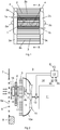
- Fig. 1 shows a front view of a cooling module.
- the cooling module comprises a condenser 1 of an AC system in a front position.
- the condenser 1 receives a gaseous refrigerant via an inlet line 1a.
- the refrigerant is cooled in the condenser 1 by a cooling air flow to a temperature at which it condenses.
- the liquefied refrigerant leaves the condenser 1 via an outlet line 1b.
- a charge air cooler 2 is arranged in a position behind the condenser 1.
- the charge air cooler 2 comprises an inlet tank 2a, a cooling portion 2b and an outlet tank 2c. Charged air is delivered to the inlet tank 2a via an inlet conduit 2a 1 .
- the charged air is cooled in the cooling portion 2b by a cooling air flow.
- the cooled charged air is received in the outlet tank 2c before it leaves the charge air cooler 2 via an outlet conduit 2c 1 .
- a radiator 3 is arranged in a position behind the charge air cooler 2.
- the radiator 3 comprises an inlet tank 3a, a cooling portion 3b and an outlet tank 3c. Coolant is received in the inlet tank 3a.
- the coolant is delivered to the cooling portion 3b where it is cooled by a cooling air flow.
- the cooled coolant is received in the outlet tube 1c before it leaves the radiator 3.
- Two additional fans 4 are indicated with dotted lines.
- the additional fans 4 are arranged behind the radiator 3.
- the additional fans 4 are operated by means of a respective electric engine 4a.
- the fans 4 and the electric engine 4a are mounted as a unit in a position close to the radiator 3.
- the fans 4 and the electrical engines 4a may be mounted by means of suitable mounting profiles attached to the inlet tank 3a and the
- Fig.2 show a cross-sectional view in the plane A-A in Fig. 1 .
- the condenser 1, the charge air cooler 2 and the radiator 3 is arranged in a flow passage 5 in a vehicle 6 which may be a heavy vehicle.
- the flow passage 5 comprises an opening 5a arranged in a front portion of the vehicle 5.
- a front wall 7 of the vehicle and a bumper 8 defines the opening 5a of the flow passage 5.
- a grille 9 is arranged in the opening 5a.
- the grille 9 is, in this case, defined by a number of vertical bars having a parallel extension across the opening 5a of the air passage 5.
- a radiator fan 10 is configured to provide a cooling air flow through the cooling module in the flow passage 5.
- the radiator fan 10 is driven by a combustion engine 11 via a clutch 12.
- a control unit 13 controls the engagement and the disengagement of the clutch 12.
- the combustion engine 11 is arranged in an engine room 14 of the vehicle 6.
- the control unit 13 receives substantially continuously information from a temperature sensor 15 about the temperature of coolant which is cooled in the radiator 3 and which cools the combustion engine 11.
- the control unit 13 starts the radiator fan 10 when the coolant has a temperature above a predetermined temperature.
- the radiator fan 10 provides an air flow in an intended flow direction through the flow passage 5.
- the air flow constitutes of ambient air which it directed into the flow passage 5, via the inlet opening 5a.
- the air flows through the condenser 1, the charge air cooler 2 and the radiator 3.
- the air flow cools the refrigerant in the condenser 1, the charge air in the charge air cooler 2 and the coolant in the radiator 3.
- the condenser 1 is arranged in the flow passage 5 in a position relatively close to the inlet opening 5a and the grille 9.
- the charge air cooler 2 is arranged at a distance behind the condenser 1.
- a first annular element 16 is arranged in the space between the condenser 1 and the charge air cooler 2.
- the first annular element 16 is attached on the condenser 1 and/or the charge air cooler 2.
- the radiator 3 is arranged at a distance behind the charge air cooler 2.
- a second annular element 17 is arranged in the space between the charge air cooler 2 and the radiator 3.
- the second annular element 17 is attached on the charge air cooler 2 and/or the radiator.
- the first annular element 16 and the second annular element 17 forms together with air flow passages through the condenser 1, air flow passages through the charge air cooler 2, air flow passages through the radiator 3 and a fan cover 4b of the additional fan 4 an air channel 18 in a restricted portion of the flow passage 5.
- Each additional fan 4 is configured to provide an air flow through such an air channel 18.
- the control unit 13 controls the activation of the electric engine 4a and the speed of the additional fan 4.
- the speed of the additional electrically driven fans may be regulated in a stepless manner.
- the additional fans 4 are reversible in its direction of rotation. Thus, it is possible to provide an air flow through the air channel 18 in the intended flow direction through the flow passage 5 and in an opposite direction to the intended flow direction through the flow passage 5.
- the use of the additional fans 4 has several applications.
- a driver wishes to take a break a warm day, it is possible to start the AC system when the combustion engine is not in operation.
- the driver can indicate start of the AC system by means of a button 19 or the like.
- the control unit 13 initiates supply of electrical energy from a battery or the like in the vehicle 6 to a compressor of the AC system and to the electrical engines 4a powering the additional electrically driven fans 4.
- the additional fans 4 start and they provide an air flow through the respective air channel 18 in the intended flow direction through the air passage 5. Ambient air is sucked into the flow passages 5, via the opening 5a, and through the air channels 18.
- the air flow through the air channels 18 provides a required cooling of the refrigerant in the condenser 1.
- the annular elements 16, 17 and the fan cover 4b of the additional fans 4, define a substantially tight air channel 18.
- Substantially the whole air flow provided by the respective additional fans 4 is directed through the condenser 1.
- additional electrically driven fans 4 with a relatively small capacity. It is usually an empty space in the flow passage 5 in a position between the radiator 5 and the radiator fan 10 which is defined by the radiator fan cover 10a.
- the additionally fans 4 and the electrical engines 4a are arranged in this space. Consequently, the additional fans 4 are arranged in a downstream position of the radiator 3 and in an upstream position of the radiator fan 10 with respect to the intended flow direction through the flow passage 5.
- the control unit 13 may receive information from a temperature sensor 20 about ambient temperature or the temperature of the charged air leaving the charge air cooler 2. In case the received temperature indicates such a risk, the control unit 13 activates the additionally fans 4 such that they provide an air flow in the flow channels 18 in an opposite direction to the intended flow direction through the flow passage 5.
- the additional fan 4 provide an air flow from the engine room 14 and through the air channels 18.
- the air flows in the air channels 18 are directed through the radiator 3, the charged air cooler 2 and the condenser 1.
- the air inside the engine room 14 has usually a considerably higher temperature than ambient air since it is in contact with the combustion engine 11. Consequently, relatively hot air flows from the engine room 14 and through the charge air cooler 2 where it melt possible ice formations.
- the additionally fans 4 instead of the radiator fan 10 for cooling of the refrigerant in the condenser 1 during certain operating conditions such as city driving. In city traffic, the ram air flow through the condenser 1 is many time too low for cooling the refrigerant. In this case, it is possible to start the additional fans 4 instead of the radiator fan 10 for cooling the refrigerant in the condenser 1. In case the additional fans 4 are dimensioned for this purpose, it is usually more energy efficient to start them than to start the considerably larger radiator fan 10.
- the cooling module may, for example, comprise a variable number of coolers.
Landscapes
- Engineering & Computer Science (AREA)
- Chemical & Material Sciences (AREA)
- Combustion & Propulsion (AREA)
- Mechanical Engineering (AREA)
- General Engineering & Computer Science (AREA)
- Transportation (AREA)
- Physics & Mathematics (AREA)
- Thermal Sciences (AREA)
- Cooling, Air Intake And Gas Exhaust, And Fuel Tank Arrangements In Propulsion Units (AREA)
Description
- The present invention relates to a vehicle according to
claim 1. - An AC system is commonly used to cool the cab space in a vehicle. AC systems comprise a cooling circuit with a circulating refrigerant. The circulating refrigerant cools the air in the cab space when it vaporizes in an evaporator and gives off heat to surrounding air when it condenses in a condenser. The condenser is usually situated at the front portion of the vehicle near to the radiator in which the coolant in the engine's cooling system is cooled. During operation, air is drawn through the condenser and the radiator by a radiator fan driven by the engine. The engine also drives a compressor which compresses and circulates the refrigerant in the AC system.
- It is often desired to use the AC system in the vehicle even at times when the engine is not running. A known practice in this respect is to run the compressor on electrical energy and use an electrically driven fan to force a cooling air flow through the condenser. However, there is usually no space for an electrically driven fan in a position close to the ordinary condenser. AC systems are known to be equipped with an additional condenser and an electrically driven fan located at a distance from the ordinary condenser for operation of the AC system when the engine is not running. The existence of two condensers increases the number of components of the AC system at the same time as it complicates the operation of the AC system.
- The amount of air which can be supplied to a supercharged combustion engine depends on the pressure of the air but also on the temperature of the air. Therefore, the charged air is cooled in a charged air cooler before it is enters the combustion engine. The charged air cooler may be arranged at a front portion of a vehicle where it is cooled by ambient air. When ambient air has a low temperature, the charged air can be cooled to a temperature below the dew point temperature of the air. In this case, liquid water is formed in the charge air cooler. When ambient air temperature is below 0°C, there is also risk that the liquid water freezes to ice in the charge air cooler. Such ice formation will cause a greater or lesser amount of obstruction of the airflow ducts within the charge air cooler, resulting in a reduced flow of air to the combustion engine and consequent operational malfunctions or stoppages.
-
DE 10 2011 006 350 A1 shows a fan arrangement for moving cool air into an air path through a cooling module. The fan arrangement comprises a fan shroud including a main fan driven by an engine and a number of electrically driven fans arranged in parallel to the main fan. The electrically driven fans provide complementary air paths at the side of a main air path provided by the main fan. Such a positioning of the electrically driven fans is space consuming since it requires a wider flow channel in order to accommodate the electrically driven fans. -
US 2010/116229 A1 shows a cooling device for a vehicle where the driving force of the cooling air flow can be selected from either an electric fan or a fan driven by the engine in accordance with preset conditions. -
EP 2875979 A1 shows a heat exchanger being adapted for air to flow through it and being adapted to be selectively employed as a refrigerant condenser or a refrigerant evaporator, and a fan being configured to be reversible and in a first operating mode delivering fresh air toward the engine compartment and in a second operating mode delivering air from the engine compartment toward the fresh air opening. -
JP 2008106727 A -
WO 2007126372 A1 shows a radiator fan arrangement for avehicle 2 which is powered by acombustion engine 2. The radiator fan arrangement comprises a first radiator fan for cooling acooling element first radiator fan 20, 26 cannot provide sufficient air flow. - The object of the present invention is to add at least one electrically driven fan to a radiator fan in a vehicle where the existence of the additional electrically driven fan does not require any extra space in the vehicle.
- The above mentioned object is achieved by the fan arrangement of the vehicle according to
claim 1. A cooling module in a vehicle may comprise a radiator and at least one other cooler defined as further cooler. During certain occasions, it is desired to provide an air flow through the further cooler when the radiator fan is not in operation. However, it is a problem to find a suitable mounting position for such an additional fan. The area in front of the further cooler is usually occupied by a grille. The area behind the further cooler is usually occupied by the radiator or another cooler. However, there is usually an empty space between the radiator and the radiator fan inside the fan shroud where it is possible to arrange an additional electrically driven fan. In this case, the additional electrically driven fan is not positioned adjacent to the further cooler but it is possible to provide an air flow through the radiator and the further cooler by the additional fan. The fan and the electrical engine may be mounted as a unit in this empty space. - According to an embodiment of the invention, the electrically driven fan is arranged in the flow passage in a position closer to the radiator than to the radiator fan. A positioning of the additional electrically driven fan adjacent to the radiator makes it easier to provide a relatively concentrated air flow through the radiator and the further cooler on the opposite side of the radiator. The additional electrically driven fan may be arranged in a part of the flow passage defined by a fan cover of the radiator fan. A radiator fan is usually provided with a fan cover in order to provide an efficient air flow through the radiator fan. Such a fan cover provides an empty space in front of the radiator fan where it is possible to arrange one or several additional electrically driven fans.
- The fan arrangement comprises at least one component configured to provide an air channel defining said restricted portion of the flow passage. It is desired to use a relatively small additional fan which does not require a large supply of electrical energy. As a consequence, the additional electrically driven fan is not able to provide an air flow through the entire flow passage and through the entire cooling module. By means of an air channel within flow passage, it is possible to provide a concentrated air flow through a relevant part of the further cooler by means of a relatively small additional fan. The air channel may be defined by an annular element arranged in a space between the further cooler and the radiator. In this case, it is possible to provide a substantially leak free air flow between the further cooler and the additional fan via the radiator. The annular element may be manufactured of a suitable plastic material. Preferably, the annular element is attachable to the further cooler and the radiator. The annular elements may be provided with projecting fastening portions which are attachable in the flow channels of the cooler/radiator.
- The cooling module comprises at least one additional further cooler. The further coolers may be a condenser of an AC system, a charged air cooler, an EGR cooler, oil cooler etc. The air channel is defined by an annular element arranged in a space between the two coolers. Also in this case, the annular element may include fastening portion for attachment to the respective cooler. In this case, it is possible to provide a substantially leak free air flow by the additional fan between the two further coolers. The air channel may be defined by a fan cover of the additional electrically driven fan. Such a fan cover may define a substantially leak free part of the air channel between the radiator and the additional electrically driven fan.
- According to the invention, the additional electrically driven fan is able to provide an air flow through the restricted portion of the flow passage in an opposite direction to the intended flow direction through the flow passage. Such an additional electrically driven fan may be reversible in its direction of rotation such that it is also able to provide an air flow in the intended flow direction of the flow passage.
- The further cooler is a charge air cooler cooling charge air delivered to the combustion engine, wherein the additional electrically driven fan is configured to provide an air flow through the restricted portion of the flow passage and the charge air cooler in the opposite direction to the intended flow direction through the flow passage during occasion when there is risk for ice formation in the charge air cooler. In this case, it is possible to direct relatively warm air from the engine room of the vehicle to the charged air cooler in order to melt possible ice formations in the charge air cooler.
- In the following a preferred embodiment of the invention is described, as an example, with reference to the attached drawings, in which:
- Fig. 1
- shows a front view of a cooling module in a vehicle comprising a fan arrangement according the invention and
- Fig. 2
- shows a cross-sectional view of the cooling module in the plane A-A in
Fig. 1 . -
Fig. 1 shows a front view of a cooling module. The cooling module comprises acondenser 1 of an AC system in a front position. Thecondenser 1 receives a gaseous refrigerant via aninlet line 1a. The refrigerant is cooled in thecondenser 1 by a cooling air flow to a temperature at which it condenses. The liquefied refrigerant leaves thecondenser 1 via anoutlet line 1b. Acharge air cooler 2 is arranged in a position behind thecondenser 1. Thecharge air cooler 2 comprises aninlet tank 2a, a coolingportion 2b and anoutlet tank 2c. Charged air is delivered to theinlet tank 2a via aninlet conduit 2a1. The charged air is cooled in the coolingportion 2b by a cooling air flow. The cooled charged air is received in theoutlet tank 2c before it leaves thecharge air cooler 2 via anoutlet conduit 2c1. Aradiator 3 is arranged in a position behind thecharge air cooler 2. Theradiator 3 comprises aninlet tank 3a, a coolingportion 3b and anoutlet tank 3c. Coolant is received in theinlet tank 3a. The coolant is delivered to the coolingportion 3b where it is cooled by a cooling air flow. The cooled coolant is received in the outlet tube 1c before it leaves theradiator 3. Twoadditional fans 4 are indicated with dotted lines. Theadditional fans 4 are arranged behind theradiator 3. Theadditional fans 4 are operated by means of a respectiveelectric engine 4a. Thefans 4 and theelectric engine 4a are mounted as a unit in a position close to theradiator 3. Thefans 4 and theelectrical engines 4a may be mounted by means of suitable mounting profiles attached to theinlet tank 3a and theoutlet tank 3c of theradiator 3. -
Fig.2 show a cross-sectional view in the plane A-A inFig. 1 . Thecondenser 1, thecharge air cooler 2 and theradiator 3 is arranged in a flow passage 5 in avehicle 6 which may be a heavy vehicle. The flow passage 5 comprises anopening 5a arranged in a front portion of the vehicle 5. Afront wall 7 of the vehicle and abumper 8 defines theopening 5a of the flow passage 5. Agrille 9 is arranged in theopening 5a. Thegrille 9 is, in this case, defined by a number of vertical bars having a parallel extension across theopening 5a of the air passage 5. Aradiator fan 10 is configured to provide a cooling air flow through the cooling module in the flow passage 5. Theradiator fan 10 is driven by acombustion engine 11 via a clutch 12. Acontrol unit 13 controls the engagement and the disengagement of the clutch 12. - The
combustion engine 11 is arranged in anengine room 14 of thevehicle 6. Thecontrol unit 13 receives substantially continuously information from atemperature sensor 15 about the temperature of coolant which is cooled in theradiator 3 and which cools thecombustion engine 11. Thecontrol unit 13 starts theradiator fan 10 when the coolant has a temperature above a predetermined temperature. During operation, theradiator fan 10 provides an air flow in an intended flow direction through the flow passage 5. The air flow constitutes of ambient air which it directed into the flow passage 5, via theinlet opening 5a. In the flow passage 5, the air flows through thecondenser 1, thecharge air cooler 2 and theradiator 3. The air flow cools the refrigerant in thecondenser 1, the charge air in thecharge air cooler 2 and the coolant in theradiator 3. - The
condenser 1 is arranged in the flow passage 5 in a position relatively close to theinlet opening 5a and thegrille 9. Thecharge air cooler 2 is arranged at a distance behind thecondenser 1. A first annular element 16 is arranged in the space between thecondenser 1 and thecharge air cooler 2. The first annular element 16 is attached on thecondenser 1 and/or thecharge air cooler 2. Theradiator 3 is arranged at a distance behind thecharge air cooler 2. A secondannular element 17 is arranged in the space between thecharge air cooler 2 and theradiator 3. The secondannular element 17 is attached on thecharge air cooler 2 and/or the radiator. The first annular element 16 and the secondannular element 17 forms together with air flow passages through thecondenser 1, air flow passages through thecharge air cooler 2, air flow passages through theradiator 3 and afan cover 4b of theadditional fan 4 anair channel 18 in a restricted portion of the flow passage 5. Eachadditional fan 4 is configured to provide an air flow through such anair channel 18. Thecontrol unit 13 controls the activation of theelectric engine 4a and the speed of theadditional fan 4. The speed of the additional electrically driven fans may be regulated in a stepless manner. Theadditional fans 4 are reversible in its direction of rotation. Thus, it is possible to provide an air flow through theair channel 18 in the intended flow direction through the flow passage 5 and in an opposite direction to the intended flow direction through the flow passage 5. - The use of the
additional fans 4 has several applications. When a driver wishes to take a break a warm day, it is possible to start the AC system when the combustion engine is not in operation. In this case, the driver can indicate start of the AC system by means of abutton 19 or the like. When this is indicated, thecontrol unit 13 initiates supply of electrical energy from a battery or the like in thevehicle 6 to a compressor of the AC system and to theelectrical engines 4a powering the additional electrically drivenfans 4. Theadditional fans 4 start and they provide an air flow through therespective air channel 18 in the intended flow direction through the air passage 5. Ambient air is sucked into the flow passages 5, via theopening 5a, and through theair channels 18. The air flow through theair channels 18 provides a required cooling of the refrigerant in thecondenser 1. Theannular elements 16, 17 and thefan cover 4b of theadditional fans 4, define a substantiallytight air channel 18. By means ofsuch air channels 18, it is possible to provide concentrated air flows through relevant parts of thecondenser 1. Substantially the whole air flow provided by the respectiveadditional fans 4 is directed through thecondenser 1. As a consequence, it is possible to use additional electrically drivenfans 4 with a relatively small capacity. It is usually an empty space in the flow passage 5 in a position between the radiator 5 and theradiator fan 10 which is defined by theradiator fan cover 10a. The additionallyfans 4 and theelectrical engines 4a are arranged in this space. Consequently, theadditional fans 4 are arranged in a downstream position of theradiator 3 and in an upstream position of theradiator fan 10 with respect to the intended flow direction through the flow passage 5. - Another application of the additionally
fans 4, it is when the combustion engine is operated and ambient air has a very low temperature. During such occasions, the radiator fan is usually not driven. Since the combustion engine is operated, charged air is directed to thecharge air cooler 2. During such occasions, the water vapor in the charge air may be liquefied and frozen in thecharge air cooler 2. If it occurs, the supply of charge air to thecombustion engine 11 will be reduced and possibly ceased. In order to avoid this risk, thecontrol unit 13 may receive information from atemperature sensor 20 about ambient temperature or the temperature of the charged air leaving thecharge air cooler 2. In case the received temperature indicates such a risk, thecontrol unit 13 activates the additionallyfans 4 such that they provide an air flow in theflow channels 18 in an opposite direction to the intended flow direction through the flow passage 5. As a consequence, theadditional fan 4 provide an air flow from theengine room 14 and through theair channels 18. The air flows in theair channels 18 are directed through theradiator 3, the chargedair cooler 2 and thecondenser 1. The air inside theengine room 14 has usually a considerably higher temperature than ambient air since it is in contact with thecombustion engine 11. Consequently, relatively hot air flows from theengine room 14 and through thecharge air cooler 2 where it melt possible ice formations. - Finally, it is possible to use the additionally
fans 4 instead of theradiator fan 10 for cooling of the refrigerant in thecondenser 1 during certain operating conditions such as city driving. In city traffic, the ram air flow through thecondenser 1 is many time too low for cooling the refrigerant. In this case, it is possible to start theadditional fans 4 instead of theradiator fan 10 for cooling the refrigerant in thecondenser 1. In case theadditional fans 4 are dimensioned for this purpose, it is usually more energy efficient to start them than to start the considerablylarger radiator fan 10. - The invention is not restricted to the described embodiment but may be varied freely within the scope of the claims. The cooling module may, for example, comprise a variable number of coolers.
Claims (6)
- A vehicle comprising a combustion engine (11), a fan arrangement and a cooling module arranged in a flow passage (5) in the vehicle, wherein the fan arrangement comprises a radiator fan (10) driven by the combustion engine (11) and configured to provide an air flow in an intended direction through the flow passage (5) and the cooling module, wherein the cooling module comprises a radiator (3) of a cooling system cooling a combustion engine (11) and at least one further cooler (1, 2) arranged in an upstream position of the radiator (3) with respect to said intended flow direction through the flow passage (5), wherein the fan arrangement comprises at least one additional electrically driven fan (4), wherein the at least one additional electrically driven fan (4) is arranged in the flow passage (5) in a position downstream of the radiator (3) and upstream of the radiator fan (10) with respect to said intended flow direction through the flow passage (5) and wherein the at least one additional electrically driven fan (4) is configured to provide an air flow through a restricted portion (18) of the flow passage (5) and the cooling module during certain occasions when the radiator fan (10) is not in operation, wherein the at least one additional electrically driven fan (4) is able to provide an air flow through the restricted portion (18) in an opposite direction to the intended flow direction through the flow passage (5) and wherein the further cooler is a charge air cooler (2) cooling charge air delivered to the combustion engine (11), wherein the electrically driven fan (4) is configured to provide an air flow through the restricted portion (18) of the flow passage (5) and the charge air cooler (2) in the opposite direction to the intended flow direction through the flow passage (5) during occasion when there is risk for ice formation in the charge air cooler (2), wherein the vehicle further comprises a control unit (13) configured to receive information from a temperature sensor (20) about ambient temperature or the temperature of the charged air leaving the charge air cooler (2) and activate the at least one additional electrically driven fan (4) such that it provides the air flow through the restricted portion (18) in the opposite direction to the intended flow direction through the flow passage (5) in case the received temperature indicates a risk for ice formation in the charge air cooler (2), wherein the fan arrangement comprises at least one component configured to provide an air channel (18) defining said restricted portion of the flow passage (5) and the cooling module comprises at least one additional further cooler (1, 2), and wherein said air channel (18) within the flow passage (5) is defined by an annular element (16) arranged in a space between said two coolers (1, 2).
- A vehicle according to claim 1, characterized in that the at least one additional electrically driven fan (4) is arranged in the flow passage (5) in a position closer to the radiator (3) than to the radiator fan (10).
- A vehicle according to claim 1 or 2, characterized in that the at least one additional electrically driven fan (4) is arranged in a part of the flow passage (5) defined by a fan cover (10a) of the radiator fan (10).
- A vehicle according to any one of the preceding claims, characterized in that said air channel (18) within the flow passage (5) is further defined by an annular element (17) arranged in a space between the further cooler (2) and the radiator (3).
- A vehicle according to any one of the preceding claims, characterized in that said air channel (18) within the flow passage (5) is further defined by a fan cover (4b) of the at least one additional electrically driven fan (4).
- A vehicle according to any one of the preceding claims, characterized in that the at least one additional electrically driven fan (4) is reversible in its direction of rotation.
Applications Claiming Priority (2)
| Application Number | Priority Date | Filing Date | Title |
|---|---|---|---|
| SE1650042A SE542203C2 (en) | 2016-01-15 | 2016-01-15 | A vehicle with a fan arrangement |
| PCT/SE2016/051254 WO2017123131A1 (en) | 2016-01-15 | 2016-12-13 | A fan arrangement in a vehicle |
Publications (3)
| Publication Number | Publication Date |
|---|---|
| EP3402971A1 EP3402971A1 (en) | 2018-11-21 |
| EP3402971A4 EP3402971A4 (en) | 2019-07-31 |
| EP3402971B1 true EP3402971B1 (en) | 2021-03-24 |
Family
ID=59311420
Family Applications (1)
| Application Number | Title | Priority Date | Filing Date |
|---|---|---|---|
| EP16885286.1A Active EP3402971B1 (en) | 2016-01-15 | 2016-12-13 | A fan arrangement in a vehicle |
Country Status (5)
| Country | Link |
|---|---|
| US (1) | US20200300153A1 (en) |
| EP (1) | EP3402971B1 (en) |
| CN (1) | CN108474292A (en) |
| SE (1) | SE542203C2 (en) |
| WO (1) | WO2017123131A1 (en) |
Families Citing this family (7)
| Publication number | Priority date | Publication date | Assignee | Title |
|---|---|---|---|---|
| US10661650B2 (en) | 2016-07-22 | 2020-05-26 | Nimer Ibrahim Shiheiber | Radiator system |
| JP7010724B2 (en) | 2018-02-19 | 2022-01-26 | トヨタ自動車株式会社 | Vehicle cooling system |
| JP7067420B2 (en) * | 2018-10-31 | 2022-05-16 | トヨタ自動車株式会社 | Cooling system |
| SE543871C2 (en) * | 2018-12-14 | 2021-08-17 | Scania Cv Ab | Radiator assembly, Powertrain, and Vehicle |
| KR20220104441A (en) * | 2021-01-18 | 2022-07-26 | 현대자동차주식회사 | Integrated module for radiator and intercooler and vehicle including the same |
| US11821392B2 (en) * | 2021-11-17 | 2023-11-21 | Ford Global Technologies, Llc | Method and system for radiator fan operation for charge air cooler ice elimination |
| DE102023105066A1 (en) * | 2023-03-01 | 2024-09-05 | Deere & Company | Method for operating a vehicle cooling system |
Family Cites Families (13)
| Publication number | Priority date | Publication date | Assignee | Title |
|---|---|---|---|---|
| JPS5910727A (en) * | 1982-07-09 | 1984-01-20 | Nissan Motor Co Ltd | Cooling device for engine |
| DE3702267A1 (en) * | 1987-01-27 | 1988-08-04 | Bayerische Motoren Werke Ag | Arrangement of at least two air-liquid heat exchangers on motor vehicles |
| DE3820163A1 (en) * | 1988-06-14 | 1989-12-21 | Kloeckner Humboldt Deutz Ag | Air-cooled internal combustion engine |
| DE4122512A1 (en) * | 1991-05-28 | 1992-12-03 | Kloeckner Humboldt Deutz Ag | COMPACT HEAT EXCHANGER FAN UNIT |
| DE19910651A1 (en) * | 1998-03-13 | 1999-09-16 | Denso Corp | Engine cooling device for vehicle |
| US7669557B2 (en) * | 2006-02-08 | 2010-03-02 | Toyota Jidosha Kabushiki Kaisha | Cooling device for vehicle |
| CN101432507B (en) | 2006-04-28 | 2012-05-02 | 斯堪尼亚有限公司 | Cooling fan arrangement at a vehicle |
| SE530032C2 (en) * | 2006-06-30 | 2008-02-12 | Scania Cv Abp | Radiator for a motor vehicle |
| JP2008106727A (en) | 2006-10-27 | 2008-05-08 | Honda Motor Co Ltd | Air intake device at the front of the vehicle |
| SE535564C2 (en) * | 2010-12-22 | 2012-09-25 | Scania Cv Ab | Cooling system in a vehicle |
| DE102011006350A1 (en) * | 2011-03-29 | 2012-10-04 | Behr Gmbh & Co. Kg | Ventilation device for cooling system of e.g. passenger car, has two fans for moving cool air into two different respective air paths through cooling module and arranged in through-holes of shroud, where electromotor drives one of fans |
| DE102013112825A1 (en) | 2013-11-20 | 2015-05-21 | Valeo Klimasysteme Gmbh | Front module of a vehicle |
| CN103644024B (en) * | 2013-11-28 | 2016-05-04 | 长城汽车股份有限公司 | A kind of car engine air admittance humidity control system |
-
2016
- 2016-01-15 SE SE1650042A patent/SE542203C2/en unknown
- 2016-12-13 WO PCT/SE2016/051254 patent/WO2017123131A1/en not_active Ceased
- 2016-12-13 CN CN201680077440.4A patent/CN108474292A/en active Pending
- 2016-12-13 US US15/779,292 patent/US20200300153A1/en not_active Abandoned
- 2016-12-13 EP EP16885286.1A patent/EP3402971B1/en active Active
Non-Patent Citations (1)
| Title |
|---|
| None * |
Also Published As
| Publication number | Publication date |
|---|---|
| SE1650042A1 (en) | 2017-07-16 |
| SE542203C2 (en) | 2020-03-10 |
| WO2017123131A1 (en) | 2017-07-20 |
| EP3402971A1 (en) | 2018-11-21 |
| CN108474292A (en) | 2018-08-31 |
| EP3402971A4 (en) | 2019-07-31 |
| US20200300153A1 (en) | 2020-09-24 |
Similar Documents
| Publication | Publication Date | Title |
|---|---|---|
| US20200300153A1 (en) | A fan arrangement in a vehicle | |
| EP3621839B1 (en) | A cooling arrangement for cooling of an electric machine and at least one further component of an electric power unit and a vehicle comprising such a cooling arrangement | |
| US7631512B2 (en) | Vehicle cooling system | |
| US5901786A (en) | Axial fan sandwich cooling module incorporating airflow by-pass features | |
| CN101445031B (en) | HVAC thermal storage for hybrid vehicle | |
| EP3311085B1 (en) | Transport refrigeration unit and method of operating the same | |
| EP3469199B1 (en) | Cooling system for cooling an electric power unit | |
| EP2090852A2 (en) | Air conditioning system | |
| EP3058292B1 (en) | Air intake for refrigerated container assembly | |
| JPH08197937A (en) | Air conditioner for vehicle | |
| US5860595A (en) | Motor vehicle heat exhanger | |
| CN104648078A (en) | Front-End Module Of A Vehicle | |
| US9499025B2 (en) | Air-conditioning loop functioning as a pulse electro-thermal deicing heat pump | |
| KR102576259B1 (en) | Air-conditioning system for electric vehicles | |
| SE541754C2 (en) | A cooling system for an electric power unit for a vehicle | |
| KR102651941B1 (en) | Air-conditioning system for electric vehicles | |
| EP1605146B1 (en) | Coolant motor fan drive | |
| WO2017200463A1 (en) | A cooling system for a combustion engine and a further object | |
| WO2011102783A1 (en) | Arrangement for de-icing of a charge air cooler | |
| US10365027B2 (en) | Simplified and energy efficient multi temperature unit | |
| JP7352834B2 (en) | cooling system | |
| EP1971499B1 (en) | Air conditioning system for a motor vehicle | |
| US20070271943A1 (en) | Air-Conditioning System Provided With a Heat Pump | |
| CN120096275A (en) | Vehicle thermal management system | |
| JPH04212617A (en) | Vehicle cooling system |
Legal Events
| Date | Code | Title | Description |
|---|---|---|---|
| STAA | Information on the status of an ep patent application or granted ep patent |
Free format text: STATUS: THE INTERNATIONAL PUBLICATION HAS BEEN MADE |
|
| PUAI | Public reference made under article 153(3) epc to a published international application that has entered the european phase |
Free format text: ORIGINAL CODE: 0009012 |
|
| STAA | Information on the status of an ep patent application or granted ep patent |
Free format text: STATUS: REQUEST FOR EXAMINATION WAS MADE |
|
| 17P | Request for examination filed |
Effective date: 20180816 |
|
| AK | Designated contracting states |
Kind code of ref document: A1 Designated state(s): AL AT BE BG CH CY CZ DE DK EE ES FI FR GB GR HR HU IE IS IT LI LT LU LV MC MK MT NL NO PL PT RO RS SE SI SK SM TR |
|
| AX | Request for extension of the european patent |
Extension state: BA ME |
|
| DAV | Request for validation of the european patent (deleted) | ||
| DAX | Request for extension of the european patent (deleted) | ||
| A4 | Supplementary search report drawn up and despatched |
Effective date: 20190702 |
|
| RIC1 | Information provided on ipc code assigned before grant |
Ipc: F01P 5/04 20060101ALI20190626BHEP Ipc: F01P 5/02 20060101ALI20190626BHEP Ipc: F01P 3/18 20060101ALI20190626BHEP Ipc: F01P 11/10 20060101ALI20190626BHEP Ipc: B60K 11/04 20060101ALI20190626BHEP Ipc: F02B 29/04 20060101AFI20190626BHEP |
|
| STAA | Information on the status of an ep patent application or granted ep patent |
Free format text: STATUS: EXAMINATION IS IN PROGRESS |
|
| 17Q | First examination report despatched |
Effective date: 20200428 |
|
| GRAP | Despatch of communication of intention to grant a patent |
Free format text: ORIGINAL CODE: EPIDOSNIGR1 |
|
| RIC1 | Information provided on ipc code assigned before grant |
Ipc: F01P 5/02 20060101ALI20201008BHEP Ipc: F02B 29/04 20060101AFI20201008BHEP Ipc: F01P 11/10 20060101ALI20201008BHEP Ipc: B60K 1/00 20060101ALI20201008BHEP Ipc: F01P 5/04 20060101ALI20201008BHEP Ipc: F01P 3/18 20060101ALI20201008BHEP Ipc: B60K 11/04 20060101ALI20201008BHEP |
|
| STAA | Information on the status of an ep patent application or granted ep patent |
Free format text: STATUS: GRANT OF PATENT IS INTENDED |
|
| INTG | Intention to grant announced |
Effective date: 20201112 |
|
| GRAS | Grant fee paid |
Free format text: ORIGINAL CODE: EPIDOSNIGR3 |
|
| GRAA | (expected) grant |
Free format text: ORIGINAL CODE: 0009210 |
|
| STAA | Information on the status of an ep patent application or granted ep patent |
Free format text: STATUS: THE PATENT HAS BEEN GRANTED |
|
| AK | Designated contracting states |
Kind code of ref document: B1 Designated state(s): AL AT BE BG CH CY CZ DE DK EE ES FI FR GB GR HR HU IE IS IT LI LT LU LV MC MK MT NL NO PL PT RO RS SE SI SK SM TR |
|
| REG | Reference to a national code |
Ref country code: GB Ref legal event code: FG4D |
|
| REG | Reference to a national code |
Ref country code: CH Ref legal event code: EP |
|
| REG | Reference to a national code |
Ref country code: DE Ref legal event code: R096 Ref document number: 602016055032 Country of ref document: DE |
|
| REG | Reference to a national code |
Ref country code: IE Ref legal event code: FG4D |
|
| REG | Reference to a national code |
Ref country code: AT Ref legal event code: REF Ref document number: 1374715 Country of ref document: AT Kind code of ref document: T Effective date: 20210415 |
|
| RAP4 | Party data changed (patent owner data changed or rights of a patent transferred) |
Owner name: SCANIA CV AB |
|
| REG | Reference to a national code |
Ref country code: LT Ref legal event code: MG9D |
|
| PG25 | Lapsed in a contracting state [announced via postgrant information from national office to epo] |
Ref country code: NO Free format text: LAPSE BECAUSE OF FAILURE TO SUBMIT A TRANSLATION OF THE DESCRIPTION OR TO PAY THE FEE WITHIN THE PRESCRIBED TIME-LIMIT Effective date: 20210624 Ref country code: GR Free format text: LAPSE BECAUSE OF FAILURE TO SUBMIT A TRANSLATION OF THE DESCRIPTION OR TO PAY THE FEE WITHIN THE PRESCRIBED TIME-LIMIT Effective date: 20210625 Ref country code: FI Free format text: LAPSE BECAUSE OF FAILURE TO SUBMIT A TRANSLATION OF THE DESCRIPTION OR TO PAY THE FEE WITHIN THE PRESCRIBED TIME-LIMIT Effective date: 20210324 Ref country code: HR Free format text: LAPSE BECAUSE OF FAILURE TO SUBMIT A TRANSLATION OF THE DESCRIPTION OR TO PAY THE FEE WITHIN THE PRESCRIBED TIME-LIMIT Effective date: 20210324 Ref country code: BG Free format text: LAPSE BECAUSE OF FAILURE TO SUBMIT A TRANSLATION OF THE DESCRIPTION OR TO PAY THE FEE WITHIN THE PRESCRIBED TIME-LIMIT Effective date: 20210624 |
|
| PG25 | Lapsed in a contracting state [announced via postgrant information from national office to epo] |
Ref country code: SE Free format text: LAPSE BECAUSE OF FAILURE TO SUBMIT A TRANSLATION OF THE DESCRIPTION OR TO PAY THE FEE WITHIN THE PRESCRIBED TIME-LIMIT Effective date: 20210324 Ref country code: LV Free format text: LAPSE BECAUSE OF FAILURE TO SUBMIT A TRANSLATION OF THE DESCRIPTION OR TO PAY THE FEE WITHIN THE PRESCRIBED TIME-LIMIT Effective date: 20210324 Ref country code: RS Free format text: LAPSE BECAUSE OF FAILURE TO SUBMIT A TRANSLATION OF THE DESCRIPTION OR TO PAY THE FEE WITHIN THE PRESCRIBED TIME-LIMIT Effective date: 20210324 |
|
| REG | Reference to a national code |
Ref country code: NL Ref legal event code: MP Effective date: 20210324 |
|
| REG | Reference to a national code |
Ref country code: AT Ref legal event code: MK05 Ref document number: 1374715 Country of ref document: AT Kind code of ref document: T Effective date: 20210324 |
|
| PG25 | Lapsed in a contracting state [announced via postgrant information from national office to epo] |
Ref country code: NL Free format text: LAPSE BECAUSE OF FAILURE TO SUBMIT A TRANSLATION OF THE DESCRIPTION OR TO PAY THE FEE WITHIN THE PRESCRIBED TIME-LIMIT Effective date: 20210324 |
|
| PG25 | Lapsed in a contracting state [announced via postgrant information from national office to epo] |
Ref country code: SM Free format text: LAPSE BECAUSE OF FAILURE TO SUBMIT A TRANSLATION OF THE DESCRIPTION OR TO PAY THE FEE WITHIN THE PRESCRIBED TIME-LIMIT Effective date: 20210324 Ref country code: AT Free format text: LAPSE BECAUSE OF FAILURE TO SUBMIT A TRANSLATION OF THE DESCRIPTION OR TO PAY THE FEE WITHIN THE PRESCRIBED TIME-LIMIT Effective date: 20210324 Ref country code: CZ Free format text: LAPSE BECAUSE OF FAILURE TO SUBMIT A TRANSLATION OF THE DESCRIPTION OR TO PAY THE FEE WITHIN THE PRESCRIBED TIME-LIMIT Effective date: 20210324 Ref country code: EE Free format text: LAPSE BECAUSE OF FAILURE TO SUBMIT A TRANSLATION OF THE DESCRIPTION OR TO PAY THE FEE WITHIN THE PRESCRIBED TIME-LIMIT Effective date: 20210324 Ref country code: LT Free format text: LAPSE BECAUSE OF FAILURE TO SUBMIT A TRANSLATION OF THE DESCRIPTION OR TO PAY THE FEE WITHIN THE PRESCRIBED TIME-LIMIT Effective date: 20210324 |
|
| PG25 | Lapsed in a contracting state [announced via postgrant information from national office to epo] |
Ref country code: SK Free format text: LAPSE BECAUSE OF FAILURE TO SUBMIT A TRANSLATION OF THE DESCRIPTION OR TO PAY THE FEE WITHIN THE PRESCRIBED TIME-LIMIT Effective date: 20210324 Ref country code: RO Free format text: LAPSE BECAUSE OF FAILURE TO SUBMIT A TRANSLATION OF THE DESCRIPTION OR TO PAY THE FEE WITHIN THE PRESCRIBED TIME-LIMIT Effective date: 20210324 Ref country code: PL Free format text: LAPSE BECAUSE OF FAILURE TO SUBMIT A TRANSLATION OF THE DESCRIPTION OR TO PAY THE FEE WITHIN THE PRESCRIBED TIME-LIMIT Effective date: 20210324 Ref country code: PT Free format text: LAPSE BECAUSE OF FAILURE TO SUBMIT A TRANSLATION OF THE DESCRIPTION OR TO PAY THE FEE WITHIN THE PRESCRIBED TIME-LIMIT Effective date: 20210726 Ref country code: IS Free format text: LAPSE BECAUSE OF FAILURE TO SUBMIT A TRANSLATION OF THE DESCRIPTION OR TO PAY THE FEE WITHIN THE PRESCRIBED TIME-LIMIT Effective date: 20210724 |
|
| REG | Reference to a national code |
Ref country code: DE Ref legal event code: R097 Ref document number: 602016055032 Country of ref document: DE |
|
| PG25 | Lapsed in a contracting state [announced via postgrant information from national office to epo] |
Ref country code: ES Free format text: LAPSE BECAUSE OF FAILURE TO SUBMIT A TRANSLATION OF THE DESCRIPTION OR TO PAY THE FEE WITHIN THE PRESCRIBED TIME-LIMIT Effective date: 20210324 Ref country code: AL Free format text: LAPSE BECAUSE OF FAILURE TO SUBMIT A TRANSLATION OF THE DESCRIPTION OR TO PAY THE FEE WITHIN THE PRESCRIBED TIME-LIMIT Effective date: 20210324 Ref country code: DK Free format text: LAPSE BECAUSE OF FAILURE TO SUBMIT A TRANSLATION OF THE DESCRIPTION OR TO PAY THE FEE WITHIN THE PRESCRIBED TIME-LIMIT Effective date: 20210324 |
|
| PLBE | No opposition filed within time limit |
Free format text: ORIGINAL CODE: 0009261 |
|
| STAA | Information on the status of an ep patent application or granted ep patent |
Free format text: STATUS: NO OPPOSITION FILED WITHIN TIME LIMIT |
|
| PG25 | Lapsed in a contracting state [announced via postgrant information from national office to epo] |
Ref country code: SI Free format text: LAPSE BECAUSE OF FAILURE TO SUBMIT A TRANSLATION OF THE DESCRIPTION OR TO PAY THE FEE WITHIN THE PRESCRIBED TIME-LIMIT Effective date: 20210324 |
|
| 26N | No opposition filed |
Effective date: 20220104 |
|
| PG25 | Lapsed in a contracting state [announced via postgrant information from national office to epo] |
Ref country code: IS Free format text: LAPSE BECAUSE OF FAILURE TO SUBMIT A TRANSLATION OF THE DESCRIPTION OR TO PAY THE FEE WITHIN THE PRESCRIBED TIME-LIMIT Effective date: 20210724 |
|
| PG25 | Lapsed in a contracting state [announced via postgrant information from national office to epo] |
Ref country code: MC Free format text: LAPSE BECAUSE OF FAILURE TO SUBMIT A TRANSLATION OF THE DESCRIPTION OR TO PAY THE FEE WITHIN THE PRESCRIBED TIME-LIMIT Effective date: 20210324 |
|
| REG | Reference to a national code |
Ref country code: CH Ref legal event code: PL |
|
| GBPC | Gb: european patent ceased through non-payment of renewal fee |
Effective date: 20211213 |
|
| REG | Reference to a national code |
Ref country code: BE Ref legal event code: MM Effective date: 20211231 |
|
| PG25 | Lapsed in a contracting state [announced via postgrant information from national office to epo] |
Ref country code: LU Free format text: LAPSE BECAUSE OF NON-PAYMENT OF DUE FEES Effective date: 20211213 Ref country code: IE Free format text: LAPSE BECAUSE OF NON-PAYMENT OF DUE FEES Effective date: 20211213 Ref country code: GB Free format text: LAPSE BECAUSE OF NON-PAYMENT OF DUE FEES Effective date: 20211213 |
|
| PG25 | Lapsed in a contracting state [announced via postgrant information from national office to epo] |
Ref country code: FR Free format text: LAPSE BECAUSE OF NON-PAYMENT OF DUE FEES Effective date: 20211231 Ref country code: BE Free format text: LAPSE BECAUSE OF NON-PAYMENT OF DUE FEES Effective date: 20211231 |
|
| PG25 | Lapsed in a contracting state [announced via postgrant information from national office to epo] |
Ref country code: LI Free format text: LAPSE BECAUSE OF NON-PAYMENT OF DUE FEES Effective date: 20211231 Ref country code: CH Free format text: LAPSE BECAUSE OF NON-PAYMENT OF DUE FEES Effective date: 20211231 |
|
| PG25 | Lapsed in a contracting state [announced via postgrant information from national office to epo] |
Ref country code: IT Free format text: LAPSE BECAUSE OF FAILURE TO SUBMIT A TRANSLATION OF THE DESCRIPTION OR TO PAY THE FEE WITHIN THE PRESCRIBED TIME-LIMIT Effective date: 20210324 |
|
| P01 | Opt-out of the competence of the unified patent court (upc) registered |
Effective date: 20230516 |
|
| PG25 | Lapsed in a contracting state [announced via postgrant information from national office to epo] |
Ref country code: CY Free format text: LAPSE BECAUSE OF FAILURE TO SUBMIT A TRANSLATION OF THE DESCRIPTION OR TO PAY THE FEE WITHIN THE PRESCRIBED TIME-LIMIT Effective date: 20210324 |
|
| PG25 | Lapsed in a contracting state [announced via postgrant information from national office to epo] |
Ref country code: HU Free format text: LAPSE BECAUSE OF FAILURE TO SUBMIT A TRANSLATION OF THE DESCRIPTION OR TO PAY THE FEE WITHIN THE PRESCRIBED TIME-LIMIT; INVALID AB INITIO Effective date: 20161213 |
|
| PG25 | Lapsed in a contracting state [announced via postgrant information from national office to epo] |
Ref country code: MK Free format text: LAPSE BECAUSE OF FAILURE TO SUBMIT A TRANSLATION OF THE DESCRIPTION OR TO PAY THE FEE WITHIN THE PRESCRIBED TIME-LIMIT Effective date: 20210324 |
|
| PG25 | Lapsed in a contracting state [announced via postgrant information from national office to epo] |
Ref country code: TR Free format text: LAPSE BECAUSE OF FAILURE TO SUBMIT A TRANSLATION OF THE DESCRIPTION OR TO PAY THE FEE WITHIN THE PRESCRIBED TIME-LIMIT Effective date: 20210324 |
|
| PG25 | Lapsed in a contracting state [announced via postgrant information from national office to epo] |
Ref country code: MT Free format text: LAPSE BECAUSE OF FAILURE TO SUBMIT A TRANSLATION OF THE DESCRIPTION OR TO PAY THE FEE WITHIN THE PRESCRIBED TIME-LIMIT Effective date: 20210324 |
|
| PGFP | Annual fee paid to national office [announced via postgrant information from national office to epo] |
Ref country code: DE Payment date: 20251028 Year of fee payment: 10 |