EP3402209A1 - System for connecting cables easily to a connector of any electronic equipment - Google Patents
System for connecting cables easily to a connector of any electronic equipment Download PDFInfo
- Publication number
- EP3402209A1 EP3402209A1 EP17170092.5A EP17170092A EP3402209A1 EP 3402209 A1 EP3402209 A1 EP 3402209A1 EP 17170092 A EP17170092 A EP 17170092A EP 3402209 A1 EP3402209 A1 EP 3402209A1
- Authority
- EP
- European Patent Office
- Prior art keywords
- connector
- connectors
- electronic equipment
- cover
- cabinet
- Prior art date
- Legal status (The legal status is an assumption and is not a legal conclusion. Google has not performed a legal analysis and makes no representation as to the accuracy of the status listed.)
- Granted
Links
Images


Classifications
-
- H—ELECTRICITY
- H04—ELECTRIC COMMUNICATION TECHNIQUE
- H04N—PICTORIAL COMMUNICATION, e.g. TELEVISION
- H04N21/00—Selective content distribution, e.g. interactive television or video on demand [VOD]
- H04N21/40—Client devices specifically adapted for the reception of or interaction with content, e.g. set-top-box [STB]; Operations thereof
- H04N21/41—Structure of client; Structure of client peripherals
- H04N21/4104—Peripherals receiving signals from specially adapted client devices
- H04N21/4112—Peripherals receiving signals from specially adapted client devices having fewer capabilities than the client, e.g. thin client having less processing power or no tuning capabilities
Definitions
- This invention refers to a system for connecting cables easily to connectors of any electronic equipment by extracting out a connector according to claim 1, a system for connecting cables easily to connectors of any electronic equipment by opening a cover of a connector according to claim 5.
- the document describes about TV signal switching box and controlling method thereof.
- the TV set signal switching box is connected between a TV set and signal sources to enable the signal sources to interact media signals with the TV set.
- the signal change in a TV set box and related control method are explained in detail.
- multiple signal sources can be concurrently connected to a multiple input / output ports. It is possible to switch between these signal sources.
- this system does not help the user to connect the cable to the appropriate connector based on input source.
- the input source can be IP, DVD and DVB set up box. Then the user may connect to the wrong socket and not able to watch/listen the appropriate signal.
- EP2439942B1 does not assist the end user or user to allow them for connecting the cable to the connector easiliy based on the input source selected by the user.
- the system preferably comprises of, a plurality of connectors, a plurality of motors, a motor control unit, and a system software.
- the plurality of connectors for the input sources are provided in a cabinet of the electronic equipment for connecting the cables. Further, the input source is selected from a menu of the electronic equipment.
- the plurality of motors is provided in the cabinet for extracting out the connectors from the cabinet for connecting the cable.
- the motor control unit is provided for controlling the plurality of motors thereby extracting the plurality of connector.
- the system software is configured for obtaining and processing signals from the menu and activating a system controller for controlling the motor control unit thereby extracting the corresponding connector of the input source selected.
- connection process may not consume much time for identifying and connecting the connectors based on the input source selected by the end user.
- the connector is extracted out from the cabinet based on the input source selected by the end user from the menu.
- Each connector of the plurality of connectors is controlled by a single motor of plurality of motors.
- the extracted connector is pulled back inside the cabinet after a predetermined duration. Further, the predetermined duration is adjusted by the end user.
- a system for connecting cables to a connector of an electronic equipment preferably comprises of a plurality of connectors, a system software, a plurality of covers, a plurality of motors, and a motor control unit.
- the plurality of connectors for the input sources provided in a cabinet of the electronic equipment for connecting the cables. Further, the input source is selected from a menu of the electronic equipment.
- the plurality of covers provided for keeping the plurality of connectors in open or closed state.
- the plurality of motors is provided in the cabinet for opening the cover of the corresponding connectors for connecting the cable.
- the motor control unit is provided for controlling the plurality of motors thereby opening the cover of the corresponding connector.
- the system software can be configured for obtaining and processing signals from the menu and activating a system controller for controlling the motor control unit thereby opening the cover of the corresponding connector of the input source selected.
- a single cover is provided for each connector.
- Each cover of the plurality of connectors is controlled by a single motor of the plurality of motors.
- the opened connector cover closes after a predetermined duration; and wherein the predetermined duration adjusted by the end user.
- Fig. 1 illustrates a block diagram 100 of a system for connecting cables 12 to connectors (1,2 & 3) of an electronic equipment by extracting out a connector, according to a preferred embodiment of the present invention.
- the system comprises of a plurality of connectors (1,2 & 3), a system controller 8, a motor control unit 7, and a plurality of motors (4, 5 & 6).
- the plurality of connectors (1,2 & 3) includes but not limited to connector 1, connector 2, connector 3 for the input sources provided in a cabinet of the electronic equipment for connecting the cables 12. Further, the input source is selected from a menu of the electronic equipment.
- the plurality of motors (4, 5 & 6) includes but not limited to motor 1, motor 2, motor 3 and that are provided in the cabinet for extracting out 13 the corresponding connector (1, 2 & 3) from the cabinet for connecting the cable 12.
- the motor control unit 7 is provided for controlling the plurality of motor (4, 5 & 6) thereby extracting the plurality of connectors (1,2 & 3). Further, each connector of the plurality of connectors (1,2 & 3) is controlled by a single motor (4, 5 & 6) of plurality of motors (4, 5 & 6). The number of electrical motors can be changed using different mechanical gear systems. Further, the connectors (1,2 & 3) are configured for a specific input source and extracted out from a cabinet in which all the connectors (1, 2 & 3) are inserted.
- the connectors (1,2 & 3) are extracted out from the cabinet based on the input source selected by the end user from the menu.
- the extracted connector (1,2 & 3) is pulled back inside the cabinet after a predetermined duration.
- the predetermined duration can be adjusted by the end user.
- a system software 14 can be configured for obtaining and processing signals from the menu and activating the system controller 8 for controlling the motor control unit 7 thereby extracting the corresponding connector (1,2 & 3) of the input source selected.
- the system software 14 is incorporated in the system controller 8 for generating control signals to activate the connector and its corresponding motor (4, 5 & 6) that need to be activated.
- Fig. 2 illustrates a block diagram 200 of a system for connecting cables 12 to connectors of an electronic equipment by opening a cover of the connector, according to a further preferred embodiment of the present invention.
- the system preferably comprises of a plurality of connectors (1,2 & 3), a system controller 8, a motor control unit 7, a plurality of cover (15, 16 &17) and a plurality of motors (9, 10 &11).
- the plurality of connectors (1,2 & 3) includes but not limited to connector 1, connector 2, connector 3 and that are provided for connecting the cables 12.
- the plurality of covers (15, 16 &17) are provided for keeping the plurality of connectors (1,2 & 3) in open or closed state.
- the plurality of motors (9, 10 &11) are provided for opening or closing the plurality of covers (15, 16 &17) for connecting the cable.
- the system software 14 can be configured for obtaining and processing signals from the menu and activating the system controller 8 for controlling the motor control unit 7 thereby opening the cover (15, 16 &17) of the corresponding connector (1,2 & 3) of the input source selected.
- the connectors (1,2 & 3) can be configured for a specific input source.
- the cover (15, 16 &17) get opened or closed based on the input source selected by the end user by means of plurality of motors (9, 10&11).
- the motor control unit 7 is provided for controlling the plurality of motors (9, 10 & 11) thereby opening the cover (15, 16 &17) of the corresponding connector (1, 2 & 3).
- the single cover is provided for each connector (1,2 & 3), and each cover (15,16 & 17) of the plurality of connectors (1,2 & 3) is controlled by a single motor.
- the covers can close the connectors (1,2 & 3) provided inside the cabinet of the electronic equipment after a predetermined duration, in case no cable is connected to the connector (1,2 & 3) or socket.
- the predetermined duration can be adjusted by the end user.
- the system controller 8 is provided for controlling the motor control unit 7 to activate respective motor (9, 10 &11) of the corresponding connector.
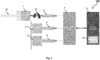
- Fig. 3 illustrates working of a system 300 for connecting cables 12 to connectors of an electronic equipment by extracting out a connector, according to a preferred embodiment.
- the method for connecting cables 12 to connectors (1,2 & 3) preferably comprises the steps of allowing a user to select an input source from a menu of the electronic equipment, based on the input source, sending a signal from a system controller 8 to activate a motor control unit 7, controllling corresponding motor (4, 5 & 6) by the motrol control unit 7 for extracting out 13 the respective connector (1,2 & 3) from a cabinet in which all connectors (1,2 & 3) are inserted, extracting out 13 the respective connector (1, 2 & 3) from the cabinet for allowing the end user to connect the cable.
- the method further includes pulling back the connector (1,2 & 3) inside the cabinet after a predetermined duration. Once the cable is connected, the connector (1,2 & 3) can return back to its original position.
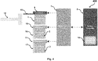
- Fig. 4 illustrates working of a system 400 for connecting cables 12 to connectors of electronic equipment by opening a cover of the connector, according to a further preferred embodiment.
- the method for connecting cables 12 to connectors (1,2 & 3) omprising the steps of allowing a user to select an input source from a menu of the electronic equipment, sending a signal from a system controller 8 to activate a motor control unit (7), controlling corresponding motor (4, 5 & 6) by the motor control unit (7) for opening a respective cover (15, 16 &17) of the respective connector (1,2 & 3) present in the cabinet in which all connectors (1,2 & 3) are inserted, opening the respective cover (15, 16 &17) of the connector (1, 2 & 3) present in the cabinet for allowing the end user to connect the cable 12.
- the method further includes closing the cover of the connector (1,2 & 3) provided in the cabinet after a predetermined duration. Once the cable is connected, the corresponding cover of the connector (1,2 & 3) can
- the present invention refers to a system a system for connecting cables 12 to a connector (1,2 & 3) of the electronic equipment by extracting out a connecter or by opening a cover of the connector solves the object mentioned. That is the system allows the user to connect cable to the appropriate connector (1,2 & 3) easily compared to the known systems and methods.
- the present invention refers to a system for connecting cables 12 to connectors of an electronic equipment either by extracting out a connector or by opening a cover of a connector based on an input source selected by an end user.
- the system comprises of plurality of connectors 1,2 & 3 that can be activated by a plurality of motors 4, 5 & 6 to extract out 13 the specific connector 1,2 & 3 from a cabinet in which plurality of connectors 1,2 & 3 are inserted.
- the system comprises of plurality of connectors 1, 2 & 3 and pllurality of covers 15, 16 &17.
- the specific covers 15, 16 &17 of the specific connector 1,2 & 3 can be opened by the plurality of motors 4, 5 & 6.
- the opening of cover of the specific connector 1, 2 & 3 or extraction of the specific connector 1, 2 & 3 out from its position is performed based on the input source selected by the end user.
Landscapes
- Engineering & Computer Science (AREA)
- Multimedia (AREA)
- Signal Processing (AREA)
- Casings For Electric Apparatus (AREA)
- Details Of Connecting Devices For Male And Female Coupling (AREA)
- Insulated Conductors (AREA)
Abstract
Description
- This invention refers to a system for connecting cables easily to connectors of any electronic equipment by extracting out a connector according to
claim 1, a system for connecting cables easily to connectors of any electronic equipment by opening a cover of a connector according toclaim 5. - Generally, while connecting cables in the socket or connector many people find difficulty. Mostly, it may take more than an hour to connect a cable in appropriate socket or connector based on the input source selected. Especially, in audio and video systems, connecting the connector based on the input source that is selected by the user is difficult to make it. Only skilled person in that art can do the connection quickly without taking much time. However, for others without that knowledge for making connection of the cables is a back-breaking work. So there is a need for a method to connect cables easily to a connector of any electronic equipment.
- In the prior art
EP2439942B1 , the document describes about TV signal switching box and controlling method thereof. The TV set signal switching box is connected between a TV set and signal sources to enable the signal sources to interact media signals with the TV set. The signal change in a TV set box and related control method are explained in detail. In the aforementioned signal change box, multiple signal sources can be concurrently connected to a multiple input / output ports. It is possible to switch between these signal sources. However, this system does not help the user to connect the cable to the appropriate connector based on input source.The input source can be IP, DVD and DVB set up box. Then the user may connect to the wrong socket and not able to watch/listen the appropriate signal. - The subject-matter of
EP2439942B1 does not assist the end user or user to allow them for connecting the cable to the connector easiliy based on the input source selected by the user. - It is therefore the object of the present invention to provide a system, in particular a system for connecting cables easily to connectors of any electronic equipment using a connector extraction method or cover opening method that allows the user to connect a corresponding cable to the appropriate connector easily compared to the known systems and methods.
- The before mentioned object is solved by a system for connecting cables to connectors of an electronic equipment by extracting out a connector based on an input source selected by an end user according to
claim 1. According to the present invention the system preferably comprises of, a plurality of connectors, a plurality of motors, a motor control unit, and a system software. The plurality of connectors for the input sources are provided in a cabinet of the electronic equipment for connecting the cables. Further, the input source is selected from a menu of the electronic equipment. The plurality of motors is provided in the cabinet for extracting out the connectors from the cabinet for connecting the cable. The motor control unit is provided for controlling the plurality of motors thereby extracting the plurality of connector. The system software is configured for obtaining and processing signals from the menu and activating a system controller for controlling the motor control unit thereby extracting the corresponding connector of the input source selected. - This solution is beneficial since such the electrical cable connection can be done very easily by anybody. The connection process may not consume much time for identifying and connecting the connectors based on the input source selected by the end user.
- Further preferred embodiments are subject-matter of dependent claims and/or of the following specification parts.
- According to a preferred embodiment of the present invention, the connector is extracted out from the cabinet based on the input source selected by the end user from the menu. Each connector of the plurality of connectors is controlled by a single motor of plurality of motors. The extracted connector is pulled back inside the cabinet after a predetermined duration. Further, the predetermined duration is adjusted by the end user.
- The before mentioned object is solved by a system for connecting cables to a connector of an electronic equipment by opening a cover of a connector based on an input source selected by an end user according to
claim 5. In particular, according to further preferred embodiment, a system for connecting cables to a connector of electronic equipment preferably comprises of a plurality of connectors, a system software, a plurality of covers, a plurality of motors, and a motor control unit. The plurality of connectors for the input sources provided in a cabinet of the electronic equipment for connecting the cables. Further, the input source is selected from a menu of the electronic equipment. The plurality of covers provided for keeping the plurality of connectors in open or closed state. The plurality of motors is provided in the cabinet for opening the cover of the corresponding connectors for connecting the cable. The motor control unit is provided for controlling the plurality of motors thereby opening the cover of the corresponding connector. The system software can be configured for obtaining and processing signals from the menu and activating a system controller for controlling the motor control unit thereby opening the cover of the corresponding connector of the input source selected. - According to a further preferred embodiment of the present invention, a single cover is provided for each connector. Each cover of the plurality of connectors is controlled by a single motor of the plurality of motors. The opened connector cover closes after a predetermined duration; and wherein the predetermined duration adjusted by the end user.
- Further benefits, goals and features of the present invention will be described by the following specification of the attached figures, in which components of the invention are exemplarily illustrated. Components of the systems and method according to the inventions, which match at least essentially with respect to their function, can be marked with the same reference sign, wherein such components do not have to be marked or described in all figures.
- The invention is just exemplarily described with respect to the attached figures in the following.
-
- Fig. 1
- illustrates a block diagram of a system for connecting cables to connectors of an electronic equipment by extracting out a connector, according to a preferred embodiment of the present invention;
- Fig. 2
- illustrates a block diagram of a system for connecting cables to connectors of an electronic equipment by opening a cover of the connector, according to a further preferred embodiment of the present invention; and
- Fig. 3
- illustrates working of a system for connecting cables to connectors of an electronic equipment by extracting out a connector, according to a preferred embodiement; and
- Fig. 4
- illustrates working of a system for connecting cables to connectors of an electronic equipment by opening a cover of the connector, according to a futher preferred embodiement.
-
Fig. 1 illustrates a block diagram 100 of a system for connectingcables 12 to connectors (1,2 & 3) of an electronic equipment by extracting out a connector, according to a preferred embodiment of the present invention. The system comprises of a plurality of connectors (1,2 & 3), asystem controller 8, amotor control unit 7, and a plurality of motors (4, 5 & 6). According to a preferred embodiment, the plurality of connectors (1,2 & 3) includes but not limited toconnector 1,connector 2,connector 3 for the input sources provided in a cabinet of the electronic equipment for connecting thecables 12. Further, the input source is selected from a menu of the electronic equipment. The plurality of motors (4, 5 & 6) includes but not limited tomotor 1,motor 2,motor 3 and that are provided in the cabinet for extracting out 13 the corresponding connector (1, 2 & 3) from the cabinet for connecting thecable 12. - According to a preferred embodiment of the present invention, the
motor control unit 7 is provided for controlling the plurality of motor (4, 5 & 6) thereby extracting the plurality of connectors (1,2 & 3). Further, each connector of the plurality of connectors (1,2 & 3) is controlled by a single motor (4, 5 & 6) of plurality of motors (4, 5 & 6). The number of electrical motors can be changed using different mechanical gear systems. Further, the connectors (1,2 & 3) are configured for a specific input source and extracted out from a cabinet in which all the connectors (1, 2 & 3) are inserted. - The connectors (1,2 & 3) are extracted out from the cabinet based on the input source selected by the end user from the menu. The extracted connector (1,2 & 3) is pulled back inside the cabinet after a predetermined duration. The predetermined duration can be adjusted by the end user.
- According to a preferred embodiment of the present invention, a
system software 14 can be configured for obtaining and processing signals from the menu and activating thesystem controller 8 for controlling themotor control unit 7 thereby extracting the corresponding connector (1,2 & 3) of the input source selected. Thesystem software 14 is incorporated in thesystem controller 8 for generating control signals to activate the connector and its corresponding motor (4, 5 & 6) that need to be activated. -
Fig. 2 illustrates a block diagram 200 of a system for connectingcables 12 to connectors of an electronic equipment by opening a cover of the connector, according to a further preferred embodiment of the present invention. In particular, according to further preferred embodiment, the system preferably comprises of a plurality of connectors (1,2 & 3), asystem controller 8, amotor control unit 7, a plurality of cover (15, 16 &17) and a plurality of motors (9, 10 &11). The plurality of connectors (1,2 & 3) includes but not limited toconnector 1,connector 2,connector 3 and that are provided for connecting thecables 12. - The plurality of covers (15, 16 &17) are provided for keeping the plurality of connectors (1,2 & 3) in open or closed state. The plurality of motors (9, 10 &11) are provided for opening or closing the plurality of covers (15, 16 &17) for connecting the cable. The
system software 14 can be configured for obtaining and processing signals from the menu and activating thesystem controller 8 for controlling themotor control unit 7 thereby opening the cover (15, 16 &17) of the corresponding connector (1,2 & 3) of the input source selected. The connectors (1,2 & 3) can be configured for a specific input source. The cover (15, 16 &17) get opened or closed based on the input source selected by the end user by means of plurality of motors (9, 10&11). - According to a further preferred embodiment of the present invention, the
motor control unit 7 is provided for controlling the plurality of motors (9, 10 & 11) thereby opening the cover (15, 16 &17) of the corresponding connector (1, 2 & 3). The single cover is provided for each connector (1,2 & 3), and each cover (15,16 & 17) of the plurality of connectors (1,2 & 3) is controlled by a single motor. - According to a further preferred embodiment of the present invention, the covers can close the connectors (1,2 & 3) provided inside the cabinet of the electronic equipment after a predetermined duration, in case no cable is connected to the connector (1,2 & 3) or socket. The predetermined duration can be adjusted by the end user. The
system controller 8 is provided for controlling themotor control unit 7 to activate respective motor (9, 10 &11) of the corresponding connector. -
Fig. 3 illustrates working of asystem 300 for connectingcables 12 to connectors of an electronic equipment by extracting out a connector, according to a preferred embodiment. The method for connectingcables 12 to connectors (1,2 & 3) preferably comprises the steps of allowing a user to select an input source from a menu of the electronic equipment, based on the input source, sending a signal from asystem controller 8 to activate amotor control unit 7, controllling corresponding motor (4, 5 & 6) by themotrol control unit 7 for extracting out 13 the respective connector (1,2 & 3) from a cabinet in which all connectors (1,2 & 3) are inserted, extracting out 13 the respective connector (1, 2 & 3) from the cabinet for allowing the end user to connect the cable. The method further includes pulling back the connector (1,2 & 3) inside the cabinet after a predetermined duration. Once the cable is connected, the connector (1,2 & 3) can return back to its original position. -
Fig. 4 illustrates working of asystem 400 for connectingcables 12 to connectors of electronic equipment by opening a cover of the connector, according to a further preferred embodiment. The method for connectingcables 12 to connectors (1,2 & 3) omprising the steps of allowing a user to select an input source from a menu of the electronic equipment, sending a signal from asystem controller 8 to activate a motor control unit (7), controlling corresponding motor (4, 5 & 6) by the motor control unit (7) for opening a respective cover (15, 16 &17) of the respective connector (1,2 & 3) present in the cabinet in which all connectors (1,2 & 3) are inserted, opening the respective cover (15, 16 &17) of the connector (1, 2 & 3) present in the cabinet for allowing the end user to connect thecable 12. The method further includes closing the cover of the connector (1,2 & 3) provided in the cabinet after a predetermined duration. Once the cable is connected, the corresponding cover of the connector (1,2 & 3) can be kept open until the removal of the cable. - Thus, the present invention refers to a system a system for connecting
cables 12 to a connector (1,2 & 3) of the electronic equipment by extracting out a connecter or by opening a cover of the connector solves the object mentioned. That is the system allows the user to connect cable to the appropriate connector (1,2 & 3) easily compared to the known systems and methods. - In particular, the present invention refers to a system for connecting
cables 12 to connectors of an electronic equipment either by extracting out a connector or by opening a cover of a connector based on an input source selected by an end user. According to an embodiment, the system comprises of plurality ofconnectors motors 4, 5 & 6 to extract out 13 thespecific connector connectors connectors covers specific connector motors 4, 5 & 6. The opening of cover of thespecific connector specific connector -
- 1
-
connector 1 - 2
-
connector 2 - 3
-
connector 3 - 4
-
motor 1 - 5
-
motor 2 - 6
-
motor 3 - 7
- motor control unit
- 8
- a system controller
- 9
-
motor 1 ofcover 1 - 10
-
motor 2 ofcover 2 - 11
-
motor 3 ofcover 3 - 12
- cable
- 13
- extracted out or extract out
- 14
- a system software
- 15
-
cover 1 - 16
-
cover 2 - 17
-
cover 3 - 100
- block diagram of a system for connecting cables to a connector of electronic equipment by extracting out a connector
- 200
- block diagram of a system for connecting cables to a connector of electronic equipment by opening a cover of the connector
- 300
- working of a system for connecting cables to a connector of electronic equipment by extracting out a connector
- 400
- working of a system for connecting cables to a connector of electronic equipment by opening a cover of the connector
Claims (7)
- A system for connecting a corresponding cable to a connector of an electronic equipment based on an input source selected by an end user, wherein the system comprises of:a plurality of connectors (1,2 & 3) for the input sources provided in a cabinet of the electronic equipment for connecting the cables (12), wherein the input source is selected from a menu of the electronic equipment;a plurality of motors (4, 5 & 6) provided in the cabinet for extracting out the connectors (1, 2 & 3) from the cabinet for connecting the cable (12);a motor control unit (7) provided for controlling the plurality of motors (4, 5 & 6) thereby extracting the plurality of connector (1,2 & 3);a system software (14) configured for obtaining and processing signals from the menu and activating a system controller (8) for controlling the motor control unit (7) thereby extracting the corresponding connector (1,2 & 3) of the input source selected.
- The system of claim 1, wherein the connector (1, 2 & 3) is extracted out from the cabinet based on the input source selected by the end user from the menu.
- The system of claim 1, wherein each connector (1,2 & 3) of the plurality of connectors (1,2 & 3) is controlled by a single motor (4, 5 & 6) of plurality of motors (4, 5 & 6).
- The system of claim 1, wherein the extracted connector (1,2 & 3) is pulled back inside the cabinet after a predetermined duration, and wherein the predetermined duration is adjusted by the end user.
- A system for connecting a corresponding cable to a connector of an electronic equipment based on an input source selected by an end user, wherein the system comprises of:a plurality of connectors (1,2 & 3) for the input sources provided in a cabinet of the electronic equipment for connecting the cables (12), wherein the input source is selected from a menu of the electronic equipment;a plurality of covers (15, 16 &17) provided for keeping the plurality of connectors (1,2 & 3) in open or closed state;a plurality of motors (9, 10 &11) provided in the cabinet for opening the cover of the corresponding connectors (1, 2 & 3) for connecting the cable (12);a motor control unit (7) provided for controlling the plurality of motors (9, 10 & 11) thereby opening the cover (15, 16 &17) of the corresponding connector (1, 2 & 3);a system software (14) configured for obtaining and processing signals from the menu and activating a system controller (8) for controlling the motor control unit (7) thereby opening the cover (15, 16 &17) of the corresponding connector (1,2 & 3) of the input source selected.
- The system of claim 5, wherein single cover provided for each connector (1,2 & 3), and wherein each cover (15,16 & 17) of the plurality of connectors (1,2 & 3) is controlled by a single motor (9, 10 & 11) of the plurality of motors (9, 10 & 11).
- The system of claim 5, wherein the opened connector cover (15, 16 &17) closes after a predetermined duration; and wherein the predetermined duration adjusted by the end user.
Priority Applications (2)
| Application Number | Priority Date | Filing Date | Title |
|---|---|---|---|
| EP17170092.5A EP3402209B1 (en) | 2017-05-09 | 2017-05-09 | System for connecting cables easily to a connector of any electronic equipment |
| TR2017/07926A TR201707926A3 (en) | 2017-05-09 | 2017-05-30 | System for connecting cables easily to a connector of any electronic equipment. |
Applications Claiming Priority (1)
| Application Number | Priority Date | Filing Date | Title |
|---|---|---|---|
| EP17170092.5A EP3402209B1 (en) | 2017-05-09 | 2017-05-09 | System for connecting cables easily to a connector of any electronic equipment |
Publications (2)
| Publication Number | Publication Date |
|---|---|
| EP3402209A1 true EP3402209A1 (en) | 2018-11-14 |
| EP3402209B1 EP3402209B1 (en) | 2020-04-29 |
Family
ID=58800616
Family Applications (1)
| Application Number | Title | Priority Date | Filing Date |
|---|---|---|---|
| EP17170092.5A Active EP3402209B1 (en) | 2017-05-09 | 2017-05-09 | System for connecting cables easily to a connector of any electronic equipment |
Country Status (2)
| Country | Link |
|---|---|
| EP (1) | EP3402209B1 (en) |
| TR (1) | TR201707926A3 (en) |
Citations (4)
| Publication number | Priority date | Publication date | Assignee | Title |
|---|---|---|---|---|
| US20060064526A1 (en) * | 2004-09-07 | 2006-03-23 | Control4 Corporation | System and method for a light based configuration guide for electronic ports |
| US20070055801A1 (en) * | 2005-08-24 | 2007-03-08 | Brother Kogyo Kabushiki Kaisha | Peripheral device |
| US20100029117A1 (en) * | 2008-08-01 | 2010-02-04 | Verizon Corporate Services Group Inc. | Computer-controlled connector-panel system |
| EP2439942B1 (en) | 2009-06-01 | 2015-04-22 | Haier Group Corporation | Tv signal switching box and controlling method thereof |
Family Cites Families (1)
| Publication number | Priority date | Publication date | Assignee | Title |
|---|---|---|---|---|
| US20060218474A1 (en) * | 2005-03-23 | 2006-09-28 | Pfleging Gerald W | Self-service acquisition of digital content |
-
2017
- 2017-05-09 EP EP17170092.5A patent/EP3402209B1/en active Active
- 2017-05-30 TR TR2017/07926A patent/TR201707926A3/en unknown
Patent Citations (4)
| Publication number | Priority date | Publication date | Assignee | Title |
|---|---|---|---|---|
| US20060064526A1 (en) * | 2004-09-07 | 2006-03-23 | Control4 Corporation | System and method for a light based configuration guide for electronic ports |
| US20070055801A1 (en) * | 2005-08-24 | 2007-03-08 | Brother Kogyo Kabushiki Kaisha | Peripheral device |
| US20100029117A1 (en) * | 2008-08-01 | 2010-02-04 | Verizon Corporate Services Group Inc. | Computer-controlled connector-panel system |
| EP2439942B1 (en) | 2009-06-01 | 2015-04-22 | Haier Group Corporation | Tv signal switching box and controlling method thereof |
Also Published As
| Publication number | Publication date |
|---|---|
| TR201707926A3 (en) | 2019-01-21 |
| EP3402209B1 (en) | 2020-04-29 |
Similar Documents
| Publication | Publication Date | Title |
|---|---|---|
| KR101506510B1 (en) | Speech Recognition Home Network System. | |
| ZA202212857B (en) | Domain-specific language interpreter and interactive visual interface for rapid screening | |
| CN104202649B (en) | Manipulate the method that smart television is applied more simultaneously | |
| EP3261087A1 (en) | Voice interaction control method | |
| DE102015204336B4 (en) | Method and device for integrating vehicle applications | |
| EP3309908A3 (en) | Cord disconnect apparatus and methods | |
| DE20022313U1 (en) | Extractor hood | |
| CN104135641B (en) | The tool and intelligence of a kind of mobile terminal integrate the server of audio and video | |
| CN104363154A (en) | Smart home device control method and device | |
| CN105159523A (en) | Target function enabling method, apparatus and system | |
| CN105610013A (en) | Socket safety control system and method based on face recognition and safety socket | |
| EP3402209B1 (en) | System for connecting cables easily to a connector of any electronic equipment | |
| CN109803150A (en) | Interactive approach and device in net cast | |
| TW200713117A (en) | Video image processing with programmable scripting | |
| US9819295B2 (en) | Time control system and time control method for multiple motors | |
| CN106057197A (en) | Voice timing operation method, device and system | |
| CN207718803U (en) | Multiple source speech differentiation identifying system | |
| EP1995959A3 (en) | Video apparatus having integrated terminal and control method thereof | |
| DE102005018276A1 (en) | Electrical-household appliance e.g. refrigerator, system, for dwelling place, has voice recognition system recognizing voice input at appliances, and including control device for outputting data and/or instructions to appliances | |
| CN108492833A (en) | Voice messaging acquisition method, instantaneous communication system, mobile terminal and storage medium | |
| CN117556066A (en) | Multimedia content generation method and electronic equipment | |
| CN104111853B (en) | Method for upgrading software, device and system | |
| CN114340113A (en) | Information processing method and device based on vehicle light | |
| CN113450627A (en) | Experiment project operation method and device, electronic equipment and storage medium | |
| US20080209086A1 (en) | Device To Be Used As An Interface Between A User And Target Devices |
Legal Events
| Date | Code | Title | Description |
|---|---|---|---|
| PUAI | Public reference made under article 153(3) epc to a published international application that has entered the european phase |
Free format text: ORIGINAL CODE: 0009012 |
|
| STAA | Information on the status of an ep patent application or granted ep patent |
Free format text: STATUS: THE APPLICATION HAS BEEN PUBLISHED |
|
| AK | Designated contracting states |
Kind code of ref document: A1 Designated state(s): AL AT BE BG CH CY CZ DE DK EE ES FI FR GB GR HR HU IE IS IT LI LT LU LV MC MK MT NL NO PL PT RO RS SE SI SK SM TR |
|
| AX | Request for extension of the european patent |
Extension state: BA ME |
|
| STAA | Information on the status of an ep patent application or granted ep patent |
Free format text: STATUS: REQUEST FOR EXAMINATION WAS MADE |
|
| STAA | Information on the status of an ep patent application or granted ep patent |
Free format text: STATUS: EXAMINATION IS IN PROGRESS |
|
| 17P | Request for examination filed |
Effective date: 20190510 |
|
| RBV | Designated contracting states (corrected) |
Designated state(s): AL AT BE BG CH CY CZ DE DK EE ES FI FR GB GR HR HU IE IS IT LI LT LU LV MC MK MT NL NO PL PT RO RS SE SI SK SM TR |
|
| 17Q | First examination report despatched |
Effective date: 20190606 |
|
| RIC1 | Information provided on ipc code assigned before grant |
Ipc: H04N 5/775 20060101ALI20190531BHEP Ipc: H04N 21/41 20110101AFI20190531BHEP |
|
| GRAP | Despatch of communication of intention to grant a patent |
Free format text: ORIGINAL CODE: EPIDOSNIGR1 |
|
| STAA | Information on the status of an ep patent application or granted ep patent |
Free format text: STATUS: GRANT OF PATENT IS INTENDED |
|
| INTG | Intention to grant announced |
Effective date: 20191218 |
|
| GRAS | Grant fee paid |
Free format text: ORIGINAL CODE: EPIDOSNIGR3 |
|
| GRAA | (expected) grant |
Free format text: ORIGINAL CODE: 0009210 |
|
| STAA | Information on the status of an ep patent application or granted ep patent |
Free format text: STATUS: THE PATENT HAS BEEN GRANTED |
|
| AK | Designated contracting states |
Kind code of ref document: B1 Designated state(s): AL AT BE BG CH CY CZ DE DK EE ES FI FR GB GR HR HU IE IS IT LI LT LU LV MC MK MT NL NO PL PT RO RS SE SI SK SM TR |
|
| REG | Reference to a national code |
Ref country code: GB Ref legal event code: FG4D |
|
| REG | Reference to a national code |
Ref country code: CH Ref legal event code: EP |
|
| REG | Reference to a national code |
Ref country code: AT Ref legal event code: REF Ref document number: 1265103 Country of ref document: AT Kind code of ref document: T Effective date: 20200515 |
|
| REG | Reference to a national code |
Ref country code: DE Ref legal event code: R096 Ref document number: 602017015499 Country of ref document: DE |
|
| REG | Reference to a national code |
Ref country code: IE Ref legal event code: FG4D |
|
| REG | Reference to a national code |
Ref country code: NL Ref legal event code: MP Effective date: 20200429 |
|
| REG | Reference to a national code |
Ref country code: LT Ref legal event code: MG4D |
|
| PG25 | Lapsed in a contracting state [announced via postgrant information from national office to epo] |
Ref country code: SE Free format text: LAPSE BECAUSE OF FAILURE TO SUBMIT A TRANSLATION OF THE DESCRIPTION OR TO PAY THE FEE WITHIN THE PRESCRIBED TIME-LIMIT Effective date: 20200429 Ref country code: GR Free format text: LAPSE BECAUSE OF FAILURE TO SUBMIT A TRANSLATION OF THE DESCRIPTION OR TO PAY THE FEE WITHIN THE PRESCRIBED TIME-LIMIT Effective date: 20200730 Ref country code: FI Free format text: LAPSE BECAUSE OF FAILURE TO SUBMIT A TRANSLATION OF THE DESCRIPTION OR TO PAY THE FEE WITHIN THE PRESCRIBED TIME-LIMIT Effective date: 20200429 Ref country code: IS Free format text: LAPSE BECAUSE OF FAILURE TO SUBMIT A TRANSLATION OF THE DESCRIPTION OR TO PAY THE FEE WITHIN THE PRESCRIBED TIME-LIMIT Effective date: 20200829 Ref country code: NO Free format text: LAPSE BECAUSE OF FAILURE TO SUBMIT A TRANSLATION OF THE DESCRIPTION OR TO PAY THE FEE WITHIN THE PRESCRIBED TIME-LIMIT Effective date: 20200729 Ref country code: PT Free format text: LAPSE BECAUSE OF FAILURE TO SUBMIT A TRANSLATION OF THE DESCRIPTION OR TO PAY THE FEE WITHIN THE PRESCRIBED TIME-LIMIT Effective date: 20200831 Ref country code: LT Free format text: LAPSE BECAUSE OF FAILURE TO SUBMIT A TRANSLATION OF THE DESCRIPTION OR TO PAY THE FEE WITHIN THE PRESCRIBED TIME-LIMIT Effective date: 20200429 |
|
| REG | Reference to a national code |
Ref country code: AT Ref legal event code: MK05 Ref document number: 1265103 Country of ref document: AT Kind code of ref document: T Effective date: 20200429 |
|
| PG25 | Lapsed in a contracting state [announced via postgrant information from national office to epo] |
Ref country code: LV Free format text: LAPSE BECAUSE OF FAILURE TO SUBMIT A TRANSLATION OF THE DESCRIPTION OR TO PAY THE FEE WITHIN THE PRESCRIBED TIME-LIMIT Effective date: 20200429 Ref country code: RS Free format text: LAPSE BECAUSE OF FAILURE TO SUBMIT A TRANSLATION OF THE DESCRIPTION OR TO PAY THE FEE WITHIN THE PRESCRIBED TIME-LIMIT Effective date: 20200429 Ref country code: BG Free format text: LAPSE BECAUSE OF FAILURE TO SUBMIT A TRANSLATION OF THE DESCRIPTION OR TO PAY THE FEE WITHIN THE PRESCRIBED TIME-LIMIT Effective date: 20200729 Ref country code: HR Free format text: LAPSE BECAUSE OF FAILURE TO SUBMIT A TRANSLATION OF THE DESCRIPTION OR TO PAY THE FEE WITHIN THE PRESCRIBED TIME-LIMIT Effective date: 20200429 |
|
| PG25 | Lapsed in a contracting state [announced via postgrant information from national office to epo] |
Ref country code: NL Free format text: LAPSE BECAUSE OF FAILURE TO SUBMIT A TRANSLATION OF THE DESCRIPTION OR TO PAY THE FEE WITHIN THE PRESCRIBED TIME-LIMIT Effective date: 20200429 Ref country code: AL Free format text: LAPSE BECAUSE OF FAILURE TO SUBMIT A TRANSLATION OF THE DESCRIPTION OR TO PAY THE FEE WITHIN THE PRESCRIBED TIME-LIMIT Effective date: 20200429 |
|
| PG25 | Lapsed in a contracting state [announced via postgrant information from national office to epo] |
Ref country code: IT Free format text: LAPSE BECAUSE OF FAILURE TO SUBMIT A TRANSLATION OF THE DESCRIPTION OR TO PAY THE FEE WITHIN THE PRESCRIBED TIME-LIMIT Effective date: 20200429 Ref country code: RO Free format text: LAPSE BECAUSE OF FAILURE TO SUBMIT A TRANSLATION OF THE DESCRIPTION OR TO PAY THE FEE WITHIN THE PRESCRIBED TIME-LIMIT Effective date: 20200429 Ref country code: EE Free format text: LAPSE BECAUSE OF FAILURE TO SUBMIT A TRANSLATION OF THE DESCRIPTION OR TO PAY THE FEE WITHIN THE PRESCRIBED TIME-LIMIT Effective date: 20200429 Ref country code: SM Free format text: LAPSE BECAUSE OF FAILURE TO SUBMIT A TRANSLATION OF THE DESCRIPTION OR TO PAY THE FEE WITHIN THE PRESCRIBED TIME-LIMIT Effective date: 20200429 Ref country code: DK Free format text: LAPSE BECAUSE OF FAILURE TO SUBMIT A TRANSLATION OF THE DESCRIPTION OR TO PAY THE FEE WITHIN THE PRESCRIBED TIME-LIMIT Effective date: 20200429 Ref country code: CH Free format text: LAPSE BECAUSE OF NON-PAYMENT OF DUE FEES Effective date: 20200531 Ref country code: AT Free format text: LAPSE BECAUSE OF FAILURE TO SUBMIT A TRANSLATION OF THE DESCRIPTION OR TO PAY THE FEE WITHIN THE PRESCRIBED TIME-LIMIT Effective date: 20200429 Ref country code: MC Free format text: LAPSE BECAUSE OF FAILURE TO SUBMIT A TRANSLATION OF THE DESCRIPTION OR TO PAY THE FEE WITHIN THE PRESCRIBED TIME-LIMIT Effective date: 20200429 Ref country code: LI Free format text: LAPSE BECAUSE OF NON-PAYMENT OF DUE FEES Effective date: 20200531 Ref country code: CZ Free format text: LAPSE BECAUSE OF FAILURE TO SUBMIT A TRANSLATION OF THE DESCRIPTION OR TO PAY THE FEE WITHIN THE PRESCRIBED TIME-LIMIT Effective date: 20200429 Ref country code: ES Free format text: LAPSE BECAUSE OF FAILURE TO SUBMIT A TRANSLATION OF THE DESCRIPTION OR TO PAY THE FEE WITHIN THE PRESCRIBED TIME-LIMIT Effective date: 20200429 |
|
| REG | Reference to a national code |
Ref country code: DE Ref legal event code: R097 Ref document number: 602017015499 Country of ref document: DE |
|
| PG25 | Lapsed in a contracting state [announced via postgrant information from national office to epo] |
Ref country code: SK Free format text: LAPSE BECAUSE OF FAILURE TO SUBMIT A TRANSLATION OF THE DESCRIPTION OR TO PAY THE FEE WITHIN THE PRESCRIBED TIME-LIMIT Effective date: 20200429 Ref country code: PL Free format text: LAPSE BECAUSE OF FAILURE TO SUBMIT A TRANSLATION OF THE DESCRIPTION OR TO PAY THE FEE WITHIN THE PRESCRIBED TIME-LIMIT Effective date: 20200429 |
|
| PLBE | No opposition filed within time limit |
Free format text: ORIGINAL CODE: 0009261 |
|
| STAA | Information on the status of an ep patent application or granted ep patent |
Free format text: STATUS: NO OPPOSITION FILED WITHIN TIME LIMIT |
|
| REG | Reference to a national code |
Ref country code: BE Ref legal event code: MM Effective date: 20200531 |
|
| PG25 | Lapsed in a contracting state [announced via postgrant information from national office to epo] |
Ref country code: LU Free format text: LAPSE BECAUSE OF NON-PAYMENT OF DUE FEES Effective date: 20200509 |
|
| 26N | No opposition filed |
Effective date: 20210201 |
|
| PG25 | Lapsed in a contracting state [announced via postgrant information from national office to epo] |
Ref country code: IE Free format text: LAPSE BECAUSE OF NON-PAYMENT OF DUE FEES Effective date: 20200509 Ref country code: FR Free format text: LAPSE BECAUSE OF NON-PAYMENT OF DUE FEES Effective date: 20200629 |
|
| PG25 | Lapsed in a contracting state [announced via postgrant information from national office to epo] |
Ref country code: SI Free format text: LAPSE BECAUSE OF FAILURE TO SUBMIT A TRANSLATION OF THE DESCRIPTION OR TO PAY THE FEE WITHIN THE PRESCRIBED TIME-LIMIT Effective date: 20200429 Ref country code: BE Free format text: LAPSE BECAUSE OF NON-PAYMENT OF DUE FEES Effective date: 20200531 |
|
| PGFP | Annual fee paid to national office [announced via postgrant information from national office to epo] |
Ref country code: DE Payment date: 20210525 Year of fee payment: 5 |
|
| PGFP | Annual fee paid to national office [announced via postgrant information from national office to epo] |
Ref country code: GB Payment date: 20210526 Year of fee payment: 5 |
|
| PG25 | Lapsed in a contracting state [announced via postgrant information from national office to epo] |
Ref country code: MT Free format text: LAPSE BECAUSE OF FAILURE TO SUBMIT A TRANSLATION OF THE DESCRIPTION OR TO PAY THE FEE WITHIN THE PRESCRIBED TIME-LIMIT Effective date: 20200429 Ref country code: CY Free format text: LAPSE BECAUSE OF FAILURE TO SUBMIT A TRANSLATION OF THE DESCRIPTION OR TO PAY THE FEE WITHIN THE PRESCRIBED TIME-LIMIT Effective date: 20200429 |
|
| PG25 | Lapsed in a contracting state [announced via postgrant information from national office to epo] |
Ref country code: MK Free format text: LAPSE BECAUSE OF FAILURE TO SUBMIT A TRANSLATION OF THE DESCRIPTION OR TO PAY THE FEE WITHIN THE PRESCRIBED TIME-LIMIT Effective date: 20200429 |
|
| REG | Reference to a national code |
Ref country code: DE Ref legal event code: R119 Ref document number: 602017015499 Country of ref document: DE |
|
| GBPC | Gb: european patent ceased through non-payment of renewal fee |
Effective date: 20220509 |
|
| PG25 | Lapsed in a contracting state [announced via postgrant information from national office to epo] |
Ref country code: GB Free format text: LAPSE BECAUSE OF NON-PAYMENT OF DUE FEES Effective date: 20220509 Ref country code: DE Free format text: LAPSE BECAUSE OF NON-PAYMENT OF DUE FEES Effective date: 20221201 |
|
| PGFP | Annual fee paid to national office [announced via postgrant information from national office to epo] |
Ref country code: TR Payment date: 20260506 Year of fee payment: 10 |