EP3402171A1 - Manufacturing line computer system and network setup method of the same - Google Patents
Manufacturing line computer system and network setup method of the same Download PDFInfo
- Publication number
- EP3402171A1 EP3402171A1 EP18168891.2A EP18168891A EP3402171A1 EP 3402171 A1 EP3402171 A1 EP 3402171A1 EP 18168891 A EP18168891 A EP 18168891A EP 3402171 A1 EP3402171 A1 EP 3402171A1
- Authority
- EP
- European Patent Office
- Prior art keywords
- computer
- manufacturing line
- role information
- network address
- network
- Prior art date
- Legal status (The legal status is an assumption and is not a legal conclusion. Google has not performed a legal analysis and makes no representation as to the accuracy of the status listed.)
- Ceased
Links
Images


Classifications
-
- G—PHYSICS
- G05—CONTROLLING; REGULATING
- G05B—CONTROL OR REGULATING SYSTEMS IN GENERAL; FUNCTIONAL ELEMENTS OF SUCH SYSTEMS; MONITORING OR TESTING ARRANGEMENTS FOR SUCH SYSTEMS OR ELEMENTS
- G05B19/00—Program-control systems
- G05B19/02—Program-control systems electric
- G05B19/418—Total factory control, i.e. centrally controlling a plurality of machines, e.g. direct or distributed numerical control [DNC], flexible manufacturing systems [FMS], integrated manufacturing systems [IMS] or computer integrated manufacturing [CIM]
- G05B19/4185—Total factory control, i.e. centrally controlling a plurality of machines, e.g. direct or distributed numerical control [DNC], flexible manufacturing systems [FMS], integrated manufacturing systems [IMS] or computer integrated manufacturing [CIM] characterised by the network communication
- G05B19/41855—Total factory control, i.e. centrally controlling a plurality of machines, e.g. direct or distributed numerical control [DNC], flexible manufacturing systems [FMS], integrated manufacturing systems [IMS] or computer integrated manufacturing [CIM] characterised by the network communication by local area network [LAN], network structure
-
- H—ELECTRICITY
- H04—ELECTRIC COMMUNICATION TECHNIQUE
- H04L—TRANSMISSION OF DIGITAL INFORMATION, e.g. TELEGRAPHIC COMMUNICATION
- H04L61/00—Network arrangements, protocols or services for addressing or naming
- H04L61/09—Mapping addresses
- H04L61/25—Mapping addresses of the same type
- H04L61/2503—Translation of Internet protocol [IP] addresses
-
- G—PHYSICS
- G05—CONTROLLING; REGULATING
- G05B—CONTROL OR REGULATING SYSTEMS IN GENERAL; FUNCTIONAL ELEMENTS OF SUCH SYSTEMS; MONITORING OR TESTING ARRANGEMENTS FOR SUCH SYSTEMS OR ELEMENTS
- G05B19/00—Program-control systems
- G05B19/02—Program-control systems electric
- G05B19/418—Total factory control, i.e. centrally controlling a plurality of machines, e.g. direct or distributed numerical control [DNC], flexible manufacturing systems [FMS], integrated manufacturing systems [IMS] or computer integrated manufacturing [CIM]
- G05B19/4185—Total factory control, i.e. centrally controlling a plurality of machines, e.g. direct or distributed numerical control [DNC], flexible manufacturing systems [FMS], integrated manufacturing systems [IMS] or computer integrated manufacturing [CIM] characterised by the network communication
-
- G—PHYSICS
- G05—CONTROLLING; REGULATING
- G05B—CONTROL OR REGULATING SYSTEMS IN GENERAL; FUNCTIONAL ELEMENTS OF SUCH SYSTEMS; MONITORING OR TESTING ARRANGEMENTS FOR SUCH SYSTEMS OR ELEMENTS
- G05B19/00—Program-control systems
- G05B19/02—Program-control systems electric
- G05B19/418—Total factory control, i.e. centrally controlling a plurality of machines, e.g. direct or distributed numerical control [DNC], flexible manufacturing systems [FMS], integrated manufacturing systems [IMS] or computer integrated manufacturing [CIM]
-
- G—PHYSICS
- G06—COMPUTING OR CALCULATING; COUNTING
- G06Q—INFORMATION AND COMMUNICATION TECHNOLOGY [ICT] SPECIALLY ADAPTED FOR ADMINISTRATIVE, COMMERCIAL, FINANCIAL, MANAGERIAL OR SUPERVISORY PURPOSES; SYSTEMS OR METHODS SPECIALLY ADAPTED FOR ADMINISTRATIVE, COMMERCIAL, FINANCIAL, MANAGERIAL OR SUPERVISORY PURPOSES, NOT OTHERWISE PROVIDED FOR
- G06Q10/00—Administration; Management
-
- G—PHYSICS
- G06—COMPUTING OR CALCULATING; COUNTING
- G06Q—INFORMATION AND COMMUNICATION TECHNOLOGY [ICT] SPECIALLY ADAPTED FOR ADMINISTRATIVE, COMMERCIAL, FINANCIAL, MANAGERIAL OR SUPERVISORY PURPOSES; SYSTEMS OR METHODS SPECIALLY ADAPTED FOR ADMINISTRATIVE, COMMERCIAL, FINANCIAL, MANAGERIAL OR SUPERVISORY PURPOSES, NOT OTHERWISE PROVIDED FOR
- G06Q50/00—Information and communication technology [ICT] specially adapted for implementation of business processes of specific business sectors, e.g. utilities or tourism
- G06Q50/04—Manufacturing
-
- H—ELECTRICITY
- H04—ELECTRIC COMMUNICATION TECHNIQUE
- H04L—TRANSMISSION OF DIGITAL INFORMATION, e.g. TELEGRAPHIC COMMUNICATION
- H04L12/00—Data switching networks
- H04L12/28—Data switching networks characterised by path configuration, e.g. LAN [Local Area Networks] or WAN [Wide Area Networks]
- H04L12/46—Interconnection of networks
- H04L12/4604—LAN interconnection over a backbone network, e.g. Internet, Frame Relay
- H04L12/462—LAN interconnection over a bridge based backbone
- H04L12/4625—Single bridge functionality, e.g. connection of two networks over a single bridge
-
- H—ELECTRICITY
- H04—ELECTRIC COMMUNICATION TECHNIQUE
- H04L—TRANSMISSION OF DIGITAL INFORMATION, e.g. TELEGRAPHIC COMMUNICATION
- H04L12/00—Data switching networks
- H04L12/28—Data switching networks characterised by path configuration, e.g. LAN [Local Area Networks] or WAN [Wide Area Networks]
- H04L12/46—Interconnection of networks
- H04L12/4641—Virtual LANs, VLANs, e.g. virtual private networks [VPN]
- H04L12/4675—Dynamic sharing of VLAN information amongst network nodes
-
- H—ELECTRICITY
- H04—ELECTRIC COMMUNICATION TECHNIQUE
- H04L—TRANSMISSION OF DIGITAL INFORMATION, e.g. TELEGRAPHIC COMMUNICATION
- H04L61/00—Network arrangements, protocols or services for addressing or naming
- H04L61/09—Mapping addresses
- H04L61/10—Mapping addresses of different types
- H04L61/103—Mapping addresses of different types across network layers, e.g. resolution of network layer into physical layer addresses or address resolution protocol [ARP]
-
- H—ELECTRICITY
- H04—ELECTRIC COMMUNICATION TECHNIQUE
- H04L—TRANSMISSION OF DIGITAL INFORMATION, e.g. TELEGRAPHIC COMMUNICATION
- H04L61/00—Network arrangements, protocols or services for addressing or naming
- H04L61/50—Address allocation
- H04L61/5007—Internet protocol [IP] addresses
-
- H—ELECTRICITY
- H04—ELECTRIC COMMUNICATION TECHNIQUE
- H04L—TRANSMISSION OF DIGITAL INFORMATION, e.g. TELEGRAPHIC COMMUNICATION
- H04L12/00—Data switching networks
- H04L12/28—Data switching networks characterised by path configuration, e.g. LAN [Local Area Networks] or WAN [Wide Area Networks]
- H04L12/46—Interconnection of networks
- H04L12/4641—Virtual LANs, VLANs, e.g. virtual private networks [VPN]
-
- H—ELECTRICITY
- H04—ELECTRIC COMMUNICATION TECHNIQUE
- H04L—TRANSMISSION OF DIGITAL INFORMATION, e.g. TELEGRAPHIC COMMUNICATION
- H04L2101/00—Indexing scheme associated with group H04L61/00
- H04L2101/60—Types of network addresses
- H04L2101/618—Details of network addresses
- H04L2101/622—Layer-2 addresses, e.g. medium access control [MAC] addresses
-
- H—ELECTRICITY
- H04—ELECTRIC COMMUNICATION TECHNIQUE
- H04L—TRANSMISSION OF DIGITAL INFORMATION, e.g. TELEGRAPHIC COMMUNICATION
- H04L2101/00—Indexing scheme associated with group H04L61/00
- H04L2101/60—Types of network addresses
- H04L2101/668—Internet protocol [IP] address subnets
-
- Y—GENERAL TAGGING OF NEW TECHNOLOGICAL DEVELOPMENTS; GENERAL TAGGING OF CROSS-SECTIONAL TECHNOLOGIES SPANNING OVER SEVERAL SECTIONS OF THE IPC; TECHNICAL SUBJECTS COVERED BY FORMER USPC CROSS-REFERENCE ART COLLECTIONS [XRACs] AND DIGESTS
- Y02—TECHNOLOGIES OR APPLICATIONS FOR MITIGATION OR ADAPTATION AGAINST CLIMATE CHANGE
- Y02P—CLIMATE CHANGE MITIGATION TECHNOLOGIES IN THE PRODUCTION OR PROCESSING OF GOODS
- Y02P90/00—Enabling technologies with a potential contribution to greenhouse gas [GHG] emissions mitigation
- Y02P90/02—Total factory control, e.g. smart factories, flexible manufacturing systems [FMS] or integrated manufacturing systems [IMS]
-
- Y—GENERAL TAGGING OF NEW TECHNOLOGICAL DEVELOPMENTS; GENERAL TAGGING OF CROSS-SECTIONAL TECHNOLOGIES SPANNING OVER SEVERAL SECTIONS OF THE IPC; TECHNICAL SUBJECTS COVERED BY FORMER USPC CROSS-REFERENCE ART COLLECTIONS [XRACs] AND DIGESTS
- Y02—TECHNOLOGIES OR APPLICATIONS FOR MITIGATION OR ADAPTATION AGAINST CLIMATE CHANGE
- Y02P—CLIMATE CHANGE MITIGATION TECHNOLOGIES IN THE PRODUCTION OR PROCESSING OF GOODS
- Y02P90/00—Enabling technologies with a potential contribution to greenhouse gas [GHG] emissions mitigation
- Y02P90/30—Computing systems specially adapted for manufacturing
Definitions
- the present disclosure relates to a manufacturing line computer system and a network setup method thereof, and more particularly, to setup of a computer system network arranged along manufacturing lines.
- the present disclosure has been devised in light of the foregoing, and it is desirable to provide a manufacturing line computer system and a network setup method thereof that allow for easy and reliable network setup of computers arranged along manufacturing lines.
- a manufacturing line computer system that includes first and second computers.
- the first computer includes a storage section and a reply section.
- the storage section stores a template that associates role information of the second computer and a network address of the second computer.
- the reply section returns the network address of the second computer associated with the role information to the second computer in response to reception of the role information from the second computer.
- the second computer includes an input section, a transmission section, and a network address setup section.
- the input section inputs the role information of the second computer.
- the transmission section sends the input role information of the second computer to the first computer.
- the network address setup section specifies the network address returned from the first computer, for the second computer.
- a network setup method of a manufacturing line computer system includes first and second computers.
- the network setup method includes a step of inputting role information of the second computer to the second computer.
- the network setup method further includes a step of sending the input role information of the second computer from the second computer to the first computer.
- the network setup method still further includes a step of referring to a template that associates role information of the second computer and a network address of the second computer on the first computer and acquiring the network address of the second computer associated with the received role information.
- the network setup method still further includes a step of returning the acquired network address of the second computer to the second computer.
- the network setup method still further includes a step of specifying the network address, returned from the first computer, for the second computer.
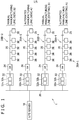
- Fig. 1 is an overall configuration diagram of a manufacturing plant computer system 1 according to the present embodiment.
- the manufacturing plant computer system 1 depicted in Fig. 1 is installed in a manufacturing plant that manufactures information apparatuses such as game consoles and includes a site server 10.
- the site server 10 is a server computer that manages the manufacturing plant computer system 1 as a whole.
- a manufacturing line computer system 30A-1 is in place for the existing automated manufacturing line A1, and a manufacturing line computer system 30B-1 is in place for the existing manual manufacturing line B1. Also, a manufacturing line computer system 30A-2 will be in place for the new automated manufacturing line A2 which will be added, and a manufacturing line computer system 30B-2 will be in place for the new manual manufacturing line B2 which will be added. Both of the automated manufacturing lines A1 and A2 manufacture goods of the same kind through the same processes (robot-based automated processes). Similarly, both of the manual manufacturing lines B1 and B2 manufacture goods of the same kind through the same processes (manual labor-oriented processes).
- the manufacturing line computer system 30A-1 includes a line controller 32 (first computer), a server computer, and a number of plant apparatuses 36 (second computer) that are connected to the line controller 32 via a switching hub 34, thereby forming a manufacturing line network 35.
- the line controller 32 includes a NAT (Network Address Translation) function 32a and a DHCP (Dynamic Host Configuration Protocol) server function 32b.
- the line controller 32 is also connected to the site server 10 via a management network 20.
- Each of the plant apparatuses 36 includes a computer.
- computers incorporated in the plant apparatuses 36 are those connected to robot arms to control the robot arm, those connected to label printers to control the label printers, those for writing data to information apparatuses, manufactured goods, those for recording production logs, those for conducting various inspections, those for controlling conveyors for transporting manufactured goods, those connected to cameras to control the cameras, and those for analyzing camera images.
- Apparatuses adequate for the processes carried out in the automated manufacturing line A1 are employed as the plant apparatuses 36.
- the switching hub 34 supports a subnet-based VLAN (Virtual Local Area Network).
- the subnet-based VLAN ensures that the plant apparatuses 36 that belong to the same subnet belong to the same VLAN. This permits data circulation only within the same VLAN.
- the manufacturing line network 35 may be constituted a single VLAN or a plurality of VLANs. Each of the plant apparatuses 36 belongs to at least one VLAN that is selected to suit the role thereof. As a result, the plant apparatuses 36 having the same role belong to the same VLAN, thereby allowing for efficient circulation of data in the manufacturing line network 35.
- the manufacturing line computer system 30A-2 has the same apparatus configuration as the manufacturing line computer system 30A-1.
- the manual manufacturing line B-1 manufactures the same kind of goods through different processes. Therefore, the manufacturing line computer system 30B-1 has a different configuration from that of the manufacturing line computer system 30A-1.
- the manufacturing line computer systems 30B-1 and 30A-1 are common in that they have the line controller 32 and the switching hub 34, but differ in at least either the number or type of plant apparatuses 36. It should be noted that because both of the manual manufacturing lines B-1 and B-2 manufacture the same kind of goods through the same processes as described above, the manufacturing line computer system 30B-2 has the same apparatus configuration as the manufacturing line computer system 30B-1.
- the line controller 32 includes the NAT function 32a as described above, and as a result, translation of IP (Internet Protocol) addresses takes place between each of the plant apparatuses 36 of the manufacturing line network 35 and the management network 20.
- IP Internet Protocol
- an arbitrary IP address can be specified for each of the plant apparatuses 36 and the line controller 32.
- the same group of IP addresses are specified for the manufacturing line computer systems 30A-1 and 30A-2 by using a template which will be described later.
- the same group of IP addresses are specified for the manufacturing line computer systems 30B-1 and 30B-2.
- the same IP address is specified for the plant apparatuses 36 having the same role.
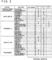
- Figs. 2 and 3 illustrate examples of templates designed for address setup.
- the template depicted in Fig. 2 has been prepared for automated manufacturing lines and applied to the manufacturing line computer systems 30A-1 and 30A-2.
- the template depicted in Fig. 3 has been prepared for manual manufacturing lines and applied to the manufacturing line computer systems 30B-1 and 30B-2.
- a table includes role information and network addresses.
- the role information indicates the role of each of the plant apparatuses 36 (computers) such as "PRODUCTION MANAGING PC 1" and "ROBOT ARM 2.” Although the role information is a descriptive word for ease of comprehension here, it may be one of a variety of symbols.
- a network address includes a host address and a subnet address. VLAN_1, VLAN_2, and VLAN_3 are available for the manufacturing line networks 35 of the automated manufacturing lines. Subnet address "10.1.1” is assigned to VLAN_1, subnet address "10.1.2” is assigned to VLAN_2, and subnet address "10.1.3” is assigned to VLAN_3.
- a circle indicates to which VLAN the plant apparatus 36 with each role belongs.
- the plant apparatus 36 with a role of "PRODUCTION MANAGING PC 1" belongs to VLAN_1, and the subnet address thereof is "10.1.1.” Because the host address of the same plant apparatus 36 is "11,” the network address thereof is “10.1.1.11.” Also, the plant apparatus 36 with a role of "DATA WRITING PC 1" belongs to VLAN_1 and VLAN_2, and the subnet addresses thereof are “10.1.1” and "10.1.2.” Because the host address of the same plant apparatus 36 is "12", the network addresses thereof are "10.1.1.12” and "10.1.2.12.” That is, two network addresses are assigned.
- the table depicted in Fig. 3 has been prepared for manual manufacturing lines and has, therefore, a small number of roles, i.e., plant apparatuses 36. Also, there is only one VLAN.
- the line controller 32 is connected to the management network 20, followed by the connection of the switching hub 34 to the line controller 32, to build the manufacturing line computer system 30A-2.
- the plant apparatuses 36 necessary for the manufacturing line A-2 are arranged and, connected to the switching hub 34.
- a network setup program for line controller is started in the line controller 32.
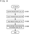
- Fig. 4 is an operational flowchart of this network setup program.
- the line controller accesses the site server 10 first and acquires a manufacturing line list (S101).
- the manufacturing line list is a list of manufacturing line types.
- two types of manufacturing lines namely, "AUTOMATED MANUFACTURING LINE” and "MANUAL MANUFACTURING LINE" are described in the list.
- the line controller 32 displays the manufacturing line list on a display and prompts the user to select a manufacturing line type with an input device such as mouse (S102). Thereafter, the line controller 32 sends the selected manufacturing line type ("AUTOMATED MANUFACTURING LINE" here) to the site server 10 (S103).
- the site server 10 returns the template associated with the type received from the line controller 32 (template for automated manufacturing line depicted in Fig. 2 here), and the line controller 32 receives the template (S104).
- the received template is stored in a local storage device.
- the IP address indicated in the received template is specified in advance for the line controller 32 as its own IP address in the manufacturing line network 35. For example, according to the template depicted in Fig. 2 , IP address "10.1.1.1" is specified for the line controller 32.
- the line controller 32 starts a network setup support program. Also, each of the plant apparatuses 36 starts a plant apparatus network setup program according to an embodiment of the present disclosure.
- Fig. 5 is an operational flowchart of the network setup program executed on the plant apparatuses 36 and the support program executed on the line controller 32. It should be noted that the line controller 32 includes the DHCP function 32b, that a temporary IP address is assigned to each of the plant apparatuses 36 in advance, and that the plant apparatuses 36 can communicate with the line controller 32.
- the plant apparatus 36 acquires its MAC (Media Access Control) address (S201). Also, the plant apparatus 36 displays an input form on its display and prompts the user to input role information regarding the plant apparatus 36 by using physical keys, a touch panel, and so on (S202). Thereafter, the plant apparatus 36 sends the MAC address and role information to the line controller 32 (S203) from the plant apparatus 36.
- MAC Media Access Control
- the line controller 32 acquires the IP address associated with the received role information (S204) from the template. Also, the line controller 32 changes the IP address, already stored in association with the received MAC address, into the IP address received in S204 (S205). Then, the line controller 32 sends a request to update the IP address to the plant apparatus 36 (S206). The plant apparatus 36 receives the changed IP address from the line controller 32 in response to this update request and changes its own IP address (S207).
- the embodiment described above allows for identification of a template based on the manufacturing line type and specification of an IP address for the line controller 32 and the plant apparatuses 36 according to the specified template. This ensures simple and reliable specification of IP addresses. Moreover, when a plurality of manufacturing lines are of the same type, the same group of IP addresses are assigned to the line controller 32 and the plant apparatuses 36, thereby facilitating network maintenance tasks.
- the support program of the line controller 32 may decide whether or not IP addresses have been assigned to the plant apparatuses 36 having all the roles described in the template and depict the decision result on an output device such as display. This makes it possible to reliably decide whether or not all the plant apparatuses 36 are in place at the manufacturing line A2 and have been set up for networking.
Landscapes
- Engineering & Computer Science (AREA)
- Computer Networks & Wireless Communication (AREA)
- Signal Processing (AREA)
- Business, Economics & Management (AREA)
- General Physics & Mathematics (AREA)
- Physics & Mathematics (AREA)
- Manufacturing & Machinery (AREA)
- Quality & Reliability (AREA)
- Economics (AREA)
- Strategic Management (AREA)
- Theoretical Computer Science (AREA)
- General Business, Economics & Management (AREA)
- Human Resources & Organizations (AREA)
- Marketing (AREA)
- Tourism & Hospitality (AREA)
- General Engineering & Computer Science (AREA)
- Automation & Control Theory (AREA)
- General Health & Medical Sciences (AREA)
- Primary Health Care (AREA)
- Computer Security & Cryptography (AREA)
- Health & Medical Sciences (AREA)
- Entrepreneurship & Innovation (AREA)
- Operations Research (AREA)
- General Factory Administration (AREA)
- Small-Scale Networks (AREA)
Abstract
Description
- The present disclosure relates to a manufacturing line computer system and a network setup method thereof, and more particularly, to setup of a computer system network arranged along manufacturing lines.
- Recent years have seen a number of computers arranged along manufacturing lines in manufacturing plants that manufacture a variety of goods. Some of these computers are connected, for example, to manufacturing robots to control these robots, others are used to record production logs of goods, and still others are used to write necessary data to information apparatuses, manufactured goods. These computers are connected to a network for communication with other computers as occasion demand.
- At the time of erection of manufacturing lines and addition of new lines, it is necessary to arrange a number of computers along the manufacturing lines as described above and set up each computer for networking correctly so that data communication can be exchanged between the computers as intended. However, this task is often complicated and time-consuming.
- The present disclosure has been devised in light of the foregoing, and it is desirable to provide a manufacturing line computer system and a network setup method thereof that allow for easy and reliable network setup of computers arranged along manufacturing lines.
- According to an embodiment of the present disclosure, there is provided a manufacturing line computer system that includes first and second computers. The first computer includes a storage section and a reply section. The storage section stores a template that associates role information of the second computer and a network address of the second computer. The reply section returns the network address of the second computer associated with the role information to the second computer in response to reception of the role information from the second computer. The second computer includes an input section, a transmission section, and a network address setup section. The input section inputs the role information of the second computer. The transmission section sends the input role information of the second computer to the first computer. The network address setup section specifies the network address returned from the first computer, for the second computer.
- According to another embodiment of the present disclosure, there is provided a network setup method of a manufacturing line computer system. The manufacturing line computer system includes first and second computers. The network setup method includes a step of inputting role information of the second computer to the second computer. The network setup method further includes a step of sending the input role information of the second computer from the second computer to the first computer. The network setup method still further includes a step of referring to a template that associates role information of the second computer and a network address of the second computer on the first computer and acquiring the network address of the second computer associated with the received role information. The network setup method still further includes a step of returning the acquired network address of the second computer to the second computer. The network setup method still further includes a step of specifying the network address, returned from the first computer, for the second computer.
-
-
Fig. 1 is an overall configuration diagram of a manufacturing plant computer system according to an embodiment of the present disclosure; -
Fig. 2 is a diagram illustrating an example of a template used to specify addresses for apparatuses of a manufacturing line computer system; -
Fig. 3 is a diagram illustrating another example of a template used to specify addresses for apparatuses of the manufacturing line computer system; -
Fig. 4 is a flowchart illustrating a network setup program executed on a line controller; and -
Fig. 5 is a flowchart illustrating processes of a network setup program executed on the plant apparatuses and processes of a support program executed on the line controller. - A detailed description will be given below of an embodiment of the present disclosure with reference to drawings.
-
Fig. 1 is an overall configuration diagram of a manufacturingplant computer system 1 according to the present embodiment. The manufacturingplant computer system 1 depicted inFig. 1 is installed in a manufacturing plant that manufactures information apparatuses such as game consoles and includes asite server 10. Thesite server 10 is a server computer that manages the manufacturingplant computer system 1 as a whole. - There are provided, for example, four manufacturing lines in this manufacturing plant. We assume here that an automated manufacturing line A1 and a manual manufacturing line B1 are in place as existing manufacturing line. We also assume that an automated manufacturing line A2 and a manual manufacturing line B2 will be newly added.
- A manufacturing
line computer system 30A-1 is in place for the existing automated manufacturing line A1, and a manufacturingline computer system 30B-1 is in place for the existing manual manufacturing line B1. Also, a manufacturingline computer system 30A-2 will be in place for the new automated manufacturing line A2 which will be added, and a manufacturingline computer system 30B-2 will be in place for the new manual manufacturing line B2 which will be added. Both of the automated manufacturing lines A1 and A2 manufacture goods of the same kind through the same processes (robot-based automated processes). Similarly, both of the manual manufacturing lines B1 and B2 manufacture goods of the same kind through the same processes (manual labor-oriented processes). - The manufacturing
line computer system 30A-1 includes a line controller 32 (first computer), a server computer, and a number of plant apparatuses 36 (second computer) that are connected to theline controller 32 via aswitching hub 34, thereby forming amanufacturing line network 35. Theline controller 32 includes a NAT (Network Address Translation)function 32a and a DHCP (Dynamic Host Configuration Protocol)server function 32b. Theline controller 32 is also connected to thesite server 10 via amanagement network 20. - Each of the
plant apparatuses 36 includes a computer. Among examples of computers incorporated in theplant apparatuses 36 are those connected to robot arms to control the robot arm, those connected to label printers to control the label printers, those for writing data to information apparatuses, manufactured goods, those for recording production logs, those for conducting various inspections, those for controlling conveyors for transporting manufactured goods, those connected to cameras to control the cameras, and those for analyzing camera images. Apparatuses adequate for the processes carried out in the automated manufacturing line A1 are employed as theplant apparatuses 36. - The
switching hub 34 supports a subnet-based VLAN (Virtual Local Area Network). The subnet-based VLAN ensures that theplant apparatuses 36 that belong to the same subnet belong to the same VLAN. This permits data circulation only within the same VLAN. Themanufacturing line network 35 may be constituted a single VLAN or a plurality of VLANs. Each of theplant apparatuses 36 belongs to at least one VLAN that is selected to suit the role thereof. As a result, theplant apparatuses 36 having the same role belong to the same VLAN, thereby allowing for efficient circulation of data in themanufacturing line network 35. - As described above, both the automated manufacturing lines A1 and A2 manufacture the same kind of goods through the same processes. Therefore, the manufacturing
line computer system 30A-2 has the same apparatus configuration as the manufacturingline computer system 30A-1. On the other hand, the manual manufacturing line B-1 manufactures the same kind of goods through different processes. Therefore, the manufacturingline computer system 30B-1 has a different configuration from that of the manufacturingline computer system 30A-1. Specifically, the manufacturingline computer systems 30B-1 and 30A-1 are common in that they have theline controller 32 and theswitching hub 34, but differ in at least either the number or type ofplant apparatuses 36. It should be noted that because both of the manual manufacturing lines B-1 and B-2 manufacture the same kind of goods through the same processes as described above, the manufacturingline computer system 30B-2 has the same apparatus configuration as the manufacturingline computer system 30B-1. - The
line controller 32 includes theNAT function 32a as described above, and as a result, translation of IP (Internet Protocol) addresses takes place between each of theplant apparatuses 36 of themanufacturing line network 35 and themanagement network 20. In each of themanufacturing line networks 35, therefore, an arbitrary IP address can be specified for each of theplant apparatuses 36 and theline controller 32. Here, the same group of IP addresses are specified for the manufacturingline computer systems 30A-1 and 30A-2 by using a template which will be described later. Similarly, the same group of IP addresses are specified for the manufacturingline computer systems 30B-1 and 30B-2. Specifically, the same IP address is specified for theplant apparatuses 36 having the same role. -
Figs. 2 and3 illustrate examples of templates designed for address setup. The template depicted inFig. 2 has been prepared for automated manufacturing lines and applied to the manufacturingline computer systems 30A-1 and 30A-2. The template depicted inFig. 3 has been prepared for manual manufacturing lines and applied to the manufacturingline computer systems 30B-1 and 30B-2. - As depicted in
Fig. 2 , a table includes role information and network addresses. The role information indicates the role of each of the plant apparatuses 36 (computers) such as "PRODUCTION MANAGING PC 1" and "ROBOT ARM 2." Although the role information is a descriptive word for ease of comprehension here, it may be one of a variety of symbols. A network address includes a host address and a subnet address. VLAN_1, VLAN_2, and VLAN_3 are available for themanufacturing line networks 35 of the automated manufacturing lines. Subnet address "10.1.1" is assigned to VLAN_1, subnet address "10.1.2" is assigned to VLAN_2, and subnet address "10.1.3" is assigned to VLAN_3. In the template, a circle indicates to which VLAN theplant apparatus 36 with each role belongs. For example, theplant apparatus 36 with a role of "PRODUCTION MANAGING PC 1" belongs to VLAN_1, and the subnet address thereof is "10.1.1." Because the host address of thesame plant apparatus 36 is "11," the network address thereof is "10.1.1.11." Also, theplant apparatus 36 with a role of "DATA WRITING PC 1" belongs to VLAN_1 and VLAN_2, and the subnet addresses thereof are "10.1.1" and "10.1.2." Because the host address of thesame plant apparatus 36 is "12", the network addresses thereof are "10.1.1.12" and "10.1.2.12." That is, two network addresses are assigned. - In contrast, the table depicted in
Fig. 3 has been prepared for manual manufacturing lines and has, therefore, a small number of roles, i.e., plant apparatuses 36. Also, there is only one VLAN. - A description will be given here of building of a system according to the present embodiment by taking, as an example, tasks undertaken to build the manufacturing
line computer system 30A-2 for the automated manufacturing line A2. Theline controller 32 is connected to themanagement network 20, followed by the connection of the switchinghub 34 to theline controller 32, to build the manufacturingline computer system 30A-2. Further, the plant apparatuses 36 necessary for the manufacturing line A-2 are arranged and, connected to the switchinghub 34. - Next, a network setup program for line controller according to an embodiment of the present disclosure is started in the
line controller 32.Fig. 4 is an operational flowchart of this network setup program. As depicted inFig. 4 , when the network setup program is started, the line controller accesses thesite server 10 first and acquires a manufacturing line list (S101). The manufacturing line list is a list of manufacturing line types. Here, two types of manufacturing lines, namely, "AUTOMATED MANUFACTURING LINE" and "MANUAL MANUFACTURING LINE" are described in the list. - Next, the
line controller 32 displays the manufacturing line list on a display and prompts the user to select a manufacturing line type with an input device such as mouse (S102). Thereafter, theline controller 32 sends the selected manufacturing line type ("AUTOMATED MANUFACTURING LINE" here) to the site server 10 (S103). - The
site server 10 returns the template associated with the type received from the line controller 32 (template for automated manufacturing line depicted inFig. 2 here), and theline controller 32 receives the template (S104). The received template is stored in a local storage device. It should be noted that the IP address indicated in the received template is specified in advance for theline controller 32 as its own IP address in themanufacturing line network 35. For example, according to the template depicted inFig. 2 , IP address "10.1.1.1" is specified for theline controller 32. - Thereafter, the
line controller 32 starts a network setup support program. Also, each of the plant apparatuses 36 starts a plant apparatus network setup program according to an embodiment of the present disclosure.Fig. 5 is an operational flowchart of the network setup program executed on the plant apparatuses 36 and the support program executed on theline controller 32. It should be noted that theline controller 32 includes theDHCP function 32b, that a temporary IP address is assigned to each of the plant apparatuses 36 in advance, and that the plant apparatuses 36 can communicate with theline controller 32. - As illustrated in
Fig. 5 , when the plant apparatus network setup program is started in theplant apparatus 36, theplant apparatus 36 acquires its MAC (Media Access Control) address (S201). Also, theplant apparatus 36 displays an input form on its display and prompts the user to input role information regarding theplant apparatus 36 by using physical keys, a touch panel, and so on (S202). Thereafter, theplant apparatus 36 sends the MAC address and role information to the line controller 32 (S203) from theplant apparatus 36. - Because of the support program, the
line controller 32 acquires the IP address associated with the received role information (S204) from the template. Also, theline controller 32 changes the IP address, already stored in association with the received MAC address, into the IP address received in S204 (S205). Then, theline controller 32 sends a request to update the IP address to the plant apparatus 36 (S206). Theplant apparatus 36 receives the changed IP address from theline controller 32 in response to this update request and changes its own IP address (S207). - The embodiment described above allows for identification of a template based on the manufacturing line type and specification of an IP address for the
line controller 32 and the plant apparatuses 36 according to the specified template. This ensures simple and reliable specification of IP addresses. Moreover, when a plurality of manufacturing lines are of the same type, the same group of IP addresses are assigned to theline controller 32 and the plant apparatuses 36, thereby facilitating network maintenance tasks. - It should be noted that the support program of the
line controller 32 may decide whether or not IP addresses have been assigned to the plant apparatuses 36 having all the roles described in the template and depict the decision result on an output device such as display. This makes it possible to reliably decide whether or not all the plant apparatuses 36 are in place at the manufacturing line A2 and have been set up for networking. - The present disclosure contains subject matter related to that disclosed in Japanese Priority Patent Application
JP 2017-093603 - It should be understood by those skilled in the art that various modifications, combinations, subcombinations and alterations may occur depending on design requirements and other factors insofar as they are within the scope of the appended claims or the equivalent thereof.
Claims (6)
- A manufacturing line computer system comprising:first and second computers, whereinthe first computer includesa storage section adapted to store a template that associates role information of the second computer and a network address of the second computer; anda reply section adapted to return the network address of the second computer associated with the role information to the second computer in response to reception of the role information from the second computer, andthe second computer includesan input section adapted to input the role information of the second computer;a transmission section adapted to send the input role information of the second computer to the first computer; anda network address setup section adapted to specify the network address, returned from the first computer, for the second computer.
- The manufacturing line computer system of claim 1, wherein
the storage section further stores a network address of the first computer, and
the first computer specifies the network address of the first computer, stored in the storage section, for the first computer. - The manufacturing line computer system of claim 1 or 2, wherein
the first computer is connected to an upstream network via network address translation. - The manufacturing line computer system of any one of claims 1 to 3, wherein
the second computer is connected to the first computer via a switching hub that supports a subnet-based virtual local area network, and
a subnet address adequate for role information thereof is assigned to the second computer. - The manufacturing line computer system of any one of claims 1 to 4, wherein
the first computer receives, of a plurality of templates, one associated with the type of the manufacturing line where the first and second computers are arranged. - A network setup method of a manufacturing line computer system, the manufacturing line computer system including first and second computers, the network setup method comprising:inputting role information of the second computer to the second computer;sending the input role information of the second computer from the second computer to the first computer;referring to a template that associates role information of the second computer and a network address of the second computer on the first computer and acquiring the network address of the second computer associated with the received role information;returning the acquired network address of the second computer to the second computer; andspecifying the network address, returned from the first computer, for the second computer.
Applications Claiming Priority (1)
| Application Number | Priority Date | Filing Date | Title |
|---|---|---|---|
| JP2017093603A JP6585656B2 (en) | 2017-05-10 | 2017-05-10 | Computer system for production line and network setting method thereof |
Publications (1)
| Publication Number | Publication Date |
|---|---|
| EP3402171A1 true EP3402171A1 (en) | 2018-11-14 |
Family
ID=62165307
Family Applications (1)
| Application Number | Title | Priority Date | Filing Date |
|---|---|---|---|
| EP18168891.2A Ceased EP3402171A1 (en) | 2017-05-10 | 2018-04-24 | Manufacturing line computer system and network setup method of the same |
Country Status (4)
| Country | Link |
|---|---|
| US (2) | US11063901B2 (en) |
| EP (1) | EP3402171A1 (en) |
| JP (1) | JP6585656B2 (en) |
| CN (1) | CN108873827B (en) |
Families Citing this family (6)
| Publication number | Priority date | Publication date | Assignee | Title |
|---|---|---|---|---|
| JP6585656B2 (en) * | 2017-05-10 | 2019-10-02 | 株式会社ソニー・インタラクティブエンタテインメント | Computer system for production line and network setting method thereof |
| JP7392428B2 (en) * | 2019-11-29 | 2023-12-06 | セイコーエプソン株式会社 | Robot system control method |
| TWI861445B (en) * | 2020-12-08 | 2024-11-11 | 日商發那科股份有限公司 | Robot control device, robot control system and robot control method |
| JP7548883B2 (en) * | 2021-09-07 | 2024-09-10 | 株式会社小松製作所 | Industrial machine identification system, industrial machine identification method, and industrial machine identification device |
| CN114221936B (en) * | 2021-12-07 | 2024-12-20 | 中国电信股份有限公司 | Address allocation method, system, terminal, and address allocation platform |
| SE2230242A1 (en) | 2022-07-18 | 2023-06-07 | Atlas Copco Ind Technique Ab | Method of a network device for connecting a group of industrial tools to a plurality of controllers using shared single virtual ip addresses and identifiers, and network device |
Citations (6)
| Publication number | Priority date | Publication date | Assignee | Title |
|---|---|---|---|---|
| WO2001086906A2 (en) * | 2000-05-12 | 2001-11-15 | Solutioninc Limited | Server and method for providing specific network services |
| US6873602B1 (en) * | 1999-08-06 | 2005-03-29 | Fujitsu Limited | Network system, switch, and server |
| US20070081541A1 (en) * | 2003-09-22 | 2007-04-12 | Sharp Kabushiki Kaisha | Line concentrator, relay control method, relay control program, storage medium storing the relay control program, information processing device, dhcp server, dhcp processing method, dhcp processing program, storage medium storing the dhcp processing program and information processing system |
| US20130044636A1 (en) * | 2011-08-17 | 2013-02-21 | Teemu Koponen | Distributed logical l3 routing |
| US20130201978A1 (en) * | 2012-02-06 | 2013-08-08 | Pradeep Iyer | Method and System for Partitioning Wireless Local Area Network |
| JP2017093603A (en) | 2015-11-19 | 2017-06-01 | 株式会社ニューギン | Game machine |
Family Cites Families (26)
| Publication number | Priority date | Publication date | Assignee | Title |
|---|---|---|---|---|
| US6453210B1 (en) * | 1998-07-23 | 2002-09-17 | Vulcan Engineering Company, Inc. | Autonomous control method and process for an investment casting shell |
| JP3823929B2 (en) | 2002-05-17 | 2006-09-20 | ソニー株式会社 | Information processing apparatus, information processing method, content distribution apparatus, content distribution method, and computer program |
| JP2007221553A (en) * | 2006-02-17 | 2007-08-30 | Yaskawa Electric Corp | Plant equipment operation system |
| JP4755548B2 (en) * | 2006-08-01 | 2011-08-24 | 株式会社日立製作所 | Operation management method, operation management program, operation management system, and operation management apparatus |
| CN101424941B (en) | 2007-10-31 | 2011-05-25 | 北京北方微电子基地设备工艺研究中心有限责任公司 | Control implementing method and system |
| EP2075659A1 (en) * | 2007-12-31 | 2009-07-01 | Tetra Laval Holdings & Finance SA | Integrated packaging system architecture |
| WO2011003200A1 (en) * | 2009-07-10 | 2011-01-13 | Certicom Corp. | System and method for performing key injection to devices |
| KR20120000171A (en) | 2010-06-25 | 2012-01-02 | 주식회사 케이티 | Virtual private communication system and processing method having same subscriber address processing function |
| US8689184B2 (en) * | 2011-03-30 | 2014-04-01 | The Procter & Gamble Company | Apparatus, system, and method for managing industrial software configurations |
| CN109634198B (en) * | 2011-10-05 | 2021-06-22 | 奥普唐公司 | Method, apparatus and system for monitoring and/or generating dynamic environments |
| US9201704B2 (en) | 2012-04-05 | 2015-12-01 | Cisco Technology, Inc. | System and method for migrating application virtual machines in a network environment |
| US20180096175A1 (en) * | 2016-10-01 | 2018-04-05 | James L. Schmeling | Blockchain Enabled Packaging |
| EP2879060B1 (en) * | 2013-10-23 | 2017-05-31 | Huawei Technologies Co., Ltd. | Cloud application disaster recovery method, system and device |
| US9489654B2 (en) * | 2014-03-14 | 2016-11-08 | Airbus Operations Sas | Artificial intelligence system and method for processing multilevel bills of materials |
| US9843617B2 (en) * | 2014-03-26 | 2017-12-12 | Rockwell Automation Technologies, Inc. | Cloud manifest configuration management system |
| US9338092B1 (en) * | 2014-06-20 | 2016-05-10 | Amazon Technologies, Inc. | Overlay networks for application groups |
| CN104570739B (en) * | 2015-01-07 | 2017-01-25 | 东北大学 | Ore dressing multi-production-index optimized decision making system and method based on cloud and mobile terminal |
| US9838302B1 (en) * | 2015-06-10 | 2017-12-05 | Amazon Technologies, Inc. | Managing loss of network connectivity in traffic forwarding systems |
| CN104951888A (en) | 2015-06-24 | 2015-09-30 | 北京京东尚科信息技术有限公司 | Method and system for processing order picking information |
| US10764294B1 (en) * | 2016-03-10 | 2020-09-01 | Amazon Technologies, Inc. | Data exfiltration control |
| JP6623869B2 (en) * | 2016-03-16 | 2019-12-25 | 株式会社リコー | Device management system, device management device, program, and device management method |
| CN107305372B (en) * | 2016-04-25 | 2020-06-19 | 岳秀兰 | Electric automobile energy monitoring and supply network for remote monitoring of cloud computing network architecture |
| US10469324B2 (en) * | 2016-11-22 | 2019-11-05 | Amazon Technologies, Inc. | Virtual network verification service |
| US10791089B2 (en) * | 2017-03-29 | 2020-09-29 | Hewlett Packard Enterprise Development Lp | Converged address translation |
| JP6585656B2 (en) * | 2017-05-10 | 2019-10-02 | 株式会社ソニー・インタラクティブエンタテインメント | Computer system for production line and network setting method thereof |
| US10432467B2 (en) * | 2017-06-19 | 2019-10-01 | Cisco Technology, Inc. | Network validation between the logical level and the hardware level of a network |
-
2017
- 2017-05-10 JP JP2017093603A patent/JP6585656B2/en active Active
-
2018
- 2018-04-24 US US15/961,052 patent/US11063901B2/en active Active
- 2018-04-24 EP EP18168891.2A patent/EP3402171A1/en not_active Ceased
- 2018-05-03 CN CN201810413149.0A patent/CN108873827B/en active Active
-
2021
- 2021-06-10 US US17/344,353 patent/US11310196B2/en active Active
Patent Citations (6)
| Publication number | Priority date | Publication date | Assignee | Title |
|---|---|---|---|---|
| US6873602B1 (en) * | 1999-08-06 | 2005-03-29 | Fujitsu Limited | Network system, switch, and server |
| WO2001086906A2 (en) * | 2000-05-12 | 2001-11-15 | Solutioninc Limited | Server and method for providing specific network services |
| US20070081541A1 (en) * | 2003-09-22 | 2007-04-12 | Sharp Kabushiki Kaisha | Line concentrator, relay control method, relay control program, storage medium storing the relay control program, information processing device, dhcp server, dhcp processing method, dhcp processing program, storage medium storing the dhcp processing program and information processing system |
| US20130044636A1 (en) * | 2011-08-17 | 2013-02-21 | Teemu Koponen | Distributed logical l3 routing |
| US20130201978A1 (en) * | 2012-02-06 | 2013-08-08 | Pradeep Iyer | Method and System for Partitioning Wireless Local Area Network |
| JP2017093603A (en) | 2015-11-19 | 2017-06-01 | 株式会社ニューギン | Game machine |
Also Published As
| Publication number | Publication date |
|---|---|
| CN108873827B (en) | 2022-01-21 |
| US11310196B2 (en) | 2022-04-19 |
| US20180332002A1 (en) | 2018-11-15 |
| JP6585656B2 (en) | 2019-10-02 |
| JP2018191199A (en) | 2018-11-29 |
| US20210306297A1 (en) | 2021-09-30 |
| US11063901B2 (en) | 2021-07-13 |
| CN108873827A (en) | 2018-11-23 |
Similar Documents
| Publication | Publication Date | Title |
|---|---|---|
| US11310196B2 (en) | Manufacturing line computer system and network setup method of the same | |
| CN104753697B (en) | A method, device and system for controlling automatic deployment of network devices | |
| US10129096B2 (en) | Commissioning/decommissioning networks in orchestrated or software-defined computing environments | |
| CN101090324B (en) | network system and server | |
| US20200076703A1 (en) | Iot cloud to cloud architecture | |
| CN110633175B (en) | Multi-computer-room data processing method based on micro-service, electronic equipment and storage medium | |
| CN114584504B (en) | Network card communication method, device, equipment and medium for AI training platform | |
| EP2499784A2 (en) | Model-based virtual networking | |
| US20130131885A1 (en) | System and method for obtaining and managing temperature data | |
| USRE46770E1 (en) | Computer managing method | |
| EP3860050B1 (en) | Commissioning/decommissioning networks in software-defined computing environments | |
| CN105791240A (en) | Multichannel and multiprotocol channel management method and system | |
| CN104219097B (en) | A kind of quickly configuration method of distributed system | |
| EP4014472B1 (en) | Multi-headed web-application architecture and messaging structure | |
| US20180069829A1 (en) | Automatic discovery of management server ip address using dhcp for thin client solution | |
| US9509656B2 (en) | Broadcast distribution table for BACnet/IP | |
| CN104735147A (en) | Electronic seat number implementation method | |
| US20080232370A1 (en) | Method of communication in LAN without setting IP | |
| CN107800810A (en) | A kind of Server remote control method and system | |
| CN108848200A (en) | Equipment adding method, device, equipment and medium in a kind of local area network | |
| US9634987B2 (en) | Obtaining a MAC address from an external source | |
| JP5176482B2 (en) | Management program, management method, management apparatus, and communication system | |
| US20070121577A1 (en) | Physical wiring control device, physical wiring control method, and computer product | |
| CN102904776A (en) | Detection method, device and equipment in virtual local area network | |
| CN112532460A (en) | Server configuration method, device, equipment and computer readable storage medium |
Legal Events
| Date | Code | Title | Description |
|---|---|---|---|
| PUAI | Public reference made under article 153(3) epc to a published international application that has entered the european phase |
Free format text: ORIGINAL CODE: 0009012 |
|
| STAA | Information on the status of an ep patent application or granted ep patent |
Free format text: STATUS: REQUEST FOR EXAMINATION WAS MADE |
|
| 17P | Request for examination filed |
Effective date: 20180522 |
|
| AK | Designated contracting states |
Kind code of ref document: A1 Designated state(s): AL AT BE BG CH CY CZ DE DK EE ES FI FR GB GR HR HU IE IS IT LI LT LU LV MC MK MT NL NO PL PT RO RS SE SI SK SM TR |
|
| AX | Request for extension of the european patent |
Extension state: BA ME |
|
| STAA | Information on the status of an ep patent application or granted ep patent |
Free format text: STATUS: EXAMINATION IS IN PROGRESS |
|
| 17Q | First examination report despatched |
Effective date: 20200113 |
|
| STAA | Information on the status of an ep patent application or granted ep patent |
Free format text: STATUS: THE APPLICATION HAS BEEN REFUSED |
|
| 18R | Application refused |
Effective date: 20210504 |