EP3402085A1 - Techniques for compensating time delay difference in beamformed transmission - Google Patents
Techniques for compensating time delay difference in beamformed transmission Download PDFInfo
- Publication number
- EP3402085A1 EP3402085A1 EP17170640.1A EP17170640A EP3402085A1 EP 3402085 A1 EP3402085 A1 EP 3402085A1 EP 17170640 A EP17170640 A EP 17170640A EP 3402085 A1 EP3402085 A1 EP 3402085A1
- Authority
- EP
- European Patent Office
- Prior art keywords
- time delay
- transmit chain
- synchronizer
- transmission
- transmitter device
- Prior art date
- Legal status (The legal status is an assumption and is not a legal conclusion. Google has not performed a legal analysis and makes no representation as to the accuracy of the status listed.)
- Withdrawn
Links
Images

Classifications
-
- H—ELECTRICITY
- H04—ELECTRIC COMMUNICATION TECHNIQUE
- H04B—TRANSMISSION
- H04B7/00—Radio transmission systems, i.e. using radiation field
- H04B7/02—Diversity systems; Multi-antenna system, i.e. transmission or reception using multiple antennas
- H04B7/04—Diversity systems; Multi-antenna system, i.e. transmission or reception using multiple antennas using two or more spaced independent antennas
- H04B7/06—Diversity systems; Multi-antenna system, i.e. transmission or reception using multiple antennas using two or more spaced independent antennas at the transmitting station
- H04B7/0613—Diversity systems; Multi-antenna system, i.e. transmission or reception using multiple antennas using two or more spaced independent antennas at the transmitting station using simultaneous transmission
- H04B7/0615—Diversity systems; Multi-antenna system, i.e. transmission or reception using multiple antennas using two or more spaced independent antennas at the transmitting station using simultaneous transmission of weighted versions of same signal
- H04B7/0617—Diversity systems; Multi-antenna system, i.e. transmission or reception using multiple antennas using two or more spaced independent antennas at the transmitting station using simultaneous transmission of weighted versions of same signal for beam forming
-
- H—ELECTRICITY
- H04—ELECTRIC COMMUNICATION TECHNIQUE
- H04W—WIRELESS COMMUNICATION NETWORKS
- H04W56/00—Synchronisation arrangements
- H04W56/001—Synchronization between nodes
Definitions
- the disclosure relates to a transmitter device and a beamforming transmitter device with time delay filter compensating for a time delay difference resulting from synchronizing.
- the disclosure relates to time delay synchronization of multiple transmit chains for multiple-input multiple-output (MIMO) communication in the scenario of transmit (Tx) Beamforming for Time Division Duplexing (TDD) deployment.
- MIMO multiple-input multiple-output
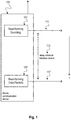
- Figure 1 shows a mobile communication device 100 for MIMO communication in the scenario of Tx beamforming with a transmit chain for beamforming sounding 101 that transmits a sounding packet 111 and a transmit chain for beamforming data packets 103 that transmits data packets 112. Due to synchronization of the chains 101, 103 there occurs a delay variance 113 between the chains 101, 103, i.e. a different total delay of each chain 101, 103. This different delay degrades the beamforming performance. There is a need for a concept to improve beamforming performance in the above described scenario.
- a corresponding device configured to perform the method and vice versa.
- a corresponding device may include a unit to perform the described method step, even if such a unit is not explicitly described or illustrated in the figures.
- the features of the various exemplary aspects described herein may be combined with each other, unless specifically noted otherwise.
- the methods and devices described herein may be implemented in wireless communication networks, in particular communication networks based on connectivity standards, in particular high speed standards from the 802.11 family e.g. 802.11ad and successor standards.
- the methods are also applicable for mobile communication standards such as LTE, in particular LTE-A and/or OFDM and successor standards such as 5G.
- the methods and devices described below may be implemented in electronic devices, in particular electronic circuits of mobile communication devices, mobile terminals, stations and UEs.
- the described devices may include integrated circuits and/or passives and may be manufactured according to various technologies.
- the circuits may be designed as logic integrated circuits, analog integrated circuits, mixed signal integrated circuits, optical circuits, memory circuits and/or integrated passives.
- Beamforming also referred to as spatial filtering is a signal processing technique used in sensor arrays and antenna arrays for directional signal transmission or reception. This is achieved by combining elements in a phased array in such a way that signals at particular angles experience constructive interference while others experience destructive interference. Beamforming can be used at both the transmitting and receiving ends in order to achieve spatial selectivity. The improvement compared with omnidirectional reception/transmission is known as the directivity of the element.
- the 802.11n standard defines a few methods of beamforming.
- explicit beamforming requires the downstream channel to be measured at the receiver, or beamformee, and relayed back to the transmitter, or beamformer.
- the beamformer uses the measured channel information to derive the transmit beamforming parameters.
- TxBF transmit beamforming
- CSI channel state information
- Time-division duplexing is the application of time-division multiplexing to separate outward and return signals. It emulates full duplex communication over a half-duplex communication link.
- Time-division duplexing has a strong advantage in the case where there is asymmetry of the uplink and downlink data rates. As the amount of uplink data increases, more communication capacity can be dynamically allocated, and as the traffic load becomes lighter, capacity can be taken away. The same applies in the downlink direction. For radio systems that are not moving quickly, another advantage is that the uplink and downlink radio paths are likely to be very similar. This means that techniques such as beamforming work well with TDD systems.
- a fractional delay filter is a digital filter which main function is to delay a processed input signal for a fractional of the sampling period time.
- fractional delay filtering There are two main design approaches in fractional delay filtering which are time-domain and frequency-domain design methods.
- time-domain design the fractional delay filter coefficients are obtained by mathematical interpolation formulas, but there is a small flexibility to meet frequency-domain specifications.
- frequency-domain design methods are based on frequency optimization, and a more frequency specification control is available. Frequency-domain methods have a highly efficient implementation structure, which allows online fractional value update.
- Time-to-digital converters also referred to as time digitizers are devices that are used to measure a time interval and to convert it into a digital (e.g. binary) output.
- TDCs are used, for example, in applications, where the time interval between two signal pulses (e.g. a start pulse and a stop pulse) shall be determined. Measurement is started and stopped, when either of the rising or the falling edge of a signal pulse crosses a predetermined threshold.
- Radio signals may be or may include radio frequency signals radiated by a radio transmitting device (or radio transmitter or sender) with a radio frequency lying in a range of about 3 kHz to 300 GHz.
- the frequency range may correspond to frequencies of alternating current electrical signals used to produce and detect radio waves.
- OFDM is a scheme for encoding digital data on multiple carrier frequencies.
- a large number of closely spaced orthogonal sub-carrier signals may be used to carry data. Due to the orthogonality of the sub-carriers crosstalk between sub-carriers may be suppressed.
- MIMO multiple-input multiple-output
- a diversity receiver uses two or more antennas to improve the quality and reliability of a wireless link.
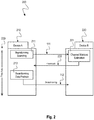
- Fig. 2 is a schematic diagram illustrating a beamforming flow 200 between two communication devices 210, 220.
- the device 210 performing Tx BF 213 is the same device 210 that transmits the sounding packet 111.
- Device A, 210 sends a sounding packet 111 to device B, 220.
- Device B, 220 transmits the CSI or beamforming weights as feedback 222 to device A, 210.
- Device A, 210 uses the feedback 222 to transmit a packet 112 with Tx BF 213 to device B, 220.
- the channel remains the same between the time 230 the sounding packet 111 is sent and the time 230 the beamformed packet 112 is sent.
- the time delay variation between transmit chains for sending the sounding packet 111 and sending the beamformed packet 112 is compensated, i.e. the different delay inside the synchronizer (which implies different total delay of each chain) in packet A (sounding) relative to packet B (beamforming) is compensated.
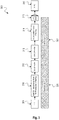
- Fig. 3 is a block diagram of a WiFi transmit chain 300 operating at two clock domains 301, 302 with a synchronizer 312 in between.
- the transmit chain 300 includes the following blocks 309, 310, 312, 313, 314, 315, 316 described as follows.
- a Fast Fourier Transform (FFT) block 309 provides a transmit signal in frequency domain.
- a second block 310 adds a guard interval (GI) to the transmit signal, applies an interpolation chain, performs peak-to-average power reduction (PAPR) and filtering.
- the first two blocks 309, 310 operate at a first clock domain while the following blocks 313, 314, 315 operate at a second clock domain.
- FFT Fast Fourier Transform
- GI guard interval
- PAPR peak-to-average power reduction
- a third block 312 is a synchronizer for synchronizing the WiFi transmit chain 300 between operation at the first clock domain 301 and operation at the second clock domain 302.
- a fourth block 313 is a rate converter to convert the rate of the transmit signal synchronized by the synchronizer 312 from a first rate to a second rate.
- a fifth block 314 is an interpolation chain and filtering block for interpolating and filtering the rate-converted transmit signal which is then output to a high-speed digital-to-analog converter (DAC) 315 and forwarded to a radio frequency integrated circuit (RFIC) for transmission over a radio channel.
- DAC digital-to-analog converter
- the time delay between multiple transmit chains for sounding packet 111 and data packet 112 should be the same. This is not happening in the WiFi Tx chain.
- the Tx chain 300 is active during transmit and disabled (including clocks for power save) during receive.
- the WiFi transmit chain 300 includes different clock domains 301, 302 and synchronizers 312 between them.
- the delay of the synchronizer 312 is random up to +/-1 Tclock per activation. Since delay of every chain is random up to the uncertainty of the synchronizer 312, the delay between Tx chains is random between activations. Not constant time delay between multiple transmit chains during sounding packet 111 and data packet 112 will significantly degrade beamforming gain.
- the concept according to the disclosure is to measure the delay of Transmit chain 300 and correct it on the fly, in order to obtain full beamforming gain of high BW signals. This approach enables to obtain full beamforming gain for high BW signals.
- the delay of synchronizer can be measured during the calibration packet, i.e. the sounding packet, and the data packet and the difference can be corrected on the fly, e.g. by using a dedicated fractional delay filter.
- the new flow can be described as follows: 1. Measure delay of synchronizer 312 during sounding packet 111, e.g. denoted by D1. 2. Turn on Tx chain 300 for the transmission of data packet 112. 3. Measure the delay of synchronizer 312, e.g. denoted by D2. 4. Configure a fractional delay filter, e.g. fractional delay filter 311 as depicted in Fig. 4 , to compensate delay of D2-D1 (in some trivial cases it can be simple adjustment of integer delay). 5. Transmit data packet 112. Note that in this example compensation is for the random delay of synchronizer 312 per transmit chain 300. It is enough to compensate only the difference of time delay between multiple Tx chains, e.g. multiple Tx chains 300 as depicted in Fig. 3 .
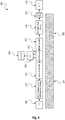
- Fig. 4 is a block diagram of a WiFi transmit chain 400 including synchronizer 312 and fractional delay filter 311 for compensating a time delay difference according to the disclosure.
- the transmit chain 400 includes the same blocks 309, 310, 312, 313, 314, 315, 316 as described above with respect to Fig. 3 for the transmit chain 300. Three additional blocks are added in the transmit chain 400.
- a time-to-digital converter (TDC) 330 is coupled to the synchronizer 312 for measuring the delay of the synchronizer 312.
- a controller 340 is coupled to the TDC 330 to calculate the difference in delay of the synchronizer 312 between sounding packet 111 and data packet 112 (D2-D1) and to configure a fractional delay filter 311 included between the block 310 (adding GI/interpolation chain/PAPR reduction/filtering) and the synchronizer 312.
- the fractional delay filter 311 compensates for D2-D1.
- the fractional delay filter 311 can be implemented by a simple adjustment of integer delay and in other cases it can be incorporated into the existing rate converter 313.
- the fractional delay filter 311 operates at the first clock domain 301.
- the first clock domain 301 may be a digital/modem (lower) clock domain and the second clock domain 302 may be a high-speed DAC (higher) clock domain.
- the synchronizer syncs between these clock domains during active mode.
- the system can go to some power save (or sleep) mode and this is the root of the delay variance problem which is solved by the techniques according to this disclosure.
- the concept according to the disclosure is to measure the delay of the synchronizer 312 during the calibration packet 111 and data packet 112 and to correct the difference on the fly, e.g. by using a dedicated fractional delay filter 311 as described below.
- the delay of the synchronizer 312 during the sounding packet 111 may be denoted as D1.
- the Tx chain 400 is turned-on for the transmission of the data packet 112.
- the delay of the synchronizer 312 measured by TDC 330 may be denoted as D2.
- the fractional delay filter 311 is configured by the controller 340 to compensate for the delay of D2-D1 (in some trivial cases it can be a simple adjustment of integer delay).
- the data packet 112 is transmitted and compensated for D2-D1 by the fractional delay filter 311.
- the random delay of the synchronizer 312 per transmit chain 400 can be compensated.
- these blocks 311, 330, 340 may be active only in beamforming mode.
- the input signal to the synchronizer 312 may be a write clock (which is deterministic) from the modem clock domain 301 and the read clock may come from a different clock domain 302, e.g. DAC 315 driven.
- each transmission read clock may be turned on/off (for power save) and a random delay relative to the write clock may occur. This means that an unpredictable delay may occur in the synchronizer 312 which is also different between the antenna chains.
- the block TDC 330 is added to measure a delay between write and read clocks.
- the novel concept is to measure the random delay of the synchronizer 312 at the beginning of each packet and correct it on the fly, by that eliminating the delay mismatch between Tx chains.
- An alternative to using a fractional delay filter 311 is to apply digital pre-distortion, e.g. by applying a linear phase shift in frequency domain in order to obtain any required time offset.
- the specific filter implemention is less important. It can be implemented in time domain and also in frequency domain. In one implemention time domain implementation can be preferred because an existing implementation of the variable rate converter can be reused.
- the solution provides the highest performance results for high bandwidth signals, e.g. 160MHz and beyond.
- An alternative solution is to keep clocks active for the relevant blocks also during Rx, in this case the delay of the synchronizer 312 will be constant during the sounding packet 111 and the data packet 112. The drawback of this solution would be a high power consumption during Rx which is not desired.
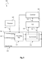
- Fig. 5 is a block diagram of a transmitter device 500 according to the disclosure.
- the transmitter device 500 includes a transmit chain 510 configured to transmit a plurality of transmissions; a processor 520 configured to activate the transmit chain 510 for a first transmission 501, turn off the transmit chain 510 after the first transmission 501 and re-activate the transmit chain 510 for a second transmission 502.
- the transmitter device 500 further includes a synchronizer 512 configured to synchronize the transmit chain 510 upon activation; and a time delay filter 511 coupled to the synchronizer 512.
- the time delay filter 511 is configured to compensate for a time delay difference of the synchronizer 512 upon activation of the transmit chain 510 for the first transmission 501 and activation of the transmit chain 510 for the second transmission 502.
- the time delay filter 511 can delay the transmit signal by an integer or fractional value of the sampling time in order to provide synchronization between the two transmissions 501, 502.
- the transmitter device 500 may further include a time-to-digital converter, TDC 530 configured to determine a time delay of the synchronizer 512.
- the transmitter device 500 may further include a controller 540 configured to determine a first time delay of the synchronizer 512 upon activation of the transmit chain 510 for the first transmission 501 and a second time delay of the synchronizer 512 upon activation of the transmit chain 510 for the second transmission 502.
- the transmitter device 500 is a general representation of the transmitter device 400 described above with respect to Fig. 4 in which the time delay filter 511 may correspond to the fractional delay filter 311, the synchronizer 512 may correspond to the synchronizer 312, the TDC 530 may correspond to the TDC 330 and the controller 540 may correspond to the controller 340.
- controller 540 and processor 520 may be implemented as one functional unit, e.g. as one hardware block.
- the first transmission 501 and the second transmission 502 are not necessarily a sounding packet 111 and a beamforming data packet 112. Both transmissions 501, 502 can specify any two transmissions between which synchronization is lost.
- the controller 540 may be configured to determine a difference of the first time delay and the second time delay; and to adjust the time delay filter 511 based on that difference.
- the time delay filter 511 may include a fractional delay filter, e.g. a fractional delay filter 311 as described above with respect to Fig. 4 .
- the time delay filter 511 may include an integer delay filter for adjustment of integer delay.
- the processor 520 may be configured to activate the transmit chain 510 for transmission of the first transmission 501 and to turn off the transmit chain 510 after transmission of the first transmission 501.
- the processor 520 may be configured to reactivate the transmit chain 510 for transmission of the second transmission 502.
- the transmitter device 500 may include a first clock domain providing a write clock to the synchronizer and a second clock domain providing a read clock to the synchronizer.
- the processor 520 may turn the read clock off after a first transmission and turn the read clock on before a second transmission in order to save power. This results in a random delay relative to the write clock.
- the read clock may be DAC driven and the write clock may be from the modem domain and hence deterministic.
- the controller 540 may determine this random delay between read clock and write clock and provide compensation for this.
- the transmitter device 500 may include a rate converter, e.g. a rate converter 313 as described above with respect to Fig. 4 , configured to convert between the first clock domain and the second clock domain.
- the time delay filter 511 may be included in the rate converter.
- the transmit chain 510 may include a beamforming transmit chain for enabling beamformed transmission.
- the first transmission 501 may include a sounding packet, e.g. a sounding packet 111 as described above with respect to Fig. 2 .
- the second transmission 502 may include a beamformed data packet, e.g. a beamformed data packet 112 as described above with respect to Fig. 2 , which is based on a feedback 222 to the sounding packet 111.
- the processor 520 may be configured to turn off the transmit chain 510 after transmission of the sounding packet 111 until transmission of the beamformed data packet 112.
- the transmit chain 510 may include a WiFi transmit chain.
- the transmitter device 500 may be a beamforming transmitter device 500, including: a transmit chain 510 configured to transmit a plurality of data packets; a processor 520 configured to activate the transmit chain 510 for transmitting a sounding packet 111, turn off the transmit chain 510 after transmission of the sounding packet 111 for reception of a feedback 222 to the sounding packet 111 and re-activate the transmit chain 510 for transmitting a beamformed data packet 112 based on the feedback 222.
- a transmit chain 510 configured to transmit a plurality of data packets
- a processor 520 configured to activate the transmit chain 510 for transmitting a sounding packet 111, turn off the transmit chain 510 after transmission of the sounding packet 111 for reception of a feedback 222 to the sounding packet 111 and re-activate the transmit chain 510 for transmitting a beamformed data packet 112 based on the feedback 222.
- the beamforming transmitter device 500 further includes a synchronizer 512 configured to synchronize the transmit chain 510 when activated; and a time delay filter 511 coupled to the synchronizer 512, wherein the time delay filter 511 is configured to compensate for a time delay difference of the synchronizer 512 upon activation of the transmit chain 510 for transmitting the sounding packet 111 and activation of the transmit chain 510 for transmitting the beamformed data packet 112.
- the beamforming transmitter device 500 may further include a time-to-digital converter 530 configured to determine a time delay of the synchronizer 512.
- the beamforming transmitter device 500 may further include a controller 540 configured to determine a first time delay of the synchronizer 512 upon activation of the transmit chain 510 for transmission of the sounding packet 111 and a second time delay of the synchronizer 512 upon activation of the transmit chain 510 for transmission of the beamformed data packet 112.
- Fig. 6 is a schematic diagram illustrating a method 600 for time delay synchronization according to the disclosure.
- the method 600 includes activating 601 a transmit chain for a first transmission, turning off the transmit chain after the first transmission and re-activating the transmit chain for a second transmission, wherein the transmit chain is synchronized upon activation.
- the transmit chain may be a transmit chain 510 as described above with respect to Fig. 5 or a transmit chain 400 as described above with respect to Fig. 4 .
- the synchronization may be performed by a synchronizer 512 as described above with respect to Fig. 5 or by a synchronizer 312 as described above with respect to Fig. 4 .
- the method 600 further includes compensating 602 for a time delay difference of the synchronization of the transmit chain upon activation for the first transmission and the synchronization of the transmit chain upon activation for the second transmission.
- the compensating 602 may be performed by a time delay filter 511 as described above with respect to Fig. 5 or by a fractional delay filter 311 as described above with respect to Fig. 4 .
- the method 600 may further include: determining a time delay of the synchronization.
- the method 600 may further include: determining a first time delay of the synchronization upon activation of the transmit chain for the first transmission and a second time delay of the synchronization upon activation of the transmit chain for the second transmission.
- the method 600 may further include: determining a difference of the first time delay and the second time delay; and compensating for the time delay difference based on the difference.
- the method 600 may further include: compensating for the time delay difference based on fractional delay filtering, e.g. by a fractional delay filter 311 as described above with respect to Fig. 4 .
- the method 600 may include compensating for the time delay difference based on integer delay filtering.
- the method 600 may further include: activating the transmit chain for transmission of a first transmission and turning off the transmit chain after transmission of the first transmission
- the transmit chain may include a beamforming transmit chain.
- the first transmission may include a sounding packet, e.g. a sounding packet 111 as described above with respect to Fig. 2 .
- the second transmission may include a beamformed data packet which is based on a feedback to the sounding packet, e.g. as described above with respect to Fig. 2 .
- the method 600 may further include turning off the transmit chain after transmission of the sounding packet until reception of the feedback.
- the transmit chain may include a WiFi transmit chain.
- DSP Digital Signal Processors
- ASIC application specific integrated circuit
- Embodiments described in this disclosure can be implemented in digital electronic circuitry, or in computer hardware, firmware, software, or in combinations thereof, e.g. in available hardware of mobile devices or in new hardware dedicated for processing the methods described herein.
- the present disclosure also supports a computer program product including computer executable code or computer executable instructions that, when executed, causes at least one computer to execute the performing and computing blocks described herein, in particular the method 600 described above with respect to Fig. 6 and the techniques described above with respect to Figs. 2 to 5 .
- a computer program product may include a readable storage medium storing program code thereon for use by a processor, the program code comprising instructions for performing the method 600 and the techniques as described above.
- Example 1 is a transmitter device, comprising: a transmit chain configured to transmit a plurality of transmissions; a synchronizer configured to synchronize the transmit chain; and a time delay filter coupled to the synchronizer, wherein the time delay filter is configured to compensate for a time delay difference of the synchronizer.
- Example 2 the subject matter of Example 1 can optionally include a time-to-digital converter configured to determine a time delay of the synchronizer.
- Example 3 the subject matter of Example 2 can optionally include a controller configured to determine a first time delay of the synchronizer for a first transmission and a second time delay of the synchronizer for a second transmission.
- Example 4 the subject matter of Example 3 can optionally include that the controller is configured to determine a difference of the first time delay and the second time delay; and to adjust the time delay filter based on the difference.
- Example 5 the subject matter of any one of Examples 1-4 can optionally include that the time delay filter comprises a fractional delay filter.
- Example 6 the subject matter of any one of Examples 1-5 can optionally include that the time delay filter comprises an integer delay filter for adjustment of integer delay.
- Example 7 the subject matter of any one of Examples 1-6 can optionally include a first clock domain configured to provide a write clock to the synchronizer; and a second clock domain configured to provide a read clock to the synchronizer.
- Example 8 the subject matter of Example 7 can optionally include a rate converter configured to convert between the first clock domain and the second clock domain.
- Example 9 the subject matter of Example 8 can optionally include that the time delay filter is comprised in the rate converter and configured to determine a delay between the read clock and the write clock.
- Example 10 the subject matter of any one of Examples 1-9 can optionally include that the transmit chain comprises a beamforming transmit chain.
- Example 11 the subject matter of Example 10 can optionally include that the first transmission comprises a sounding packet.
- Example 12 the subject matter of Example 11 can optionally include that the second transmission comprises a beamformed data packet which is based on a feedback to the sounding packet.
- Example 13 the subject matter of Example 7 can optionally include a processor configured to turn off the read clock after a first transmission and to turn on the read clock before a second transmission in order to save power.
- Example 14 the subject matter of any one of Examples 1-13 can optionally include that the transmit chain comprises a WiFi transmit chain.
- Example 15 is a beamforming transmitter device, comprising: a transmit chain configured to transmit a plurality of data packets; a processor configured to activate the transmit chain for transmitting a sounding packet, turn off the transmit chain after transmission of the sounding packet for reception of a feedback to the sounding packet and re-activate the transmit chain for transmitting a beamformed data packet based on the feedback; a synchronizer configured to synchronize the transmit chain when activated; and a time delay filter coupled to the synchronizer, wherein the time delay filter is configured to compensate for a time delay difference of the synchronizer upon activation of the transmit chain for transmitting the sounding packet and activation of the transmit chain for transmitting the beamformed data packet.
- Example 16 the subject matter of Example 15 can optionally include a time-to-digital converter configured to determine a time delay of the synchronizer.
- Example 17 the subject matter of Example 16 can optionally include a controller configured to determine a first time delay of the synchronizer upon activation of the transmit chain for transmission of the sounding packet and a second time delay of the synchronizer upon activation of the transmit chain for transmission of the beamformed data packet.
- Example 18 the subject matter of Example 17 can optionally include that the controller is configured to determine a difference of the first time delay and the second time delay; and to adjust the time delay filter based on the difference.
- Example 19 the subject matter of any one of Examples 15-18 can optionally include that the time delay filter comprises a fractional delay filter.
- Example 20 the subject matter of any one of Examples 15-19 can optionally include that the time delay filter comprises an integer delay filter for adjustment of integer delay.
- Example 21 the subject matter of any one of Examples 15-20 can optionally include that the processor is configured to activate the transmit chain based on switching the transmit chain to a first clock domain and to turn off the transmit chain based on switching the transmit chain to a second clock domain.
- Example 22 the subject matter of Example 21 can optionally include a rate converter configured to convert between the first clock domain and the second clock domain.
- Example 23 the subject matter of Example 22 can optionally include that the time delay filter is comprised in the rate converter.
- Example 24 the subject matter of any one of Examples 15-23 can optionally include that the transmit chain comprises a WiFi transmit chain.
- Example 25 is a method for time delay synchronization, the method comprising: activating a transmit chain for a first transmission, turning off the transmit chain after the first transmission and re-activating the transmit chain for a second transmission, wherein the transmit chain is synchronized upon activation; and compensating for a time delay difference of the synchronization of the transmit chain upon activation for the first transmission and the synchronization of the transmit chain upon activation for the second transmission.
- Example 26 the subject matter of Example 25 can optionally include determining a time delay of the synchronization.
- Example 27 the subject matter of Example 26 can optionally include: determining a first time delay of the synchronization upon activation of the transmit chain for the first transmission and a second time delay of the synchronization upon activation of the transmit chain for the second transmission.
- Example 28 the subject matter of Example 27 can optionally include: determining a difference of the first time delay and the second time delay; and compensating for the time delay difference based on the difference.
- Example 29 the subject matter of any one of Examples 25-28 can optionally include: compensating for the time delay difference based on fractional delay filtering.
- Example 30 the subject matter of any one of Examples 25-29 can optionally include: compensating for the time delay difference based on integer delay filtering.
- Example 31 the subject matter of any one of Examples 25-30 can optionally include: activating the transmit chain based on switching the transmit chain to a first clock domain and turning off the transmit chain based on switching the transmit chain to a second clock domain.
- Example 32 the subject matter of Example 31 can optionally include: converting between the first clock domain and the second clock domain based on a rate converter.
- Example 33 the subject matter of any one of Examples 25-32 can optionally include that the transmit chain comprises a beamforming transmit chain.
- Example 34 the subject matter of Example 33 can optionally include that the first transmission comprises a sounding packet.
- Example 35 the subject matter of Example 34 can optionally include that the second transmission comprises a beamformed data packet which is based on a feedback to the sounding packet.
- Example 36 the subject matter of Example 35 can optionally include: turning off the transmit chain after transmission of the sounding packet until reception of the feedback.
- Example 37 the subject matter of any one of Examples 25-36 can optionally include that the transmit chain comprises a WiFi transmit chain.
- Example 38 is a device for time delay synchronization, the device comprising: means for activating a transmit chain for a first transmission, turning off the transmit chain after the first transmission and re-activating the transmit chain for a second transmission, wherein the transmit chain is synchronized upon activation; and means for compensating for a time delay difference of the synchronization of the transmit chain upon activation for the first transmission and the synchronization of the transmit chain upon activation for the second transmission.
- Example 39 the subject matter of Example 38 can optionally include means for determining a time delay of the synchronization.
- Example 40 is a beamforming system, comprising a transmit device and a receive device, wherein the transmit device comprises: a transmit chain configured to transmit a plurality of data packets; a processor configured to activate the transmit chain for transmitting a sounding packet, turn off the transmit chain after transmission of the sounding packet for reception of a feedback to the sounding packet and re-activate the transmit chain for transmitting a beamformed data packet based on the feedback; a synchronizer configured to synchronize the transmit chain when activated; and a time delay filter coupled to the synchronizer, wherein the time delay filter is configured to compensate for a time delay difference of the synchronizer upon activation of the transmit chain for transmitting the sounding packet and activation of the transmit chain for transmitting the beamformed data packet, wherein the receive device comprises: a receiver configured to receive the sounding packet; and a transmit chain configured to transmit the feedback to the sounding packet.
- Example 41 the subject matter of Example 40 can optionally include that the transmit device comprises a time-to-digital converter configured to determine a time delay of the synchronizer.
- Example 42 is a beamforming transmitter circuit, comprising: a transmit chain configured to transmit a plurality of data packets; a processor configured to activate the transmit chain for transmitting a sounding packet, turn off the transmit chain after transmission of the sounding packet for reception of a feedback to the sounding packet and re-activate the transmit chain for transmitting a beamformed data packet based on the feedback; a synchronizer circuit configured to synchronize the transmit chain when activated; and a time delay filter circuit coupled to the synchronizer circuit, wherein the time delay filter circuit is configured to compensate for a time delay difference of the synchronizer circuit upon activation of the transmit chain for transmitting the sounding packet and activation of the transmit chain for transmitting the beamformed data packet.
- Example 43 the subject matter of Example 42 can optionally include: a time-to-digital converter circuit configured to determine a time delay of the synchronizer circuit.
- Example 44 the subject matter of Example 43 can optionally include: a controller configured to determine a first time delay of the synchronizer circuit upon activation of the transmit chain for transmission of the sounding packet and a second time delay of the synchronizer circuit upon activation of the transmit chain for transmission of the beamformed data packet.
- Example 45 is a computer readable non-transitory medium on which computer instructions are stored which when executed by a computer cause the computer to perform the method of any one of Examples 25 to 37.
Landscapes
- Engineering & Computer Science (AREA)
- Computer Networks & Wireless Communication (AREA)
- Signal Processing (AREA)
- Radio Transmission System (AREA)
Abstract
Description
- The disclosure relates to a transmitter device and a beamforming transmitter device with time delay filter compensating for a time delay difference resulting from synchronizing. In particular, the disclosure relates to time delay synchronization of multiple transmit chains for multiple-input multiple-output (MIMO) communication in the scenario of transmit (Tx) Beamforming for Time Division Duplexing (TDD) deployment.
-
Figure 1 shows amobile communication device 100 for MIMO communication in the scenario of Tx beamforming with a transmit chain for beamforming sounding 101 that transmits a soundingpacket 111 and a transmit chain forbeamforming data packets 103 that transmitsdata packets 112. Due to synchronization of thechains delay variance 113 between thechains chain - The accompanying drawings are included to provide a further understanding of embodiments and are incorporated in and constitute a part of this specification. The drawings illustrate embodiments and together with the description serve to explain principles of embodiments. Other embodiments and many of the intended advantages of embodiments will be readily appreciated as they become better understood by reference to the following detailed description.
-
Fig. 1 is a schematic diagram of amobile communication device 100 with delay variance between transmit chains for beamforming sounding and beamforming data packets. -
Fig. 2 is a schematic diagram illustrating abeamforming flow 200 between twocommunication devices -
Fig. 3 is a block diagram of aWiFi transmit chain 300 operating at twoclock domains synchronizer 312 in between. -
Fig. 4 is a block diagram of aWiFi transmit chain 400 includingsynchronizer 312 andfractional delay filter 311 for compensating a time delay difference according to the disclosure. -
Fig. 5 is a block diagram of atransmitter device 500 according to the disclosure. -
Fig. 6 is a schematic diagram illustrating amethod 600 for time delay synchronization according to the disclosure. - In the following detailed description, reference is made to the accompanying drawings, which form a part thereof, and in which is shown by way of illustration specific aspects in which the invention may be practiced. It is understood that other aspects may be utilized and structural or logical changes may be made without departing from the scope of the present invention. The following detailed description, therefore, is not to be taken in a limiting sense, and the scope of the present invention is defined by the appended claims.
- The following terms, abbreviations and notations will be used herein:
- MIMO: Multiple Input Multiple Output
- BF: Beamforming
- RF: Radio Frequency
- LTE: Long Term Evolution
- UE: User Equipment, mobile device, mobile terminal
- OFDM: Orthogonal Frequency Division Multiplex eNB,
- eNodeB: Base station
- TDD: Time Division Duplexing
- Tx: Transmit, Transmitter
- Rx: Receive, Receiver
- FFT: Fast Fourier Transform
- GI: Guard Interval
- PAPR: Peak to average power ratio
- HS DAC: High-speed digital-to-analog converter
- RFIC: Radio Frequency Integrated Circuit
- TDC: Time-to-Digital Converter
- BW: Bandwidth
- MCS: Modulation and Coding Set
- The methods and devices described herein may be applied in mobile communication devices, mobile terminals, mobile stations and user equipments (UEs). It is understood that comments made in connection with a described method may also hold true for a corresponding device configured to perform the method and vice versa. For example, if a specific method step is described, a corresponding device may include a unit to perform the described method step, even if such a unit is not explicitly described or illustrated in the figures. Further, it is understood that the features of the various exemplary aspects described herein may be combined with each other, unless specifically noted otherwise.
- The methods and devices described herein may be implemented in wireless communication networks, in particular communication networks based on connectivity standards, in particular high speed standards from the 802.11 family e.g. 802.11ad and successor standards. The methods are also applicable for mobile communication standards such as LTE, in particular LTE-A and/or OFDM and successor standards such as 5G. The methods and devices described below may be implemented in electronic devices, in particular electronic circuits of mobile communication devices, mobile terminals, stations and UEs. The described devices may include integrated circuits and/or passives and may be manufactured according to various technologies. For example, the circuits may be designed as logic integrated circuits, analog integrated circuits, mixed signal integrated circuits, optical circuits, memory circuits and/or integrated passives.
- Methods and devices described in this disclosure may be based on beamforming, in particular Tx beamforming. Beamforming also referred to as spatial filtering is a signal processing technique used in sensor arrays and antenna arrays for directional signal transmission or reception. This is achieved by combining elements in a phased array in such a way that signals at particular angles experience constructive interference while others experience destructive interference. Beamforming can be used at both the transmitting and receiving ends in order to achieve spatial selectivity. The improvement compared with omnidirectional reception/transmission is known as the directivity of the element. The 802.11n standard defines a few methods of beamforming. One method, referred to as "explicit" beamforming, requires the downstream channel to be measured at the receiver, or beamformee, and relayed back to the transmitter, or beamformer. The beamformer uses the measured channel information to derive the transmit beamforming parameters.
- Methods and devices described in this disclosure tackle the problem of time delay synchronization of multiple transmit chains (MIMO) in the scenario of Tx Beamforming for TDD deployment. Adaptive transmit beamforming is highly adopted by many standards including 802.11n, 802.11ac and 802.11ax. In methods and devices according to this disclosure transmit beamforming (TxBF) weights are applied to the transmitted signal to improve reception. The weights are adapted from knowledge of the propagation environment or channel state information (CSI). The key advantage with transmit beamforming is the ability to significantly improving link performance to a low cost, low complexity device. Tx transmit beamforming can also be used for MU-MIMO in order to increase the cell capacity. Transmit beamforming can be applied to each subcarrier in the frequency band.
- Methods and devices described in this disclosure can be applied in Time-division duplexing (TDD) communication systems. TDD is the application of time-division multiplexing to separate outward and return signals. It emulates full duplex communication over a half-duplex communication link. Time-division duplexing has a strong advantage in the case where there is asymmetry of the uplink and downlink data rates. As the amount of uplink data increases, more communication capacity can be dynamically allocated, and as the traffic load becomes lighter, capacity can be taken away. The same applies in the downlink direction. For radio systems that are not moving quickly, another advantage is that the uplink and downlink radio paths are likely to be very similar. This means that techniques such as beamforming work well with TDD systems.
- Methods and devices described in this disclosure may apply fractional delay filters and fractional delay filtering. A fractional delay filter is a digital filter which main function is to delay a processed input signal for a fractional of the sampling period time. There are two main design approaches in fractional delay filtering which are time-domain and frequency-domain design methods. In the time-domain design, the fractional delay filter coefficients are obtained by mathematical interpolation formulas, but there is a small flexibility to meet frequency-domain specifications. In contrast, frequency-domain design methods are based on frequency optimization, and a more frequency specification control is available. Frequency-domain methods have a highly efficient implementation structure, which allows online fractional value update.
- Methods and devices described in this disclosure may apply time-to-digital converters (TDCs). Time-to-digital converters (TDCs), also referred to as time digitizers are devices that are used to measure a time interval and to convert it into a digital (e.g. binary) output. TDCs are used, for example, in applications, where the time interval between two signal pulses (e.g. a start pulse and a stop pulse) shall be determined. Measurement is started and stopped, when either of the rising or the falling edge of a signal pulse crosses a predetermined threshold.
- The methods and devices described herein may be configured to transmit and/or receive radio signals and performing associated signal processing. Radio signals may be or may include radio frequency signals radiated by a radio transmitting device (or radio transmitter or sender) with a radio frequency lying in a range of about 3 kHz to 300 GHz. The frequency range may correspond to frequencies of alternating current electrical signals used to produce and detect radio waves.
- The methods and devices described hereinafter may be applied in OFDM systems. OFDM is a scheme for encoding digital data on multiple carrier frequencies. A large number of closely spaced orthogonal sub-carrier signals may be used to carry data. Due to the orthogonality of the sub-carriers crosstalk between sub-carriers may be suppressed.
- The methods and devices described hereinafter may be applied in MIMO systems, in particular multiuser MIMO systems and diversity receivers. Multiple-input multiple-output (MIMO) wireless communication systems employ multiple antennas at the transmitter and/or at the receiver to increase system capacity and to achieve better quality of service. In spatial multiplexing mode, MIMO systems may reach higher peak data rates without increasing the bandwidth of the system by transmitting multiple data streams in parallel in the same frequency band. A diversity receiver uses two or more antennas to improve the quality and reliability of a wireless link.
- In the following, embodiments are described with reference to the drawings, wherein like reference numerals are generally utilized to refer to like elements throughout. In the following description, for purposes of explanation, numerous specific details are set forth in order to provide a thorough understanding of one or more aspects of embodiments. However, it may be evident to a person skilled in the art that one or more aspects of the embodiments may be practiced with a lesser degree of these specific details. The following description is therefore not to be taken in a limiting sense.
- The various aspects summarized may be embodied in various forms. The following description shows by way of illustration various combinations and configurations in which the aspects may be practiced. It is understood that the described aspects and/or embodiments are merely examples, and that other aspects and/or embodiments may be utilized and structural and functional modifications may be made without departing from the scope of the present disclosure.
-
Fig. 2 is a schematic diagram illustrating abeamforming flow 200 between twocommunication devices - In order to determine the weights for
Tx beamforming 213, knowledge of the CSI is required. Thedevice 210 performingTx BF 213 is thesame device 210 that transmits the soundingpacket 111. Device A, 210 sends a soundingpacket 111 to device B, 220. Device B, 220 transmits the CSI or beamforming weights asfeedback 222 to device A, 210. Device A, 210 uses thefeedback 222 to transmit apacket 112 withTx BF 213 to device B, 220. Ideally, the channel remains the same between thetime 230 the soundingpacket 111 is sent and thetime 230 thebeamformed packet 112 is sent. - In devices according to the disclosure as described in the following, the time delay variation between transmit chains for sending the sounding
packet 111 and sending thebeamformed packet 112 is compensated, i.e. the different delay inside the synchronizer (which implies different total delay of each chain) in packet A (sounding) relative to packet B (beamforming) is compensated. -
Fig. 3 is a block diagram of a WiFi transmitchain 300 operating at twoclock domains synchronizer 312 in between. The transmitchain 300 includes the followingblocks second block 310 adds a guard interval (GI) to the transmit signal, applies an interpolation chain, performs peak-to-average power reduction (PAPR) and filtering. The first twoblocks blocks third block 312 is a synchronizer for synchronizing the WiFi transmitchain 300 between operation at thefirst clock domain 301 and operation at thesecond clock domain 302. Afourth block 313 is a rate converter to convert the rate of the transmit signal synchronized by thesynchronizer 312 from a first rate to a second rate. Afifth block 314 is an interpolation chain and filtering block for interpolating and filtering the rate-converted transmit signal which is then output to a high-speed digital-to-analog converter (DAC) 315 and forwarded to a radio frequency integrated circuit (RFIC) for transmission over a radio channel. - In order to benefit from the beamforming gain, the time delay between multiple transmit chains for sounding
packet 111 and data packet 112 (as described above with respect toFigures 1 and2 ) should be the same. This is not happening in the WiFi Tx chain. In a WiFi device, theTx chain 300 is active during transmit and disabled (including clocks for power save) during receive. - The WiFi transmit
chain 300 includesdifferent clock domains synchronizers 312 between them. The delay of thesynchronizer 312 is random up to +/-1 Tclock per activation. Since delay of every chain is random up to the uncertainty of thesynchronizer 312, the delay between Tx chains is random between activations. Not constant time delay between multiple transmit chains during soundingpacket 111 anddata packet 112 will significantly degrade beamforming gain. - If the timing offset between
different Tx chains 300 is different between soundingpacket 111 anddata packet 112 by 2/BW it will lead to destructive interference between high frequency tones. For example for BW=160MHz, when the timing offset is reaching 12.5ns (2/160MHz) such distractive interference will occur. In order to enjoy maximal possible gain, the time delay change should be below 1ns. This is a very tough requirement. - The concept according to the disclosure is to measure the delay of Transmit
chain 300 and correct it on the fly, in order to obtain full beamforming gain of high BW signals. This approach enables to obtain full beamforming gain for high BW signals. - The delay of synchronizer can be measured during the calibration packet, i.e. the sounding packet, and the data packet and the difference can be corrected on the fly, e.g. by using a dedicated fractional delay filter.
- In the following example, the new flow can be described as follows: 1. Measure delay of
synchronizer 312 during soundingpacket 111, e.g. denoted by D1. 2. Turn onTx chain 300 for the transmission ofdata packet 112. 3. Measure the delay ofsynchronizer 312, e.g. denoted by D2. 4. Configure a fractional delay filter, e.g.fractional delay filter 311 as depicted inFig. 4 , to compensate delay of D2-D1 (in some trivial cases it can be simple adjustment of integer delay). 5. Transmitdata packet 112. Note that in this example compensation is for the random delay ofsynchronizer 312 per transmitchain 300. It is enough to compensate only the difference of time delay between multiple Tx chains, e.g.multiple Tx chains 300 as depicted inFig. 3 . -
Fig. 4 is a block diagram of a WiFi transmitchain 400 includingsynchronizer 312 andfractional delay filter 311 for compensating a time delay difference according to the disclosure. - The transmit
chain 400 includes thesame blocks Fig. 3 for the transmitchain 300. Three additional blocks are added in the transmitchain 400. A time-to-digital converter (TDC) 330 is coupled to thesynchronizer 312 for measuring the delay of thesynchronizer 312. Acontroller 340 is coupled to theTDC 330 to calculate the difference in delay of thesynchronizer 312 between soundingpacket 111 and data packet 112 (D2-D1) and to configure afractional delay filter 311 included between the block 310 (adding GI/interpolation chain/PAPR reduction/filtering) and thesynchronizer 312. Thefractional delay filter 311 compensates for D2-D1. In some cases thefractional delay filter 311 can be implemented by a simple adjustment of integer delay and in other cases it can be incorporated into the existingrate converter 313. Thefractional delay filter 311 operates at thefirst clock domain 301. - The
first clock domain 301 may be a digital/modem (lower) clock domain and thesecond clock domain 302 may be a high-speed DAC (higher) clock domain. The synchronizer syncs between these clock domains during active mode. The system can go to some power save (or sleep) mode and this is the root of the delay variance problem which is solved by the techniques according to this disclosure. - As described above with respect to
Fig. 3 , the concept according to the disclosure is to measure the delay of thesynchronizer 312 during thecalibration packet 111 anddata packet 112 and to correct the difference on the fly, e.g. by using a dedicatedfractional delay filter 311 as described below. The delay of thesynchronizer 312 during the soundingpacket 111 may be denoted as D1. Then theTx chain 400 is turned-on for the transmission of thedata packet 112. The delay of thesynchronizer 312 measured byTDC 330 may be denoted as D2. Then thefractional delay filter 311 is configured by thecontroller 340 to compensate for the delay of D2-D1 (in some trivial cases it can be a simple adjustment of integer delay). Thedata packet 112 is transmitted and compensated for D2-D1 by thefractional delay filter 311. In this example the random delay of the synchronizer 312 per transmitchain 400 can be compensated. In one implementation it may be enough to compensate only the difference of time delay between multiple Tx chains. In one implementation, theseblocks - The concept described above solves a new problem that arises for example in high BW (WiFi BW = 160MHz/5G BW = 200MHz and etc..), high MCS (256QAM,1024QAM), multiple antennas Tx beamforming scenarios.
- In one implementation, the input signal to the
synchronizer 312 may be a write clock (which is deterministic) from themodem clock domain 301 and the read clock may come from adifferent clock domain 302, e.g.DAC 315 driven. In each transmission read clock may be turned on/off (for power save) and a random delay relative to the write clock may occur. This means that an unpredictable delay may occur in thesynchronizer 312 which is also different between the antenna chains. Theblock TDC 330 is added to measure a delay between write and read clocks. - The novel concept is to measure the random delay of the
synchronizer 312 at the beginning of each packet and correct it on the fly, by that eliminating the delay mismatch between Tx chains. An alternative to using afractional delay filter 311 is to apply digital pre-distortion, e.g. by applying a linear phase shift in frequency domain in order to obtain any required time offset. However, the specific filter implemention is less important. It can be implemented in time domain and also in frequency domain. In one implemention time domain implementation can be preferred because an existing implementation of the variable rate converter can be reused. - The solution provides the highest performance results for high bandwidth signals, e.g. 160MHz and beyond. An alternative solution is to keep clocks active for the relevant blocks also during Rx, in this case the delay of the
synchronizer 312 will be constant during the soundingpacket 111 and thedata packet 112. The drawback of this solution would be a high power consumption during Rx which is not desired. -
Fig. 5 is a block diagram of atransmitter device 500 according to the disclosure. Thetransmitter device 500 includes a transmitchain 510 configured to transmit a plurality of transmissions; aprocessor 520 configured to activate the transmitchain 510 for afirst transmission 501, turn off the transmitchain 510 after thefirst transmission 501 and re-activate the transmitchain 510 for asecond transmission 502. Thetransmitter device 500 further includes asynchronizer 512 configured to synchronize the transmitchain 510 upon activation; and atime delay filter 511 coupled to thesynchronizer 512. Thetime delay filter 511 is configured to compensate for a time delay difference of thesynchronizer 512 upon activation of the transmitchain 510 for thefirst transmission 501 and activation of the transmitchain 510 for thesecond transmission 502. Thetime delay filter 511 can delay the transmit signal by an integer or fractional value of the sampling time in order to provide synchronization between the twotransmissions - The
transmitter device 500 may further include a time-to-digital converter,TDC 530 configured to determine a time delay of thesynchronizer 512. Thetransmitter device 500 may further include acontroller 540 configured to determine a first time delay of thesynchronizer 512 upon activation of the transmitchain 510 for thefirst transmission 501 and a second time delay of thesynchronizer 512 upon activation of the transmitchain 510 for thesecond transmission 502. - The
transmitter device 500 is a general representation of thetransmitter device 400 described above with respect toFig. 4 in which thetime delay filter 511 may correspond to thefractional delay filter 311, thesynchronizer 512 may correspond to thesynchronizer 312, theTDC 530 may correspond to theTDC 330 and thecontroller 540 may correspond to thecontroller 340. In oneimplementation controller 540 andprocessor 520 may be implemented as one functional unit, e.g. as one hardware block. For thetransmitter device 500, thefirst transmission 501 and thesecond transmission 502 are not necessarily a soundingpacket 111 and abeamforming data packet 112. Bothtransmissions - The
controller 540 may be configured to determine a difference of the first time delay and the second time delay; and to adjust thetime delay filter 511 based on that difference. Thetime delay filter 511 may include a fractional delay filter, e.g. afractional delay filter 311 as described above with respect toFig. 4 . Thetime delay filter 511 may include an integer delay filter for adjustment of integer delay. - The
processor 520 may be configured to activate the transmitchain 510 for transmission of thefirst transmission 501 and to turn off the transmitchain 510 after transmission of thefirst transmission 501. Theprocessor 520 may be configured to reactivate the transmitchain 510 for transmission of thesecond transmission 502. Thetransmitter device 500 may include a first clock domain providing a write clock to the synchronizer and a second clock domain providing a read clock to the synchronizer. Theprocessor 520 may turn the read clock off after a first transmission and turn the read clock on before a second transmission in order to save power. This results in a random delay relative to the write clock. The read clock may be DAC driven and the write clock may be from the modem domain and hence deterministic. Thecontroller 540 may determine this random delay between read clock and write clock and provide compensation for this. - The
transmitter device 500 may include a rate converter, e.g. arate converter 313 as described above with respect toFig. 4 , configured to convert between the first clock domain and the second clock domain. Thetime delay filter 511 may be included in the rate converter. - The transmit
chain 510 may include a beamforming transmit chain for enabling beamformed transmission. Thefirst transmission 501 may include a sounding packet, e.g. a soundingpacket 111 as described above with respect toFig. 2 . Thesecond transmission 502 may include a beamformed data packet, e.g. abeamformed data packet 112 as described above with respect toFig. 2 , which is based on afeedback 222 to the soundingpacket 111. - The
processor 520 may be configured to turn off the transmitchain 510 after transmission of the soundingpacket 111 until transmission of thebeamformed data packet 112. In one implementation, the transmitchain 510 may include a WiFi transmit chain. - In one example, the
transmitter device 500 may be abeamforming transmitter device 500, including: a transmitchain 510 configured to transmit a plurality of data packets; aprocessor 520 configured to activate the transmitchain 510 for transmitting a soundingpacket 111, turn off the transmitchain 510 after transmission of the soundingpacket 111 for reception of afeedback 222 to the soundingpacket 111 and re-activate the transmitchain 510 for transmitting abeamformed data packet 112 based on thefeedback 222. Thebeamforming transmitter device 500 further includes asynchronizer 512 configured to synchronize the transmitchain 510 when activated; and atime delay filter 511 coupled to thesynchronizer 512, wherein thetime delay filter 511 is configured to compensate for a time delay difference of thesynchronizer 512 upon activation of the transmitchain 510 for transmitting the soundingpacket 111 and activation of the transmitchain 510 for transmitting thebeamformed data packet 112. - The
beamforming transmitter device 500 may further include a time-to-digital converter 530 configured to determine a time delay of thesynchronizer 512. Thebeamforming transmitter device 500 may further include acontroller 540 configured to determine a first time delay of thesynchronizer 512 upon activation of the transmitchain 510 for transmission of the soundingpacket 111 and a second time delay of thesynchronizer 512 upon activation of the transmitchain 510 for transmission of thebeamformed data packet 112. -
Fig. 6 is a schematic diagram illustrating amethod 600 for time delay synchronization according to the disclosure. - The
method 600 includes activating 601 a transmit chain for a first transmission, turning off the transmit chain after the first transmission and re-activating the transmit chain for a second transmission, wherein the transmit chain is synchronized upon activation. The transmit chain may be a transmitchain 510 as described above with respect toFig. 5 or a transmitchain 400 as described above with respect toFig. 4 . The synchronization may be performed by asynchronizer 512 as described above with respect toFig. 5 or by asynchronizer 312 as described above with respect toFig. 4 . Themethod 600 further includes compensating 602 for a time delay difference of the synchronization of the transmit chain upon activation for the first transmission and the synchronization of the transmit chain upon activation for the second transmission. The compensating 602 may be performed by atime delay filter 511 as described above with respect toFig. 5 or by afractional delay filter 311 as described above with respect toFig. 4 . - The
method 600 may further include: determining a time delay of the synchronization. Themethod 600 may further include: determining a first time delay of the synchronization upon activation of the transmit chain for the first transmission and a second time delay of the synchronization upon activation of the transmit chain for the second transmission. - The
method 600 may further include: determining a difference of the first time delay and the second time delay; and compensating for the time delay difference based on the difference. Themethod 600 may further include: compensating for the time delay difference based on fractional delay filtering, e.g. by afractional delay filter 311 as described above with respect toFig. 4 . Alternatively, themethod 600 may include compensating for the time delay difference based on integer delay filtering. - The
method 600 may further include: activating the transmit chain for transmission of a first transmission and turning off the transmit chain after transmission of the first transmission - The transmit chain may include a beamforming transmit chain. The first transmission may include a sounding packet, e.g. a sounding
packet 111 as described above with respect toFig. 2 . The second transmission may include a beamformed data packet which is based on a feedback to the sounding packet, e.g. as described above with respect toFig. 2 . Themethod 600 may further include turning off the transmit chain after transmission of the sounding packet until reception of the feedback. The transmit chain may include a WiFi transmit chain. - The devices and systems described in this disclosure may be implemented as Digital Signal Processors (DSP), microcontrollers or any other side-processor or hardware circuit on a chip or an application specific integrated circuit (ASIC).
- Embodiments described in this disclosure can be implemented in digital electronic circuitry, or in computer hardware, firmware, software, or in combinations thereof, e.g. in available hardware of mobile devices or in new hardware dedicated for processing the methods described herein.
- The present disclosure also supports a computer program product including computer executable code or computer executable instructions that, when executed, causes at least one computer to execute the performing and computing blocks described herein, in particular the
method 600 described above with respect toFig. 6 and the techniques described above with respect toFigs. 2 to 5 . Such a computer program product may include a readable storage medium storing program code thereon for use by a processor, the program code comprising instructions for performing themethod 600 and the techniques as described above. - The following examples pertain to further embodiments. Example 1 is a transmitter device, comprising: a transmit chain configured to transmit a plurality of transmissions; a synchronizer configured to synchronize the transmit chain; and a time delay filter coupled to the synchronizer, wherein the time delay filter is configured to compensate for a time delay difference of the synchronizer.
- In Example 2, the subject matter of Example 1 can optionally include a time-to-digital converter configured to determine a time delay of the synchronizer.
- In Example 3, the subject matter of Example 2 can optionally include a controller configured to determine a first time delay of the synchronizer for a first transmission and a second time delay of the synchronizer for a second transmission.
- In Example 4, the subject matter of Example 3 can optionally include that the controller is configured to determine a difference of the first time delay and the second time delay; and to adjust the time delay filter based on the difference.
- In Example 5, the subject matter of any one of Examples 1-4 can optionally include that the time delay filter comprises a fractional delay filter.
- In Example 6, the subject matter of any one of Examples 1-5 can optionally include that the time delay filter comprises an integer delay filter for adjustment of integer delay.
- In Example 7, the subject matter of any one of Examples 1-6 can optionally include a first clock domain configured to provide a write clock to the synchronizer; and a second clock domain configured to provide a read clock to the synchronizer.
- In Example 8, the subject matter of Example 7 can optionally include a rate converter configured to convert between the first clock domain and the second clock domain.
- In Example 9, the subject matter of Example 8 can optionally include that the time delay filter is comprised in the rate converter and configured to determine a delay between the read clock and the write clock.
- In Example 10, the subject matter of any one of Examples 1-9 can optionally include that the transmit chain comprises a beamforming transmit chain.
- In Example 11, the subject matter of Example 10 can optionally include that the first transmission comprises a sounding packet.
- In Example 12, the subject matter of Example 11 can optionally include that the second transmission comprises a beamformed data packet which is based on a feedback to the sounding packet.
- In Example 13, the subject matter of Example 7 can optionally include a processor configured to turn off the read clock after a first transmission and to turn on the read clock before a second transmission in order to save power.
- In Example 14, the subject matter of any one of Examples 1-13 can optionally include that the transmit chain comprises a WiFi transmit chain.
- Example 15 is a beamforming transmitter device, comprising: a transmit chain configured to transmit a plurality of data packets; a processor configured to activate the transmit chain for transmitting a sounding packet, turn off the transmit chain after transmission of the sounding packet for reception of a feedback to the sounding packet and re-activate the transmit chain for transmitting a beamformed data packet based on the feedback; a synchronizer configured to synchronize the transmit chain when activated; and a time delay filter coupled to the synchronizer, wherein the time delay filter is configured to compensate for a time delay difference of the synchronizer upon activation of the transmit chain for transmitting the sounding packet and activation of the transmit chain for transmitting the beamformed data packet.
- In Example 16, the subject matter of Example 15 can optionally include a time-to-digital converter configured to determine a time delay of the synchronizer.
- In Example 17, the subject matter of Example 16 can optionally include a controller configured to determine a first time delay of the synchronizer upon activation of the transmit chain for transmission of the sounding packet and a second time delay of the synchronizer upon activation of the transmit chain for transmission of the beamformed data packet.
- In Example 18, the subject matter of Example 17 can optionally include that the controller is configured to determine a difference of the first time delay and the second time delay; and to adjust the time delay filter based on the difference.
- In Example 19, the subject matter of any one of Examples 15-18 can optionally include that the time delay filter comprises a fractional delay filter.
- In Example 20, the subject matter of any one of Examples 15-19 can optionally include that the time delay filter comprises an integer delay filter for adjustment of integer delay.
- In Example 21, the subject matter of any one of Examples 15-20 can optionally include that the processor is configured to activate the transmit chain based on switching the transmit chain to a first clock domain and to turn off the transmit chain based on switching the transmit chain to a second clock domain.
- In Example 22, the subject matter of Example 21 can optionally include a rate converter configured to convert between the first clock domain and the second clock domain.
- In Example 23, the subject matter of Example 22 can optionally include that the time delay filter is comprised in the rate converter.
- In Example 24, the subject matter of any one of Examples 15-23 can optionally include that the transmit chain comprises a WiFi transmit chain.
- Example 25 is a method for time delay synchronization, the method comprising: activating a transmit chain for a first transmission, turning off the transmit chain after the first transmission and re-activating the transmit chain for a second transmission, wherein the transmit chain is synchronized upon activation; and compensating for a time delay difference of the synchronization of the transmit chain upon activation for the first transmission and the synchronization of the transmit chain upon activation for the second transmission.
- In Example 26, the subject matter of Example 25 can optionally include determining a time delay of the synchronization.
- In Example 27, the subject matter of Example 26 can optionally include: determining a first time delay of the synchronization upon activation of the transmit chain for the first transmission and a second time delay of the synchronization upon activation of the transmit chain for the second transmission.
- In Example 28, the subject matter of Example 27 can optionally include: determining a difference of the first time delay and the second time delay; and compensating for the time delay difference based on the difference.
- In Example 29, the subject matter of any one of Examples 25-28 can optionally include: compensating for the time delay difference based on fractional delay filtering.
- In Example 30, the subject matter of any one of Examples 25-29 can optionally include: compensating for the time delay difference based on integer delay filtering.
- In Example 31, the subject matter of any one of Examples 25-30 can optionally include: activating the transmit chain based on switching the transmit chain to a first clock domain and turning off the transmit chain based on switching the transmit chain to a second clock domain.
- In Example 32, the subject matter of Example 31 can optionally include: converting between the first clock domain and the second clock domain based on a rate converter.
- In Example 33, the subject matter of any one of Examples 25-32 can optionally include that the transmit chain comprises a beamforming transmit chain.
- In Example 34, the subject matter of Example 33 can optionally include that the first transmission comprises a sounding packet.
- In Example 35, the subject matter of Example 34 can optionally include that the second transmission comprises a beamformed data packet which is based on a feedback to the sounding packet.
- In Example 36, the subject matter of Example 35 can optionally include: turning off the transmit chain after transmission of the sounding packet until reception of the feedback.
- In Example 37, the subject matter of any one of Examples 25-36 can optionally include that the transmit chain comprises a WiFi transmit chain.
- Example 38 is a device for time delay synchronization, the device comprising: means for activating a transmit chain for a first transmission, turning off the transmit chain after the first transmission and re-activating the transmit chain for a second transmission, wherein the transmit chain is synchronized upon activation; and means for compensating for a time delay difference of the synchronization of the transmit chain upon activation for the first transmission and the synchronization of the transmit chain upon activation for the second transmission.
- In Example 39, the subject matter of Example 38 can optionally include means for determining a time delay of the synchronization.
- Example 40 is a beamforming system, comprising a transmit device and a receive device, wherein the transmit device comprises: a transmit chain configured to transmit a plurality of data packets; a processor configured to activate the transmit chain for transmitting a sounding packet, turn off the transmit chain after transmission of the sounding packet for reception of a feedback to the sounding packet and re-activate the transmit chain for transmitting a beamformed data packet based on the feedback; a synchronizer configured to synchronize the transmit chain when activated; and a time delay filter coupled to the synchronizer, wherein the time delay filter is configured to compensate for a time delay difference of the synchronizer upon activation of the transmit chain for transmitting the sounding packet and activation of the transmit chain for transmitting the beamformed data packet, wherein the receive device comprises: a receiver configured to receive the sounding packet; and a transmit chain configured to transmit the feedback to the sounding packet.
- In Example 41 the subject matter of Example 40 can optionally include that the transmit device comprises a time-to-digital converter configured to determine a time delay of the synchronizer.
- Example 42 is a beamforming transmitter circuit, comprising: a transmit chain configured to transmit a plurality of data packets; a processor configured to activate the transmit chain for transmitting a sounding packet, turn off the transmit chain after transmission of the sounding packet for reception of a feedback to the sounding packet and re-activate the transmit chain for transmitting a beamformed data packet based on the feedback; a synchronizer circuit configured to synchronize the transmit chain when activated; and a time delay filter circuit coupled to the synchronizer circuit, wherein the time delay filter circuit is configured to compensate for a time delay difference of the synchronizer circuit upon activation of the transmit chain for transmitting the sounding packet and activation of the transmit chain for transmitting the beamformed data packet.
- In Example 43, the subject matter of Example 42 can optionally include: a time-to-digital converter circuit configured to determine a time delay of the synchronizer circuit.
- In Example 44, the subject matter of Example 43 can optionally include: a controller configured to determine a first time delay of the synchronizer circuit upon activation of the transmit chain for transmission of the sounding packet and a second time delay of the synchronizer circuit upon activation of the transmit chain for transmission of the beamformed data packet.
- Example 45 is a computer readable non-transitory medium on which computer instructions are stored which when executed by a computer cause the computer to perform the method of any one of Examples 25 to 37.
- In addition, while a particular feature or aspect of the disclosure may have been disclosed with respect to only one of several implementations, such feature or aspect may be combined with one or more other features or aspects of the other implementations as may be desired and advantageous for any given or particular application. Furthermore, to the extent that the terms "include", "have", "with", or other variants thereof are used in either the detailed description or the claims, such terms are intended to be inclusive in a manner similar to the term "comprise". Furthermore, it is understood that aspects of the disclosure may be implemented in discrete circuits, partially integrated circuits or fully integrated circuits or programming means. Also, the terms "exemplary", "for example" and "e.g." are merely meant as an example, rather than the best or optimal.
- Although specific aspects have been illustrated and described herein, it will be appreciated by those of ordinary skill in the art that a variety of alternate and/or equivalent implementations may be substituted for the specific aspects shown and described without departing from the scope of the present disclosure. This application is intended to cover any adaptations or variations of the specific aspects discussed herein.
- Although the elements in the following claims are recited in a particular sequence with corresponding labeling, unless the claim recitations otherwise imply a particular sequence for implementing some or all of those elements, those elements are not necessarily intended to be limited to being implemented in that particular sequence.
Claims (15)
- A transmitter device, comprising:a transmit chain configured to transmit a plurality of transmissions;a synchronizer configured to synchronize the transmit chain; anda time delay filter coupled to the synchronizer, wherein the time delay filter is configured to compensate for a time delay difference of the synchronizer.
- The transmitter device of claim 1, comprising:a time-to-digital converter configured to determine a time delay of the synchronizer.
- The transmitter device of claim 2, comprising:a controller configured to determine a first time delay of the synchronizer for a first transmission and a second time delay of the synchronizer for a second transmission.
- The transmitter device of claim 3,
wherein the controller is configured to determine a difference of the first time delay and the second time delay; and to adjust the time delay filter based on the difference. - The transmitter device of one of the preceding claims,
wherein the time delay filter comprises a fractional delay filter. - The transmitter device of one of the preceding claims,
wherein the time delay filter comprises an integer delay filter for adjustment of integer delay. - The transmitter device of one of the preceding claims, comprising:a first clock domain configured to provide a write clock to the synchronizer; anda second clock domain configured to provide a read clock to the synchronizer.
- The transmitter device of claim 7, comprising:a rate converter configured to convert between the first clock domain and the second clock domain.
- The transmitter device of claim 8,
wherein the time delay filter is comprised in the rate converter and configured to determine a delay between the read clock and the write clock. - The transmitter device of one of the preceding claims,
wherein the transmit chain comprises a beamforming transmit chain. - The transmitter device of claim 10,
wherein a first transmission of the plurality of transmissions comprises a sounding packet. - The transmitter device of claim 11,
wherein a second transmission of the plurality of transmissions comprises a beamformed data packet which is based on a feedback to the sounding packet. - A method for time delay synchronization, the method comprising:activating a transmit chain for a first transmission, turning off the transmit chain after the first transmission and re-activating the transmit chain for a second transmission,wherein the transmit chain is synchronized upon activation; andcompensating for a time delay difference of the synchronization of the transmit chain upon activation for the first transmission and the synchronization of the transmit chain upon activation for the second transmission.
- The method of claim 13, comprising:determining a time delay of the synchronization.
- A computer readable non-transitory medium on which computer instructions are stored which when executed by a computer cause the computer to perform the method of claim 13 or 14.
Priority Applications (1)
| Application Number | Priority Date | Filing Date | Title |
|---|---|---|---|
| EP17170640.1A EP3402085A1 (en) | 2017-05-11 | 2017-05-11 | Techniques for compensating time delay difference in beamformed transmission |
Applications Claiming Priority (1)
| Application Number | Priority Date | Filing Date | Title |
|---|---|---|---|
| EP17170640.1A EP3402085A1 (en) | 2017-05-11 | 2017-05-11 | Techniques for compensating time delay difference in beamformed transmission |
Publications (1)
| Publication Number | Publication Date |
|---|---|
| EP3402085A1 true EP3402085A1 (en) | 2018-11-14 |
Family
ID=58709272
Family Applications (1)
| Application Number | Title | Priority Date | Filing Date |
|---|---|---|---|
| EP17170640.1A Withdrawn EP3402085A1 (en) | 2017-05-11 | 2017-05-11 | Techniques for compensating time delay difference in beamformed transmission |
Country Status (1)
| Country | Link |
|---|---|
| EP (1) | EP3402085A1 (en) |
Citations (3)
| Publication number | Priority date | Publication date | Assignee | Title |
|---|---|---|---|---|
| CN201608732U (en) * | 2010-03-25 | 2010-10-13 | 江西山水光电科技有限公司 | Ethernet transmission device crossing heterogeneous networks |
| US20120082193A1 (en) * | 2010-08-25 | 2012-04-05 | Qualcomm Incorporated | Beamforming feedback options for mu-mimo |
| US20140294111A1 (en) * | 2008-02-01 | 2014-10-02 | Marvell World Trade Ltd. | Channel sounding and estimation strategies in mimo systems |
-
2017
- 2017-05-11 EP EP17170640.1A patent/EP3402085A1/en not_active Withdrawn
Patent Citations (3)
| Publication number | Priority date | Publication date | Assignee | Title |
|---|---|---|---|---|
| US20140294111A1 (en) * | 2008-02-01 | 2014-10-02 | Marvell World Trade Ltd. | Channel sounding and estimation strategies in mimo systems |
| CN201608732U (en) * | 2010-03-25 | 2010-10-13 | 江西山水光电科技有限公司 | Ethernet transmission device crossing heterogeneous networks |
| US20120082193A1 (en) * | 2010-08-25 | 2012-04-05 | Qualcomm Incorporated | Beamforming feedback options for mu-mimo |
Similar Documents
| Publication | Publication Date | Title |
|---|---|---|
| CN110771197B (en) | Method for reporting channel state information in wireless communication system and apparatus therefor | |
| CN110431759B (en) | Method for reporting channel state information in wireless communication system and apparatus therefor | |
| US10951300B2 (en) | Radio frequency beam management and recovery | |
| KR101992407B1 (en) | Method for reporting channel state information in wireless communication system and appratus for the same | |
| KR102131428B1 (en) | Method and apparatus for reporting channel state information in a wireless communication system | |
| KR102134685B1 (en) | Method for transmitting and receiving an uplink signal between a base station and a terminal in a wireless communication system and a device supporting the same | |
| US8374260B2 (en) | Method and apparatus for implementing uplink transmit diversity in a switched antenna orthogonal frequency division multiplexing communication system | |
| KR102019979B1 (en) | Methods and apparatus for transmission of uplink sounding reference signals in a communication system with large number of antennas | |
| EP2375616B1 (en) | Method for managing sounding reference signal transmission | |
| US8320284B2 (en) | Apparatus and method for channel reciprocity in a wireless network | |
| US20110171964A1 (en) | Resource allocation and signaling method for LTE sounding | |
| CN110771086A (en) | Method for transmitting uplink phase tracking reference signal by user equipment in wireless communication system and apparatus for supporting the method | |
| US20160143013A1 (en) | Method and apparatus for estimating self-interference in wireless access system supporting full-duplex radio communication | |
| KR20180135851A (en) | Method and apparatus for reporting channel state information in a wireless communication system | |
| KR20120127439A (en) | Radio base station device, mobile terminal device, and wireless communication method | |
| WO2009114338A2 (en) | Method and apparatus for channel sounding in an orthogonal frequency division multiplexing communication system | |
| CN105340195B (en) | Method and apparatus for allocating FDR areas in a full-duplex radio (FDR) system | |
| JP2018523327A (en) | Slotted subband duplex frame structure design in wideband time division duplex systems. | |
| AU2017401773A1 (en) | Wireless communication method, terminal device, and network device | |
| US9300371B1 (en) | Beamforming systems and methods | |
| US20240333462A1 (en) | User equipment capability signaling for scheduling to avoid symbol blanking | |
| JP5448962B2 (en) | Wireless communication system, transmission control method, and receiving station | |
| CN108353051A (en) | Radio precoding | |
| EP3402085A1 (en) | Techniques for compensating time delay difference in beamformed transmission | |
| US12368481B2 (en) | Methods for incorporating mismatches between radio frequency (RF) conditions over measurement epochs and RF conditions over the usage of adaptive beam weight beamforming |
Legal Events
| Date | Code | Title | Description |
|---|---|---|---|
| STAA | Information on the status of an ep patent application or granted ep patent |
Free format text: STATUS: UNKNOWN |
|
| PUAI | Public reference made under article 153(3) epc to a published international application that has entered the european phase |
Free format text: ORIGINAL CODE: 0009012 |
|
| STAA | Information on the status of an ep patent application or granted ep patent |
Free format text: STATUS: REQUEST FOR EXAMINATION WAS MADE |
|
| 17P | Request for examination filed |
Effective date: 20170511 |
|
| AK | Designated contracting states |
Kind code of ref document: A1 Designated state(s): AL AT BE BG CH CY CZ DE DK EE ES FI FR GB GR HR HU IE IS IT LI LT LU LV MC MK MT NL NO PL PT RO RS SE SI SK SM TR |
|
| AX | Request for extension of the european patent |
Extension state: BA ME |
|
| STAA | Information on the status of an ep patent application or granted ep patent |
Free format text: STATUS: THE APPLICATION HAS BEEN WITHDRAWN |
|
| 18W | Application withdrawn |
Effective date: 20210204 |