EP3402009A1 - A housing arrangement - Google Patents
A housing arrangement Download PDFInfo
- Publication number
- EP3402009A1 EP3402009A1 EP17170792.0A EP17170792A EP3402009A1 EP 3402009 A1 EP3402009 A1 EP 3402009A1 EP 17170792 A EP17170792 A EP 17170792A EP 3402009 A1 EP3402009 A1 EP 3402009A1
- Authority
- EP
- European Patent Office
- Prior art keywords
- connector
- housing
- arrangement
- breather aperture
- breather
- Prior art date
- Legal status (The legal status is an assumption and is not a legal conclusion. Google has not performed a legal analysis and makes no representation as to the accuracy of the status listed.)
- Granted
Links
Images



Classifications
-
- H—ELECTRICITY
- H01—ELECTRIC ELEMENTS
- H01R—ELECTRICALLY-CONDUCTIVE CONNECTIONS; STRUCTURAL ASSOCIATIONS OF A PLURALITY OF MUTUALLY-INSULATED ELECTRICAL CONNECTING ELEMENTS; COUPLING DEVICES; CURRENT COLLECTORS
- H01R13/00—Details of coupling devices of the kinds covered by groups H01R12/70 or H01R24/00 - H01R33/00
- H01R13/46—Bases; Cases
- H01R13/52—Dustproof, splashproof, drip-proof, waterproof, or flameproof cases
- H01R13/5219—Sealing means between coupling parts, e.g. interfacial seal
-
- H—ELECTRICITY
- H01—ELECTRIC ELEMENTS
- H01R—ELECTRICALLY-CONDUCTIVE CONNECTIONS; STRUCTURAL ASSOCIATIONS OF A PLURALITY OF MUTUALLY-INSULATED ELECTRICAL CONNECTING ELEMENTS; COUPLING DEVICES; CURRENT COLLECTORS
- H01R13/00—Details of coupling devices of the kinds covered by groups H01R12/70 or H01R24/00 - H01R33/00
- H01R13/005—Electrical coupling combined with fluidic coupling
-
- H—ELECTRICITY
- H01—ELECTRIC ELEMENTS
- H01R—ELECTRICALLY-CONDUCTIVE CONNECTIONS; STRUCTURAL ASSOCIATIONS OF A PLURALITY OF MUTUALLY-INSULATED ELECTRICAL CONNECTING ELEMENTS; COUPLING DEVICES; CURRENT COLLECTORS
- H01R13/00—Details of coupling devices of the kinds covered by groups H01R12/70 or H01R24/00 - H01R33/00
- H01R13/46—Bases; Cases
- H01R13/52—Dustproof, splashproof, drip-proof, waterproof, or flameproof cases
- H01R13/5202—Sealing means between parts of housing or between housing part and a wall, e.g. sealing rings
-
- H—ELECTRICITY
- H01—ELECTRIC ELEMENTS
- H01R—ELECTRICALLY-CONDUCTIVE CONNECTIONS; STRUCTURAL ASSOCIATIONS OF A PLURALITY OF MUTUALLY-INSULATED ELECTRICAL CONNECTING ELEMENTS; COUPLING DEVICES; CURRENT COLLECTORS
- H01R2201/00—Connectors or connections adapted for particular applications
- H01R2201/26—Connectors or connections adapted for particular applications for vehicles
Definitions
- the present invention relates to a housing arrangement, and more particularly relates to a housing arrangement which is configured to house an electrical device for use in a vehicle.
- An electrical device will typically generate heat when operating.
- a radar sensor unit or an electronic control unit (ECU) for use in a vehicle comprises processors and other electrical components which generate heat during operation.
- the electrical components are usually housed within a housing to protect the electrical components from damage from water, dirt, dust and other elements in the surrounding environment.
- the housing may be sealed hermetically or sealed such that the housing is resistant to elements in the surrounding environment.
- a housing is sealed hermetically, the air pressure within the housing increases when the air within the housing is heated by heat from the electrical components.
- the increased air pressure within the housing can damage the housing, for instance by distorting the housing or rupturing a seal between parts of the housing.
- the problem with a conventional housing that incorporates a breather aperture is that the breather aperture can become blocked by water or dirt which prevents air from escaping from the housing. Consequently, the air pressure within the housing can increase to a level which damages the housing.
- the present invention seeks to provide an improved housing arrangement.
- a housing arrangement for use in a vehicle, the arrangement comprising: a housing configured to house an electrical device, the housing incorporating a breather aperture which permits air to flow out from the interior of the housing through the breather aperture; and a first connector which is carried by the housing, the first connector comprising a first connector formation which extends at least partly around the breather aperture, the first connector formation being configured to engage a second connector formation provided on a second connector such that the first and second connector formations at least partly block fluid in the surrounding environment from entering the breather aperture.
- the arrangement further comprises: a second connector comprising a second connector formation, the second connector being connected to the first connector such that the first and second connector formations at least partly block fluid in the surrounding environment from entering the housing through the breather aperture.
- a connector arrangement for use in a vehicle, the arrangement comprising: a first connector which is configured to be carried by a housing, the first connector incorporating a breather aperture which is configured to permit air to flow through part of the first connector such that, when the first connector is carried by a housing, air can flow out from the interior of the housing through the breather aperture, the first connector comprising a first connector formation which extends at least partly around the breather aperture; and a second connector comprising a second connector formation, the second connector being configured to connect to the first connector such that the first and second connector formations at least partly block fluid in the surrounding environment from entering the breather aperture.
- a cavity is formed between part of the second connector formation and the housing when the second connector is connected to the first connector, the cavity being in fluid communication with the breather aperture so that air can flow from the interior of the housing through the breather aperture and into the cavity.
- part of the second connector formation is configured to engage with part of the first connector formation to form a substantially gas tight seal which inhibits air escaping from the cavity into the surrounding environment.
- part of the second connector formation is configured to engage with part of the first connector formation to form a partial seal to permit air to flow out from the cavity into the surrounding environment between the first and second connector formations.
- the second connector is provided with a further breather aperture which cooperates with the first breather aperture to provide a continuous fluid flow path from the first breather aperture to the surrounding environment through the further breather aperture.
- the further breather aperture is at least partly aligned with the breather aperture of the housing when the second connector is connected to the first connector.
- the second connector comprises a breather channel which provides a fluid flow path leading from the further breather aperture to the surrounding environment.
- the further breather aperture is at least partly closed by a one-way valve arrangement.
- the one-way valve arrangement is a membrane which permits fluid to pass through the membrane in one direction but not in another direction.
- the first connector comprises an electrical contact which is configured to engage an electrical contact on the second connector.
- a sealing element is provided on at least one of the first and second connectors to provide a substantially watertight seal between the first and second connectors when the first and second connectors are connected to one another.
- the housing houses a radar sensor unit or an electronic control unit for use in a vehicle.
- an electronic control unit for use in a vehicle, the electronic control unit comprising the arrangement of any one of claims 1 to 11 defined hereinafter.
- a radar sensor unit for use in a vehicle, the radar sensor unit comprising the arrangement of any one of claims 1 to 11 defined hereinafter.
- a housing arrangement 1 of an embodiment of the invention comprises a housing 2 which is configured to house an electrical device 3.
- the electrical device 3 comprises electronic circuitry and components that are protected physically by the housing 2.
- the housing 2 is configured to house an electrical device 3 for use in a vehicle, such as a radar sensor unit, an electronic control unit (ECU) or another type of vehicle sensor unit, processing unit or control unit.
- a vehicle such as a radar sensor unit, an electronic control unit (ECU) or another type of vehicle sensor unit, processing unit or control unit.
- ECU electronice control unit
- the housing arrangement 1 further comprises a first connector 4 which is carried by the housing 2.
- the first connector 4 is formed integrally with the housing 2 but in other embodiments the first connector 4 is a discrete component which is mounted to the housing 2.
- the first connector 4 is mounted to the housing 2 to at least partly close an aperture 5 in the housing 2.
- a sealing element or gasket (not visible in figure 3 ) is preferably provided between the first connector 4 and the housing 2.
- the sealing element is preferably a waterproof gasket or seal which provides a watertight or substantially watertight seal around the aperture 5 to minimise or prevent moisture, water or other liquids from entering the housing 2 through the aperture 5.
- the sealing element is preferably of an elastically deformable material with an aperture having a shape that corresponds substantially to the shape of the aperture 5 in the housing 2.
- the sealing element is positioned so that the aperture in the sealing element is at least partly aligned with the aperture 5 in the housing 2.
- the first connector 4 is attached to the housing 2 so that at least part of the sealing element is trapped between the housing 2 and the first connector 4 to provide a watertight or substantially watertight seal between the first connector 4 and the housing 2.
- the housing 2 comprises a base and a top cover (not shown) which provide a fluid or gas tight seal with the walls of the housing 2 to enclose the interior of the housing.
- the housing may be of a different shape to the one shown in figures 1-3 .
- the housing arrangement 2 is provided with a breather aperture 6 which permits air to flow out from the interior of the housing 2 to the surrounding environment.
- the function of the breather aperture 6 will be described in more detail below.
- the first connector 4 comprises a generally planar base 8 with mounting apertures 9, 10 to enable the first connector 4 to be mounted to the housing 2.
- the breather aperture 6 is provided in a portion of the planar base of the first connector 4.
- the first connector 4 further comprises a first connector formation 11 which is coupled to the planar base 8 and extends at least partly around the breather aperture 6.
- the first connector formation 11 surrounds the breather aperture 6 in the plane of base of the first connector 4.
- the first connector formation 11 extends only partly around the breather aperture 6.
- the first connector formation 11 is a generally upstanding wall that extends around the breather aperture 6.
- the first connector formation is a generally downwardly extending wall that extends at least partly around the breather aperture 6.
- the first connector formation is a channel or side wall that extends downwardly from the base of the first connector 4, adjacent to the breather aperture 6.
- the first connector 4 comprises an electrical contact provided on the planar base 8 which is at least partly surrounded by the first connector formation 11.
- the housing arrangement of this embodiment comprises a plurality of electrical contacts 12 which extend through the planar base 8 of the first connector 4 to electrical contacts 13 which are provided on the rear side of the first connector 4.
- the electrical contacts 13 are configured to connect to the electrical device 3 within the housing 2.
- a second connector 14 is configured to connect to the first connector 4.
- the second connector 14 is, for instance, an electrical connector which is provided at the end of a cable (not shown) which is configured to be connected electrically to the electrical device 3 within the housing 2 via the connectors 4, 14.
- the second connector 14 comprises a second connector formation 15 which is configured to engage with the first connector formation 11 when the first and second connectors 4, 14 are connected to one another.
- the first connector formation 11 engages the second connector formation 15 such that the first and second connector formations 11, 15 at least partly block fluid in the surrounding environment from entering the breather aperture 6.
- the engagement of the first and second connectors 4, 14 preferably provides a watertight or substantially watertight seal between the connectors 4, 14 which minimises or prevents moisture, water or other liquids in the surrounding environment from entering the breather aperture 6.
- the surrounding environment is the environment in the immediate vicinity of the first connector 4.
- a watertight sealing element or gasket (not shown) is provided on at least one of the first and second connectors 4, 14 so that, when the connectors 4, 14 are connected to one another, the sealing element provides a watertight or substantially watertight seal between the connectors 4, 14.
- the second connector 14 comprises electrical contacts 16 which are configured to contact the electrical contacts 12 on the first connector 4, when the connectors 4, 14 are connected to one another.
- the second connector 14 is provided with a further breather aperture 17.
- the further breather aperture 17 is positioned so that the further breather aperture 17 is at least partly aligned with the breather aperture 6 when the first and second connectors 4, 14 are connected together, as shown in figure 9 .
- the second connector 14 comprises a breather channel 17a which extends through the body of the second connector formation 15.
- the further breather aperture 17 is provided at one end of the breather channel 17a and an outlet breather aperture 17b is provided at the other end of the breather channel 17a
- the further breather aperture 17 cooperates with the first breather aperture 6 and the breather channel 17a provides a continuous fluid flow path from the first breather aperture to the surrounding environment, through the outlet breather aperture 17b.
- the further breather aperture 17 therefore enables air flowing out from the interior of the housing 7 via the breather aperture 6 to escape to the surrounding environment.
- the further breather aperture 17 on the second connector 14 is at least partly closed by a membrane 18.
- the membrane 18 is preferably of a material which enables fluid, such as air, to flow through the membrane 18 in one direction but which prevents fluid or debris, such as water or dirt, flowing through the membrane 18 in another direction.
- the membrane 18 is omitted or replaced with a different one-way valve arrangement.
- a housing arrangement 19 of other embodiments of the invention comprises the same components as the housing arrangement 1 described above.
- the second connector 14 does not incorporate a further breather aperture.
- the second connector formation 15 is configured to engage with the first connector formation 11 to form a watertight or substantially watertight seal.
- a cavity 20 is formed between the second connector 14, the housing 2 and parts of the first connector 4.
- the breather aperture 6 provides a fluid flow path between the interior chamber 7 of the housing 2 and the cavity 20.
- the cavity 20 provides a space into which air from the housing 2 can flow when the pressure of the air within the housing 2 is raised, for instance by hot electronic components within the housing 2. The configuration of the cavity 20 therefore enables the air pressure within the housing 2 to be reduced to protect the housing 2.
- a housing arrangement 21 of other embodiments of the invention comprises the same components as the housing arrangement 19 of the further embodiment described above.
- the breather aperture 6 of embodiments of the invention reduces the air pressure within the housing 2 to minimise damage to the housing 2.
- the breather aperture 6 is at least partly closed or sealed which minimises the risk of fluid or dirt passing through the breather aperture 6 and into the interior chamber 7 of the housing 2.
- the breather aperture 6 is at least partly surrounded or enclosed by the connector formations which minimises the risk of the breather aperture 6 becoming blocked by fluid or dirt from the surrounding environment.
- first and second connectors 4, 14 form a connector arrangement in other embodiments of the invention.
- the connector arrangement is configured for use with a housing to provide ventilation to the housing via the breather aperture whilst minimising the risk of the breather aperture from becoming blocked by fluid or dirt from the surrounding environment.
Landscapes
- Connector Housings Or Holding Contact Members (AREA)
Abstract
Description
- The present invention relates to a housing arrangement, and more particularly relates to a housing arrangement which is configured to house an electrical device for use in a vehicle.
- An electrical device will typically generate heat when operating. For instance, a radar sensor unit or an electronic control unit (ECU) for use in a vehicle comprises processors and other electrical components which generate heat during operation. The electrical components are usually housed within a housing to protect the electrical components from damage from water, dirt, dust and other elements in the surrounding environment. The housing may be sealed hermetically or sealed such that the housing is resistant to elements in the surrounding environment.
- If a housing is sealed hermetically, the air pressure within the housing increases when the air within the housing is heated by heat from the electrical components. The increased air pressure within the housing can damage the housing, for instance by distorting the housing or rupturing a seal between parts of the housing. In order to minimise this risk of damage, it is known to provide the breather aperture in a housing to enable air to escape to reduce the pressure within the housing.
- The problem with a conventional housing that incorporates a breather aperture is that the breather aperture can become blocked by water or dirt which prevents air from escaping from the housing. Consequently, the air pressure within the housing can increase to a level which damages the housing.
- The present invention seeks to provide an improved housing arrangement.
- According to one aspect of the present invention, there is provided a housing arrangement for use in a vehicle, the arrangement comprising: a housing configured to house an electrical device, the housing incorporating a breather aperture which permits air to flow out from the interior of the housing through the breather aperture; and a first connector which is carried by the housing, the first connector comprising a first connector formation which extends at least partly around the breather aperture, the first connector formation being configured to engage a second connector formation provided on a second connector such that the first and second connector formations at least partly block fluid in the surrounding environment from entering the breather aperture.
- Preferably, the arrangement further comprises: a second connector comprising a second connector formation, the second connector being connected to the first connector such that the first and second connector formations at least partly block fluid in the surrounding environment from entering the housing through the breather aperture.
- According to another aspect of the present invention, there is provided a connector arrangement for use in a vehicle, the arrangement comprising: a first connector which is configured to be carried by a housing, the first connector incorporating a breather aperture which is configured to permit air to flow through part of the first connector such that, when the first connector is carried by a housing, air can flow out from the interior of the housing through the breather aperture, the first connector comprising a first connector formation which extends at least partly around the breather aperture; and a second connector comprising a second connector formation, the second connector being configured to connect to the first connector such that the first and second connector formations at least partly block fluid in the surrounding environment from entering the breather aperture.
- In some embodiments, a cavity is formed between part of the second connector formation and the housing when the second connector is connected to the first connector, the cavity being in fluid communication with the breather aperture so that air can flow from the interior of the housing through the breather aperture and into the cavity.
- In some embodiments, part of the second connector formation is configured to engage with part of the first connector formation to form a substantially gas tight seal which inhibits air escaping from the cavity into the surrounding environment.
- In other embodiments, part of the second connector formation is configured to engage with part of the first connector formation to form a partial seal to permit air to flow out from the cavity into the surrounding environment between the first and second connector formations.
- Preferably, the second connector is provided with a further breather aperture which cooperates with the first breather aperture to provide a continuous fluid flow path from the first breather aperture to the surrounding environment through the further breather aperture.
- Conveniently, the further breather aperture is at least partly aligned with the breather aperture of the housing when the second connector is connected to the first connector.
- Advantageously, the second connector comprises a breather channel which provides a fluid flow path leading from the further breather aperture to the surrounding environment.
- Advantageously, the further breather aperture is at least partly closed by a one-way valve arrangement.
- In some embodiments, the one-way valve arrangement is a membrane which permits fluid to pass through the membrane in one direction but not in another direction.
- Preferably, the first connector comprises an electrical contact which is configured to engage an electrical contact on the second connector.
- Conveniently, a sealing element is provided on at least one of the first and second connectors to provide a substantially watertight seal between the first and second connectors when the first and second connectors are connected to one another.
- In some embodiments, the housing houses a radar sensor unit or an electronic control unit for use in a vehicle.
- According to another aspect of the present invention, there is provided an electronic control unit for use in a vehicle, the electronic control unit comprising the arrangement of any one of
claims 1 to 11 defined hereinafter. - According to a further aspect of the present invention, there is provided a radar sensor unit for use in a vehicle, the radar sensor unit comprising the arrangement of any one of
claims 1 to 11 defined hereinafter. - So that the present invention may be more readily understood, embodiments of the present invention will now be described, by way of example, with reference to the accompanying drawings, in which:
-
Figure 1 is a schematic perspective view of a housing arrangement of an embodiment of the invention, -
Figure 2 is a schematic cross-sectional view from above of the housing arrangement offigure 1 , -
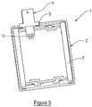
Figure 3 is a schematic cross-sectional view from below of the housing arrangement offigure 1 , -
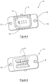
Figure 4 is a schematic perspective view of the front of a first connector of an embodiment of the invention, -
Figure 5 is a schematic perspective view of the rear of the connector shown infigure 4 , -
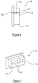
Figure 6 is a cross-sectional side view of a second connector of an embodiment of the invention, -
Figure 7 is a schematic perspective view of the second connector offigure 6 , -
Figure 8 is a schematic view of a second connector of a further embodiment which incorporates a membrane, -
Figure 9 is a schematic cross-sectional view of an embodiment of the invention with a first connector connected to a second connector, -
Figure 10 is a schematic cross-sectional view of a further embodiment of the invention with a first connector connected to a second connector, and -
Figure 11 is a schematic cross-sectional view of a housing arrangement of a yet further embodiment of the invention with a first connector connected to a second connector. - Referring now to
figures 1-3 of the accompanying drawings, ahousing arrangement 1 of an embodiment of the invention comprises ahousing 2 which is configured to house anelectrical device 3. Theelectrical device 3 comprises electronic circuitry and components that are protected physically by thehousing 2. - In embodiments of the invention, the
housing 2 is configured to house anelectrical device 3 for use in a vehicle, such as a radar sensor unit, an electronic control unit (ECU) or another type of vehicle sensor unit, processing unit or control unit. - The
housing arrangement 1 further comprises afirst connector 4 which is carried by thehousing 2. In some embodiments, thefirst connector 4 is formed integrally with thehousing 2 but in other embodiments thefirst connector 4 is a discrete component which is mounted to thehousing 2. - In this embodiment, the
first connector 4 is mounted to thehousing 2 to at least partly close anaperture 5 in thehousing 2. A sealing element or gasket (not visible infigure 3 ) is preferably provided between thefirst connector 4 and thehousing 2. The sealing element is preferably a waterproof gasket or seal which provides a watertight or substantially watertight seal around theaperture 5 to minimise or prevent moisture, water or other liquids from entering thehousing 2 through theaperture 5. - The sealing element is preferably of an elastically deformable material with an aperture having a shape that corresponds substantially to the shape of the
aperture 5 in thehousing 2. The sealing element is positioned so that the aperture in the sealing element is at least partly aligned with theaperture 5 in thehousing 2. Thefirst connector 4 is attached to thehousing 2 so that at least part of the sealing element is trapped between thehousing 2 and thefirst connector 4 to provide a watertight or substantially watertight seal between thefirst connector 4 and thehousing 2. - The
housing 2 comprises a base and a top cover (not shown) which provide a fluid or gas tight seal with the walls of thehousing 2 to enclose the interior of the housing. In other embodiments, the housing may be of a different shape to the one shown infigures 1-3 . - The
housing arrangement 2 is provided with abreather aperture 6 which permits air to flow out from the interior of thehousing 2 to the surrounding environment. The function of thebreather aperture 6 will be described in more detail below. - Referring now to
figure 4 of the accompanying drawings, thefirst connector 4 comprises a generallyplanar base 8 withmounting apertures first connector 4 to be mounted to thehousing 2. In some embodiments of the invention, such as the embodiment shown infigure 4 , thebreather aperture 6 is provided in a portion of the planar base of thefirst connector 4. - The
first connector 4 further comprises afirst connector formation 11 which is coupled to theplanar base 8 and extends at least partly around thebreather aperture 6. In some embodiments, such as the embodiment shown infigure 4 , thefirst connector formation 11 surrounds thebreather aperture 6 in the plane of base of thefirst connector 4. However, in other embodiments, thefirst connector formation 11 extends only partly around thebreather aperture 6. - In the embodiments described above, the
first connector formation 11 is a generally upstanding wall that extends around thebreather aperture 6. However, in further embodiments, the first connector formation is a generally downwardly extending wall that extends at least partly around thebreather aperture 6. For instance, in these further embodiments, the first connector formation is a channel or side wall that extends downwardly from the base of thefirst connector 4, adjacent to thebreather aperture 6. - In some embodiments, the
first connector 4 comprises an electrical contact provided on theplanar base 8 which is at least partly surrounded by thefirst connector formation 11. - Referring now to
figure 5 of the accompanying drawings, the housing arrangement of this embodiment comprises a plurality ofelectrical contacts 12 which extend through theplanar base 8 of thefirst connector 4 toelectrical contacts 13 which are provided on the rear side of thefirst connector 4. Theelectrical contacts 13 are configured to connect to theelectrical device 3 within thehousing 2. - Referring now to
figures 6 and 7 of the accompanying drawings, asecond connector 14 is configured to connect to thefirst connector 4. Thesecond connector 14 is, for instance, an electrical connector which is provided at the end of a cable (not shown) which is configured to be connected electrically to theelectrical device 3 within thehousing 2 via theconnectors - The
second connector 14 comprises asecond connector formation 15 which is configured to engage with thefirst connector formation 11 when the first andsecond connectors first connector formation 11 engages thesecond connector formation 15 such that the first andsecond connector formations breather aperture 6. The engagement of the first andsecond connectors connectors breather aperture 6. In the context of embodiments of the invention, the surrounding environment is the environment in the immediate vicinity of thefirst connector 4. - In some embodiments, a watertight sealing element or gasket (not shown) is provided on at least one of the first and
second connectors connectors connectors - In some embodiments, the
second connector 14 compriseselectrical contacts 16 which are configured to contact theelectrical contacts 12 on thefirst connector 4, when theconnectors - In this embodiment, the
second connector 14 is provided with afurther breather aperture 17. Thefurther breather aperture 17 is positioned so that thefurther breather aperture 17 is at least partly aligned with thebreather aperture 6 when the first andsecond connectors figure 9 . - In this embodiment, the
second connector 14 comprises abreather channel 17a which extends through the body of thesecond connector formation 15. Thefurther breather aperture 17 is provided at one end of thebreather channel 17a and anoutlet breather aperture 17b is provided at the other end of thebreather channel 17a - The
further breather aperture 17 cooperates with thefirst breather aperture 6 and thebreather channel 17a provides a continuous fluid flow path from the first breather aperture to the surrounding environment, through theoutlet breather aperture 17b. Thefurther breather aperture 17 therefore enables air flowing out from the interior of thehousing 7 via thebreather aperture 6 to escape to the surrounding environment. - Referring now to
figure 8 of the accompanying drawings, thefurther breather aperture 17 on thesecond connector 14 is at least partly closed by amembrane 18. Themembrane 18 is preferably of a material which enables fluid, such as air, to flow through themembrane 18 in one direction but which prevents fluid or debris, such as water or dirt, flowing through themembrane 18 in another direction. In other embodiments, themembrane 18 is omitted or replaced with a different one-way valve arrangement. - Referring now to
figure 10 of the accompanying drawings, a housing arrangement 19 of other embodiments of the invention comprises the same components as thehousing arrangement 1 described above. However, in these embodiments, thesecond connector 14 does not incorporate a further breather aperture. In these embodiments, thesecond connector formation 15 is configured to engage with thefirst connector formation 11 to form a watertight or substantially watertight seal. - When the
second connector 14 is connected to thefirst connector 4, acavity 20 is formed between thesecond connector 14, thehousing 2 and parts of thefirst connector 4. Thebreather aperture 6 provides a fluid flow path between theinterior chamber 7 of thehousing 2 and thecavity 20. In this embodiment, thecavity 20 provides a space into which air from thehousing 2 can flow when the pressure of the air within thehousing 2 is raised, for instance by hot electronic components within thehousing 2. The configuration of thecavity 20 therefore enables the air pressure within thehousing 2 to be reduced to protect thehousing 2. - Referring now to
figure 11 of the accompanying drawings, a housing arrangement 21 of other embodiments of the invention comprises the same components as the housing arrangement 19 of the further embodiment described above. However, in these other embodiments, there is a partial seal between the first andsecond connector formations housing 2 via thebreather aperture 6 can flow into thecavity 20 and then out into the surrounding environment through the partial seal between the first andsecond connector formations housing 2. - The
breather aperture 6 of embodiments of the invention reduces the air pressure within thehousing 2 to minimise damage to thehousing 2. When thesecond connector 14 is connected to thefirst connector 4, thebreather aperture 6 is at least partly closed or sealed which minimises the risk of fluid or dirt passing through thebreather aperture 6 and into theinterior chamber 7 of thehousing 2. - The
breather aperture 6 is at least partly surrounded or enclosed by the connector formations which minimises the risk of thebreather aperture 6 becoming blocked by fluid or dirt from the surrounding environment. - In embodiments where the
first connector 4 is a discrete component that is not formed integrally with thehousing 2, the first andsecond connectors - When used in this specification and the claims, the term "comprises" and "comprising" and variations thereof mean that specified features, steps or integers and included. The terms are not to be interpreted to exclude the presence of other features, steps or compounds.
- The features disclosed in the foregoing description, or the following claims, or the accompanying drawings, expressed in their specific forms or in terms of a means for performing the disclosed function, or a method or process for attaining the disclosed result, as appropriate, may, separately, or in any combination of such features, be utilised for realising the invention in diverse forms thereof.
Claims (15)
- A housing arrangement for use in a vehicle, the arrangement comprising:a housing configured to house an electrical device, the housing incorporating a breather aperture which permits air to flow out from the interior of the housing through the breather aperture; anda first connector which is carried by the housing, the first connector comprising a first connector formation which extends at least partly around the breather aperture, the first connector formation being configured to engage a second connector formation provided on a second connector such that the first and second connector formations at least partly block fluid in the surrounding environment from entering the breather aperture.
- The arrangement of claim 1, wherein the arrangement further comprises:a second connector comprising a second connector formation, the second connector being connected to the first connector such that the first and second connector formations at least partly block fluid in the surrounding environment from entering the housing through the breather aperture.
- A connector arrangement for use in a vehicle, the arrangement comprising:a first connector which is configured to be carried by a housing, the first connector incorporating a breather aperture which is configured to permit air to flow through part of the first connector such that, when the first connector is carried by a housing, air can flow out from the interior of the housing through the breather aperture, the first connector comprising a first connector formation which extends at least partly around the breather aperture; anda second connector comprising a second connector formation, the second connector being configured to connect to the first connector such that the first and second connector formations at least partly block fluid in the surrounding environment from entering the breather aperture.
- The arrangement of claim 2 or claim 3, wherein a cavity is formed between part of the second connector formation and the housing when the second connector is connected to the first connector, the cavity being in fluid communication with the breather aperture so that air can flow from the interior of the housing through the breather aperture and into the cavity.
- The arrangement of claim 4, wherein part of the second connector formation is configured to engage with part of the first connector formation to form a substantially gas tight seal which inhibits air escaping from the cavity into the surrounding environment.
- The arrangement of claim 4, wherein part of the second connector formation is configured to engage with part of the first connector formation to form a partial seal to permit air to flow out from the cavity into the surrounding environment between the first and second connector formations.
- The arrangement of any one of claims 2 to 6, wherein the second connector is provided with a further breather aperture which cooperates with the first breather aperture to provide a continuous fluid flow path from the first breather aperture to the surrounding environment through the further breather aperture.
- The arrangement of claim 7, wherein the further breather aperture is at least partly aligned with the breather aperture of the housing when the second connector is connected to the first connector.
- The arrangement of claim 7 or claim 8, wherein the second connector comprises a breather channel which provides a fluid flow path leading from the further breather aperture to the surrounding environment.
- The arrangement of any one of claims 7 to 9, wherein the further breather aperture is at least partly closed by a one-way valve arrangement.
- The arrangement of claim 10, wherein the one-way valve arrangement is a membrane which permits fluid to pass through the membrane in one direction but not in another direction.
- The arrangement of any one of claims 2 to 11, wherein a sealing element is provided on at least one of the first and second connectors to provide a substantially watertight seal between the first and second connectors when the first and second connectors are connected to one another.
- The arrangement of any one of the preceding claims, wherein the first connector comprises an electrical contact which is configured to engage an electrical contact on the second connector.
- An electronic control unit for use in a vehicle, the electronic control unit comprising the arrangement of any one of claims 1 to 12.
- A radar sensor unit for use in a vehicle, the radar sensor unit comprising the arrangement of any one of claims 1 to 12.
Priority Applications (1)
| Application Number | Priority Date | Filing Date | Title |
|---|---|---|---|
| EP17170792.0A EP3402009B1 (en) | 2017-05-12 | 2017-05-12 | A housing arrangement |
Applications Claiming Priority (1)
| Application Number | Priority Date | Filing Date | Title |
|---|---|---|---|
| EP17170792.0A EP3402009B1 (en) | 2017-05-12 | 2017-05-12 | A housing arrangement |
Publications (2)
| Publication Number | Publication Date |
|---|---|
| EP3402009A1 true EP3402009A1 (en) | 2018-11-14 |
| EP3402009B1 EP3402009B1 (en) | 2021-08-11 |
Family
ID=58707380
Family Applications (1)
| Application Number | Title | Priority Date | Filing Date |
|---|---|---|---|
| EP17170792.0A Active EP3402009B1 (en) | 2017-05-12 | 2017-05-12 | A housing arrangement |
Country Status (1)
| Country | Link |
|---|---|
| EP (1) | EP3402009B1 (en) |
Citations (4)
| Publication number | Priority date | Publication date | Assignee | Title |
|---|---|---|---|---|
| DE3635165A1 (en) * | 1986-10-16 | 1988-04-21 | Wabco Westinghouse Fahrzeug | HOUSING DEVICE WITH PRESSURE COMPENSATION |
| EP1168903A2 (en) * | 2000-06-28 | 2002-01-02 | Pierburg Aktiengesellschaft | Casing for electrical components for use in the automobile industry |
| DE10228948A1 (en) * | 2002-06-28 | 2004-01-22 | Hella Kg Hueck & Co. | Electrical device has encapsulated housing for electrical circuitry, and arrangement(s) for electrically connecting circuits in housing to electrical arrangements for connection outside housing |
| JP2009093906A (en) * | 2007-10-09 | 2009-04-30 | Sumitomo Wiring Syst Ltd | Water-proof connector |
-
2017
- 2017-05-12 EP EP17170792.0A patent/EP3402009B1/en active Active
Patent Citations (4)
| Publication number | Priority date | Publication date | Assignee | Title |
|---|---|---|---|---|
| DE3635165A1 (en) * | 1986-10-16 | 1988-04-21 | Wabco Westinghouse Fahrzeug | HOUSING DEVICE WITH PRESSURE COMPENSATION |
| EP1168903A2 (en) * | 2000-06-28 | 2002-01-02 | Pierburg Aktiengesellschaft | Casing for electrical components for use in the automobile industry |
| DE10228948A1 (en) * | 2002-06-28 | 2004-01-22 | Hella Kg Hueck & Co. | Electrical device has encapsulated housing for electrical circuitry, and arrangement(s) for electrically connecting circuits in housing to electrical arrangements for connection outside housing |
| JP2009093906A (en) * | 2007-10-09 | 2009-04-30 | Sumitomo Wiring Syst Ltd | Water-proof connector |
Also Published As
| Publication number | Publication date |
|---|---|
| EP3402009B1 (en) | 2021-08-11 |
Similar Documents
| Publication | Publication Date | Title |
|---|---|---|
| JP2000228243A (en) | Waterproof case ventilation structure | |
| CN106058558B (en) | waterproof connector | |
| US20110247952A1 (en) | Pressure-relief valve of a housing for an electrical/electronic unit | |
| KR101619860B1 (en) | Pressure compensation device and electronic control unit module containing the same | |
| US9992882B2 (en) | Electronic control unit | |
| US10149397B2 (en) | Protecting cover and electronic device assembly | |
| US11083097B2 (en) | Pressure-equalizing element and housing containing same | |
| CN101179910A (en) | Housing pressure equalization device | |
| JP6009604B1 (en) | Electrical junction box | |
| CN108353513A (en) | Closed structure of the machine housing | |
| JP6575347B2 (en) | Electronic equipment | |
| EP3402009B1 (en) | A housing arrangement | |
| CN115397146A (en) | Housing for electronic components and control unit | |
| JP2018533177A (en) | Sensor dome unit | |
| JP5685453B2 (en) | Filter member for connector, connector assembly, and assembly method of connector assembly | |
| CN209927349U (en) | Protective shell for electronic device and pressure sensor | |
| US7189922B1 (en) | Protective covers for electric components | |
| CA2891806C (en) | Water impermeable electrical junction system | |
| CN103973020B (en) | Band is useful for the shell of the protective device of wet-sealed device | |
| JP4119351B2 (en) | Control unit connector | |
| US20220087039A1 (en) | Pump unit comprising a connector with pressure compensation element | |
| JP2004356286A (en) | Circuit component equipment | |
| JP6269690B2 (en) | Outdoor unit | |
| JP5447975B2 (en) | Gas distribution unit | |
| CN107085455A (en) | Method for the protection shell of computer and for manufacturing such a shell |
Legal Events
| Date | Code | Title | Description |
|---|---|---|---|
| PUAI | Public reference made under article 153(3) epc to a published international application that has entered the european phase |
Free format text: ORIGINAL CODE: 0009012 |
|
| STAA | Information on the status of an ep patent application or granted ep patent |
Free format text: STATUS: THE APPLICATION HAS BEEN PUBLISHED |
|
| AK | Designated contracting states |
Kind code of ref document: A1 Designated state(s): AL AT BE BG CH CY CZ DE DK EE ES FI FR GB GR HR HU IE IS IT LI LT LU LV MC MK MT NL NO PL PT RO RS SE SI SK SM TR |
|
| AX | Request for extension of the european patent |
Extension state: BA ME |
|
| RAP1 | Party data changed (applicant data changed or rights of an application transferred) |
Owner name: VEONEER SWEDEN AB |
|
| STAA | Information on the status of an ep patent application or granted ep patent |
Free format text: STATUS: REQUEST FOR EXAMINATION WAS MADE |
|
| 17P | Request for examination filed |
Effective date: 20190513 |
|
| RBV | Designated contracting states (corrected) |
Designated state(s): AL AT BE BG CH CY CZ DE DK EE ES FI FR GB GR HR HU IE IS IT LI LT LU LV MC MK MT NL NO PL PT RO RS SE SI SK SM TR |
|
| STAA | Information on the status of an ep patent application or granted ep patent |
Free format text: STATUS: EXAMINATION IS IN PROGRESS |
|
| 17Q | First examination report despatched |
Effective date: 20200819 |
|
| GRAP | Despatch of communication of intention to grant a patent |
Free format text: ORIGINAL CODE: EPIDOSNIGR1 |
|
| STAA | Information on the status of an ep patent application or granted ep patent |
Free format text: STATUS: GRANT OF PATENT IS INTENDED |
|
| INTG | Intention to grant announced |
Effective date: 20210331 |
|
| GRAS | Grant fee paid |
Free format text: ORIGINAL CODE: EPIDOSNIGR3 |
|
| GRAA | (expected) grant |
Free format text: ORIGINAL CODE: 0009210 |
|
| STAA | Information on the status of an ep patent application or granted ep patent |
Free format text: STATUS: THE PATENT HAS BEEN GRANTED |
|
| AK | Designated contracting states |
Kind code of ref document: B1 Designated state(s): AL AT BE BG CH CY CZ DE DK EE ES FI FR GB GR HR HU IE IS IT LI LT LU LV MC MK MT NL NO PL PT RO RS SE SI SK SM TR |
|
| REG | Reference to a national code |
Ref country code: CH Ref legal event code: EP |
|
| REG | Reference to a national code |
Ref country code: DE Ref legal event code: R096 Ref document number: 602017043694 Country of ref document: DE |
|
| REG | Reference to a national code |
Ref country code: IE Ref legal event code: FG4D Ref country code: AT Ref legal event code: REF Ref document number: 1420354 Country of ref document: AT Kind code of ref document: T Effective date: 20210915 |
|
| REG | Reference to a national code |
Ref country code: LT Ref legal event code: MG9D |
|
| REG | Reference to a national code |
Ref country code: NL Ref legal event code: MP Effective date: 20210811 |
|
| REG | Reference to a national code |
Ref country code: AT Ref legal event code: MK05 Ref document number: 1420354 Country of ref document: AT Kind code of ref document: T Effective date: 20210811 |
|
| PG25 | Lapsed in a contracting state [announced via postgrant information from national office to epo] |
Ref country code: SE Free format text: LAPSE BECAUSE OF FAILURE TO SUBMIT A TRANSLATION OF THE DESCRIPTION OR TO PAY THE FEE WITHIN THE PRESCRIBED TIME-LIMIT Effective date: 20210811 Ref country code: RS Free format text: LAPSE BECAUSE OF FAILURE TO SUBMIT A TRANSLATION OF THE DESCRIPTION OR TO PAY THE FEE WITHIN THE PRESCRIBED TIME-LIMIT Effective date: 20210811 Ref country code: AT Free format text: LAPSE BECAUSE OF FAILURE TO SUBMIT A TRANSLATION OF THE DESCRIPTION OR TO PAY THE FEE WITHIN THE PRESCRIBED TIME-LIMIT Effective date: 20210811 Ref country code: BG Free format text: LAPSE BECAUSE OF FAILURE TO SUBMIT A TRANSLATION OF THE DESCRIPTION OR TO PAY THE FEE WITHIN THE PRESCRIBED TIME-LIMIT Effective date: 20211111 Ref country code: LT Free format text: LAPSE BECAUSE OF FAILURE TO SUBMIT A TRANSLATION OF THE DESCRIPTION OR TO PAY THE FEE WITHIN THE PRESCRIBED TIME-LIMIT Effective date: 20210811 Ref country code: PT Free format text: LAPSE BECAUSE OF FAILURE TO SUBMIT A TRANSLATION OF THE DESCRIPTION OR TO PAY THE FEE WITHIN THE PRESCRIBED TIME-LIMIT Effective date: 20211213 Ref country code: NO Free format text: LAPSE BECAUSE OF FAILURE TO SUBMIT A TRANSLATION OF THE DESCRIPTION OR TO PAY THE FEE WITHIN THE PRESCRIBED TIME-LIMIT Effective date: 20211111 Ref country code: HR Free format text: LAPSE BECAUSE OF FAILURE TO SUBMIT A TRANSLATION OF THE DESCRIPTION OR TO PAY THE FEE WITHIN THE PRESCRIBED TIME-LIMIT Effective date: 20210811 Ref country code: ES Free format text: LAPSE BECAUSE OF FAILURE TO SUBMIT A TRANSLATION OF THE DESCRIPTION OR TO PAY THE FEE WITHIN THE PRESCRIBED TIME-LIMIT Effective date: 20210811 Ref country code: FI Free format text: LAPSE BECAUSE OF FAILURE TO SUBMIT A TRANSLATION OF THE DESCRIPTION OR TO PAY THE FEE WITHIN THE PRESCRIBED TIME-LIMIT Effective date: 20210811 |
|
| PG25 | Lapsed in a contracting state [announced via postgrant information from national office to epo] |
Ref country code: PL Free format text: LAPSE BECAUSE OF FAILURE TO SUBMIT A TRANSLATION OF THE DESCRIPTION OR TO PAY THE FEE WITHIN THE PRESCRIBED TIME-LIMIT Effective date: 20210811 Ref country code: LV Free format text: LAPSE BECAUSE OF FAILURE TO SUBMIT A TRANSLATION OF THE DESCRIPTION OR TO PAY THE FEE WITHIN THE PRESCRIBED TIME-LIMIT Effective date: 20210811 Ref country code: GR Free format text: LAPSE BECAUSE OF FAILURE TO SUBMIT A TRANSLATION OF THE DESCRIPTION OR TO PAY THE FEE WITHIN THE PRESCRIBED TIME-LIMIT Effective date: 20211112 |
|
| PG25 | Lapsed in a contracting state [announced via postgrant information from national office to epo] |
Ref country code: NL Free format text: LAPSE BECAUSE OF FAILURE TO SUBMIT A TRANSLATION OF THE DESCRIPTION OR TO PAY THE FEE WITHIN THE PRESCRIBED TIME-LIMIT Effective date: 20210811 |
|
| PG25 | Lapsed in a contracting state [announced via postgrant information from national office to epo] |
Ref country code: DK Free format text: LAPSE BECAUSE OF FAILURE TO SUBMIT A TRANSLATION OF THE DESCRIPTION OR TO PAY THE FEE WITHIN THE PRESCRIBED TIME-LIMIT Effective date: 20210811 |
|
| REG | Reference to a national code |
Ref country code: DE Ref legal event code: R097 Ref document number: 602017043694 Country of ref document: DE |
|
| REG | Reference to a national code |
Ref country code: DE Ref legal event code: R081 Ref document number: 602017043694 Country of ref document: DE Owner name: ARRIVER SOFTWARE AB, SE Free format text: FORMER OWNER: VEONEER SWEDEN AB, VARGARDA, SE Ref country code: DE Ref legal event code: R081 Ref document number: 602017043694 Country of ref document: DE Owner name: QUALCOMM AUTO LTD., CAMBRIDGE, GB Free format text: FORMER OWNER: VEONEER SWEDEN AB, VARGARDA, SE |
|
| PG25 | Lapsed in a contracting state [announced via postgrant information from national office to epo] |
Ref country code: SM Free format text: LAPSE BECAUSE OF FAILURE TO SUBMIT A TRANSLATION OF THE DESCRIPTION OR TO PAY THE FEE WITHIN THE PRESCRIBED TIME-LIMIT Effective date: 20210811 Ref country code: SK Free format text: LAPSE BECAUSE OF FAILURE TO SUBMIT A TRANSLATION OF THE DESCRIPTION OR TO PAY THE FEE WITHIN THE PRESCRIBED TIME-LIMIT Effective date: 20210811 Ref country code: RO Free format text: LAPSE BECAUSE OF FAILURE TO SUBMIT A TRANSLATION OF THE DESCRIPTION OR TO PAY THE FEE WITHIN THE PRESCRIBED TIME-LIMIT Effective date: 20210811 Ref country code: EE Free format text: LAPSE BECAUSE OF FAILURE TO SUBMIT A TRANSLATION OF THE DESCRIPTION OR TO PAY THE FEE WITHIN THE PRESCRIBED TIME-LIMIT Effective date: 20210811 Ref country code: CZ Free format text: LAPSE BECAUSE OF FAILURE TO SUBMIT A TRANSLATION OF THE DESCRIPTION OR TO PAY THE FEE WITHIN THE PRESCRIBED TIME-LIMIT Effective date: 20210811 Ref country code: AL Free format text: LAPSE BECAUSE OF FAILURE TO SUBMIT A TRANSLATION OF THE DESCRIPTION OR TO PAY THE FEE WITHIN THE PRESCRIBED TIME-LIMIT Effective date: 20210811 |
|
| PLBE | No opposition filed within time limit |
Free format text: ORIGINAL CODE: 0009261 |
|
| STAA | Information on the status of an ep patent application or granted ep patent |
Free format text: STATUS: NO OPPOSITION FILED WITHIN TIME LIMIT |
|
| 26N | No opposition filed |
Effective date: 20220512 |
|
| PG25 | Lapsed in a contracting state [announced via postgrant information from national office to epo] |
Ref country code: IT Free format text: LAPSE BECAUSE OF FAILURE TO SUBMIT A TRANSLATION OF THE DESCRIPTION OR TO PAY THE FEE WITHIN THE PRESCRIBED TIME-LIMIT Effective date: 20210811 |
|
| PG25 | Lapsed in a contracting state [announced via postgrant information from national office to epo] |
Ref country code: SI Free format text: LAPSE BECAUSE OF FAILURE TO SUBMIT A TRANSLATION OF THE DESCRIPTION OR TO PAY THE FEE WITHIN THE PRESCRIBED TIME-LIMIT Effective date: 20210811 |
|
| REG | Reference to a national code |
Ref country code: CH Ref legal event code: PL |
|
| REG | Reference to a national code |
Ref country code: BE Ref legal event code: MM Effective date: 20220531 |
|
| PG25 | Lapsed in a contracting state [announced via postgrant information from national office to epo] |
Ref country code: MC Free format text: LAPSE BECAUSE OF FAILURE TO SUBMIT A TRANSLATION OF THE DESCRIPTION OR TO PAY THE FEE WITHIN THE PRESCRIBED TIME-LIMIT Effective date: 20210811 Ref country code: LU Free format text: LAPSE BECAUSE OF NON-PAYMENT OF DUE FEES Effective date: 20220512 Ref country code: LI Free format text: LAPSE BECAUSE OF NON-PAYMENT OF DUE FEES Effective date: 20220531 Ref country code: CH Free format text: LAPSE BECAUSE OF NON-PAYMENT OF DUE FEES Effective date: 20220531 |
|
| PG25 | Lapsed in a contracting state [announced via postgrant information from national office to epo] |
Ref country code: IE Free format text: LAPSE BECAUSE OF NON-PAYMENT OF DUE FEES Effective date: 20220512 |
|
| PG25 | Lapsed in a contracting state [announced via postgrant information from national office to epo] |
Ref country code: BE Free format text: LAPSE BECAUSE OF NON-PAYMENT OF DUE FEES Effective date: 20220531 |
|
| PG25 | Lapsed in a contracting state [announced via postgrant information from national office to epo] |
Ref country code: HU Free format text: LAPSE BECAUSE OF FAILURE TO SUBMIT A TRANSLATION OF THE DESCRIPTION OR TO PAY THE FEE WITHIN THE PRESCRIBED TIME-LIMIT; INVALID AB INITIO Effective date: 20170512 |
|
| PG25 | Lapsed in a contracting state [announced via postgrant information from national office to epo] |
Ref country code: MK Free format text: LAPSE BECAUSE OF FAILURE TO SUBMIT A TRANSLATION OF THE DESCRIPTION OR TO PAY THE FEE WITHIN THE PRESCRIBED TIME-LIMIT Effective date: 20210811 Ref country code: CY Free format text: LAPSE BECAUSE OF FAILURE TO SUBMIT A TRANSLATION OF THE DESCRIPTION OR TO PAY THE FEE WITHIN THE PRESCRIBED TIME-LIMIT Effective date: 20210811 |
|
| REG | Reference to a national code |
Ref country code: GB Ref legal event code: 732E Free format text: REGISTERED BETWEEN 20240418 AND 20240424 |
|
| PG25 | Lapsed in a contracting state [announced via postgrant information from national office to epo] |
Ref country code: MT Free format text: LAPSE BECAUSE OF FAILURE TO SUBMIT A TRANSLATION OF THE DESCRIPTION OR TO PAY THE FEE WITHIN THE PRESCRIBED TIME-LIMIT Effective date: 20210811 |
|
| REG | Reference to a national code |
Ref country code: DE Ref legal event code: R081 Ref document number: 602017043694 Country of ref document: DE Owner name: QUALCOMM AUTO LTD., CAMBRIDGE, GB Free format text: FORMER OWNER: ARRIVER SOFTWARE AB, LINKOEPING, SE |
|
| PGFP | Annual fee paid to national office [announced via postgrant information from national office to epo] |
Ref country code: DE Payment date: 20250409 Year of fee payment: 9 |
|
| PGFP | Annual fee paid to national office [announced via postgrant information from national office to epo] |
Ref country code: FR Payment date: 20250409 Year of fee payment: 9 |
|
| PG25 | Lapsed in a contracting state [announced via postgrant information from national office to epo] |
Ref country code: TR Free format text: LAPSE BECAUSE OF FAILURE TO SUBMIT A TRANSLATION OF THE DESCRIPTION OR TO PAY THE FEE WITHIN THE PRESCRIBED TIME-LIMIT Effective date: 20210811 |
|
| PGFP | Annual fee paid to national office [announced via postgrant information from national office to epo] |
Ref country code: GB Payment date: 20260320 Year of fee payment: 10 |