EP3401734A1 - Feeding assembly for loading a flexographic plate in a treatment station - Google Patents
Feeding assembly for loading a flexographic plate in a treatment station Download PDFInfo
- Publication number
- EP3401734A1 EP3401734A1 EP18171690.3A EP18171690A EP3401734A1 EP 3401734 A1 EP3401734 A1 EP 3401734A1 EP 18171690 A EP18171690 A EP 18171690A EP 3401734 A1 EP3401734 A1 EP 3401734A1
- Authority
- EP
- European Patent Office
- Prior art keywords
- plate
- bar
- pin
- assembly
- punching
- Prior art date
- Legal status (The legal status is an assumption and is not a legal conclusion. Google has not performed a legal analysis and makes no representation as to the accuracy of the status listed.)
- Granted
Links
Images


Classifications
-
- G—PHYSICS
- G03—PHOTOGRAPHY; CINEMATOGRAPHY; ANALOGOUS TECHNIQUES USING WAVES OTHER THAN OPTICAL WAVES; ELECTROGRAPHY; HOLOGRAPHY
- G03F—PHOTOMECHANICAL PRODUCTION OF TEXTURED OR PATTERNED SURFACES, e.g. FOR PRINTING, FOR PROCESSING OF SEMICONDUCTOR DEVICES; MATERIALS THEREFOR; ORIGINALS THEREFOR; APPARATUS SPECIALLY ADAPTED THEREFOR
- G03F7/00—Photomechanical, e.g. photolithographic, production of textured or patterned surfaces, e.g. printing surfaces; Materials therefor, e.g. comprising photoresists; Apparatus specially adapted therefor
- G03F7/26—Processing photosensitive materials; Apparatus therefor
- G03F7/30—Imagewise removal using liquid means
- G03F7/3042—Imagewise removal using liquid means from printing plates transported horizontally through the processing stations
- G03F7/3057—Imagewise removal using liquid means from printing plates transported horizontally through the processing stations characterised by the processing units other than the developing unit, e.g. washing units
-
- B—PERFORMING OPERATIONS; TRANSPORTING
- B41—PRINTING; LINING MACHINES; TYPEWRITERS; STAMPS
- B41F—PRINTING MACHINES OR PRESSES
- B41F27/00—Devices for attaching printing elements or formes to supports
- B41F27/14—Devices for attaching printing elements or formes to supports for attaching printing formes to intermediate supports, e.g. adapter members
-
- G—PHYSICS
- G03—PHOTOGRAPHY; CINEMATOGRAPHY; ANALOGOUS TECHNIQUES USING WAVES OTHER THAN OPTICAL WAVES; ELECTROGRAPHY; HOLOGRAPHY
- G03F—PHOTOMECHANICAL PRODUCTION OF TEXTURED OR PATTERNED SURFACES, e.g. FOR PRINTING, FOR PROCESSING OF SEMICONDUCTOR DEVICES; MATERIALS THEREFOR; ORIGINALS THEREFOR; APPARATUS SPECIALLY ADAPTED THEREFOR
- G03F7/00—Photomechanical, e.g. photolithographic, production of textured or patterned surfaces, e.g. printing surfaces; Materials therefor, e.g. comprising photoresists; Apparatus specially adapted therefor
- G03F7/20—Exposure; Apparatus therefor
- G03F7/2002—Exposure; Apparatus therefor with visible light or UV light, through an original having an opaque pattern on a transparent support, e.g. film printing, projection printing; by reflection of visible or UV light from an original such as a printed image
- G03F7/2004—Exposure; Apparatus therefor with visible light or UV light, through an original having an opaque pattern on a transparent support, e.g. film printing, projection printing; by reflection of visible or UV light from an original such as a printed image characterised by the use of a particular light source, e.g. fluorescent lamps or deep UV light
-
- G—PHYSICS
- G03—PHOTOGRAPHY; CINEMATOGRAPHY; ANALOGOUS TECHNIQUES USING WAVES OTHER THAN OPTICAL WAVES; ELECTROGRAPHY; HOLOGRAPHY
- G03F—PHOTOMECHANICAL PRODUCTION OF TEXTURED OR PATTERNED SURFACES, e.g. FOR PRINTING, FOR PROCESSING OF SEMICONDUCTOR DEVICES; MATERIALS THEREFOR; ORIGINALS THEREFOR; APPARATUS SPECIALLY ADAPTED THEREFOR
- G03F7/00—Photomechanical, e.g. photolithographic, production of textured or patterned surfaces, e.g. printing surfaces; Materials therefor, e.g. comprising photoresists; Apparatus specially adapted therefor
- G03F7/20—Exposure; Apparatus therefor
- G03F7/2022—Multi-step exposure, e.g. hybrid; backside exposure; blanket exposure, e.g. for image reversal; edge exposure, e.g. for edge bead removal; corrective exposure
- G03F7/2032—Simultaneous exposure of the front side and the backside
-
- G—PHYSICS
- G03—PHOTOGRAPHY; CINEMATOGRAPHY; ANALOGOUS TECHNIQUES USING WAVES OTHER THAN OPTICAL WAVES; ELECTROGRAPHY; HOLOGRAPHY
- G03F—PHOTOMECHANICAL PRODUCTION OF TEXTURED OR PATTERNED SURFACES, e.g. FOR PRINTING, FOR PROCESSING OF SEMICONDUCTOR DEVICES; MATERIALS THEREFOR; ORIGINALS THEREFOR; APPARATUS SPECIALLY ADAPTED THEREFOR
- G03F7/00—Photomechanical, e.g. photolithographic, production of textured or patterned surfaces, e.g. printing surfaces; Materials therefor, e.g. comprising photoresists; Apparatus specially adapted therefor
- G03F7/26—Processing photosensitive materials; Apparatus therefor
- G03F7/30—Imagewise removal using liquid means
- G03F7/3042—Imagewise removal using liquid means from printing plates transported horizontally through the processing stations
- G03F7/3064—Imagewise removal using liquid means from printing plates transported horizontally through the processing stations characterised by the transport means or means for confining the different units, e.g. to avoid the overflow
Definitions
- the present invention relates to the field of manufacturing digital printing plates for flexography.
- the present invention relates to a feeding assembly for automatically inserting a flexographic plate inside a treatment station which may be, for example, a washing station or an exposure station.
- the invention also relates to a system comprising at least one treatment station and at least one feeding assembly according to the present invention.
- Flexography is a direct rotary printing method which employs plates in relief made of photo-polymeric materials.
- the plates are flexible and soft, hence the name flexography.
- Such plates are inked and the print is obtained by means of direct deposition of the ink on the medium to be printed by virtue of a slight pressure exerted by a printing cylinder on which the plates are positioned.
- Flexography is a high-speed printing process, capable of printing on many types of absorbing and non-absorbing materials. Some typical applications of flexographic printing are the production of paper and plastic bags, milk cartons, disposable cups and the like, but by virtue of the progress in printing quality, flexography is today also used for printing newspapers, for example, as well as packets and labels and for printing on plastic, films and acetate sheets, packing paper and on many other materials used for product packaging.
- Digital flexography is a particular type of flexographic printing in which digital plates are used.
- the photo-polymer is originally covered by a surface layer of material which prevents photo-exposure, such as for example a carbon or graphite layer.
- a layer of material is etched so as to create the negative image of the print subject.
- Such a step of etching is usually performed by means of a digital laser, controlled by a computer (hence the acronym CTP " Computer To Plate " used to indicate this step of the pre-printing process in the sector).
- CTP Computer To Plate
- Patent application EP 2839345 by the Applicant, for example, describes a system comprising a washing station in line with an exposure station and moving means which allow a continuous movement of the plate between the two treatment stations.
- Patent application WO 2016/030450 describes an in-line system conceptually similar to the one described in EP 2839345 , in which a drying station of the flexographic plates is provided downstream of the washing station. Such a system comprises automatic moving means which pick the plates let out from the washing station and store them in specific drying boxes.
- the photo-exposure of the plate is performed in an autonomous treatment station, i.e. separated from the rest of the system comprising the washing station and the drying station.
- patent application EP 3121653 describes an autonomous station for the photo-exposure of digital plates. In this case, at the end of the photo-exposure, the digital plate is picked and loaded into the washing station of the system. The latter may or may not be in line with the drying station.
- the plates are typically advanced through the treatment stations by using a pin bar to which the plate is coupled.
- a pin bar comprises a row of pins configured to be inserted into corresponding holes defined near a front edge of the plate, where the word "front” refers to the edge of the plate facing downstream with respect to a feeding direction of the plate.
- the pin bar is fed into the treatment station by means of a dragging system which is inside the station itself. More precisely, this system is configured to couple the opposite ends of the pin bar and to move it along said advancement direction. During such an advancement, the pin bar maintains an alignment direction transversal to the advancement direction by dragging the digital plate coupled thereto.
- the connection between plate and pin bar always requires a manual intervention.
- an operator firstly proceeds by piercing a plurality of holes through the plate in which the pins of the bar can be inserted.
- a punching device in nearly all cases separate from the rest of the system, is used for this purpose.
- the operator proceeds by manually connecting the plate to the pin bar (by inserting the pins into corresponding holes) and positioning the pin bar in a predetermined position near the inlet of the treatment station. In such a position, the pin bar can be coupled and dragged, together with the plate, by the dragging system inside the treatment station.
- the feeding of an in-line plant and more in general of a treatment station, currently requires the manual intervention of an operator to load the plate, to connect the plate to the pin bar and finally to place the latter in the predetermined position for coupling it to the dragging system inside the first treatment station of the system.
- the need for a manual intervention is also found in systems in which the photo-exposure station is autonomous with respect to the in-line plant, in which the first treatment station is the washing station. In this case, the operator is required to perform a further intervention to physically transport the plate exiting from the exposure station to the punching device.
- a feeding assembly for automatically loading a flexographic plate in a treatment station, which allows to overcome the drawbacks of the prior art.
- a feeding assembly which is reliable and easy to be manufactured at competitive costs.
- the present invention thus relates to a feeding assembly for automatically loading a flexographic plate in a treatment station.
- the assembly according to the invention is characterized in that it comprises:
- the handling means of the feeding assembly further comprise:
- the feeding assembly according to the invention allows to connect automatically a flexographic plate to a pin bar while loading, again automatically, said pin bar into a treatment station of the plate.
- the feeding assembly according to the invention may be used to load a flexographic plate into the first station of an in-line treatment system but could be used for feeding a totally autonomous treatment station.
- the present invention thus relates to a feeding assembly 1 for automatically inserting/loading a flexographic plate 5 in a treatment station 7 of the plate itself.
- the assembly 1 according to the invention is configured to connect, in automatic manner and without intervention by an operator, the plate 5 to a pin bar 14 intended to be dragged through the treatment station 7 by means of a dragging system.
- the expression pin bar 14 (or more simply bar 14) indicates a body, preferably plate-shaped, which identifies a main direction of development 105.
- the bar 14 comprises a plurality of pins 15 which emerge from a same side of the body and which are aligned along a direction parallel to the main direction 105.
- Figure 1 is a diagrammatic plan view of a treatment system of flexographic plates comprising an assembly 1 according to the invention.
- the assembly 1 is operatively interposed between a first exposure station 6 and a washing station 7.
- the latter could be the first station of a system comprising several stations in line.
- the assembly 1 according to the invention can also be used for loading plates in an in-line system in which the first station is an exposure station.
- the assembly 1 can also be used to load a flexographic plate in an entirely autonomous treatment station (washing, exposure, drying), i.e. not in line with other stations.
- the feeding assembly 1 comprises a loading surface 2 on which the plate 5 is placed designed to be loaded in the treatment station 7.
- a loading surface identifies a substantially horizontal reference plane 101'.
- the plate 5 is automatically placed on the loading surface 2.
- the exposure station 6 is arranged in a lateral position, vicinal to the loading surface 2 so that the plate 5, at the exposure station 6 outlet, lands directly onto the loading surface 2.
- the system could comprise two exposure stations arranged on opposite sides of the loading surface 2.
- the feeding assembly 1 further comprises an advancement surface substantially defined between the loading surface 2 and an inlet section 71 of the treatment station 7 in which the plate 5 must be loaded.
- advancement surface indicates a set of parts which define, as a whole, a substantially horizontal reference plane 101, along which the plate 5 rests, either completely or partially, during its movement toward the treatment station 7.
- the reference plane 101' defined by the loading surface 2 and the reference plane 101 are coplanar.
- the assembly 1 comprises handling means 45,50 of the plate 5 configured to move the plate 5 between the loading surface 2 and the inlet section 71 of the treatment station 7.
- the handling means 45,50 may intervene either directly or indirectly (through the bar 14 pins) on the plate 5 according to the principles set out below.
- the moving means 45,50 define a longitudinal direction 201 of displacement along which the plate 5 is moved.
- the expression "transversal direction 202” instead, means a direction substantially orthogonal to the longitudinal direction 201.
- vertical direction 203 means a direction orthogonal to the surface defined by directions 201 and 202.
- the assembly 1 comprises a punching unit 30 comprising punching means 35 which, in an activation configuration thereof, pierce a row of connecting holes 55 through the plate 5 (see Figure 7 ).
- the punching means 35 are configured to provide holes 55, the shape of which is such as to allow the insertion of a pin 15 of said rod 14 into each of them.
- the punching unit 30 is located downstream of the loading surface 2, preferably in a position adjacent thereto.
- the assembly 1 further comprises a housing site 40 in which the bar 14 is accommodated. More precisely, the bar 14 is oriented in a transversal direction, i.e. so that the respective pins 15 are aligned along the transversal direction 202 (orthogonal to the longitudinal direction 201).
- the handling means of the plate 5 comprise a first handling unit 50 which moves the plate 5 along the longitudinal direction 201 to take a front edge 5' thereof to a first longitudinal reference position (indicated by P1) upon the reaching of which the punching means 35 are activated to carry out a row of connection holes 55 through the plate itself near said front edge 5'.
- the handling means of the plate 5 also comprise a second handling unit 45 to move the plate 5 following the formation of the connection holes 55.
- the second handling unit 45 raises and moves the plate 5 along the longitudinal direction 201 to a second reference longitudinal position (indicated by P2).
- said second position is such that the connection holes 55 are aligned with the pins 15 of the bar 14.
- the second handling unit 45 moves the plate 5 until an alignment position is reached such that the axis of each hole 55 is substantially aligned with the axis of a corresponding pin 15.
- the second handling unit 45 releases the plate 5 preferably in such a condition that the plate 5 itself, at the connection holes 55, rests against the pins 15 of the pin bar 14 (preferred alignment condition).
- the assembly 1 comprises a pressing device 70 which acts on the plate 5 to connect it to the bar 14. More precisely, the pressing device 70 presses the plate 5 near the connection holes so that each pin 15 is inserted in a corresponding hole 55.
- the pressing device 70 is configured to apply a thrust/localized pressure around each hole 55, which in said second position P2, is precisely aligned with a corresponding pin 15. This localized pressure is such as to push the plate region about the hole 55 at the base of the corresponding pin 15, thus ensuring its complete insertion in the respective hole and thus allowing the connection of the plate 5 to the hole 55, as a whole.
- the pressing device 70 is movable in the transversal direction 202, so as to intervene in succession/sequence on each hole-pin pair.
- the pressing device 70 may be shaped so as to act simultaneously on each pin-hole pair, i.e. so that all the pins 15 are inserted simultaneously into the corresponding holes 55.
- the second handling unit 45 lifts the bar 14 (with which the plate 5 has become integral) and moves it to a third reference position P3 at which the pin bar 14 can be coupled with the dragging system 77 of the treatment station 7.
- the second handling unit 45 intervenes directly on the plate 5 in the first operative step, while it intervenes directly on the pin bar 14 in the second operative step. So, in this second operative step, the second handling unit 45 handles the plate 5 in an indirect manner precisely through the bar 14.
- the second handling unit 45 raises a front portion 5a of the plate 5 near said front edge 5' in the first operative step.
- the second position P2 is such that each of the holes 55 takes a position substantially over a corresponding pin 15 of said pin bar 14 (see Figure 7 ).
- the second handling unit 45 translates the front portion 5a of the plate 5 downwards (i.e. lowered towards the advancement surface) so it rests on the pins 15 at the holes 55.
- the second handling unit 45 aligns the holes 55 with the pins 15 thus preparing the successive intervention of the pressing device 70.
- the punching units 30 preferably takes a retracted configuration and an emerging configuration with respect to the reference plane 101.
- the punching unit 30 In the retracted configuration (diagrammatically shown in Figure 9 ), the punching unit 30 is substantially under the reference plane 101 so as not to hinder the movement of the plate 5 along the longitudinal direction 201.
- the punching means 35 In the emerging configuration (diagrammatically shown in Figure 10 ), the punching means 35 are located at a predetermined height with respect to the reference plane 101, upon the reaching of which they can carry out holes 55 through the plate 5.
- the punching unit 30 is substantially " retractable " , meaning that disappears, when deactivated, below the reference plane 101.
- the punching unit 30 comprises an upper plate 35' to which the punching means 35 are attached.
- the upper plate 35' defines a portion of the advancement surface when the punching unit 30 takes the retracted configuration.
- the punching means 35 are fastened to the lower side of the upper plate 35'.
- the upper plate 35' extends mainly along the transversal direction 202 for a width (indicated by 301) preferably close to that of the loading surface 2.
- the upper plate 35' has a substantially rectangular shape, seen from the top.
- the punching means 35 comprise a body 36 which extends prevalently in the transversal direction 202 for a length substantially close to the width 301 of the upper plate 35'.
- a body 36 defines a cavity 37 facing the loading surface 2 into which a front portion 5A of said plate 5 can be inserted, and preferably supported. More precisely, the body 36 and the cavity 37 have a transversal extension such as to allow the front portion 5A to be inserted for the whole length thereof.
- the punching means 35 comprise a plurality of punching elements 38, each of which serves to carry out one of the connection holes 55.
- the punching elements 38 are aligned along a direction parallel to the transversal direction 202 and, in an activation configuration, move vertically with respect to the body 36 so that their ends penetrate through the plate 5, whereby configuring the coupling holes 55 according to a principle can be easily inferred.
- the cavity 37 of the body 36 defines an abutment surface 39 for a front edge 5' of the plate 5.
- a abutment surface 39 extends parallel to the transversal direction 202.
- the abutment surface 39 establishes the first reference position P1 indicated above.
- the first handling unit 50 moves the plate 5 until its front edge 5' comes into contact with the abutment surface 39.
- the punching means 35 are activated so that the punching elements 38 pierce the connection holes 55 through the plate 5.
- the punching unit 30 comprises lifting means 34 (indicated in Figure 2 ) which raise and lower the upper plate 35', and more in general the punching means 35, with respect to the reference plane 101.
- lifting means may comprise electric actuators which act on the opposite ends of the upper plate 35' and/or on the opposite ends of the body 36 of the punching means 35.
- lifting means 34 may be installed on the supporting frame 90 which supports the parts defining the advancement surface.
- the housing site 40 is operatively positioned downstream of the punching unit 30 and preferably in a position substantially adjacent to the inlet section 71 of the treatment station 7.
- the housing site 40 is defined by a supporting plate 41 supported by the sides 91 of the frame 90. As a whole, the frame 90 supports the advancement surface.
- the pin bar 14 rests on the plate 41 with a side opposite to the one from which the pins 15 emerge.
- the housing site 40 comprises removable locking means which lock the bar 14 in a predetermined longitudinal position.
- the locking means comprise a pair of locking modules 49, each of which is installed on a side 8 of the supporting frame 90 to intervene on a corresponding end 14A,14B of the bar 14.
- Such modules 49 comprise an actuator 42 which moves a locking pin 43 between a retracted position in which it does not interact with the bar 14, and an extended position.
- the locking pin 43 is inserted in a cavity 16 defined at an end 14A, 14B of bar 14 so as to lock the translation of the bar itself on the moving surface.
- the locking condition is maintained until the connection between plate 5 and bar 14 has been finally completed. Having reached this condition, the locking means are deactivated so as to allow the second handling unit 45 to move the pin bar 14 from the housing site 40 up to the third reference position P3 in which it will be coupled by the dragging system 77 of the treatment station 7.
- FIGS 7 and 8 diagrammatically show in detail the step of connecting the plate 5 to the pin bar 14; according to that indicated above, such a connection is made at the housing site 40 and following the displacement of the plate 5, made by the second handling unit 45, up to the second position P2.
- each hole 55 of the plate 5 takes a position substantially over a corresponding pin 15 of the bar 14, i.e. the axis of each hole 55 is substantially aligned with the axis of the corresponding pin 15.
- the connection between plate 5 and pins 15 is obtained by activating the pressing device 70.
- the pressing device 70 is preferably configured to apply a localized pressure on the plate 5 about the edge of a hole 55 aligned with a corresponding pin 15.
- the pressing device 70 is configured to apply a pressure which is such as to locally push the plate 5 at the base of said corresponding pin 15, whereby guaranteeing full insertion in the corresponding hole 55.
- the pressing device 70 is structurally independent from the second handling unit 45 and is movable in the transversal direction 202 to intervene at each pair hole-pin, the word " pair " indicating a hole 55 and the corresponding pin 15.
- the pressing unit 70 preferably comprises an actuator 71 (either electric or pneumatic) mounted by means of a supporting arm 73 on a slide 72 movable along the transversal direction 202.
- an actuator 71 vertically moves a presser 74 comprising a cylindrical end 74A which defines a cavity 75 in which the head 15A of a pin 15 of the bar 14 can be inserted.
- the actuator 71 moves the presser 74 vertically (arrow 404) between a raised non-intervention position and a lowered intervention position.
- the head 15A of the pin 15 is inserted into the cavity of the presser 74, while the edge of the cylindrical end 74A locally pushes the portion of plate 5 about the hole 55 to the base of the pin 15.
- the presser device 70 has treated all the hole-pin pairs in sequence, the plate 5 is constrained in a stable manner to the pin bar 14.
- one of the sides 91 of the supporting frame 90 defines a receiving housing 95 in which the pressing device 70 remains housed during the longitudinal movement of the plate 5 and/or of the bar 14 (see Figure 5 ).
- the pressing device 70 is preferably actuated when the second handling unit 45 has released the plate 5.
- the pressing device 70 moves transversely to a first transversal position corresponding to the first hole-pin pair. Having reached such a first position, the pressing element 74 is lowered by the actuator 71 to complete the connection.
- the pressing device 70 is displaced in transversal direction 202 whereby processing each hole-pin pair. Once the operation has been completed, the pressing device 70 returns into the receiving housing 95 so as not to hinder the subsequent translation of the bar 14 and of the plate 5 towards the treatment station 7.
- the first handling unit 50 is activated again to temporarily lock the plate 5 in the second position P2.
- the activation of the first handling unit 50 has the purpose of preventing any movement of the plate 5 on the movement surface during the subsequent intervention of the pressing device 70.
- the first handling unit 50 is deactivated to allow the successive movement, achieved by the second handling unit 45, of the plate 5 in the third reference position P3 indicated above.
- the first handling unit 50 comprises first handling elements 51' configured to intervene on the plate 5 and to adjust its position along the longitudinal direction 201.
- first elements 51' are operatively placed in a position below the reference plane 101' defined by the loading surface 2 in order to act on the lower surface 5E of the plate 5. More precisely, the first elements 51' are vertically movable between a non-intervention position, in which they are below the reference plane 101', and an intervention position, in which they act on said lower surface 5E. Further, the first elements 51' are movable also in parallel to the longitudinal direction 201 so as to adjust the position of the plate 5 along the same direction.
- said first elements 51' are of the suction cup type, i.e. comprise a body provided with a suction cup end susceptible of attaching itself to said lower surface 5E, following the application of vacuum between the suction cup body and the surface, according to a principle known per se.
- the first handling unit 50 further comprises first adjusting means 58A in the longitudinal direction 201 and second adjustment means 59A in a vertical direction 201 to achieve the movements of the first elements 51' in the corresponding direction.
- the adjustment means 58A may consist of electric actuators, mounted on slides.
- the second adjustment means 59A may, in turn, be constituted by additional electric actuators operatively connected to said slides.
- the loading surface 2 defines first grooves 58' through which the first suction cup elements 51' emerge to adhere against the lower surface 5E of the plate 5.
- Such first grooves 58 extend in the longitudinal direction 201
- the first longitudinal actuating means 58A move the first handling elements 51' so that they take the same position along the longitudinal direction 201. Therefore, as a whole, the first elements means 51' form only a longitudinal translation of the plate 5.
- the first adjustment means 58A may move the first handling elements 51' independently, i.e. allowing them to take different longitudinal positions. This translates into the possibility of imposing a translational motion to the plate 5 in the longitudinal direction, but also a roto-translational movement designed to correct the orientation of the plate 5 itself. In particular, the purpose of such a correction would be to orient the front edge 5' parallel to the transversal direction 202.
- the first handling elements 51' are preferably activated to lock the plate 5, whereby avoiding any translation thereof in longitudinal direction 201.
- the first elements 51' are deactivated to allow the subsequent longitudinal displacement of the plate 5.
- the first handling unit 50 preferably also comprises second handling elements 51" configured to act on the plate 5 and to adjust its position along the transversal direction 202.
- the second elements 51" have a configuration similar to that of the first elements 51'. So, also the second elements 51" are preferably of the suction cup type.
- the second elements 51" are movable in a vertical direction 203 and in transversal direction 202. Therefore, the handling unit will comprise further adjustment means in vertical direction (not shown) and adjusting means in transversal direction (not shown).
- the configuration of the adjustment means of the second handling elements 51" may substantially correspond to that described for the first elements 51'.
- the second elements 51" are preferably located in a position below the reference plane 101' defined by the loading surface 2.
- the latter defines second grooves 58" which extend in transversal direction to allow the second suction cup elements 51" to stick to the bottom surface 5E of the plate 5 and to move along the transversal direction 202.
- Said adjustment means in transversal direction 202 may be configured to move the second elements 51" so that they take the same transversal position.
- said adjustment means in transversal direction can provide an independent adjustment of the second elements 51", so as to introduce a roto-translation movement adapted to facilitate the orientation of the plate 5.
- the second handling unit 45 preferably comprises a transversal bar 46, the position of which can be adjusted along the vertical direction 203 and along the longitudinal direction 201. Therefore, the transversal bar 46 has two degrees of freedom and supports a plurality of handling elements 53, preferably of the suction cup type, aligned along a direction parallel to the transversal direction 202. According to the objects of the present invention, the handling elements 53 are configured to raise and support the plate 5 during the movement up to the second reference position P2 and to raise and support the bar 14, and thus the plate 5, until they reach a third reference position P3 in which the bar 14 is released.
- Figure 3 shows a possible embodiment of the second handling unit 45 and in particular of the bar 46 which emerges with respect to the reference plane 101.
- the second handling unit 45 comprises first actuation means and second actuation means for respectively moving the transversal bar along the vertical direction 203 and along the longitudinal direction 201.
- the first actuation means comprise a pair of actuators 66, each of which is connected to one end of the transversal bar 460. The two actuators 66 are fixed to a supporting bar 47 over the transversal bar 60.
- the supporting bar 61 maintains the same height relative to the advancement surface 3, while the two actuators 66 lift and lower the transversal bar 46.
- each of the ends of the supporting bar 61 is mounted on a corresponding slide 69 which can slide along a guide 64 connected to a side 91 of the supporting frame 90.
- the second actuating means comprise a drive chain 62 for each slide 69, preferably actuated by an electric motor, which is connected to a corresponding slide 69 to drag it in longitudinal direction 201. It is within the scope of the present invention the possibility of providing the second handling unit in a constructionally different but functionally equivalent manner with respect to that described above.
- the feeding assembly 1 preferably also comprises a recharging device 80 to automatically position a pin bar 14 in the housing site 40 defined above.
- the recharging device 80 comprises a storage box 81 in which a plurality of pin bars 14 are housed. Such a box 81 is preferably located in a position below the reference plane 101.
- the recharging device 80 comprises gripping and moving means 88, 89 which, when activated, pick a bar 14 accommodated in the box 81 and release it at the housing site 40 defined above.
- the gripping and moving means comprise a lift bar 88 which, in a non-activation condition of the recharging device 80, defines a portion of the reference plane 101 (see figure 1 ), preferably between the housing site 40 and the punching unit 30.
- the gripping and handling means comprise gripping elements 89, preferably of suction cup type, which emerge from the lower side of the lifting bar 88, whereby being aligned in the transversal direction 202.
- the box 81 configures a volume in which a plurality of superimposed and oriented pin bars 14 are housed in the transversal direction 202.
- the box 81 is extracted and inserted below the reference plane 101 through a movement in transversal direction 202. This translation allows to reload the box 81 with a series of pin bars 14.
- the lifting bar 88 is movable in the vertical direction and in the longitudinal direction so as to form a sequence of movements (vertical and longitudinal) such as to allow the picking of a bar 14 from the box 81 and the successive release thereof at the housing site 40.
- the longitudinal position in which the bar 14 is picked from the box 81 is different (and more retracted than the advancement direction 201) from the longitudinal position in which the pin bar 14 itself is released (at the housing site 40).
- the two longitudinal positions indicated above may also coincide; for example, the box 81 may be located under the housing site 40.
- the recharging device 80 further comprises further first displacement means 89' and second displacement means 89" to achieve the vertical movements (direction 203) and longitudinal movements (direction 201) of the bar 14, respectively.
- Such displacement means 89',89” may consist of actuators and longitudinal handling slides, similarly to the technical solutions described above for the handling units 45,50 of the plate 5.
- the feeding assembly 1 comprises a control unit 300 (shown in Figure 9 ) for controlling the handling means of the punching units, and in general of all the aforementioned of the assembly 1 according to the invention.
- the plate 5 exits from the exposure station 6 in transversal direction 202.
- the second handling elements 51" intervene on such a portion, whereby guiding the plate 5 in transversal direction 202 until it rests completely on the loading surface 2 and a longitudinal edge thereof aligns with a transversal reference (indicated by line 401 in Figure 1 ).
- the control unit 300 commands the activation of the punching unit 30, which takes the emerging configuration (see Figure 10 ) with respect to the reference plane 101 so that the punching means 35 take a position adapted to provide the holes 55 cross the plate 5.
- the control unit 300 sends a first control signal to the first handling elements 51', then they intervene on the plate 5 moving it in longitudinal direction 201 until its front edge 5' comes into contact with the abutment surface 39 of the body 36 of the punching means 35 (first reference position P1). Having reached this condition, the control unit 300 activates the punching means 35 so that they pierce the row of holes 55 through the plate 5 near said front edge 5'.
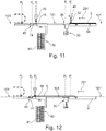
- the first elements 51' of the first handling unit 50 then retract the plate 5 longitudinally towards the loading surface 2 to a predetermined position (indicated by P* in figures 10 to 18 ) so as to allow the punching unit 30 to take the retracted configuration in a position below the reference plane 101 (see Figures 11 and 12 ). Having reached this position, the first elements 51' release the plate 5.
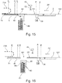
- control unit 300 sends a control signal to the second handling unit 45, then the handling elements 53 pick the plate 5 from the predetermined position P*, raising at least one front part 5B of the plate itself near the front edge 5' (condition in Figure 4 ).
- the control unit 300 then commands to the second handling unit 45 a longitudinal displacement (advancing toward the treatment station 7) of the transverse bar 46 until the holes 55 of the plate 5 reach the second longitudinal reference position P2 so that their axis is substantially aligned with the axis of the corresponding pin 15 of the bar 14 located in the housing station 40 (see diagram in Figure 7 ).
- the rear part of the plate 5 rests slipping on the reference plane 101.
- the control unit 300 then activates the pressing device 70 in order to provide the connection between the plate 5 and the bar 14 according to the principles and procedures set forth above.
- the control unit 300 commands to the second handling unit 45 a displacement to a neutral position, i.e. such as not to impede the movement in transversal direction 202 and the intervention of the pressing device 70.
- the control unit 300 also command the activation of the first handling elements 51' which intervene on the plate 5 temporarily blocking the movement in the longitudinal direction 201.
- the control unit 300 disables the first handling elements 51' and simultaneously sends a further control signal to the second handling unit 45, then the bar 46 and the handling elements 53 are moved so as to pick the bar 14, displacing longitudinally towards the treatment station 7 and finally releasing it at the defined third reference position P3 in the inlet section 71 of the treatment station 7.
- the elements 53 of the second handling unit 45 pick the pin bar 14 from a longitudinal housing position P4 which is more advanced than the second reference position P2. Following the release of the bar 14, the bar 45 of the second handling unit 45 is placed in a resting position, relatively remote from the treatment station 7.
- a dragging system 71 preferably comprises two electrically driven dragging chains 71A, each of which is installed on one side of the treatment station 7 (see Figure 2 ).
- Each chain 71A is integral in pin 73 which can be inserted, when said bar 14 is in said third reference position P3 in the cavity 16 defined by a corresponding end 14,14B of the pin bar 14. So, by means of such pins 73, the two chains 71A drag the bar 14 and the plate 5 connected thereto along the treatment station 7.
- the advancement of the plate 5 in the treatment station 7 is monitored by a position sensor.
- the control unit 300 commands the activation of the recharging device 80 in order to automatically load a pin bar 14 in the housing site 40.
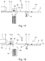
- the diagrams in Figures 16 to 18 show the sequence of movements implemented by the first displacement means 89' and by the second displacement means 89" defined above, which allow the lifting bar 88 and the gripping elements 89 to pick a pin bar 14 from the box 81 (see Figure 16 ) and release it into the housing site P4.
- this movement sequence requires a lowering of the lift bar 88 below the reference plane 101, a subsequent lifting above the plane 101 itself (see Figure 17 ), a forward movement to the housing position P4 and a successive release in this position (see Figure 18 ).
- Such a sequence is naturally determined by the position of the storage box 81 with respect to the housing site 40. A different relative position could lead to a different sequence of movements.
- the feeding assembly according to the invention allows to connect automatically a flexographic plate to a pin bar while loading, again automatically, said pin bar into a processing station of the plate.
- the feeding assembly according to the invention may be used to load a flexographic plate into the first station of an in-line treatment system but could also be used for feeding a totally autonomous treatment station.
Landscapes
- Physics & Mathematics (AREA)
- General Physics & Mathematics (AREA)
- Making Paper Articles (AREA)
Abstract
Description
- The present invention relates to the field of manufacturing digital printing plates for flexography. In particular, the present invention relates to a feeding assembly for automatically inserting a flexographic plate inside a treatment station which may be, for example, a washing station or an exposure station. The invention also relates to a system comprising at least one treatment station and at least one feeding assembly according to the present invention.
- Flexography is a direct rotary printing method which employs plates in relief made of photo-polymeric materials. The plates are flexible and soft, hence the name flexography. Such plates are inked and the print is obtained by means of direct deposition of the ink on the medium to be printed by virtue of a slight pressure exerted by a printing cylinder on which the plates are positioned.
- Flexography is a high-speed printing process, capable of printing on many types of absorbing and non-absorbing materials. Some typical applications of flexographic printing are the production of paper and plastic bags, milk cartons, disposable cups and the like, but by virtue of the progress in printing quality, flexography is today also used for printing newspapers, for example, as well as packets and labels and for printing on plastic, films and acetate sheets, packing paper and on many other materials used for product packaging.
- "Digital flexography" is a particular type of flexographic printing in which digital plates are used. In such plates, the photo-polymer is originally covered by a surface layer of material which prevents photo-exposure, such as for example a carbon or graphite layer. Such a layer of material is etched so as to create the negative image of the print subject. Such a step of etching is usually performed by means of a digital laser, controlled by a computer (hence the acronym CTP "Computer To Plate" used to indicate this step of the pre-printing process in the sector). The plate is then photo-exposed and the material not exposed to light is eliminated by washing with solvent or other liquid and then dried in an oven.
- Systems which allow the production of digital plates according to the principle described above are known. These systems provide the use of various treatment stations, among which a photo-exposure station and a washing station, in which the material not exposed to light is eliminated from the plate after photo-exposure. Normally, these systems also comprise an oven, operatively downstream of the washing station, to dry the plate. Downstream of the oven, an exposure station may be further provided in which the plates are exposed to UV-A, to allow the polymerization of the parts of the polymer, generally at minimum size details of the image to be printed, which were not removed by the brushes while washing, and/or are exposed to UV-C, to eliminate the "stickiness" of the polymer.
- On more recent versions, digital plate treatment systems extend substantially "in line". Patent application
EP 2839345 by the Applicant, for example, describes a system comprising a washing station in line with an exposure station and moving means which allow a continuous movement of the plate between the two treatment stations. Patent applicationWO 2016/030450 describes an in-line system conceptually similar to the one described inEP 2839345 , in which a drying station of the flexographic plates is provided downstream of the washing station. Such a system comprises automatic moving means which pick the plates let out from the washing station and store them in specific drying boxes. - On some systems, the photo-exposure of the plate is performed in an autonomous treatment station, i.e. separated from the rest of the system comprising the washing station and the drying station. In this regard, patent application
EP 3121653 describes an autonomous station for the photo-exposure of digital plates. In this case, at the end of the photo-exposure, the digital plate is picked and loaded into the washing station of the system. The latter may or may not be in line with the drying station. - On in-line systems, the plates are typically advanced through the treatment stations by using a pin bar to which the plate is coupled. Specifically, such a bar comprises a row of pins configured to be inserted into corresponding holes defined near a front edge of the plate, where the word "front" refers to the edge of the plate facing downstream with respect to a feeding direction of the plate. The pin bar is fed into the treatment station by means of a dragging system which is inside the station itself. More precisely, this system is configured to couple the opposite ends of the pin bar and to move it along said advancement direction. During such an advancement, the pin bar maintains an alignment direction transversal to the advancement direction by dragging the digital plate coupled thereto.
- In systems of this type, the connection between plate and pin bar always requires a manual intervention. In particular, an operator firstly proceeds by piercing a plurality of holes through the plate in which the pins of the bar can be inserted. A punching device, in nearly all cases separate from the rest of the system, is used for this purpose. Once the holes are defined through the plate, the operator proceeds by manually connecting the plate to the pin bar (by inserting the pins into corresponding holes) and positioning the pin bar in a predetermined position near the inlet of the treatment station. In such a position, the pin bar can be coupled and dragged, together with the plate, by the dragging system inside the treatment station.
- So, as a whole, the feeding of an in-line plant, and more in general of a treatment station, currently requires the manual intervention of an operator to load the plate, to connect the plate to the pin bar and finally to place the latter in the predetermined position for coupling it to the dragging system inside the first treatment station of the system. The need for a manual intervention is also found in systems in which the photo-exposure station is autonomous with respect to the in-line plant, in which the first treatment station is the washing station. In this case, the operator is required to perform a further intervention to physically transport the plate exiting from the exposure station to the punching device.
- It is apparent that the manual loading of the plates is a clearly critical aspect in terms of costs. In addition to this, manual operations, despite their apparent simplicity, are intrinsically accompanied by a certain degree of risk. Furthermore, all the steps required by the loading process (piercing holes, connecting the plate to the pin bar and positioning the pin bar) are entrusted solely to the attention and the skill of the operators. This aspect is clearly critical in terms of reliability.
- Given considerations above, it is the main task of the present invention to provide a feeding assembly for automatically loading a flexographic plate in a treatment station, which allows to overcome the drawbacks of the prior art. In the scope of this task, it is a first object of the present invention to provide a feeding assembly which allows the automatic connection, i.e. without the manual intervention of an operator, of a flexographic plate to a pin bar which can be dragged by a system inside the treatment station. It is another object of the present invention to provide a feeding assembly which allows a continuous loading, i.e. without interruptions and/or dead times. It is a not last object of the present invention to provide a feeding assembly which is reliable and easy to be manufactured at competitive costs.
- The present invention thus relates to a feeding assembly for automatically loading a flexographic plate in a treatment station. The assembly according to the invention is characterized in that it comprises:
- a loading surface, on which the flexographic plate is arranged, and an advancement surface, adjacent to said loading surface;
- handling means for moving the plate on said advancement surface between the loading surface and an inlet section of said treatment station, wherein the handling means define a longitudinal direction of displacement for the plate, a transversal direction orthogonal to the longitudinal direction and a vertical direction, orthogonal to the transversal direction and to the longitudinal direction;
- housing site in which a pin bar is arranged, wherein said housing site comprises a plurality of mutually aligned pins, such a bar is oriented so that said pins are aligned along the transversal direction;
- a punching unit comprising punching means which, in an activation configuration thereof, pierce a row of connecting holes through the plate.
- According to the invention, the handling means of the feeding assembly further comprise:
- a first handling unit of said plate which moves said plate along said longitudinal direction to take a front edge thereof to a first reference position at the reaching of which the punching means are activated to carry out a first row of holes near the front edge itself;
- a second handling unit which, following the carrying out of said holes, moves the plate along said longitudinal direction to a second reference position, at the reaching of which, said holes are aligned with corresponding pins of the pin bar. Furthermore, according to the invention, the feeding assembly comprises a pressing device for connecting the plate to the pin bar; such a pressing device applies a pressure on the plate as a result of which at least one pin of the bar is inserted in a corresponding hole of the plate and wherein following the connection between the plate and the bar, the second handling unit lifts the bar and moves it along said longitudinal direction to a third reference position in which said bar can be coupled to a dragging system of said treatment station.
- The feeding assembly according to the invention allows to connect automatically a flexographic plate to a pin bar while loading, again automatically, said pin bar into a treatment station of the plate. The feeding assembly according to the invention may be used to load a flexographic plate into the first station of an in-line treatment system but could be used for feeding a totally autonomous treatment station.
- Further features and advantages of the present invention will become more apparent from the following detailed description provided by way of non-limiting example and shown in the accompanying drawings, in which:
-
figure 1 is a diagrammatic view of a feeding assembly according to the present invention; -
figure 2 is a perspective view of a group of components of the feeding assembly according to the present invention; -
figure 3 is a perspective view of a handling unit of the feeding assembly according to the present invention; -
figures 4 and 5 are perspective views from different points of view of a group of components of a feeding assembly according to the present invention; -
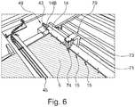
figure 6 is a perspective view of a pressing unit of the feeding assembly according to the present invention; -
figures 7 and 8 are diagrammatic views related to an operative step of a feeding assembly according to the present invention; - figures from 9 to 18 are diagrammatic views taken along the section line I-I in
Figure 1 related to operative steps of the feeding assembly according to the invention. - The same reference numbers and letters in the figures refer to the same elements or components.
- With reference to the aforesaid figures, the present invention thus relates to a feeding assembly 1 for automatically inserting/loading a
flexographic plate 5 in atreatment station 7 of the plate itself. In particular, the assembly 1 according to the invention is configured to connect, in automatic manner and without intervention by an operator, theplate 5 to apin bar 14 intended to be dragged through thetreatment station 7 by means of a dragging system. For the purposes of the present invention, the expression pin bar 14 (or more simply bar 14) indicates a body, preferably plate-shaped, which identifies a main direction ofdevelopment 105. Thebar 14 comprises a plurality ofpins 15 which emerge from a same side of the body and which are aligned along a direction parallel to themain direction 105. -
Figure 1 is a diagrammatic plan view of a treatment system of flexographic plates comprising an assembly 1 according to the invention. In particular, in this example, the assembly 1 is operatively interposed between afirst exposure station 6 and awashing station 7. The latter could be the first station of a system comprising several stations in line. It is worth noting that the assembly 1 according to the invention can also be used for loading plates in an in-line system in which the first station is an exposure station. Furthermore, in a further possible application, the assembly 1 can also be used to load a flexographic plate in an entirely autonomous treatment station (washing, exposure, drying), i.e. not in line with other stations. - The feeding assembly 1 comprises a
loading surface 2 on which theplate 5 is placed designed to be loaded in thetreatment station 7. Such a loading surface identifies a substantially horizontal reference plane 101'. Preferably, theplate 5 is automatically placed on theloading surface 2. For example, in the diagram ofFigure 1 , theexposure station 6 is arranged in a lateral position, vicinal to theloading surface 2 so that theplate 5, at theexposure station 6 outlet, lands directly onto theloading surface 2. In a possible constructional variant, the system could comprise two exposure stations arranged on opposite sides of theloading surface 2. - The feeding assembly 1 further comprises an advancement surface substantially defined between the
loading surface 2 and aninlet section 71 of thetreatment station 7 in which theplate 5 must be loaded. The expression "advancement surface" indicates a set of parts which define, as a whole, a substantiallyhorizontal reference plane 101, along which theplate 5 rests, either completely or partially, during its movement toward thetreatment station 7. Preferably, but not exclusively, the reference plane 101' defined by theloading surface 2 and thereference plane 101 are coplanar. - The assembly 1 according to the invention comprises handling means 45,50 of the
plate 5 configured to move theplate 5 between theloading surface 2 and theinlet section 71 of thetreatment station 7. In particular, the handling means 45,50 may intervene either directly or indirectly (through thebar 14 pins) on theplate 5 according to the principles set out below. As a whole, the movingmeans longitudinal direction 201 of displacement along which theplate 5 is moved. For the purposes of the present invention, the expression "transversal direction 202", instead, means a direction substantially orthogonal to thelongitudinal direction 201. Furthermore, the expression "vertical direction 203" means a direction orthogonal to the surface defined bydirections - The assembly 1 according to the invention comprises a
punching unit 30 comprising punching means 35 which, in an activation configuration thereof, pierce a row of connectingholes 55 through the plate 5 (seeFigure 7 ). In particular, the punching means 35 are configured to provideholes 55, the shape of which is such as to allow the insertion of apin 15 of saidrod 14 into each of them. The punchingunit 30 is located downstream of theloading surface 2, preferably in a position adjacent thereto. - The assembly 1 according to the invention further comprises a
housing site 40 in which thebar 14 is accommodated. More precisely, thebar 14 is oriented in a transversal direction, i.e. so that therespective pins 15 are aligned along the transversal direction 202 (orthogonal to the longitudinal direction 201). - According to the present invention, the handling means of the
plate 5 comprise afirst handling unit 50 which moves theplate 5 along thelongitudinal direction 201 to take a front edge 5' thereof to a first longitudinal reference position (indicated by P1) upon the reaching of which the punching means 35 are activated to carry out a row of connection holes 55 through the plate itself near said front edge 5'. - According to the present invention, the handling means of the
plate 5 also comprise asecond handling unit 45 to move theplate 5 following the formation of the connection holes 55. In particular, in a first operative step, thesecond handling unit 45 raises and moves theplate 5 along thelongitudinal direction 201 to a second reference longitudinal position (indicated by P2). In particular, said second position is such that the connection holes 55 are aligned with thepins 15 of thebar 14. In other words, thesecond handling unit 45 moves theplate 5 until an alignment position is reached such that the axis of eachhole 55 is substantially aligned with the axis of acorresponding pin 15. Upon reaching said second position P2, thesecond handling unit 45 releases theplate 5 preferably in such a condition that theplate 5 itself, at the connection holes 55, rests against thepins 15 of the pin bar 14 (preferred alignment condition). - The assembly 1 according to the invention comprises a
pressing device 70 which acts on theplate 5 to connect it to thebar 14. More precisely, thepressing device 70 presses theplate 5 near the connection holes so that eachpin 15 is inserted in a correspondinghole 55. According to a preferred embodiment, thepressing device 70 is configured to apply a thrust/localized pressure around eachhole 55, which in said second position P2, is precisely aligned with acorresponding pin 15. This localized pressure is such as to push the plate region about thehole 55 at the base of thecorresponding pin 15, thus ensuring its complete insertion in the respective hole and thus allowing the connection of theplate 5 to thehole 55, as a whole. According to a preferred embodiment, shown in the figures, thepressing device 70 is movable in thetransversal direction 202, so as to intervene in succession/sequence on each hole-pin pair. - According to an alternative embodiment, not shown in the figures, the
pressing device 70 may be shaped so as to act simultaneously on each pin-hole pair, i.e. so that all thepins 15 are inserted simultaneously into the corresponding holes 55. - In all cases, according to the present invention, once the connection of the
plate 5 to thebar 14 has been completed, and thus in a second operative step, thesecond handling unit 45 lifts the bar 14 (with which theplate 5 has become integral) and moves it to a third reference position P3 at which thepin bar 14 can be coupled with the dragging system 77 of thetreatment station 7. - According to that shown above, the
second handling unit 45 intervenes directly on theplate 5 in the first operative step, while it intervenes directly on thepin bar 14 in the second operative step. So, in this second operative step, thesecond handling unit 45 handles theplate 5 in an indirect manner precisely through thebar 14. - According to a preferred embodiment, the
second handling unit 45 raises a front portion 5a of theplate 5 near said front edge 5' in the first operative step. The second position P2 is such that each of theholes 55 takes a position substantially over a correspondingpin 15 of said pin bar 14 (seeFigure 7 ). When said second position P2 is reached, thesecond handling unit 45 translates the front portion 5a of theplate 5 downwards (i.e. lowered towards the advancement surface) so it rests on thepins 15 at theholes 55. In particular, thesecond handling unit 45 aligns theholes 55 with thepins 15 thus preparing the successive intervention of thepressing device 70. - According to a first aspect, the punching
units 30 preferably takes a retracted configuration and an emerging configuration with respect to thereference plane 101. In the retracted configuration (diagrammatically shown inFigure 9 ), the punchingunit 30 is substantially under thereference plane 101 so as not to hinder the movement of theplate 5 along thelongitudinal direction 201. In the emerging configuration (diagrammatically shown inFigure 10 ), the punching means 35 are located at a predetermined height with respect to thereference plane 101, upon the reaching of which they can carry outholes 55 through theplate 5. According to this preferred embodiment, the punchingunit 30 is substantially "retractable", meaning that disappears, when deactivated, below thereference plane 101. - Again according to a preferred embodiment, the punching
unit 30 comprises an upper plate 35' to which the punching means 35 are attached. The upper plate 35' defines a portion of the advancement surface when the punchingunit 30 takes the retracted configuration. For this purpose, the punching means 35 are fastened to the lower side of the upper plate 35'. As can be seen in the plan view infigure 1 , the upper plate 35' extends mainly along thetransversal direction 202 for a width (indicated by 301) preferably close to that of theloading surface 2. The upper plate 35' has a substantially rectangular shape, seen from the top. - In a preferred embodiment, the punching means 35 comprise a
body 36 which extends prevalently in thetransversal direction 202 for a length substantially close to thewidth 301 of the upper plate 35'. Such abody 36 defines acavity 37 facing theloading surface 2 into which a front portion 5A of saidplate 5 can be inserted, and preferably supported. More precisely, thebody 36 and thecavity 37 have a transversal extension such as to allow the front portion 5A to be inserted for the whole length thereof. - The punching means 35 comprise a plurality of punching
elements 38, each of which serves to carry out one of the connection holes 55. The punchingelements 38 are aligned along a direction parallel to thetransversal direction 202 and, in an activation configuration, move vertically with respect to thebody 36 so that their ends penetrate through theplate 5, whereby configuring the coupling holes 55 according to a principle can be easily inferred. - According to another aspect, the
cavity 37 of thebody 36 defines anabutment surface 39 for a front edge 5' of theplate 5. Such aabutment surface 39 extends parallel to thetransversal direction 202. Preferably, theabutment surface 39 establishes the first reference position P1 indicated above. Substantially, thefirst handling unit 50 moves theplate 5 until its front edge 5' comes into contact with theabutment surface 39. When such a condition is reached, the punching means 35 are activated so that the punchingelements 38 pierce the connection holes 55 through theplate 5. These will therefore be defined near the front edge 5' and aligned along thetransversal direction 202, parallel to the edge itself. - The punching
unit 30 comprises lifting means 34 (indicated inFigure 2 ) which raise and lower the upper plate 35', and more in general the punching means 35, with respect to thereference plane 101. In a possible embodiment, such lifting means may comprise electric actuators which act on the opposite ends of the upper plate 35' and/or on the opposite ends of thebody 36 of the punching means 35. Such lifting means 34 may be installed on the supportingframe 90 which supports the parts defining the advancement surface. - With reference again to
Figure 1 , thehousing site 40 is operatively positioned downstream of the punchingunit 30 and preferably in a position substantially adjacent to theinlet section 71 of thetreatment station 7. In a preferred embodiment, thehousing site 40 is defined by a supportingplate 41 supported by thesides 91 of theframe 90. As a whole, theframe 90 supports the advancement surface. Thepin bar 14 rests on theplate 41 with a side opposite to the one from which thepins 15 emerge. - The
housing site 40 comprises removable locking means which lock thebar 14 in a predetermined longitudinal position. In a possible embodiment shown inFigure 4 , the locking means comprise a pair of lockingmodules 49, each of which is installed on a side 8 of the supportingframe 90 to intervene on acorresponding end bar 14.Such modules 49 comprise anactuator 42 which moves a lockingpin 43 between a retracted position in which it does not interact with thebar 14, and an extended position. In the latter position, the lockingpin 43 is inserted in acavity 16 defined at anend bar 14 so as to lock the translation of the bar itself on the moving surface. In particular, the locking condition is maintained until the connection betweenplate 5 and bar 14 has been finally completed. Having reached this condition, the locking means are deactivated so as to allow thesecond handling unit 45 to move thepin bar 14 from thehousing site 40 up to the third reference position P3 in which it will be coupled by the dragging system 77 of thetreatment station 7. -
Figures 7 and 8 diagrammatically show in detail the step of connecting theplate 5 to thepin bar 14; according to that indicated above, such a connection is made at thehousing site 40 and following the displacement of theplate 5, made by thesecond handling unit 45, up to the second position P2. At the second position P2, eachhole 55 of theplate 5 takes a position substantially over a correspondingpin 15 of thebar 14, i.e. the axis of eachhole 55 is substantially aligned with the axis of thecorresponding pin 15. The connection betweenplate 5 and pins 15 is obtained by activating thepressing device 70. - As indicated above, the
pressing device 70 is preferably configured to apply a localized pressure on theplate 5 about the edge of ahole 55 aligned with acorresponding pin 15. In particular, thepressing device 70 is configured to apply a pressure which is such as to locally push theplate 5 at the base of said correspondingpin 15, whereby guaranteeing full insertion in the correspondinghole 55. Preferably, thepressing device 70 is structurally independent from thesecond handling unit 45 and is movable in thetransversal direction 202 to intervene at each pair hole-pin, the word "pair" indicating ahole 55 and thecorresponding pin 15. - In the embodiment shown in
figures 5 ,6 and8 , thepressing unit 70 preferably comprises an actuator 71 (either electric or pneumatic) mounted by means of a supportingarm 73 on aslide 72 movable along thetransversal direction 202. Such anactuator 71 vertically moves apresser 74 comprising acylindrical end 74A which defines acavity 75 in which thehead 15A of apin 15 of thebar 14 can be inserted. In particular, theactuator 71 moves thepresser 74 vertically (arrow 404) between a raised non-intervention position and a lowered intervention position. Considering a hole-pin pair, in reaching the lowered position, thehead 15A of thepin 15 is inserted into the cavity of thepresser 74, while the edge of thecylindrical end 74A locally pushes the portion ofplate 5 about thehole 55 to the base of thepin 15. Once thepresser device 70 has treated all the hole-pin pairs in sequence, theplate 5 is constrained in a stable manner to thepin bar 14. - Preferably, one of the
sides 91 of the supportingframe 90 defines a receivinghousing 95 in which thepressing device 70 remains housed during the longitudinal movement of theplate 5 and/or of the bar 14 (seeFigure 5 ). In particular, thepressing device 70 is preferably actuated when thesecond handling unit 45 has released theplate 5. In this condition, thepressing device 70 moves transversely to a first transversal position corresponding to the first hole-pin pair. Having reached such a first position, thepressing element 74 is lowered by theactuator 71 to complete the connection. As can be inferred from the diagram inFigure 8 , thepressing device 70 is displaced intransversal direction 202 whereby processing each hole-pin pair. Once the operation has been completed, thepressing device 70 returns into the receivinghousing 95 so as not to hinder the subsequent translation of thebar 14 and of theplate 5 towards thetreatment station 7. - Preferably, before the activation of the
pressing device 70, thefirst handling unit 50 is activated again to temporarily lock theplate 5 in the second position P2. The activation of thefirst handling unit 50 has the purpose of preventing any movement of theplate 5 on the movement surface during the subsequent intervention of thepressing device 70. As soon as the latter has completed the connection of theplate 5 to thebar 14, thefirst handling unit 50 is deactivated to allow the successive movement, achieved by thesecond handling unit 45, of theplate 5 in the third reference position P3 indicated above. - Preferably, the
first handling unit 50 comprises first handling elements 51' configured to intervene on theplate 5 and to adjust its position along thelongitudinal direction 201. In a preferred but not exclusive embodiment, such first elements 51' are operatively placed in a position below the reference plane 101' defined by theloading surface 2 in order to act on thelower surface 5E of theplate 5. More precisely, the first elements 51' are vertically movable between a non-intervention position, in which they are below the reference plane 101', and an intervention position, in which they act on saidlower surface 5E. Further, the first elements 51' are movable also in parallel to thelongitudinal direction 201 so as to adjust the position of theplate 5 along the same direction. - Preferably, said first elements 51' are of the suction cup type, i.e. comprise a body provided with a suction cup end susceptible of attaching itself to said
lower surface 5E, following the application of vacuum between the suction cup body and the surface, according to a principle known per se. - The
first handling unit 50 further comprises first adjusting means 58A in thelongitudinal direction 201 and second adjustment means 59A in avertical direction 201 to achieve the movements of the first elements 51' in the corresponding direction. The adjustment means 58A may consist of electric actuators, mounted on slides. The second adjustment means 59A may, in turn, be constituted by additional electric actuators operatively connected to said slides. - In a possible embodiment shown in
Figure 1 , theloading surface 2 defines first grooves 58' through which the first suction cup elements 51' emerge to adhere against thelower surface 5E of theplate 5. Suchfirst grooves 58 extend in thelongitudinal direction 201 - In a first possible embodiment, the first longitudinal actuating means 58A move the first handling elements 51' so that they take the same position along the
longitudinal direction 201. Therefore, as a whole, the first elements means 51' form only a longitudinal translation of theplate 5. - In an alternative embodiment, the first adjustment means 58A may move the first handling elements 51' independently, i.e. allowing them to take different longitudinal positions. This translates into the possibility of imposing a translational motion to the
plate 5 in the longitudinal direction, but also a roto-translational movement designed to correct the orientation of theplate 5 itself. In particular, the purpose of such a correction would be to orient the front edge 5' parallel to thetransversal direction 202. - According to the above, when the second position P2 is reached and before actuating the
pressing device 70, the first handling elements 51' are preferably activated to lock theplate 5, whereby avoiding any translation thereof inlongitudinal direction 201. Once thepressing device 70 has completed the connection between theplate 5 and thebar 14, the first elements 51' are deactivated to allow the subsequent longitudinal displacement of theplate 5. - With reference again to
Figure 1 , thefirst handling unit 50 preferably also comprisessecond handling elements 51" configured to act on theplate 5 and to adjust its position along thetransversal direction 202. Preferably, thesecond elements 51" have a configuration similar to that of the first elements 51'. So, also thesecond elements 51" are preferably of the suction cup type. Thesecond elements 51" are movable in avertical direction 203 and intransversal direction 202. Therefore, the handling unit will comprise further adjustment means in vertical direction (not shown) and adjusting means in transversal direction (not shown). The configuration of the adjustment means of thesecond handling elements 51" may substantially correspond to that described for the first elements 51'. - As shown with respect to the first elements 51', also the
second elements 51" are preferably located in a position below the reference plane 101' defined by theloading surface 2. Preferably, the latter definessecond grooves 58" which extend in transversal direction to allow the secondsuction cup elements 51" to stick to thebottom surface 5E of theplate 5 and to move along thetransversal direction 202. Said adjustment means intransversal direction 202 may be configured to move thesecond elements 51" so that they take the same transversal position. Alternatively, said adjustment means in transversal direction can provide an independent adjustment of thesecond elements 51", so as to introduce a roto-translation movement adapted to facilitate the orientation of theplate 5. - According to another aspect of the present invention, the
second handling unit 45 preferably comprises atransversal bar 46, the position of which can be adjusted along thevertical direction 203 and along thelongitudinal direction 201. Therefore, thetransversal bar 46 has two degrees of freedom and supports a plurality of handlingelements 53, preferably of the suction cup type, aligned along a direction parallel to thetransversal direction 202. According to the objects of the present invention, thehandling elements 53 are configured to raise and support theplate 5 during the movement up to the second reference position P2 and to raise and support thebar 14, and thus theplate 5, until they reach a third reference position P3 in which thebar 14 is released. -
Figure 3 shows a possible embodiment of thesecond handling unit 45 and in particular of thebar 46 which emerges with respect to thereference plane 101. In order to allow the movement of thetransversal bar 46 along the two directions (longitudinal 201, vertical 203) indicated above, thesecond handling unit 45 comprises first actuation means and second actuation means for respectively moving the transversal bar along thevertical direction 203 and along thelongitudinal direction 201. In an embodiment shown inFigures 2 and 3 , the first actuation means comprise a pair ofactuators 66, each of which is connected to one end of the transversal bar 460. The twoactuators 66 are fixed to a supportingbar 47 over the transversal bar 60. The supporting bar 61 maintains the same height relative to theadvancement surface 3, while the twoactuators 66 lift and lower thetransversal bar 46. For this purpose, each of the ends of the supporting bar 61 is mounted on acorresponding slide 69 which can slide along aguide 64 connected to aside 91 of the supportingframe 90. The second actuating means comprise adrive chain 62 for eachslide 69, preferably actuated by an electric motor, which is connected to acorresponding slide 69 to drag it inlongitudinal direction 201. It is within the scope of the present invention the possibility of providing the second handling unit in a constructionally different but functionally equivalent manner with respect to that described above. - According to a further aspect, the feeding assembly 1 according to the invention preferably also comprises a
recharging device 80 to automatically position apin bar 14 in thehousing site 40 defined above. With reference to the diagrammatic views from 9 to 18, therecharging device 80 comprises astorage box 81 in which a plurality of pin bars 14 are housed. Such abox 81 is preferably located in a position below thereference plane 101. Therecharging device 80 comprises gripping and movingmeans bar 14 accommodated in thebox 81 and release it at thehousing site 40 defined above. - In a preferred embodiment, the gripping and moving means comprise a
lift bar 88 which, in a non-activation condition of therecharging device 80, defines a portion of the reference plane 101 (seefigure 1 ), preferably between thehousing site 40 and the punchingunit 30. The gripping and handling means comprisegripping elements 89, preferably of suction cup type, which emerge from the lower side of the liftingbar 88, whereby being aligned in thetransversal direction 202. In this preferred embodiment, thebox 81 configures a volume in which a plurality of superimposed and oriented pin bars 14 are housed in thetransversal direction 202. Preferably, thebox 81 is extracted and inserted below thereference plane 101 through a movement intransversal direction 202. This translation allows to reload thebox 81 with a series of pin bars 14. - The lifting
bar 88 is movable in the vertical direction and in the longitudinal direction so as to form a sequence of movements (vertical and longitudinal) such as to allow the picking of abar 14 from thebox 81 and the successive release thereof at thehousing site 40. In the embodiment shown in the figures, the longitudinal position in which thebar 14 is picked from thebox 81 is different (and more retracted than the advancement direction 201) from the longitudinal position in which thepin bar 14 itself is released (at the housing site 40). However, the two longitudinal positions indicated above may also coincide; for example, thebox 81 may be located under thehousing site 40. - In order to allow the movement of the
bar 14 to thehousing site 40, therecharging device 80 further comprises further first displacement means 89' and second displacement means 89" to achieve the vertical movements (direction 203) and longitudinal movements (direction 201) of thebar 14, respectively. Such displacement means 89',89" may consist of actuators and longitudinal handling slides, similarly to the technical solutions described above for the handlingunits plate 5. - With reference to the aforesaid figures and particularly to
Figures 9 to 18 , the operating principle of the feeding assembly 1 according to the present invention schematically shown inFigure 1 , which is a preferred but not exclusive embodiment, is illustrated below. In this regard, the feeding assembly 1 comprises a control unit 300 (shown inFigure 9 ) for controlling the handling means of the punching units, and in general of all the aforementioned of the assembly 1 according to the invention. - The
plate 5 exits from theexposure station 6 intransversal direction 202. When a portion of theplate 5 rests on theloading surface 2, thesecond handling elements 51" intervene on such a portion, whereby guiding theplate 5 intransversal direction 202 until it rests completely on theloading surface 2 and a longitudinal edge thereof aligns with a transversal reference (indicated byline 401 inFigure 1 ). When this condition is achieved, detected by a position sensor, thecontrol unit 300 commands the activation of the punchingunit 30, which takes the emerging configuration (seeFigure 10 ) with respect to thereference plane 101 so that the punching means 35 take a position adapted to provide theholes 55 cross theplate 5. Subsequently, thecontrol unit 300 sends a first control signal to the first handling elements 51', then they intervene on theplate 5 moving it inlongitudinal direction 201 until its front edge 5' comes into contact with theabutment surface 39 of thebody 36 of the punching means 35 (first reference position P1). Having reached this condition, thecontrol unit 300 activates the punching means 35 so that they pierce the row ofholes 55 through theplate 5 near said front edge 5'. The first elements 51' of thefirst handling unit 50 then retract theplate 5 longitudinally towards theloading surface 2 to a predetermined position (indicated by P* infigures 10 to 18 ) so as to allow thepunching unit 30 to take the retracted configuration in a position below the reference plane 101 (seeFigures 11 and 12 ). Having reached this position, the first elements 51' release theplate 5. - At this point, the
control unit 300 sends a control signal to thesecond handling unit 45, then thehandling elements 53 pick theplate 5 from the predetermined position P*, raising at least onefront part 5B of the plate itself near the front edge 5' (condition inFigure 4 ). Thecontrol unit 300 then commands to the second handling unit 45 a longitudinal displacement (advancing toward the treatment station 7) of thetransverse bar 46 until theholes 55 of theplate 5 reach the second longitudinal reference position P2 so that their axis is substantially aligned with the axis of thecorresponding pin 15 of thebar 14 located in the housing station 40 (see diagram inFigure 7 ). In the advancement between the retracted position P* and the second position P2, the rear part of theplate 5 rests slipping on thereference plane 101. - The
control unit 300 then activates thepressing device 70 in order to provide the connection between theplate 5 and thebar 14 according to the principles and procedures set forth above. Before the intervention of thepressing device 70, thecontrol unit 300 commands to the second handling unit 45 a displacement to a neutral position, i.e. such as not to impede the movement intransversal direction 202 and the intervention of thepressing device 70. At the same time, thecontrol unit 300 also command the activation of the first handling elements 51' which intervene on theplate 5 temporarily blocking the movement in thelongitudinal direction 201. - With reference to
Figures 13 and 14 , at the end of the intervention of thepressing device 70, thecontrol unit 300 disables the first handling elements 51' and simultaneously sends a further control signal to thesecond handling unit 45, then thebar 46 and thehandling elements 53 are moved so as to pick thebar 14, displacing longitudinally towards thetreatment station 7 and finally releasing it at the defined third reference position P3 in theinlet section 71 of thetreatment station 7. Theelements 53 of thesecond handling unit 45 pick thepin bar 14 from a longitudinal housing position P4 which is more advanced than the second reference position P2. Following the release of thebar 14, thebar 45 of thesecond handling unit 45 is placed in a resting position, relatively remote from thetreatment station 7. - With reference to
Figure 15 , once released in the third reference position P3, thepin bar 14 is coupled by the draggingsystem 71 of thetreatment station 7 and dragged inside the station itself. In this regard, such adragging system 71 preferably comprises two electrically driven draggingchains 71A, each of which is installed on one side of the treatment station 7 (seeFigure 2 ). Eachchain 71A is integral inpin 73 which can be inserted, when saidbar 14 is in said third reference position P3 in thecavity 16 defined by acorresponding end pin bar 14. So, by means ofsuch pins 73, the twochains 71A drag thebar 14 and theplate 5 connected thereto along thetreatment station 7. - The advancement of the
plate 5 in thetreatment station 7 is monitored by a position sensor. When theplate 5 is completely inside thetreatment station 7, thecontrol unit 300 commands the activation of therecharging device 80 in order to automatically load apin bar 14 in thehousing site 40. The diagrams inFigures 16 to 18 show the sequence of movements implemented by the first displacement means 89' and by the second displacement means 89" defined above, which allow the liftingbar 88 and thegripping elements 89 to pick apin bar 14 from the box 81 (seeFigure 16 ) and release it into the housing site P4. As apparent, this movement sequence requires a lowering of thelift bar 88 below thereference plane 101, a subsequent lifting above theplane 101 itself (seeFigure 17 ), a forward movement to the housing position P4 and a successive release in this position (seeFigure 18 ). Such a sequence is naturally determined by the position of thestorage box 81 with respect to thehousing site 40. A different relative position could lead to a different sequence of movements. - The described technical solutions allow to fully achieve the predetermined tasks and objects. In particular, the feeding assembly according to the invention allows to connect automatically a flexographic plate to a pin bar while loading, again automatically, said pin bar into a processing station of the plate. The feeding assembly according to the invention may be used to load a flexographic plate into the first station of an in-line treatment system but could also be used for feeding a totally autonomous treatment station.
Claims (10)
- A feeding assembly (1) for loading a flexographic plate (5) in a treatment station (7), characterized in that it comprises:- a loading surface (2), on which said plate (5) is arranged, and an advancement surface (101), adjacent to said loading surface (2);- handling means (45,50) for moving said plate (5) on said advancement surface (3) between said loading surface (2) and an inlet section (71) of said treatment station (7), wherein said handling means define a longitudinal direction (201) of displacement for said plate (5), a transversal direction (202) orthogonal to said longitudinal direction (201) and a vertical direction (203);- a housing site (40) in which a pin bar (14) is arranged, which comprises a plurality of mutually aligned pins (15), wherein said bar (14) is oriented so that said pins (15) are aligned along a direction parallel to said transversal direction (202);- a punching unit (30) comprising punching means (35) which, in an activation configuration thereof, carry out a row of connecting holes (55) through said plate (5) andwherein said handling means comprise:- a first handling unit (50) of said plate (5) which moves said plate (5) along said longitudinal direction (201) to take a front edge (5') thereof to a first reference position (P1) at the reaching of which, said punching means (35) make said connecting holes (55) near said front edge (5');a second handling unit (45) which, following the carrying out of said holes (55), moves the plate (5) along said longitudinal direction (201) to a second reference position (P2), at the reaching of which, said holes (55) are aligned with corresponding pins (15) of said pin bar (14), and
wherein said assembly (1) comprises a pressing device (70) for connecting said plate (5) to said pin bar (14), said pressing device (70) applying a pressure on said plate (5) as a result of which at least one pin (15) of said bar (14) is inserted in a corresponding hole (55) of said plate (5) and wherein, following the connection between said plate (5) and said bar (14), said second handling unit (45) lifts said bar (14) and moves it along said longitudinal direction (201) to a third reference position (P3) in which said bar (14) is couplable to a dragging system of said treatment station (7). - An assembly (1) according to claim 1, wherein said punching unit (30) preferably assumes a retracted configuration and an emerging configuration with respect to said advancement surface (101) and wherein in said retracted configuration said punching unit (30) is substantially underneath said advancement surface (101).
- An assembly (1) according to claim 2, wherein said punching unit (30) comprises an upper plate (35'), which defines a portion of said advancement surface (101) when said punching unit (30) assumes said retracted configuration, said punching means (35) being constrained to the lower side of said upper plate (35').
- An assembly (1) according to claim 2 or 3, wherein said punching means (35) comprise a body (36), which extends prevalently along said transversal direction (202), said body (36) defining a cavity (37) facing towards said loading surface (2) and in which a front portion (5A) of said plate (5) can be inserted, and wherein said punching means (35) comprise a plurality of punching elements (38), each of which to make one of said connecting holes (55), and wherein said cavity (37) of said body (36) defines an abutment surface (39) for said front edge (5A) of the plate (5).
- An assembly (1) according to any one of the preceding claims from 1 to 4, wherein said housing site (40) comprises locking/releasing means which lock/release said pin bar (14) in a predetermined longitudinal position.
- An assembly (1) according to claim 5, wherein said locking means comprise a pair of locking modules (49), each of which is installed near a side (91) of a supporting frame (90), each of said modules (49) comprising an actuator (42) which moves a locking pin (43) between a retracted position, in which said locking pin (43) does not interact with said bar (14), and an extended position, in which said pin (43) is inserted in a cavity (16) defined in a corresponding end (14A, 14B) of said bar (14).
- An assembly (1) according to any one of the preceding claims from 1 to 6, wherein said pressing unit (70) comprises an actuator (71) mounted on a slide (72) movable along said transversal direction (202), said actuator (71) vertically moving a presser (74) comprising a cylindrical end (74A) defining a cavity (75) in which the head (15A) of a pin (15) of said bar (14) can be inserted, and wherein said actuator (71) moves said presser (74) between a lifted non-engagement position and a lowered engagement position, and wherein when reaching said lowered position of said head (15A) said cylindrical end (74A) of said presser (74) locally pushes, towards the base of said pin (15), said region of said plate (5) about the hole (55), while said head (14A) of said pin (15) is inserted in said cylindrical end (74A) of said presser (74).
- An assembly (1) according to any one of the preceding claims from 1 to 7, wherein said assembly (1) comprises a recharging device (80) for positioning a pin bar (14) in said housing site (40), said device (80) comprising at least one storage box (81) and gripping and moving means (88,89), which, when activated, pick a pin bar (14) from said box (81) and release it in said housing site (40).
- An assembly (1) according to claim 8, wherein said gripping and moving means comprise a lifting bar (88) which supports gripping elements (89) aligned along said transversal direction (202), said lifting bar (88) being movable along said longitudinal direction (201) and along said vertical direction (203).
- A system for treating flexographic plates comprising at least one treatment station of a flexographic plate and comprising a feeding assembly (1) according to any one of the claims from 1 to 9 to load a flexographic plate automatically in said at least one treatment station.
Applications Claiming Priority (1)
| Application Number | Priority Date | Filing Date | Title |
|---|---|---|---|
| IT102017000051285A IT201700051285A1 (en) | 2017-05-11 | 2017-05-11 | POWER SUPPLY UNIT FOR AUTOMATIC LOADING OF A FLEXOGRAPHIC SLAB IN A TREATMENT STATION |
Publications (2)
| Publication Number | Publication Date |
|---|---|
| EP3401734A1 true EP3401734A1 (en) | 2018-11-14 |
| EP3401734B1 EP3401734B1 (en) | 2022-04-20 |
Family
ID=60020322
Family Applications (1)
| Application Number | Title | Priority Date | Filing Date |
|---|---|---|---|
| EP18171690.3A Active EP3401734B1 (en) | 2017-05-11 | 2018-05-10 | Feeding assembly for loading a flexographic plate in a treatment station |
Country Status (4)
| Country | Link |
|---|---|
| US (1) | US10678136B2 (en) |
| EP (1) | EP3401734B1 (en) |
| ES (1) | ES2914300T3 (en) |
| IT (1) | IT201700051285A1 (en) |
Cited By (4)
| Publication number | Priority date | Publication date | Assignee | Title |
|---|---|---|---|---|
| NL2023988B1 (en) * | 2019-10-10 | 2021-04-15 | Xeikon Prepress Nv | Punching Station and Method for a Relief plate precursor |
| WO2022144291A1 (en) * | 2020-12-30 | 2022-07-07 | Esko-Graphics Imaging Gmbh | Process and apparatus for feeding a flexographic printing plate processor |
| CN116601004A (en) * | 2020-12-17 | 2023-08-15 | 阿合斯印前有限公司 | Apparatus and method for operating a panel |
| IT202300017103A1 (en) | 2023-08-10 | 2025-02-10 | Vianord Eng Sasu | METHOD FOR ALIGNMENT AND PUNCHING A FLEXOGRAPHIC PLATE AND GROUP FOR IMPLEMENTING THIS METHOD |
Families Citing this family (1)
| Publication number | Priority date | Publication date | Assignee | Title |
|---|---|---|---|---|
| US11953834B2 (en) * | 2018-04-26 | 2024-04-09 | Xsys Prepress N.V. | Apparatus and method for treating and transporting a relief printing plate precursor |
Citations (6)
| Publication number | Priority date | Publication date | Assignee | Title |
|---|---|---|---|---|
| DE4231103A1 (en) * | 1992-09-17 | 1994-03-24 | Du Pont Deutschland | Flexographic printing plate movement - gives movement to leading end of plate to secure and release it to carrier bar at processing station for simplified and automated working |
| US5684571A (en) * | 1995-06-05 | 1997-11-04 | Western Litho Plate & Supply Co. | Apparatus for and method of exposing photosensitized plates |
| US20090013888A1 (en) * | 2006-02-14 | 2009-01-15 | Dantex Graphics Ltd. | Methods and Means Relating to Photopolymer Printing Plates |
| EP2839345A1 (en) | 2012-04-19 | 2015-02-25 | Sasu Vianord Engineering | Method and apparatus for the photopolymerization and the washing in series of digital printing plates for flexography |
| CA2958912A1 (en) * | 2014-08-28 | 2016-03-03 | Flint Group Germany Gmbh | Apparatus and method for producing flexographic printing plates |
| EP3121653A1 (en) | 2015-05-20 | 2017-01-25 | Sasu Vianord Engineering | Apparatus and method for the photo-polymerization of flexographic digital printing plates |
Family Cites Families (1)
| Publication number | Priority date | Publication date | Assignee | Title |
|---|---|---|---|---|
| DE4231102C2 (en) * | 1992-09-17 | 1998-07-02 | Du Pont Deutschland | Process for the production of photopolymerizable flexographic printing plates |
-
2017
- 2017-05-11 IT IT102017000051285A patent/IT201700051285A1/en unknown
-
2018
- 2018-05-09 US US15/975,513 patent/US10678136B2/en active Active
- 2018-05-10 ES ES18171690T patent/ES2914300T3/en active Active
- 2018-05-10 EP EP18171690.3A patent/EP3401734B1/en active Active
Patent Citations (7)
| Publication number | Priority date | Publication date | Assignee | Title |
|---|---|---|---|---|
| DE4231103A1 (en) * | 1992-09-17 | 1994-03-24 | Du Pont Deutschland | Flexographic printing plate movement - gives movement to leading end of plate to secure and release it to carrier bar at processing station for simplified and automated working |
| US5684571A (en) * | 1995-06-05 | 1997-11-04 | Western Litho Plate & Supply Co. | Apparatus for and method of exposing photosensitized plates |
| US20090013888A1 (en) * | 2006-02-14 | 2009-01-15 | Dantex Graphics Ltd. | Methods and Means Relating to Photopolymer Printing Plates |
| EP2839345A1 (en) | 2012-04-19 | 2015-02-25 | Sasu Vianord Engineering | Method and apparatus for the photopolymerization and the washing in series of digital printing plates for flexography |
| CA2958912A1 (en) * | 2014-08-28 | 2016-03-03 | Flint Group Germany Gmbh | Apparatus and method for producing flexographic printing plates |
| WO2016030450A1 (en) | 2014-08-28 | 2016-03-03 | Flint Group Germany Gmbh | Apparatus and method for producing flexographic printing plates |
| EP3121653A1 (en) | 2015-05-20 | 2017-01-25 | Sasu Vianord Engineering | Apparatus and method for the photo-polymerization of flexographic digital printing plates |
Cited By (13)
| Publication number | Priority date | Publication date | Assignee | Title |
|---|---|---|---|---|
| EP4041507B1 (en) | 2019-10-10 | 2023-05-31 | Xsys Prepress N.V. | Punching station and method for a relief plate precursor |
| WO2021069540A1 (en) * | 2019-10-10 | 2021-04-15 | Xeikon Prepress N.V. | Punching station and method for a relief plate precursor |
| CN114728432A (en) * | 2019-10-10 | 2022-07-08 | 赛康印前公众有限公司 | Punching station and punching method for a relief precursor |
| US20220339812A1 (en) * | 2019-10-10 | 2022-10-27 | Xeikon Prepress N.V. | Punching station and method for a relief plate precursor |
| JP2022551287A (en) * | 2019-10-10 | 2022-12-08 | エクシス プリプレス エヌ.ブイ. | Stamping station and method for relief plate precursor |
| NL2023988B1 (en) * | 2019-10-10 | 2021-04-15 | Xeikon Prepress Nv | Punching Station and Method for a Relief plate precursor |
| CN114728432B (en) * | 2019-10-10 | 2024-07-23 | 阿合斯印前有限公司 | Punching station and punching method for relief printing precursor |
| US12583142B2 (en) * | 2019-10-10 | 2026-03-24 | Xsys Prepress N.V. | Punching station and method for a relief plate precursor |
| CN116601004A (en) * | 2020-12-17 | 2023-08-15 | 阿合斯印前有限公司 | Apparatus and method for operating a panel |
| WO2022144291A1 (en) * | 2020-12-30 | 2022-07-07 | Esko-Graphics Imaging Gmbh | Process and apparatus for feeding a flexographic printing plate processor |
| US20240118623A1 (en) * | 2020-12-30 | 2024-04-11 | Esko-Graphics Imaging Gmbh | Process and apparatus for feeding a flexographic printing plate processor |
| US12455506B2 (en) * | 2020-12-30 | 2025-10-28 | Esko-Graphics Imaging Gmbh | Process and apparatus for feeding a flexographic printing plate processor |
| IT202300017103A1 (en) | 2023-08-10 | 2025-02-10 | Vianord Eng Sasu | METHOD FOR ALIGNMENT AND PUNCHING A FLEXOGRAPHIC PLATE AND GROUP FOR IMPLEMENTING THIS METHOD |
Also Published As
| Publication number | Publication date |
|---|---|
| EP3401734B1 (en) | 2022-04-20 |
| ES2914300T3 (en) | 2022-06-09 |
| US10678136B2 (en) | 2020-06-09 |
| IT201700051285A1 (en) | 2018-11-11 |
| US20180329303A1 (en) | 2018-11-15 |
Similar Documents
| Publication | Publication Date | Title |
|---|---|---|
| EP3401734B1 (en) | Feeding assembly for loading a flexographic plate in a treatment station | |
| CN107710905B (en) | Belt cutting processing device and processing method | |
| US5169284A (en) | Grasping and transfer claw | |
| AT503572B1 (en) | Conveyance apparatus for depalletizing goods stacked on support, has conveyance device formed by movable receiving conveyor forming placement plane | |
| FI84463B (en) | FOERFARANDE OCH ANORDNING FOER PLOCKNING OCH HANTERING AV LAPPAR SPECIELLT AV POROEST OCH BOEJLIGT MATERIAL. | |
| NL8102679A (en) | DEVICE FOR MOUNTING "CHIP" CHAIN ELEMENTS ON WIRED CARDS. | |
| JP7163488B2 (en) | Vacuum gripper, supply unit and method of transferring planar components | |
| JP6532682B2 (en) | Package unpacking processor | |
| KR101563443B1 (en) | Hot-stamping printing device | |
| US4657466A (en) | Apparatus for moving strips using mechanical manipulator | |
| KR101336573B1 (en) | Auto printing equipment for packing | |
| US4950128A (en) | Automatic loading unit for sheet units onto machines equipped with a conveyor | |
| JP2002001906A (en) | Clothes loading device and method of loading clothes on screen printing pallet | |
| EP3103745B1 (en) | Method and machine for discharging a roll of tape from a winding spindle | |
| US5052876A (en) | Unpackaging apparatus for packaged sheets | |
| KR102116625B1 (en) | A gripping device for holding the insert seats, a loading device, a station for receiving blanks and a mechanical device for processing elements in the form of seats | |
| KR101597179B1 (en) | Apparatus for Attaching Subsidiary Materials | |
| DE102019105495B4 (en) | Removal device for the automated removal of fabric material parts, a method for the automated removal of fabric material parts and a production plant with a conveyor device and a removal device | |
| DE2742159C3 (en) | Device for removing a package of sheet material from a default stack and feeding the package to a vibrating table inclined to the horizontal | |
| KR102309796B1 (en) | Mask loading apparatus | |
| KR101058151B1 (en) | Silk screen printer | |
| CN115339718A (en) | Loading and unloading device and code pasting equipment | |
| EP4392355B1 (en) | Hide feeding apparatus in lines for the treatment or working of hides | |
| ITMI20060912A1 (en) | PLANT FOR THE TREATMENT OF MATERIALS IN SHEET WITH AUTOMATIC MEANS OF FEEDING-UNLOADING THE SHEETS | |
| US12251822B2 (en) | Method for controlling a gripper |
Legal Events
| Date | Code | Title | Description |
|---|---|---|---|
| PUAI | Public reference made under article 153(3) epc to a published international application that has entered the european phase |
Free format text: ORIGINAL CODE: 0009012 |
|
| STAA | Information on the status of an ep patent application or granted ep patent |
Free format text: STATUS: THE APPLICATION HAS BEEN PUBLISHED |
|
| AK | Designated contracting states |
Kind code of ref document: A1 Designated state(s): AL AT BE BG CH CY CZ DE DK EE ES FI FR GB GR HR HU IE IS IT LI LT LU LV MC MK MT NL NO PL PT RO RS SE SI SK SM TR |
|
| AX | Request for extension of the european patent |
Extension state: BA ME |
|
| STAA | Information on the status of an ep patent application or granted ep patent |
Free format text: STATUS: REQUEST FOR EXAMINATION WAS MADE |
|
| RBV | Designated contracting states (corrected) |
Designated state(s): AL AT BE BG CH CY CZ DE DK EE ES FI FR GB GR HR HU IE IS IT LI LT LU LV MC MK MT NL NO PL PT RO RS SE SI SK SM TR |
|
| 17P | Request for examination filed |
Effective date: 20190514 |
|
| RIC1 | Information provided on ipc code assigned before grant |
Ipc: G03F 7/30 20060101AFI20210707BHEP Ipc: B41F 27/14 20060101ALI20210707BHEP |
|
| GRAP | Despatch of communication of intention to grant a patent |
Free format text: ORIGINAL CODE: EPIDOSNIGR1 |
|
| STAA | Information on the status of an ep patent application or granted ep patent |
Free format text: STATUS: GRANT OF PATENT IS INTENDED |
|
| INTG | Intention to grant announced |
Effective date: 20210819 |
|
| RIN1 | Information on inventor provided before grant (corrected) |
Inventor name: DE CARIA, RICCARDO |
|
| GRAJ | Information related to disapproval of communication of intention to grant by the applicant or resumption of examination proceedings by the epo deleted |
Free format text: ORIGINAL CODE: EPIDOSDIGR1 |
|
| STAA | Information on the status of an ep patent application or granted ep patent |
Free format text: STATUS: REQUEST FOR EXAMINATION WAS MADE |
|
| INTC | Intention to grant announced (deleted) | ||
| GRAP | Despatch of communication of intention to grant a patent |
Free format text: ORIGINAL CODE: EPIDOSNIGR1 |
|
| STAA | Information on the status of an ep patent application or granted ep patent |
Free format text: STATUS: GRANT OF PATENT IS INTENDED |
|
| INTG | Intention to grant announced |
Effective date: 20220121 |
|
| GRAS | Grant fee paid |
Free format text: ORIGINAL CODE: EPIDOSNIGR3 |
|
| GRAA | (expected) grant |
Free format text: ORIGINAL CODE: 0009210 |
|
| STAA | Information on the status of an ep patent application or granted ep patent |
Free format text: STATUS: THE PATENT HAS BEEN GRANTED |
|
| AK | Designated contracting states |
Kind code of ref document: B1 Designated state(s): AL AT BE BG CH CY CZ DE DK EE ES FI FR GB GR HR HU IE IS IT LI LT LU LV MC MK MT NL NO PL PT RO RS SE SI SK SM TR |
|
| REG | Reference to a national code |
Ref country code: GB Ref legal event code: FG4D |
|
| REG | Reference to a national code |
Ref country code: CH Ref legal event code: EP |
|
| REG | Reference to a national code |
Ref country code: IE Ref legal event code: FG4D |
|
| REG | Reference to a national code |
Ref country code: DE Ref legal event code: R096 Ref document number: 602018034015 Country of ref document: DE |
|
| REG | Reference to a national code |
Ref country code: AT Ref legal event code: REF Ref document number: 1485630 Country of ref document: AT Kind code of ref document: T Effective date: 20220515 |
|
| REG | Reference to a national code |
Ref country code: ES Ref legal event code: FG2A Ref document number: 2914300 Country of ref document: ES Kind code of ref document: T3 Effective date: 20220609 |
|
| REG | Reference to a national code |
Ref country code: LT Ref legal event code: MG9D |
|
| REG | Reference to a national code |
Ref country code: NL Ref legal event code: MP Effective date: 20220420 |
|
| REG | Reference to a national code |
Ref country code: AT Ref legal event code: MK05 Ref document number: 1485630 Country of ref document: AT Kind code of ref document: T Effective date: 20220420 |
|
| PG25 | Lapsed in a contracting state [announced via postgrant information from national office to epo] |
Ref country code: NL Free format text: LAPSE BECAUSE OF FAILURE TO SUBMIT A TRANSLATION OF THE DESCRIPTION OR TO PAY THE FEE WITHIN THE PRESCRIBED TIME-LIMIT Effective date: 20220420 |
|
| PG25 | Lapsed in a contracting state [announced via postgrant information from national office to epo] |
Ref country code: SE Free format text: LAPSE BECAUSE OF FAILURE TO SUBMIT A TRANSLATION OF THE DESCRIPTION OR TO PAY THE FEE WITHIN THE PRESCRIBED TIME-LIMIT Effective date: 20220420 Ref country code: PT Free format text: LAPSE BECAUSE OF FAILURE TO SUBMIT A TRANSLATION OF THE DESCRIPTION OR TO PAY THE FEE WITHIN THE PRESCRIBED TIME-LIMIT Effective date: 20220822 Ref country code: NO Free format text: LAPSE BECAUSE OF FAILURE TO SUBMIT A TRANSLATION OF THE DESCRIPTION OR TO PAY THE FEE WITHIN THE PRESCRIBED TIME-LIMIT Effective date: 20220720 Ref country code: LT Free format text: LAPSE BECAUSE OF FAILURE TO SUBMIT A TRANSLATION OF THE DESCRIPTION OR TO PAY THE FEE WITHIN THE PRESCRIBED TIME-LIMIT Effective date: 20220420 Ref country code: HR Free format text: LAPSE BECAUSE OF FAILURE TO SUBMIT A TRANSLATION OF THE DESCRIPTION OR TO PAY THE FEE WITHIN THE PRESCRIBED TIME-LIMIT Effective date: 20220420 Ref country code: GR Free format text: LAPSE BECAUSE OF FAILURE TO SUBMIT A TRANSLATION OF THE DESCRIPTION OR TO PAY THE FEE WITHIN THE PRESCRIBED TIME-LIMIT Effective date: 20220721 Ref country code: FI Free format text: LAPSE BECAUSE OF FAILURE TO SUBMIT A TRANSLATION OF THE DESCRIPTION OR TO PAY THE FEE WITHIN THE PRESCRIBED TIME-LIMIT Effective date: 20220420 Ref country code: BG Free format text: LAPSE BECAUSE OF FAILURE TO SUBMIT A TRANSLATION OF THE DESCRIPTION OR TO PAY THE FEE WITHIN THE PRESCRIBED TIME-LIMIT Effective date: 20220720 Ref country code: AT Free format text: LAPSE BECAUSE OF FAILURE TO SUBMIT A TRANSLATION OF THE DESCRIPTION OR TO PAY THE FEE WITHIN THE PRESCRIBED TIME-LIMIT Effective date: 20220420 |
|
| PG25 | Lapsed in a contracting state [announced via postgrant information from national office to epo] |
Ref country code: RS Free format text: LAPSE BECAUSE OF FAILURE TO SUBMIT A TRANSLATION OF THE DESCRIPTION OR TO PAY THE FEE WITHIN THE PRESCRIBED TIME-LIMIT Effective date: 20220420 Ref country code: PL Free format text: LAPSE BECAUSE OF FAILURE TO SUBMIT A TRANSLATION OF THE DESCRIPTION OR TO PAY THE FEE WITHIN THE PRESCRIBED TIME-LIMIT Effective date: 20220420 Ref country code: LV Free format text: LAPSE BECAUSE OF FAILURE TO SUBMIT A TRANSLATION OF THE DESCRIPTION OR TO PAY THE FEE WITHIN THE PRESCRIBED TIME-LIMIT Effective date: 20220420 Ref country code: IS Free format text: LAPSE BECAUSE OF FAILURE TO SUBMIT A TRANSLATION OF THE DESCRIPTION OR TO PAY THE FEE WITHIN THE PRESCRIBED TIME-LIMIT Effective date: 20220820 |
|
| REG | Reference to a national code |
Ref country code: CH Ref legal event code: PL |
|
| REG | Reference to a national code |
Ref country code: DE Ref legal event code: R097 Ref document number: 602018034015 Country of ref document: DE |
|
| REG | Reference to a national code |
Ref country code: BE Ref legal event code: MM Effective date: 20220531 |
|
| PG25 | Lapsed in a contracting state [announced via postgrant information from national office to epo] |
Ref country code: SM Free format text: LAPSE BECAUSE OF FAILURE TO SUBMIT A TRANSLATION OF THE DESCRIPTION OR TO PAY THE FEE WITHIN THE PRESCRIBED TIME-LIMIT Effective date: 20220420 Ref country code: SK Free format text: LAPSE BECAUSE OF FAILURE TO SUBMIT A TRANSLATION OF THE DESCRIPTION OR TO PAY THE FEE WITHIN THE PRESCRIBED TIME-LIMIT Effective date: 20220420 Ref country code: RO Free format text: LAPSE BECAUSE OF FAILURE TO SUBMIT A TRANSLATION OF THE DESCRIPTION OR TO PAY THE FEE WITHIN THE PRESCRIBED TIME-LIMIT Effective date: 20220420 Ref country code: MC Free format text: LAPSE BECAUSE OF FAILURE TO SUBMIT A TRANSLATION OF THE DESCRIPTION OR TO PAY THE FEE WITHIN THE PRESCRIBED TIME-LIMIT Effective date: 20220420 Ref country code: LU Free format text: LAPSE BECAUSE OF NON-PAYMENT OF DUE FEES Effective date: 20220510 Ref country code: LI Free format text: LAPSE BECAUSE OF NON-PAYMENT OF DUE FEES Effective date: 20220531 Ref country code: EE Free format text: LAPSE BECAUSE OF FAILURE TO SUBMIT A TRANSLATION OF THE DESCRIPTION OR TO PAY THE FEE WITHIN THE PRESCRIBED TIME-LIMIT Effective date: 20220420 Ref country code: DK Free format text: LAPSE BECAUSE OF FAILURE TO SUBMIT A TRANSLATION OF THE DESCRIPTION OR TO PAY THE FEE WITHIN THE PRESCRIBED TIME-LIMIT Effective date: 20220420 Ref country code: CZ Free format text: LAPSE BECAUSE OF FAILURE TO SUBMIT A TRANSLATION OF THE DESCRIPTION OR TO PAY THE FEE WITHIN THE PRESCRIBED TIME-LIMIT Effective date: 20220420 Ref country code: CH Free format text: LAPSE BECAUSE OF NON-PAYMENT OF DUE FEES Effective date: 20220531 |
|
| PLBE | No opposition filed within time limit |
Free format text: ORIGINAL CODE: 0009261 |
|
| STAA | Information on the status of an ep patent application or granted ep patent |
Free format text: STATUS: NO OPPOSITION FILED WITHIN TIME LIMIT |
|
| 26N | No opposition filed |
Effective date: 20230123 |
|
| PG25 | Lapsed in a contracting state [announced via postgrant information from national office to epo] |
Ref country code: AL Free format text: LAPSE BECAUSE OF FAILURE TO SUBMIT A TRANSLATION OF THE DESCRIPTION OR TO PAY THE FEE WITHIN THE PRESCRIBED TIME-LIMIT Effective date: 20220420 |
|
| PG25 | Lapsed in a contracting state [announced via postgrant information from national office to epo] |
Ref country code: IE Free format text: LAPSE BECAUSE OF NON-PAYMENT OF DUE FEES Effective date: 20220510 |
|
| PG25 | Lapsed in a contracting state [announced via postgrant information from national office to epo] |
Ref country code: SI Free format text: LAPSE BECAUSE OF FAILURE TO SUBMIT A TRANSLATION OF THE DESCRIPTION OR TO PAY THE FEE WITHIN THE PRESCRIBED TIME-LIMIT Effective date: 20220420 Ref country code: BE Free format text: LAPSE BECAUSE OF NON-PAYMENT OF DUE FEES Effective date: 20220531 |
|
| P01 | Opt-out of the competence of the unified patent court (upc) registered |
Effective date: 20230529 |
|
| PG25 | Lapsed in a contracting state [announced via postgrant information from national office to epo] |
Ref country code: HU Free format text: LAPSE BECAUSE OF FAILURE TO SUBMIT A TRANSLATION OF THE DESCRIPTION OR TO PAY THE FEE WITHIN THE PRESCRIBED TIME-LIMIT; INVALID AB INITIO Effective date: 20180510 |
|
| PG25 | Lapsed in a contracting state [announced via postgrant information from national office to epo] |
Ref country code: MK Free format text: LAPSE BECAUSE OF FAILURE TO SUBMIT A TRANSLATION OF THE DESCRIPTION OR TO PAY THE FEE WITHIN THE PRESCRIBED TIME-LIMIT Effective date: 20220420 Ref country code: CY Free format text: LAPSE BECAUSE OF FAILURE TO SUBMIT A TRANSLATION OF THE DESCRIPTION OR TO PAY THE FEE WITHIN THE PRESCRIBED TIME-LIMIT Effective date: 20220420 |
|
| PG25 | Lapsed in a contracting state [announced via postgrant information from national office to epo] |
Ref country code: TR Free format text: LAPSE BECAUSE OF FAILURE TO SUBMIT A TRANSLATION OF THE DESCRIPTION OR TO PAY THE FEE WITHIN THE PRESCRIBED TIME-LIMIT Effective date: 20220420 |
|
| PG25 | Lapsed in a contracting state [announced via postgrant information from national office to epo] |
Ref country code: MT Free format text: LAPSE BECAUSE OF FAILURE TO SUBMIT A TRANSLATION OF THE DESCRIPTION OR TO PAY THE FEE WITHIN THE PRESCRIBED TIME-LIMIT Effective date: 20220420 |
|
| PG25 | Lapsed in a contracting state [announced via postgrant information from national office to epo] |
Ref country code: BG Free format text: LAPSE BECAUSE OF FAILURE TO SUBMIT A TRANSLATION OF THE DESCRIPTION OR TO PAY THE FEE WITHIN THE PRESCRIBED TIME-LIMIT Effective date: 20220420 |
|
| PG25 | Lapsed in a contracting state [announced via postgrant information from national office to epo] |
Ref country code: BG Free format text: LAPSE BECAUSE OF FAILURE TO SUBMIT A TRANSLATION OF THE DESCRIPTION OR TO PAY THE FEE WITHIN THE PRESCRIBED TIME-LIMIT Effective date: 20220420 |
|
| PGFP | Annual fee paid to national office [announced via postgrant information from national office to epo] |
Ref country code: DE Payment date: 20250529 Year of fee payment: 8 |
|
| PGFP | Annual fee paid to national office [announced via postgrant information from national office to epo] |
Ref country code: ES Payment date: 20250602 Year of fee payment: 8 Ref country code: GB Payment date: 20250527 Year of fee payment: 8 |
|
| PGFP | Annual fee paid to national office [announced via postgrant information from national office to epo] |
Ref country code: IT Payment date: 20250505 Year of fee payment: 8 |
|
| PGFP | Annual fee paid to national office [announced via postgrant information from national office to epo] |
Ref country code: FR Payment date: 20250526 Year of fee payment: 8 |