EP3401656A1 - Correction of curved projection of a spectrometer slit line - Google Patents
Correction of curved projection of a spectrometer slit line Download PDFInfo
- Publication number
- EP3401656A1 EP3401656A1 EP17170616.1A EP17170616A EP3401656A1 EP 3401656 A1 EP3401656 A1 EP 3401656A1 EP 17170616 A EP17170616 A EP 17170616A EP 3401656 A1 EP3401656 A1 EP 3401656A1
- Authority
- EP
- European Patent Office
- Prior art keywords
- line shape
- optics
- entry slit
- object line
- correction optics
- Prior art date
- Legal status (The legal status is an assumption and is not a legal conclusion. Google has not performed a legal analysis and makes no representation as to the accuracy of the status listed.)
- Withdrawn
Links
- 230000003287 optical effect Effects 0.000 claims abstract description 19
- 238000000034 method Methods 0.000 claims description 12
- 230000000694 effects Effects 0.000 claims description 5
- 238000010183 spectrum analysis Methods 0.000 claims description 2
- 102100025490 Slit homolog 1 protein Human genes 0.000 description 35
- 101710123186 Slit homolog 1 protein Proteins 0.000 description 35
- 230000008901 benefit Effects 0.000 description 8
- 238000011960 computer-aided design Methods 0.000 description 3
- 238000003384 imaging method Methods 0.000 description 3
- 230000003595 spectral effect Effects 0.000 description 3
- 230000003292 diminished effect Effects 0.000 description 2
- 206010073261 Ovarian theca cell tumour Diseases 0.000 description 1
- 238000012821 model calculation Methods 0.000 description 1
- 238000000926 separation method Methods 0.000 description 1
- 208000001644 thecoma Diseases 0.000 description 1
Images

Classifications
-
- G—PHYSICS
- G02—OPTICS
- G02B—OPTICAL ELEMENTS, SYSTEMS OR APPARATUS
- G02B27/00—Optical systems or apparatus not provided for by any of the groups G02B1/00 - G02B26/00, G02B30/00
- G02B27/0025—Optical systems or apparatus not provided for by any of the groups G02B1/00 - G02B26/00, G02B30/00 for optical correction, e.g. distorsion, aberration
-
- G—PHYSICS
- G01—MEASURING; TESTING
- G01J—MEASUREMENT OF INTENSITY, VELOCITY, SPECTRAL CONTENT, POLARISATION, PHASE OR PULSE CHARACTERISTICS OF INFRARED, VISIBLE OR ULTRAVIOLET LIGHT; COLORIMETRY; RADIATION PYROMETRY
- G01J3/00—Spectrometry; Spectrophotometry; Monochromators; Measuring colours
- G01J3/02—Details
- G01J3/0205—Optical elements not provided otherwise, e.g. optical manifolds, diffusers, windows
- G01J3/0208—Optical elements not provided otherwise, e.g. optical manifolds, diffusers, windows using focussing or collimating elements, e.g. lenses or mirrors; performing aberration correction
-
- G—PHYSICS
- G01—MEASURING; TESTING
- G01J—MEASUREMENT OF INTENSITY, VELOCITY, SPECTRAL CONTENT, POLARISATION, PHASE OR PULSE CHARACTERISTICS OF INFRARED, VISIBLE OR ULTRAVIOLET LIGHT; COLORIMETRY; RADIATION PYROMETRY
- G01J3/00—Spectrometry; Spectrophotometry; Monochromators; Measuring colours
- G01J3/02—Details
- G01J3/04—Slit arrangements slit adjustment
-
- G—PHYSICS
- G02—OPTICS
- G02B—OPTICAL ELEMENTS, SYSTEMS OR APPARATUS
- G02B17/00—Systems with reflecting surfaces, with or without refracting elements
- G02B17/08—Catadioptric systems
- G02B17/0856—Catadioptric systems comprising a refractive element with a reflective surface, the reflection taking place inside the element, e.g. Mangin mirrors
- G02B17/086—Catadioptric systems comprising a refractive element with a reflective surface, the reflection taking place inside the element, e.g. Mangin mirrors wherein the system is made of a single block of optical material, e.g. solid catadioptric systems
Definitions
- the present disclosure relates to spectrometers, correction optics, and methods for correcting curvature in the projection of a straight entry slit onto a detector array.
- U.S. patent 4,634,276 discloses configurations of optical systems using two concave mirrors to image an off-axis slit that are used in monochromators or spectrographs in which the coma produced by one mirror is cancelled by that produced by the other mirror. Such systems produce a curved line image of a straight line slit.
- this curvature is substantially removed in a two concave mirror optical system in which the off-axis angle and the separation between the mirrors are chosen so that the principal ray from the center of the line object to the first mirror and the principal ray I from the second mirror to the center of the line image are both substantially perpendicular to an axis of symmetry of the optical system which passes through the centers of curvature of the two concave mirrors.
- the image line is then curved in a plane normal to the image plane and appears substantially straight in the image plane.
- the spectrometer typically comprises an entry slit configured to receive a one-dimensional image slice of light for spectral analysis along a straight object line shape.
- Projection optics are configured to project a spectrally resolved two-dimensional image of the straight object line shape onto a detector array.
- Correction optics as described herein can be disposed in an optical path directly behind the entry slit and configured to warp the straight object line shape of the entry slit into a curved object line shape from a point of view of the projection optics.
- the warping of the correction optics is configured such that a curvature of the curved object line shape counteracts an otherwise distorting curvature in a projection of the straight object line shape by the projection optics without the correction optics.
- the spectrally resolved image comprises a plurality of parallel straight projected line shapes formed by spectrally resolved projections of the straight object line shape.
- correction optics may comprise one or more of an internal reflection surface forming a cylindrical mirror plane with its curvature around a first cylinder axis; a curved entry surface forming a collimation compensator configured to counteract decollimation of parallel principle light rays after reflection by the cylindrical mirror plane, wherein the collimation compensator comprises a cylindrical optical surface with its curvature around a second cylinder axis at an angle with respect to the first cylinder axis; a flat mirror plane extending in a direction parallel to the first cylinder axis; and an exit surface parallel to the second cylinder axis.
- the method comprises providing correction optics, as described herein, in an optical path directly behind the entry slit and configuring the correction optics to warp a straight object line shape of the entry slit into a curved object line shape from a point of view of projection optics in the spectrometer between the correction optics and the detector array, wherein the warping of the correction optics is configured such that a curvature of the curved object line shape counteracts an otherwise distorting curvature in the projection of the straight object line shape by the projection optics without the correction optics, wherein the spectrally resolved image comprises a plurality of parallel straight projected line shapes formed by spectrally resolved projections of the straight object line shape.
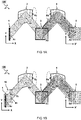
- FIG 1A schematically illustrates a spectrometer 100' with projection optics 2,3,4 affected by undesired curvature R5 in the projected image A5 on the detector array 5.
- projection optics in a spectrometer comprise curved optical surfaces such as mirrors and lenses to shape the projected image.
- the projection optics typically also comprise spectral resolving means such as a grating or prism for redirecting parts of the projected image depending on a wavelength " ⁇ " of the light.
- the projection optics comprise collimation optics 2 configured to collimate light rays originating from the entry slit 1 as a collimated beam onto the spectral resolving element 3.
- the collimation optics 2 comprise parabolic mirror with its focal point coinciding with the entry slit 1.
- the projection optics comprise focusing or imaging optics 4 configured focus the collimated beam onto the detector array 5, i.e. image the entry slit 1.
- focusing or imaging optics 4 comprise a parabolic mirror configured to focus a collimated beam reflected from the grating 3 to a point or line onto an imaging plane coinciding with pixels of the detector array 5.
- the projected image A5 comprises a plurality of spectrally resolved (curved line) images of the straight object line shape A1 at the entry slit 1.
- the detector array 5 may be a two dimensional pixel array wherein light of the entry slit 1 is resolved both as a function of wavelength ⁇ along a first direction X' of the detector array 5 and along a perpendicular second direction Y' corresponding to a length direction Y of the straight object line shape A1 formed by an aperture of the entry slit 1.
- distorting curvature may be caused by projection optics 2,4 having respective curvatures R2,R4 not only around the Y axis but also around the X axis (transverse to the slit).
- the reflection for different beams may occur at different positions (X) transverse to the length of the slit. While the present example show curved mirrors, similar distortions may also occur in other optics, e.g. lenses.
- FIG 1B schematically illustrates an improved spectrometer 100' with correction optics 10 disposed in an optical path directly behind the entry slit 1 and configured to warp the straight object line shape A1 of the entry slit 1 into a curved object line shape B1 from a point of view of the projection optics 2,3,4 and/or detector array 5.
- the warping of the correction optics 10 is configured such that a curvature R1 of the curved object line shape B1 fully, or at least partially, counteracts an otherwise distorting curvature R5 in a projection A5 of the straight object line shape A1 by the projection optics 2,3,4 without the correction optics 10, as was shown in FIG 1A .
- the curvature R5 of the uncorrected image A5 shown in FIG 1A is gone in the corrected image B5, or at least diminished (larger or infinite radius of curvature).
- the spectrally resolved image B5 comprises a plurality of parallel straight projected line shapes formed by spectrally resolved projections of the straight object line shape A1.
- the spectrometer 100 is used to scan an object line by line e.g. by projecting image slices of the object onto the entry slit 1 using additional optics outside the spectrometer 100
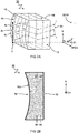
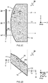
- FIGs 2A-2D schematically show an illustrative embodiment for the correction optics 10 as described herein. In the illustrative figures, some curvatures may be exaggerated to demonstrate desired effects.
- FIG 2A schematically illustrates a perspective view of the embodiment.
- FIG 2B schematically illustrates a front view of the embodiment along a first cylindrical axis C1 of a side surface 12.
- FIG 2C schematically illustrates a side view of the embodiment along a second cylinder axis C2 of a front surface (coinciding with the X axis).
- FIG 2D schematically illustrates a top view of the embodiment along a slit direction Y, i.e. along a length of the entry slit 1.
- the correction optics 10 comprise a cylindrical mirror plane 12 with its curvature R12 around a first cylinder axis C1 in a direction perpendicular to a length Y of the entry slit 1.
- the cylindrical mirror plane as described herein refers to a mirror surface having a curvature in one direction while following a straight line in another, perpendicular direction.
- the curvature may be circular, elliptical, parabolic, or other curved shapes generally following a constant or variable curvature in one direction.
- the cylinder axis as described herein refers to an imaginary axis parallel to the straight lines of the cylindrical mirror plane. For a circular cylinder, this may e.g. be the centerline of the cylinder or any line parallel there to.
- the first cylinder axis C1 is at a first cylinder angle ⁇ 1 with respect a direction Z of principal light rays Le,Lc originating from the entry slit 1.
- the principal light rays may e.g. represent light following a characteristic or shortest optical path through the optics.
- the principal light rays are a collection of initially parallel light rays originating from the entry slit 1 traveling in a direction Z that is perpendicular to a length of the slit (Y).
- the principal rays Lc,Le are also perpendicular to the second cylinder axis C2 of the front surface 11, which in this case coincides with the X axis.
- the first cylinder axis C1 determines a degree of curvature of the curved object line shape B1 compared to the straight object line shape A1.
- This can be understood as follows.
- parallel principal light rays Lc,Le originating from different coordinates Y along the entry slit 1 intersect with the cylindrical mirror plane 12 at intersection points Pc,Pe having different coordinates along the first cylinder axis C1.
- a principle first light ray Lc originating from a center 1c of the entry slit 1 travels another distance to a point of intersection Pc with the cylindrical mirror plane 12 compared to a principle second light ray Le, parallel to the principle first light ray, but originating from an edge 1e of the entry slit 1 and intersecting at point Pe.
- the straight object line shape A1 may be reflected as a curved line shape by reflection off the cylindrical mirror plane 12.
- the cylindrical mirror plane 12 is convex from a point of view of the reflecting light rays Le,Lc.
- a shortest optical path from a center 1c of the entry slit 1 to the convex cylindrical mirror plane 12 is shorter than a shortest optical path from an edge 1e of the entry slit 1 to the convex cylindrical mirror plane 12.
- the correction optics 10 comprise a collimation compensator 11 configured to counteract decollimation of parallel principle light rays Lc,Le originating from the entry slit 1 after reflection by the cylindrical mirror plane 12.
- the collimation compensator 11 is configured to bend principle light rays Lc,Le over a compensation angle ⁇ 11 equal but opposite to a decollimation angle ⁇ 12 at least in a second projection plane YZ perpendicular to the second cylinder axis C2 (shown in FIG 2C ).
- reflected light rays L3 after traversing the collimation compensator 11 and cylindrical mirror plane 12 are parallel to originating light rays L1 before traversing the collimation compensator 11 and cylindrical mirror plane 12 at least in the second projection plane YZ (shown in FIG 2C ).
- the collimation compensator 11 comprises a cylindrical optical surface with its curvature R11 around a second cylinder axis C2 in a direction X perpendicular to a length Y of the entry slit 1.
- the collimation compensator 11 comprises a cylindrical lens or mirror having the opposite collimation effect as the cylindrical mirror plane 12 at least in the plane Y,Z spanned by the principle light rays Le,Lc and/or equivalent mirror planes.
- the second cylinder axis C2 is at a second cylinder angle ⁇ 2 with respect to the first cylinder axis C1.
- the second cylinder axis C2 has a direction X perpendicular to a direction Z of the parallel principle light rays Lc,Le originating from the entry slit 1.
- the collimation compensator 11 is configured to converge principle light rays Lc,Le originating from different parts 1c,1e of the entry slit 1 to compensate a diverging effect of the light rays reflecting off a convex cylindrical mirror plane 12.
- the collimation compensator may be configured to diverge parallel principle light rays to compensate a converging effect of a concave cylindrical mirror (not shown).
- the collimation compensator 11 is disposed in a light path between the entry slit 1 and the cylindrical mirror plane 12.
- the collimation compensator may be disposed in a light path after the cylindrical mirror plane 12 (not shown). Converging the beams before hitting a diverging surface may be more efficient.
- the correction optics 10 comprise a flat mirror plane 13 extending in a direction parallel to the first cylinder axis C1 (indicated in the figures by two parallel lines //).
- the flat mirror plane 13 is configured to reflect light rays L4 in a principal direction Z parallel to original light rays L1 before the cylindrical mirror plane 12 at least in a projection plane XZ perpendicular to a length direction Y of the entry slit 1.
- parallel principle light rays L1 originating from the entry slit 1 remain parallel // to the resulting light rays L5 after traversing the correction optics 10 (both in the YZ plane, as shown in FIG 2C , and the XZ plane, as shown in FIG 2D ). It will be appreciated, as illustrated in FIG 2D , that, compared to the originating principal rays L1, the resulting parallel principle rays L5 after traversing the correction optics 10 are relatively displaced in direction X transverse to a length Y of the slit as a function of their position along the slit to form the curved object line shape B1.
- the correction optics 10 are formed by a monolithic block of material.
- the collimation compensator 11 is formed by a cylindrically curved entry surface of the monolithic block.
- the collimation compensator 11 comprises a positive lens surface from a point of view of the light rays L1 impinging the monolithic block from the front side.
- the cylindrical mirror plane 12 is formed by an internal reflection surface of the monolithic block.
- the cylindrical mirror plane 12 is a concave surface from a point of view outside the monolithic block, or a convex surface from a point of view of the light rays reflecting inside the monolithic block.
- the flat mirror plane 13 comprises a flat surface of the monolithic block opposite the cylindrical mirror plane 12.
- the monolithic block as shown comprises an exit surface 14.
- the exit surface 14 is perpendicular to outgoing principle light rays L4.
- the exit surface 14 is parallel to the second cylinder axis C2 of the front surface forming the collimation compensator 11.
- the monolithic block is shaped as a parallelogram on a projected plane XZ perpendicular to a direction Y of the entry slit 1.
- the second cylinder axis C2 of the curved entry surface forming the collimation compensator 11 and the exit surface 14 are at a non perpendicular angle ⁇ 2 with respect to the first cylinder axis C1 of the cylindrical mirror plane 12 and the flat mirror plane 13.
- the monolithic block is a relatively flat slab of material with some of its surface curved.
- the opposing cylindrical mirror plane 12 and flat mirror plane 13 are relatively close together compared to the opposing entry surface 11 and exit surface 14.
- correction optics 10 for correcting curvature in the projecting of a straight entry slit 1 on a detector array 5 in a spectrometer 100.
- the correction optics 10 comprise one or more of an internal reflection surface forming a cylindrical mirror plane 12 with its curvature R12 around a first cylinder axis C1; a curved entry surface forming a collimation compensator 11 configured to counteract decollimation of parallel principle light rays Lc,Le after reflection by the cylindrical mirror plane 12 (telecentric), wherein the collimation compensator 11 comprises a cylindrical optical surface with its curvature R11 around a second cylinder axis C2 at an angle ⁇ 2 with respect to the first cylinder axis C1; a flat mirror plane 13 extending in a direction parallel // to the first cylinder axis C1; and an exit surface 14 parallel to the second cylinder axis C2.
- Other or further aspects of the present disclosure may be embodied as a method for correcting curvature in the projection of a spectrally resolved image of an entry slit 1 by spectrometer 100 onto a detector array 5.
- the method comprising providing correction optics 10 in an optical path directly behind the entry slit 1 and configuring the correction optics 10 to warp a straight object line shape A1 of the entry slit 1 into a curved object line shape B1 from a point of view of projection optics 2,3,4 in the spectrometer 100 between the correction optics 10 and the detector array 5.
- the warping of the correction optics 10 is configured such that a curvature R1 of the curved object line shape B1 counteracts an otherwise distorting curvature R5 in the projection A5 of the straight object line shape A1 by the projection optics 2,3,4 without the correction optics 10.
- the spectrally resolved image B5 comprises a plurality of parallel straight projected line shapes formed by spectrally resolved projections of the straight object line shape A1.
- the correction optics 10 is positioned within a distance ⁇ Z less than one centimeter from the entry slit 1, preferably less than five millimeter, e.g. between one and three millimeter.
- the entry surface 11 of the monolithic block forming the correction optics 10 is less within this distance ⁇ Z from the entry slit 1. Bringing the correction optics 10 closer to the entry slit, may allow it to act within the (near) field of the slit e.g. acting as a field correction lens.
- the correction optics 10 itself may be relatively small, e.g.
- a size of the correction optics 10 is adjusted to a size of the entry slit 1, e.g. have a size between one and two times a length of the entry slit, e.g. a factor between 1.1 - 1.5 times the length of the slit.
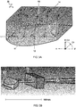
- FIGs 3A-C illustrate an embodiment for the correction optics based computer aided design (CAD).
- FIG 3A illustrates a perspective view of the embodiment with added lines to emphasize the shape of the monolithic block and light rays L1-L5 including points of reflection Pc,Pe at the cylindrical mirror plane 12.
- FIG 3B illustrate the positioning of the correction optics 10 with respect to the entry slit 1 and first projection optics 2' of the spectrometer (not completely shown). Also shown are model calculations of light rays L in various directions and wavelengths traversing the spectrometer.
- FIG 3C shows various view of the embodiment in different directions of as indicated. These views correspond to the illustrative views of the embodiment described with reference to FIGs 2B , 2C,2D .
Landscapes
- Physics & Mathematics (AREA)
- Spectroscopy & Molecular Physics (AREA)
- General Physics & Mathematics (AREA)
- Optics & Photonics (AREA)
- Lenses (AREA)
Abstract
Correction optics (10) are disposed in an optical path directly behind an entry slit (1) of a spectrometer (100) and configured to warp a straight object line shape (A1) of the entry slit (1) into a curved object line shape (B1) from a point of view of the projection optics (2,3,4). The warping of the correction optics (10) is configured such that a curvature (R1) of the curved object line shape (B1) counteracts an otherwise distorting curvature (R5) in a projection (A5) of the straight object line shape (A1) by the projection optics (2,3,4) without the correction optics (10). As a result, the spectrally resolved image (B5) comprises a plurality of parallel straight projected line shapes formed by spectrally resolved projections of the straight object line shape (A1).
Description
- The present disclosure relates to spectrometers, correction optics, and methods for correcting curvature in the projection of a straight entry slit onto a detector array.
- For example,
U.S. patent 4,634,276 discloses configurations of optical systems using two concave mirrors to image an off-axis slit that are used in monochromators or spectrographs in which the coma produced by one mirror is cancelled by that produced by the other mirror. Such systems produce a curved line image of a straight line slit. According to the prior art, this curvature is substantially removed in a two concave mirror optical system in which the off-axis angle and the separation between the mirrors are chosen so that the principal ray from the center of the line object to the first mirror and the principal ray I from the second mirror to the center of the line image are both substantially perpendicular to an axis of symmetry of the optical system which passes through the centers of curvature of the two concave mirrors. The image line is then curved in a plane normal to the image plane and appears substantially straight in the image plane. - It is desired to provide simple correction optics that can be easily inserted into existing spectrometers to variably correct undesired curvature in the projection of a straight entry slit.
- Various aspects of the present disclosure thus provide an improved spectrometer. The spectrometer typically comprises an entry slit configured to receive a one-dimensional image slice of light for spectral analysis along a straight object line shape. Projection optics are configured to project a spectrally resolved two-dimensional image of the straight object line shape onto a detector array. Correction optics as described herein can be disposed in an optical path directly behind the entry slit and configured to warp the straight object line shape of the entry slit into a curved object line shape from a point of view of the projection optics. The warping of the correction optics is configured such that a curvature of the curved object line shape counteracts an otherwise distorting curvature in a projection of the straight object line shape by the projection optics without the correction optics. Accordingly, the spectrally resolved image comprises a plurality of parallel straight projected line shapes formed by spectrally resolved projections of the straight object line shape.
- Some aspects of the present disclosure may be advantageously embodied as a monolithic block of material forming correction optics for correcting curvature in the projecting of a straight entry slit on a detector array in a spectrometer. For example the correction optics may comprise one or more of an internal reflection surface forming a cylindrical mirror plane with its curvature around a first cylinder axis; a curved entry surface forming a collimation compensator configured to counteract decollimation of parallel principle light rays after reflection by the cylindrical mirror plane, wherein the collimation compensator comprises a cylindrical optical surface with its curvature around a second cylinder axis at an angle with respect to the first cylinder axis; a flat mirror plane extending in a direction parallel to the first cylinder axis; and an exit surface parallel to the second cylinder axis.
- Other or further aspects of the present disclosure may be embodied as methods for correcting curvature in the projection of a spectrally resolved image of an entry slit by spectrometer onto a detector array. For example, the method comprises providing correction optics, as described herein, in an optical path directly behind the entry slit and configuring the correction optics to warp a straight object line shape of the entry slit into a curved object line shape from a point of view of projection optics in the spectrometer between the correction optics and the detector array, wherein the warping of the correction optics is configured such that a curvature of the curved object line shape counteracts an otherwise distorting curvature in the projection of the straight object line shape by the projection optics without the correction optics, wherein the spectrally resolved image comprises a plurality of parallel straight projected line shapes formed by spectrally resolved projections of the straight object line shape.
- These and other features, aspects, and advantages of the apparatus, systems and methods of the present disclosure will become better understood from the following description, appended claims, and accompanying drawing wherein:
-
FIGs 1A and 1B schematically illustrate a spectrometer without and with correction optics, respectively; -
FIGs 2A-2D schematically illustrate various views of one embodiment for the correction optics. -
FIGs 3A-3C illustrate various views of another embodiment for the correction optics based on computer aided design. - Terminology used for describing particular embodiments is not intended to be limiting of the invention. As used herein, the singular forms "a", "an" and "the" are intended to include the plural forms as well, unless the context clearly indicates otherwise. The term "and/or" includes any and all combinations of one or more of the associated listed items. It will be understood that the terms "comprises" and/or "comprising" specify the presence of stated features but do not preclude the presence or addition of one or more other features. It will be further understood that when a particular step of a method is referred to as subsequent to another step, it can directly follow said other step or one or more intermediate steps may be carried out before carrying out the particular step, unless specified otherwise. Likewise it will be understood that when a connection between structures or components is described, this connection may be established directly or through intermediate structures or components unless specified otherwise.
- The invention is described more fully hereinafter with reference to the accompanying drawings, in which embodiments of the invention are shown. In the drawings, the absolute and relative sizes of systems, components, layers, and regions may be exaggerated for clarity. Embodiments may be described with reference to schematic and/or cross-section illustrations of possibly idealized embodiments and intermediate structures of the invention. In the description and drawings, like numbers refer to like elements throughout. Relative terms as well as derivatives thereof should be construed to refer to the orientation as then described or as shown in the drawing under discussion. These relative terms are for convenience of description and do not require that the system be constructed or operated in a particular orientation unless stated otherwise.
-
FIG 1A schematically illustrates a spectrometer 100' withprojection optics detector array 5. - Typically, projection optics in a spectrometer comprise curved optical surfaces such as mirrors and lenses to shape the projected image. The projection optics typically also comprise spectral resolving means such as a grating or prism for redirecting parts of the projected image depending on a wavelength "λ" of the light. In some embodiments, the projection optics comprise
collimation optics 2 configured to collimate light rays originating from theentry slit 1 as a collimated beam onto the spectral resolvingelement 3. For example, thecollimation optics 2 comprise parabolic mirror with its focal point coinciding with theentry slit 1. In some embodiments, the projection optics comprise focusing orimaging optics 4 configured focus the collimated beam onto thedetector array 5, i.e. image theentry slit 1. For example, focusing orimaging optics 4 comprise a parabolic mirror configured to focus a collimated beam reflected from thegrating 3 to a point or line onto an imaging plane coinciding with pixels of thedetector array 5. - In the example shown, the projected image A5 comprises a plurality of spectrally resolved (curved line) images of the straight object line shape A1 at the
entry slit 1. For example, thedetector array 5 may be a two dimensional pixel array wherein light of theentry slit 1 is resolved both as a function of wavelength λ along a first direction X' of thedetector array 5 and along a perpendicular second direction Y' corresponding to a length direction Y of the straight object line shape A1 formed by an aperture of theentry slit 1. For example distorting curvature may be caused byprojection optics straight entry slit 1 are projected at an angle onto thecurved mirror 2, the reflection for different beams may occur at different positions (X) transverse to the length of the slit. While the present example show curved mirrors, similar distortions may also occur in other optics, e.g. lenses. - Unfortunately, due to the distorting curvature R5 of the projected line shapes, reconstruction of the image and its spectral components may be difficult, e.g. additional software correction may be needed. Furthermore, effective use of the (rectangular)
detector array 5 may be diminished. -
FIG 1B schematically illustrates an improved spectrometer 100' withcorrection optics 10 disposed in an optical path directly behind theentry slit 1 and configured to warp the straight object line shape A1 of theentry slit 1 into a curved object line shape B1 from a point of view of theprojection optics detector array 5. In the embodiment shown, the warping of thecorrection optics 10 is configured such that a curvature R1 of the curved object line shape B1 fully, or at least partially, counteracts an otherwise distorting curvature R5 in a projection A5 of the straight object line shape A1 by theprojection optics correction optics 10, as was shown inFIG 1A . In other words, the curvature R5 of the uncorrected image A5 shown inFIG 1A is gone in the corrected image B5, or at least diminished (larger or infinite radius of curvature). Accordingly, the spectrally resolved image B5 comprises a plurality of parallel straight projected line shapes formed by spectrally resolved projections of the straight object line shape A1. In some embodiments, thespectrometer 100 is used to scan an object line by line e.g. by projecting image slices of the object onto theentry slit 1 using additional optics outside thespectrometer 100 -
FIGs 2A-2D schematically show an illustrative embodiment for thecorrection optics 10 as described herein. In the illustrative figures, some curvatures may be exaggerated to demonstrate desired effects.FIG 2A schematically illustrates a perspective view of the embodiment.FIG 2B schematically illustrates a front view of the embodiment along a first cylindrical axis C1 of aside surface 12.FIG 2C schematically illustrates a side view of the embodiment along a second cylinder axis C2 of a front surface (coinciding with the X axis).FIG 2D schematically illustrates a top view of the embodiment along a slit direction Y, i.e. along a length of theentry slit 1. - In one embodiment, e.g. as illustrated in
FIGs 2A and 2B , thecorrection optics 10 comprise acylindrical mirror plane 12 with its curvature R12 around a first cylinder axis C1 in a direction perpendicular to a length Y of theentry slit 1. The cylindrical mirror plane as described herein refers to a mirror surface having a curvature in one direction while following a straight line in another, perpendicular direction. The curvature may be circular, elliptical, parabolic, or other curved shapes generally following a constant or variable curvature in one direction. The cylinder axis as described herein refers to an imaginary axis parallel to the straight lines of the cylindrical mirror plane. For a circular cylinder, this may e.g. be the centerline of the cylinder or any line parallel there to. - In one embodiment, e.g. as illustrated in
FIGs 2A and2D , the first cylinder axis C1 is at a first cylinder angle θ1 with respect a direction Z of principal light rays Le,Lc originating from theentry slit 1. The principal light rays may e.g. represent light following a characteristic or shortest optical path through the optics. In the embodiment shown, the principal light rays are a collection of initially parallel light rays originating from the entry slit 1 traveling in a direction Z that is perpendicular to a length of the slit (Y). In the embodiment shown, the principal rays Lc,Le are also perpendicular to the second cylinder axis C2 of thefront surface 11, which in this case coincides with the X axis. - In some embodiments, e.g. as illustrated in
FIG 2A and2D , the first cylinder axis C1 determines a degree of curvature of the curved object line shape B1 compared to the straight object line shape A1. This can be understood as follows. In the embodiment shown, parallel principal light rays Lc,Le originating from different coordinates Y along the entry slit 1 intersect with thecylindrical mirror plane 12 at intersection points Pc,Pe having different coordinates along the first cylinder axis C1. Accordingly, a principle first light ray Lc originating from acenter 1c of the entry slit 1 travels another distance to a point of intersection Pc with thecylindrical mirror plane 12 compared to a principle second light ray Le, parallel to the principle first light ray, but originating from anedge 1e of the entry slit 1 and intersecting at point Pe. In this way, the straight object line shape A1 may be reflected as a curved line shape by reflection off thecylindrical mirror plane 12. In a preferred embodiment, as shown, thecylindrical mirror plane 12 is convex from a point of view of the reflecting light rays Le,Lc. In such embodiment, a shortest optical path from acenter 1c of the entry slit 1 to the convexcylindrical mirror plane 12 is shorter than a shortest optical path from anedge 1e of the entry slit 1 to the convexcylindrical mirror plane 12. - In one embodiment, e.g. as illustrated in
FIGs 2A and2C , thecorrection optics 10 comprise acollimation compensator 11 configured to counteract decollimation of parallel principle light rays Lc,Le originating from the entry slit 1 after reflection by thecylindrical mirror plane 12. In another or further embodiment, thecollimation compensator 11 is configured to bend principle light rays Lc,Le over a compensation angle θ11 equal but opposite to a decollimation angle θ12 at least in a second projection plane YZ perpendicular to the second cylinder axis C2 (shown inFIG 2C ). In a preferred embodiment, reflected light rays L3 after traversing thecollimation compensator 11 andcylindrical mirror plane 12 are parallel to originating light rays L1 before traversing thecollimation compensator 11 andcylindrical mirror plane 12 at least in the second projection plane YZ (shown inFIG 2C ). - In one embodiment, the
collimation compensator 11 comprises a cylindrical optical surface with its curvature R11 around a second cylinder axis C2 in a direction X perpendicular to a length Y of theentry slit 1. In the embodiment illustrated byFIG 2C , thecollimation compensator 11 comprises a cylindrical lens or mirror having the opposite collimation effect as thecylindrical mirror plane 12 at least in the plane Y,Z spanned by the principle light rays Le,Lc and/or equivalent mirror planes. As shown in the perpendicular view ofFIG 2D , the second cylinder axis C2 is at a second cylinder angle θ2 with respect to the first cylinder axis C1. Preferably, the second cylinder axis C2 has a direction X perpendicular to a direction Z of the parallel principle light rays Lc,Le originating from theentry slit 1. In preferred embodiments, thecollimation compensator 11 is configured to converge principle light rays Lc,Le originating fromdifferent parts cylindrical mirror plane 12. Alternatively, the collimation compensator may be configured to diverge parallel principle light rays to compensate a converging effect of a concave cylindrical mirror (not shown). - In the embodiment shown, the
collimation compensator 11 is disposed in a light path between the entry slit 1 and thecylindrical mirror plane 12. Alternatively, though not preferably, the collimation compensator may be disposed in a light path after the cylindrical mirror plane 12 (not shown). Converging the beams before hitting a diverging surface may be more efficient. - In one embodiment, e.g. as illustrated in
FIGs 2A and2D , thecorrection optics 10 comprise aflat mirror plane 13 extending in a direction parallel to the first cylinder axis C1 (indicated in the figures by two parallel lines //). In another or further embodiment, theflat mirror plane 13 is configured to reflect light rays L4 in a principal direction Z parallel to original light rays L1 before thecylindrical mirror plane 12 at least in a projection plane XZ perpendicular to a length direction Y of theentry slit 1. In a preferred embodiment, parallel principle light rays L1 originating from the entry slit 1 remain parallel // to the resulting light rays L5 after traversing the correction optics 10 (both in the YZ plane, as shown inFIG 2C , and the XZ plane, as shown inFIG 2D ). It will be appreciated, as illustrated inFIG 2D , that, compared to the originating principal rays L1, the resulting parallel principle rays L5 after traversing thecorrection optics 10 are relatively displaced in direction X transverse to a length Y of the slit as a function of their position along the slit to form the curved object line shape B1. - In the embodiment shown, the
correction optics 10 are formed by a monolithic block of material. This has advantages of robustness, compactness and easy alignment which has especially advantages in the present applications. Preferably, thecollimation compensator 11 is formed by a cylindrically curved entry surface of the monolithic block. For example, thecollimation compensator 11 comprises a positive lens surface from a point of view of the light rays L1 impinging the monolithic block from the front side. In some embodiments, thecylindrical mirror plane 12 is formed by an internal reflection surface of the monolithic block. For example, thecylindrical mirror plane 12 is a concave surface from a point of view outside the monolithic block, or a convex surface from a point of view of the light rays reflecting inside the monolithic block. In some embodiments, theflat mirror plane 13 comprises a flat surface of the monolithic block opposite thecylindrical mirror plane 12. The monolithic block as shown comprises anexit surface 14. Preferably, theexit surface 14 is perpendicular to outgoing principle light rays L4. - In the embodiment shown, the
exit surface 14 is parallel to the second cylinder axis C2 of the front surface forming thecollimation compensator 11. In some embodiments, the monolithic block is shaped as a parallelogram on a projected plane XZ perpendicular to a direction Y of theentry slit 1. For example, the second cylinder axis C2 of the curved entry surface forming thecollimation compensator 11 and theexit surface 14 are at a non perpendicular angle θ2 with respect to the first cylinder axis C1 of thecylindrical mirror plane 12 and theflat mirror plane 13. Preferably, the monolithic block is a relatively flat slab of material with some of its surface curved. For example, the opposingcylindrical mirror plane 12 andflat mirror plane 13 are relatively close together compared to the opposingentry surface 11 andexit surface 14. - Some aspects of the present disclosure may thus be embodied as a monolithic block of material forming
correction optics 10 for correcting curvature in the projecting of a straight entry slit 1 on adetector array 5 in aspectrometer 100. Preferably, thecorrection optics 10 comprise one or more of an internal reflection surface forming acylindrical mirror plane 12 with its curvature R12 around a first cylinder axis C1; a curved entry surface forming acollimation compensator 11 configured to counteract decollimation of parallel principle light rays Lc,Le after reflection by the cylindrical mirror plane 12 (telecentric), wherein thecollimation compensator 11 comprises a cylindrical optical surface with its curvature R11 around a second cylinder axis C2 at an angle θ2 with respect to the first cylinder axis C1; aflat mirror plane 13 extending in a direction parallel // to the first cylinder axis C1; and anexit surface 14 parallel to the second cylinder axis C2. - Other or further aspects of the present disclosure may be embodied as a method for correcting curvature in the projection of a spectrally resolved image of an
entry slit 1 byspectrometer 100 onto adetector array 5. For example, the method comprising providingcorrection optics 10 in an optical path directly behind the entry slit 1 and configuring thecorrection optics 10 to warp a straight object line shape A1 of the entry slit 1 into a curved object line shape B1 from a point of view ofprojection optics spectrometer 100 between thecorrection optics 10 and thedetector array 5. Preferably, the warping of thecorrection optics 10 is configured such that a curvature R1 of the curved object line shape B1 counteracts an otherwise distorting curvature R5 in the projection A5 of the straight object line shape A1 by theprojection optics correction optics 10. Accordingly the spectrally resolved image B5 comprises a plurality of parallel straight projected line shapes formed by spectrally resolved projections of the straight object line shape A1. - In a preferred embodiment, e.g. as illustrated in
FIG 2C , thecorrection optics 10 is positioned within a distance ΔZ less than one centimeter from the entry slit 1, preferably less than five millimeter, e.g. between one and three millimeter. For example, theentry surface 11 of the monolithic block forming thecorrection optics 10 is less within this distance ΔZ from theentry slit 1. Bringing thecorrection optics 10 closer to the entry slit, may allow it to act within the (near) field of the slit e.g. acting as a field correction lens. Thecorrection optics 10 itself may be relatively small, e.g. extending less than fifty millimeters in its longest dimension, less than thirty millimeters or even less, e.g. between five and thirty millimeters. Typically a size of thecorrection optics 10 is adjusted to a size of the entry slit 1, e.g. have a size between one and two times a length of the entry slit, e.g. a factor between 1.1 - 1.5 times the length of the slit. -
FIGs 3A-C illustrate an embodiment for the correction optics based computer aided design (CAD).FIG 3A illustrates a perspective view of the embodiment with added lines to emphasize the shape of the monolithic block and light rays L1-L5 including points of reflection Pc,Pe at thecylindrical mirror plane 12.FIG 3B illustrate the positioning of thecorrection optics 10 with respect to the entry slit 1 and first projection optics 2' of the spectrometer (not completely shown). Also shown are model calculations of light rays L in various directions and wavelengths traversing the spectrometer.FIG 3C shows various view of the embodiment in different directions of as indicated. These views correspond to the illustrative views of the embodiment described with reference toFIGs 2B ,2C,2D . - For the purpose of clarity and a concise description, features are described herein as part of the same or separate embodiments, however, it will be appreciated that the scope of the invention may include embodiments having combinations of all or some of the features described. For example, while embodiments were shown for a monolithic block of material, also alternative ways may be envisaged by those skilled in the art having the benefit of the present disclosure for achieving a similar function and result. E.g. optical planes or components may be combined or split up into one or more alternative planes. The various elements of the embodiments as discussed and shown offer certain advantages, such as correcting undesired curvature in the projection of a slit in a spectrometer. Of course, it is to be appreciated that any one of the above embodiments or processes may be combined with one or more other embodiments or processes to provide even further improvements in finding and matching designs and advantages. It is appreciated that this disclosure offers particular advantages to spectrometers with two dimensional array sensor, and in general can be applied for any application wherein undesired warping in projection of a straight line needs correcting.
- Finally, the above-discussion is intended to be merely illustrative of the present systems and/or methods and should not be construed as limiting the appended claims to any particular embodiment or group of embodiments. The specification and drawings are accordingly to be regarded in an illustrative manner and are not intended to limit the scope of the appended claims. In interpreting the appended claims, it should be understood that the word "comprising" does not exclude the presence of other elements or acts than those listed in a given claim; the word "a" or "an" preceding an element does not exclude the presence of a plurality of such elements; any reference signs in the claims do not limit their scope; several "means" may be represented by the same or different item(s) or implemented structure or function; any of the disclosed devices or portions thereof may be combined together or separated into further portions unless specifically stated otherwise. The mere fact that certain measures are recited in mutually different claims does not indicate that a combination of these measures cannot be used to advantage. In particular, all working combinations of the claims are considered inherently disclosed.
Claims (15)
- A spectrometer (100) comprising- an entry slit (1) configured to receive a one-dimensional image slice of light for spectral analysis along a straight object line shape (A1);- projection optics (2,3,4) configured to project a spectrally resolved two-dimensional image (B5) of the straight object line shape (A1) onto a detector array (5); and- correction optics (10) disposed in an optical path directly behind the entry slit (1) and configured to warp the straight object line shape (A1) of the entry slit (1) into a curved object line shape (B1) from a point of view of the projection optics (2,3,4), wherein the warping of the correction optics (10) is configured such that a curvature (R1) of the curved object line shape (B1) counteracts an otherwise distorting curvature (R5) in a projection (A5) of the straight object line shape (A1) by the projection optics (2,3,4) without the correction optics (10), wherein the spectrally resolved image (B5) comprises a plurality of parallel straight projected line shapes formed by spectrally resolved projections of the straight object line shape (A1).
- The spectrometer according to claim 1, wherein the correction optics (10) comprise a cylindrical mirror plane (12) with its curvature (R12) around a first cylinder axis (C1) in a direction perpendicular to a length (Y) of the entry slit (1).
- The spectrometer according to claim 2, wherein parallel principal light rays (Lc,Le) originating from different coordinates (Y) along the entry slit (1) intersect with the cylindrical mirror plane (12) at intersection points (Pc,Pe) having different coordinates along the first cylinder axis (C1), wherein a principle first light ray (Lc) originating from a center (1c) of the entry slit (1) travels another distance to a point of intersection (P1) with the cylindrical mirror plane (12) compared to a principle second light ray (Le), parallel to the principle first light ray, but originating from an edge (1e) of the entry slit (1), wherein the straight object line shape (A1) is reflected as a curved line shape by reflection off the cylindrical mirror plane (12).
- The spectrometer according to claim 2 or 3, wherein the cylindrical mirror plane (12) is convex from a point of view of the reflecting light rays (Le,Lc).
- The spectrometer according to any of claims 2-4, wherein the correction optics (10) comprise a collimation compensator (11) configured to counteract decollimation of parallel principle light rays (Lc,Le) originating from the entry slit (1) after reflection by the cylindrical mirror plane (12).
- The spectrometer according to any of claim 5, wherein the collimation compensator (11) is configured to converge principle light rays (Lc,Le) originating from different parts (1c,1e) of the entry slit (1) to compensate a diverging effect of the light rays reflecting off a convex cylindrical mirror plane (12).
- The spectrometer according to any of claim 5 or 6, wherein the collimation compensator (11) is disposed in a light path between the entry slit (1) and the cylindrical mirror plane (12)
- The spectrometer according to any of claims 2-7, wherein the correction optics (10) comprise a flat mirror plane (13) extending in a direction parallel (//) to the first cylinder axis (C1).
- The spectrometer according to any of the preceding claims wherein parallel principle light rays (L1) originating from the entry slit (1) remain parallel (//) to the resulting light rays (L5) after traversing the correction optics (10).
- The spectrometer according to any of the preceding claims, wherein the parallel principle rays (L5) after traversing the correction optics (10) are relatively displaced in direction (X) transverse to a length (Y) of the slit as a function of their position along the slit to form the curved object line shape (B1).
- The spectrometer according to any of the preceding claims wherein the correction optics (10) is positioned within a distance (ΔZ) less than one centimeter from the entry slit (1).
- The spectrometer according to any of the preceding claims wherein the correction optics (10) are formed by a monolithic block of material.
- The spectrometer according to claim 11, wherein the monolithic block comprises an exit surface (14). wherein the exit surface (14) is parallel to the second cylinder axis (C2) of a front surface forming a collimation compensator (11).
- A monolithic block of material forming correction optics (10) for correcting curvature in the projecting of a straight entry slit (1) on a detector array (5) in a spectrometer (100), the correction optics (10) comprising- an internal reflection surface forming a cylindrical mirror plane (12) with its curvature (R12) around a first cylinder axis (C1);- a curved entry surface forming a collimation compensator (11) configured to counteract decollimation of parallel principle light rays (Lc,Le) after reflection by the cylindrical mirror plane (12), wherein the collimation compensator (11) comprises a cylindrical optical surface with its curvature (R11) around a second cylinder axis (C2) at an angle (θ2) with respect to the first cylinder axis (C1);- a flat mirror plane (13) extending in a direction parallel (//) to the first cylinder axis (C1); and- an exit surface (14) parallel to the second cylinder axis (C2).
- A method for correcting curvature in the projection of a spectrally resolved image of an entry slit (1) by spectrometer (100) onto a detector array (5), the method comprising providing the correction optics (10) according to claim 14 in an optical path directly behind the entry slit (1) and configuring the correction optics (10) to warp a straight object line shape (A1) of the entry slit (1) into a curved object line shape (B1) from a point of view of projection optics (2,3,4) in the spectrometer (100) between the correction optics (10) and the detector array (5), wherein the warping of the correction optics (10) is configured such that a curvature (R1) of the curved object line shape (B1) counteracts an otherwise distorting curvature (R5) in the projection (A5) of the straight object line shape (A1) by the projection optics (2,3,4) without the correction optics (10), wherein the spectrally resolved image (B5) comprises a plurality of parallel straight projected line shapes formed by spectrally resolved projections of the straight object line shape (A1).
Priority Applications (4)
| Application Number | Priority Date | Filing Date | Title |
|---|---|---|---|
| EP17170616.1A EP3401656A1 (en) | 2017-05-11 | 2017-05-11 | Correction of curved projection of a spectrometer slit line |
| PCT/NL2018/050084 WO2018147731A1 (en) | 2017-02-08 | 2018-02-07 | Correction of curved projection of a spectrometer slit line |
| EP18707769.8A EP3580537B1 (en) | 2017-02-08 | 2018-02-07 | Correction of curved projection of a spectrometer slit line |
| US16/480,207 US11067441B2 (en) | 2017-02-08 | 2018-02-07 | Correction of curved projection of a spectrometer slit line |
Applications Claiming Priority (1)
| Application Number | Priority Date | Filing Date | Title |
|---|---|---|---|
| EP17170616.1A EP3401656A1 (en) | 2017-05-11 | 2017-05-11 | Correction of curved projection of a spectrometer slit line |
Publications (1)
| Publication Number | Publication Date |
|---|---|
| EP3401656A1 true EP3401656A1 (en) | 2018-11-14 |
Family
ID=58709271
Family Applications (1)
| Application Number | Title | Priority Date | Filing Date |
|---|---|---|---|
| EP17170616.1A Withdrawn EP3401656A1 (en) | 2017-02-08 | 2017-05-11 | Correction of curved projection of a spectrometer slit line |
Country Status (1)
| Country | Link |
|---|---|
| EP (1) | EP3401656A1 (en) |
Cited By (1)
| Publication number | Priority date | Publication date | Assignee | Title |
|---|---|---|---|---|
| CN114841894A (en) * | 2022-05-24 | 2022-08-02 | 青岛理工大学 | Method for correcting spectral distortion |
Citations (4)
| Publication number | Priority date | Publication date | Assignee | Title |
|---|---|---|---|---|
| US4634276A (en) | 1983-06-15 | 1987-01-06 | U.S. Philips Corporation | Slit imaging system using two concave mirrors |
| EP1387154A1 (en) * | 2002-07-31 | 2004-02-04 | Galileo Avionica S.p.A. | Broadband spectrometer with objective comprising an aspheric corrector mirror and a dispersing element traversed twice by the input beam |
| CN101634591A (en) * | 2009-08-21 | 2010-01-27 | 南开大学 | Spectrometer using cylindrical lens for astigmatism correction |
| WO2015093944A1 (en) * | 2013-12-16 | 2015-06-25 | Nederlandse Organisatie Voor Toegepast-Natuurwetenschappelijk Onderzoek Tno | Spectrometer for generating a two dimensional spectrum |
-
2017
- 2017-05-11 EP EP17170616.1A patent/EP3401656A1/en not_active Withdrawn
Patent Citations (4)
| Publication number | Priority date | Publication date | Assignee | Title |
|---|---|---|---|---|
| US4634276A (en) | 1983-06-15 | 1987-01-06 | U.S. Philips Corporation | Slit imaging system using two concave mirrors |
| EP1387154A1 (en) * | 2002-07-31 | 2004-02-04 | Galileo Avionica S.p.A. | Broadband spectrometer with objective comprising an aspheric corrector mirror and a dispersing element traversed twice by the input beam |
| CN101634591A (en) * | 2009-08-21 | 2010-01-27 | 南开大学 | Spectrometer using cylindrical lens for astigmatism correction |
| WO2015093944A1 (en) * | 2013-12-16 | 2015-06-25 | Nederlandse Organisatie Voor Toegepast-Natuurwetenschappelijk Onderzoek Tno | Spectrometer for generating a two dimensional spectrum |
Cited By (2)
| Publication number | Priority date | Publication date | Assignee | Title |
|---|---|---|---|---|
| CN114841894A (en) * | 2022-05-24 | 2022-08-02 | 青岛理工大学 | Method for correcting spectral distortion |
| CN114841894B (en) * | 2022-05-24 | 2024-04-16 | 青岛理工大学 | A method for correcting spectral distortion |
Similar Documents
| Publication | Publication Date | Title |
|---|---|---|
| US11422238B2 (en) | Optical beam director | |
| US10288481B2 (en) | Spectrometer for generating a two dimensional spectrum | |
| EP2697692B1 (en) | Optical scanning apparatus, system and method | |
| US9431795B2 (en) | Laser beam-combining optical device | |
| US8534851B2 (en) | Multiple path substantially symmetric three-mirror anastigmat | |
| US20180164572A1 (en) | Compact telescope having a plurality of focal lengths compensated for by a deformable mirror | |
| CN105518512A (en) | Laser scanner | |
| CN113741030A (en) | Opto-mechanical module | |
| JP4821057B2 (en) | Off-axis reflection optics | |
| US11409199B2 (en) | Pattern drawing device | |
| US9583524B2 (en) | Optical imaging system that incorporates an uni-axial optical homogenizer | |
| EP3580537B1 (en) | Correction of curved projection of a spectrometer slit line | |
| US6703634B2 (en) | 3D-shape measurement apparatus | |
| US10386031B2 (en) | Light device with movable scanning means and optical fiber | |
| RU2327194C2 (en) | Three-mirror optical system without screening | |
| JP6539028B2 (en) | Telescope with active mirror and internal means for monitoring the active mirror | |
| US20130063553A1 (en) | Panoramic Optic Clear Enclosure | |
| US10444606B2 (en) | Projection lens assembly method and projection image display apparatus | |
| WO2019235372A1 (en) | Optical system, and imaging device and imaging system equipped with same | |
| JP2019211711A (en) | Optical system, image capturing device having the same, and image capturing system | |
| JPH10213747A (en) | Reverse telephoto reflection optics | |
| JPH1183626A (en) | Aberration correction spectroscope |
Legal Events
| Date | Code | Title | Description |
|---|---|---|---|
| PUAI | Public reference made under article 153(3) epc to a published international application that has entered the european phase |
Free format text: ORIGINAL CODE: 0009012 |
|
| AK | Designated contracting states |
Kind code of ref document: A1 Designated state(s): AL AT BE BG CH CY CZ DE DK EE ES FI FR GB GR HR HU IE IS IT LI LT LU LV MC MK MT NL NO PL PT RO RS SE SI SK SM TR |
|
| AX | Request for extension of the european patent |
Extension state: BA ME |
|
| STAA | Information on the status of an ep patent application or granted ep patent |
Free format text: STATUS: THE APPLICATION IS DEEMED TO BE WITHDRAWN |
|
| 18D | Application deemed to be withdrawn |
Effective date: 20190515 |