EP3401221A1 - Evacuation system with kiting deterrent - Google Patents
Evacuation system with kiting deterrent Download PDFInfo
- Publication number
- EP3401221A1 EP3401221A1 EP18172069.9A EP18172069A EP3401221A1 EP 3401221 A1 EP3401221 A1 EP 3401221A1 EP 18172069 A EP18172069 A EP 18172069A EP 3401221 A1 EP3401221 A1 EP 3401221A1
- Authority
- EP
- European Patent Office
- Prior art keywords
- tube
- underwing
- evacuation
- slide
- evacuation slide
- Prior art date
- Legal status (The legal status is an assumption and is not a legal conclusion. Google has not performed a legal analysis and makes no representation as to the accuracy of the status listed.)
- Granted
Links
Images



Classifications
-
- B—PERFORMING OPERATIONS; TRANSPORTING
- B64—AIRCRAFT; AVIATION; COSMONAUTICS
- B64D—EQUIPMENT FOR FITTING IN OR TO AIRCRAFT; FLIGHT SUITS; PARACHUTES; ARRANGEMENT OR MOUNTING OF POWER PLANTS OR PROPULSION TRANSMISSIONS IN AIRCRAFT
- B64D25/00—Emergency apparatus or devices, not otherwise provided for
- B64D25/08—Ejecting or escaping means
- B64D25/14—Inflatable escape chutes
-
- B—PERFORMING OPERATIONS; TRANSPORTING
- B63—SHIPS OR OTHER WATERBORNE VESSELS; RELATED EQUIPMENT
- B63B—SHIPS OR OTHER WATERBORNE VESSELS; EQUIPMENT FOR SHIPPING
- B63B27/00—Arrangement of ship-based loading or unloading equipment for cargo or passengers
- B63B27/14—Arrangement of ship-based loading or unloading equipment for cargo or passengers of ramps, gangways or outboard ladders ; Pilot lifts
- B63B27/143—Ramps
- B63B2027/145—Inflatable ramps
-
- B—PERFORMING OPERATIONS; TRANSPORTING
- B63—SHIPS OR OTHER WATERBORNE VESSELS; RELATED EQUIPMENT
- B63C—LAUNCHING, HAULING-OUT, OR DRY-DOCKING OF VESSELS; LIFE-SAVING IN WATER; EQUIPMENT FOR DWELLING OR WORKING UNDER WATER; MEANS FOR SALVAGING OR SEARCHING FOR UNDERWATER OBJECTS
- B63C9/00—Life-saving in water
- B63C9/22—Devices for holding or launching life-buoys, inflatable life-rafts, or other floatable life-saving equipment
Definitions
- the present disclosure relates to aircraft evacuation systems and, in particular, to an evacuation slide having underwing tubes.
- Emergency evacuation systems may be used to exit an aircraft absent a jet way or other suitable means of egress for passengers.
- the evacuation system may deploy from the side of an aircraft fuselage, for example.
- a common problem associated with inflatable evacuation slides, however, is that when such slides are deployed in high lateral wind conditions, the wind may cause the slide to lift or "kite" such that the toe end of the slide does not touch the ground, rendering the slide less usable. If the slide lifts off the ground to a point above the airplane's door sill height after full extension, the slide may block the aircraft exit and prevent safe evacuation of passengers and crew.
- An evacuation system may comprise an evacuation slide comprising an inboard tube and an outboard tube.
- a first underwing tube may be coupled to at least one of the inboard tube or the outboard tube.
- the first underwing tube may comprise a first base portion and first tip portion.
- a width of the first base portion may be greater than a width of the first tip portion.
- the first tip portion may extend away from at least one of the inboard tube or the outboard tube at an angle between 10° and 80°.
- the width of the first base portion may be between 60% and 90% of a width of at least one of the inboard tube or the outboard tube.
- the first underwing tube may comprise a conical shape.
- the evacuation slide may further comprise a transverse support tube extending between the outboard tube and the inboard tube.
- the first base portion of the first underwing tube may be disposed closer to the transverse support tube than to a head end of the evacuation slide.
- the first underwing tube may be in fluid communication with at least one of the inboard tube or the outboard tube.
- a second underwing tube may be coupled to at least one of the inboard tube or the outboard tube.
- the second underwing tube may be in fluid communication with at least one of the inboard tube or the outboard tube.
- a releasable restraint may be coupled to the evacuation slide.
- the first underwing tube may be configured to inflate prior to a separating of the releasable restraint.
- a slide for an evacuation system may comprise an outboard tube and an inboard tube.
- a first underwing tube may be coupled to the outboard tube.
- a second underwing tube may be coupled to the inboard tube.
- a transverse support tube may extend between the outboard tube and the inboard tube.
- a first base portion of the first underwing tube may be disposed closer to the transverse support tube than a head end of the evacuation slide.
- the first underwing tube may comprise a first base portion and a first tip portion, and a width of the first base portion may be greater than a width of the first tip portion.
- the second underwing tube may comprise a second base portion and a second tip portion, and a width of the second base portion may be greater than a width of the second tip portion.
- the first tip portion of the first underwing tube may extend away from the outboard tube at an angle between 10° and 80°.
- the second tip portion of the second underwing tube may extend away from the inboard tube at an angle between 10° and 80°.
- a method of making an evacuation assembly may comprise coupling a first underwing tube to an evacuation slide, and coupling a second underwing tube to the evacuation slide.
- the first underwing tube may be configured to extend away from the evacuation slide.
- the second underwing tube may be configured to extend away from the evacuation slide.
- the method may further comprise configuring the first underwing tube to extend away from the evacuation slide at an angle between 10° and 80°.
- the method may comprise coupling the first underwing tube to an outboard tube of the evacuation slide, and coupling the second underwing tube to an inboard tube of the evacuation slide.
- any reference to singular includes plural embodiments, and any reference to more than one component or step may include a singular embodiment or step.
- any reference to attached, fixed, connected or the like may include permanent, removable, temporary, partial, full and/or any other possible attachment option.
- any reference to without contact (or similar phrases) may also include reduced contact or minimal contact.
- Surface cross hatching lines may be used throughout the figures to denote different parts but not necessarily to denote the same or different materials.
- proximal refers to a direction inward, or generally, towards the reference component.
- Evacuation systems of the present disclosure may include inflatable slides having underwing tubes.
- the underwing tubes may be configured to extend under the wing of an aircraft.
- the underwing tubes may be integral with the inflatable slide and may inflate upon the slide being deployed. Accordingly, in response to the inflatable slide being deployed, the underwing tubes may extend under the wing of the aircraft and may tend to prevent "kiting" or lifting of the slide.
- Evacuation system 100 may comprise an evacuation slide 104.
- Evacuation slide 104 may comprise a head end 106 and a toe end 108, opposite head end 106. Head end 106 may be coupled to an aircraft structure.
- a railing structure 107 may be coupled to head end 106.
- Evacuation slide 104 may comprise an inflatable slide.
- FIG. 1 illustrates evacuation slide 104 in an inflated and/or deployed position.
- Evacuation slide 104 may comprise a sliding surface 110 and an underside surface 112, opposite sliding surface 110. Sliding surface 110 may extend from head end 106 to toe end 108.
- Railing structure 107 may provide a lead-in to sliding surface 110.
- Evacuation slide 104 may comprise an outboard tube 114 and an inboard tube 116. Outboard tube 114 and inboard tube 116 may be disposed on opposing sides of evacuation slide 104. Outboard tube 114 and inboard tube 116 may be integrally formed and in fluid communication. Stated differently, outboard tube 114 and inboard tube 116 may be part of a one interconnected chamber that fills with gas upon deployment of evacuation slide 104.
- evacuation system 100 may comprise one or more underwing tubes 250 coupled to evacuation slide 104.
- Evacuation slide 104 may comprise a single lane slide. However, evacuation slide 104 may comprise any number of lanes. Toe end 108 may contact an exit surface (e.g., the ground) in response to evacuation slide 104 being deployed.
- Aircraft 200 may comprise a fuselage 202 with wings 204 fixed to fuselage 202. Wings 204 may include one or more flaps 205. Emergency exit door 206 may be disposed on fuselage 202 over wing 204 such that passengers exiting emergency exit door 206 would exit onto wing 204.
- Evacuation system 100 may be installed on the aircraft 200 and may be disposed aft of emergency exit door 206.
- a blowout panel 210 may cover evacuation system 100.
- evacuation slide 104 may be stowed behind blowout panel 210.
- evacuation slide 104 may be folded, when in the stowed position.
- evacuation system 100 may jettison blowout panel 210 and evacuation slide 104 may be deployed.
- evacuation system 100 may include and/or be housed within a packboard, which may be mounted to aircraft 200.
- evacuation slide 104 is illustrated in a folded position, in accordance with various embodiments.
- evacuation slide 104 may include a plurality of folds, including first fold 130 and second fold 132, when evacuation slide 104 is in the folded or stowed position.
- a releasable restraint 150 may aid in maintaining first fold 130 and/or second fold 132.
- Releasable restraint 150 may aid in staged deployment of evacuation slide 104.
- Evacuation slide 104 may unfold in response to releasable restraint 150 separating.
- releasable restraint 150 may be configured to separate in response to an internal pressure in evacuation slide 104.
- a gas cylinder may supply a flow of pressurized fluid to evacuation slide 104 in response to evacuation slide 104 being deployed.
- Evacuation slide 104 may begin to inflate and an internal pressure of evacuation slide 104 may increase.
- Releasable restraint 150 may maintain evacuation slide 104 in a folded position until the internal pressure has increased above a predetermined threshold value.
- Releasable restraint 150 may separate once the internal pressure of evacuation slide 104 has increased above the predetermined threshold value.
- Evacuation slide 104 may unfold in response to releasable restraint 150 separating. In this regard, evacuation slide 104 may fully deploy in response to releasable restraint 150 separating.
- releasable restraint 150 may include a first shackle 152 and a second shackle 154.
- releasable restraint 150 may comprise a shear pin restraint.
- a first portion 156 of releasable restraint 150 may decouple from a second portion 158 of releasable restraint 150 in response to a predetermined tensioning force illustrated by arrows 160.
- a first cover 162 and/or a second cover 164 may surround releasable restraint 150.
- Second cover 164 may surround at least a portion of first cover 162.
- First cover 162 and second cover 164 may comprise a fabric.
- first cover 162 and second cover 164 may comprise nylon, ballistic nylon, polypropylene, polyester, cotton, or other suitable material.
- a first strap 166 may be coupled between evacuation slide 104 and releasable restraint 150.
- first strap 166 may be attached to an area of sliding surface 110 of evacuation slide 104 (with momentary reference to FIG. 1 ) and to releasable restraint 150 via first shackle 152.
- An end 172 of first strap 166 may form a loop through which second shackle 154 is located.
- first strap 166 may comprise a rope, tape, ribbon, webbing, or other suitable strap.
- a second strap 168 may be coupled between evacuation slide 104 and releasable restraint 150.
- second strap 168 may be attached to an area of underside surface 112 of evacuation slide 104 (with momentary reference to FIG. 1 ) and to releasable restraint 150 via second shackle 154.
- second strap 168 may be attached to evacuation slide 104 proximate toe end 108, with momentary reference to FIG. 1 .
- An end 174 of second strap 168 may form a loop through which first shackle 152 is located.
- second strap 168 may comprise a rope, tape, ribbon, webbing, or other suitable strap.
- first strap 166 may be attached to evacuation slide 104 proximate head end 106 and second strap 168 may be attached to evacuation slide 104 proximate toe end 108, with momentary reference to FIG. 1 .
- first strap 166 and second strap 168 may be configured to keep evacuation slide 104 in a folded position, until releasable restraint 150 separates.
- evacuation slide 104 may begin to inflate with air. Underside surface 112 of evacuation slide 104 may contact an upper surface 208 of wing 204. Upper surface 208 of wing 204 may be oriented generally away from the exit surface.
- one or more underwing tubes e.g., underwing tube 250a and underwing tube 250b coupled to evacuation slide 104 may begin to inflate. Inflated underwing tubes 250a and 250b may extend away from underside surface 112 of evacuation slide 104 and extend toward under wing 204. Stated another way, inflated underwing tubes 250a and 250b may be located forward an aft portion 212 of wing 204.
- an aft edge of flap 205 may be oriented towards the exit surface (i.e., in a "flap down" position).
- flap 205 being in the flap down position may cause underwing tubes 250a and 250b to extend forward of flap 205 such that flap 205 may be disposed between underside surface 112 of evacuation slide 104 and underwing tubes 250a and 250b.
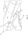
- Underwing tube 250a may be coupled to and may extend from outboard tube 114.
- Underwing tube 250b may be coupled to and may extend from inboard tube 116.
- a base portion of 254a of underwing tube 250a is proximate to outboard tube 114 and may be wider, or have a greater diameter, than a tip portion 256a of underwing tube 250a that is distal to base portion 254a.
- a base portion of 254b of underwing tube 250b is proximate to inboard tube 116 and may be wider, or have a greater diameter, than a tip portion 256b of underwing tube 250b that is distal to base portion 254b.
- underwing tube 250a and underwing tube 250b may comprise a conical shape.
- Base portions 254a and 254b may be connected to outboard tube 114 and inboard tube 116, respectively.
- Tip portions 256a and 256b may be configured to extend toward head end 106.
- Tip portions 256a and 256b may be configured to extend away from outboard tube 114 and inboard tube 116, respectively, upon inflation of underwing tubes 250a and 250b.
- underwing tubes 250a and 250b inflate
- underwing tube 250a and outboard tube 114, and underwing tube 250b and inboard tube 116 may partially define, or bound, a volume which can receive flap 205 and/or aft portion 212 of wing 204, with momentary reference to FIG. 4A .
- underwing tubes 250a and 250b may be disposed between a transverse support tube 260 of evacuation slide 104 and head end 106 of evacuation slide 104.
- transverse support tube 260 may extend between, and provide a fluid connection between, outboard tube 114 and inboard tube 116.
- base portions 254a of underwing tube 250a may be coupled to outboard tube 114 at a location that is between 5% and 60% of a distance 262 between transverse support tube 260 and head end 106.
- base portion 254a of underwing tube 250a may be coupled in close proximity to transverse support tube 260; as used herein, the term "close proximity" means that base portion 254a is coupled closer to transverse support tube 260 than to head end 106. In various embodiments, base portion 254a of underwing tube 250a may be located closer to head end 106 than to toe end 108.
- base portions 254b of underwing tube 250b may be coupled to inboard tube 116 at a location that is between 5% and 60% of a distance 262 between transverse support tube 260 and head end 106.
- base portion 254b of underwing tube 250b may be coupled in close proximity to transverse support tube 260; as used herein, the term "close proximity" means that base portion 254b is coupled closer to transverse support tube 260 than to head end 106.
- base portion 254b of underwing tube 250b may be located closer to head end 106 than to toe end 108.
- Underwing tubes 250a and 250b may be integrally formed with evacuation slide 104.
- underwing tubes 250a and 250b will inflate.
- underwing tube 250a may be in fluid communication with outboard tube 114.
- air may begin to flow into outboard tube 114 and into underwing tube 250a via an opening 251 in outboard tube 114.
- Underwing tube 250b may be in fluid communication with inboard tube 116.
- air may begin to flow into inboard tube 116 and into underwing tube 250b via an opening 252 in inboard tube 116.
- openings 251 and 252 may be configured to allow underwing tubes 250a and 250b to inflate and extend forward flap 205 and/or forward aft portion 212, prior to first fold 130 unfolding. Stated another way, a size of openings 251 and 252 may be selected to control the speed of inflation of underwing tubes 250a and 250b, respectively, such that flap 205 and/or aft portion 212 of wing 204 will be between underside surface 112 of evacuation slide 104 and underwing tubes 250a and 250b prior to releasable restraint 150 separating, with momentary reference to FIG. 3B .
- Underwing tubes 250a and 250b forward flap 205 and/or forward aft portion 212, prior to toe end 108 unfolding from head end 106, may tend to prevent evacuation slide from kiting, as underwing tubes 250a and 250b may hold an upper half of evacuation slide 104 (i.e., an area of evacuation slide 104 between transverse support tube 260 and head end 106) against upper surface 208 of wing 204 when toe end 108 unfolds.
- Underwing tubes 250a and 250b holding the upper half of evacuation slide 104 against upper surface 208 of wing 204 tends to act against lifting or kiting forces that may be caused by wind hitting the underside surface 112 of evacuation slide 104 as toe end 108 unfolds (i.e., as toe end 108 travels towards the exit surface).
- tip portion 256a may extend away from outboard tube 114, and away from underside surface 112, at an angle ⁇ .
- angle ⁇ may be between 5° and 85°. In various embodiments, angle ⁇ may be between 10° and 80°.
- tip portion 256b may extend away from inboard tube 116, and away from underside surface 112, at an angle similar to angle ⁇ . In various embodiments, tip portion 256b may extend away from inboard tube 116 and underside surface 112 at an angle between 5° and 85°.
- tip portion 256b may extend away from inboard tube 116 and underside surface 112 at an angle between 10° and 80°.
- Underwing tubes 250a and 250b may be configured such that, upon inflation, they will extend away from outboard tube 114 and inboard tube 116, respectively, and away underside surface 112 of evacuation slide 104 at an angle that will accommodate flap 205 and/or aft portion 212 of wing 204 extending between underside surface 112 and underwing tubes 250a and 250b.
- a location of base portions 254a and 254b and a length L1 of underwing tube 250a and a length L2 of underwing tube 250b may be selected to allow underwing tubes 250a and 250b to extend forward flap 205 and/or forward aft portion 212 of wing 204, during deployment of evacuation slide 104, with momentary reference to FIG. 4A .
- a width W1 of base portion 254a may be between 50% and 90% of a width W2 of outboard tube 114. Width W2 may correspond to a location where underwing tube 250a is coupled to outboard tube 114. In various embodiments, width W1 of base portion 254b is between 75% and 85% of width W2.
- a width W3 of base portion 254b may be between 50% and 90% of a width W4 of inboard tube 116. Width W4 may correspond to a location where underwing tube 250b is coupled to inboard tube 116. In various embodiments, width W3 of base portion 254b is between 75% and 85% of width W4.
- evacuation slide 104 is illustrated in a fully deployed position, in accordance with various embodiments.
- flap 205 and/or aft portion 212 of wing 204 may be disposed between underwing tubes 250a and 250b and the underside surface 112 of evacuation slide 104.
- underwing tubes 250a and 250b may be disposed forward flap 205 and/or forward aft portion 212 of wing 204.
- flap 205 and/or aft portion 212 of wing 204 may be disposed between underwing tube 250a and outboard tube 114, and flap 205 and/or aft portion 212 of wing 204 may be disposed between underwing tube 250b and inboard tube 116.
- Disposing underwing tubes 250a and 250b forward flap 205 and/or forward aft portion 212 of wing 204 may tend to prevent evacuation slide 104 from kiting, as underwing tubes 250a and 250b may hold the upper half of evacuation slide 104 (i.e., the area of evacuation slide 104 between transverse support tube 260 and head end 106) against upper surface 208 of wing 204.
- Underwing tubes 250a and 250b holding the upper half of evacuation slide 104 against upper surface 208 of wing 204 may tend to act against lifting or kiting forces that may be caused by wind hitting underside surface 112 of evacuation slide 104.
- Method 700 may comprise coupling a first underwing tube to an evacuation slide (step 702), and coupling a second underwing tube to the evacuation slide (step 704).
- the first underwing tube may comprise a first base portion and a first tip portion.
- the first base portion may be coupled to an underside surface of the evacuation slide and the first tip portion may extend away from the underside surface of the evacuation slide.
- the second underwing tube may comprise a second base portion and a second tip portion.
- the second base portion may be coupled to the underside surface of the evacuation slide and the second tip portion may extend away from the underside surface of the evacuation slide.
- step 702 may comprise coupling the first base portion to an outboard tube of the evacuation slide (step 706), and step 704 may comprise coupling the second base portion to an inboard tube of the evacuation slide.
- method 700 may further comprise configuring the first tip portion to extend away from the underside surface of the evacuation slide at an angle between 10° and 80° (step 710).
- step 702 may comprise coupling first underwing tube 250a to evacuation slide 104.
- Step 704 may comprise coupling second underwing tube 250b to evacuation slide 104.
- First underwing tube 250a may comprise first base portion 254a and first tip portion 256a.
- First base portion 254a may be coupled to underside surface 112 of evacuation slide 104 and first tip portion 256a may extend away from underside surface 112 of evacuation slide 104.
- Second underwing tube 250b may comprise second base portion 254b and second tip portion 256b.
- Second base portion 254b may be coupled to underside surface 112 of evacuation slide 104 and second tip portion 256b may extend away from underside surface 112 of evacuation slide 104.
- step 706 may comprise coupling first base portion 254a to outboard tube 114 of evacuation slide 104.
- Step 708 may comprise coupling second base portion 254b to inboard tube 116 of evacuation slide 104.
- Step 710 may comprise configuring first tip portion 256a to extend away from underside surface 112 of evacuation slide 104 at an angle ⁇ between 10° and 80°,
- references to "various embodiments”, “one embodiment”, “an embodiment”, “an example embodiment”, etc. indicate that the embodiment described may include a particular feature, structure, or characteristic, but every embodiment may not necessarily include the particular feature, structure, or characteristic. Moreover, such phrases are not necessarily referring to the same embodiment. Further, when a particular feature, structure, or characteristic is described in connection with an embodiment, it is submitted that it is within the knowledge of one skilled in the art to affect such feature, structure, or characteristic in connection with other embodiments whether or not explicitly described. After reading the description, it will be apparent to one skilled in the relevant art(s) how to implement the disclosure in alternative embodiments.
Landscapes
- Business, Economics & Management (AREA)
- Emergency Management (AREA)
- Engineering & Computer Science (AREA)
- Aviation & Aerospace Engineering (AREA)
- Emergency Lowering Means (AREA)
- Air Bags (AREA)
Abstract
Description
- The present disclosure relates to aircraft evacuation systems and, in particular, to an evacuation slide having underwing tubes.
- Emergency evacuation systems may be used to exit an aircraft absent a jet way or other suitable means of egress for passengers. The evacuation system may deploy from the side of an aircraft fuselage, for example. A common problem associated with inflatable evacuation slides, however, is that when such slides are deployed in high lateral wind conditions, the wind may cause the slide to lift or "kite" such that the toe end of the slide does not touch the ground, rendering the slide less usable. If the slide lifts off the ground to a point above the airplane's door sill height after full extension, the slide may block the aircraft exit and prevent safe evacuation of passengers and crew.
- An evacuation system may comprise an evacuation slide comprising an inboard tube and an outboard tube. A first underwing tube may be coupled to at least one of the inboard tube or the outboard tube.
- In various embodiments, the first underwing tube may comprise a first base portion and first tip portion. A width of the first base portion may be greater than a width of the first tip portion. The first tip portion may extend away from at least one of the inboard tube or the outboard tube at an angle between 10° and 80°. The width of the first base portion may be between 60% and 90% of a width of at least one of the inboard tube or the outboard tube. In various embodiments, the first underwing tube may comprise a conical shape.
- In various embodiments, the evacuation slide may further comprise a transverse support tube extending between the outboard tube and the inboard tube. The first base portion of the first underwing tube may be disposed closer to the transverse support tube than to a head end of the evacuation slide. The first underwing tube may be in fluid communication with at least one of the inboard tube or the outboard tube.
- In various embodiments, a second underwing tube may be coupled to at least one of the inboard tube or the outboard tube. The second underwing tube may be in fluid communication with at least one of the inboard tube or the outboard tube. A releasable restraint may be coupled to the evacuation slide. The first underwing tube may be configured to inflate prior to a separating of the releasable restraint.
- A slide for an evacuation system may comprise an outboard tube and an inboard tube. A first underwing tube may be coupled to the outboard tube. A second underwing tube may be coupled to the inboard tube.
- In various embodiments, a transverse support tube may extend between the outboard tube and the inboard tube. A first base portion of the first underwing tube may be disposed closer to the transverse support tube than a head end of the evacuation slide.
- In various embodiments, the first underwing tube may comprise a first base portion and a first tip portion, and a width of the first base portion may be greater than a width of the first tip portion. The second underwing tube may comprise a second base portion and a second tip portion, and a width of the second base portion may be greater than a width of the second tip portion. The first tip portion of the first underwing tube may extend away from the outboard tube at an angle between 10° and 80°. The second tip portion of the second underwing tube may extend away from the inboard tube at an angle between 10° and 80°.
- A method of making an evacuation assembly may comprise coupling a first underwing tube to an evacuation slide, and coupling a second underwing tube to the evacuation slide. The first underwing tube may be configured to extend away from the evacuation slide. The second underwing tube may be configured to extend away from the evacuation slide.
- In various embodiments, the method may further comprise configuring the first underwing tube to extend away from the evacuation slide at an angle between 10° and 80°. In various embodiments the method may comprise coupling the first underwing tube to an outboard tube of the evacuation slide, and coupling the second underwing tube to an inboard tube of the evacuation slide.
- The foregoing features and elements may be combined in various combinations without exclusivity, unless expressly indicated otherwise. These features and elements as well as the operation thereof will become more apparent in light of the following description and the accompanying drawings. It should be understood, however, the following description and drawings are intended to be exemplary in nature and non-limiting.
- The subject matter of the present disclosure is particularly pointed out and distinctly claimed in the concluding portion of the specification. A more complete understanding of the present disclosure, however, may best be obtained by referring to the detailed description and claims when considered in connection with the figures, wherein like numerals denote like elements.
-
FIG. 1 illustrates a perspective view of an evacuation slide in a deployed position, in accordance with various embodiments; -
FIG. 2 illustrates a perspective view of an aircraft comprising an evacuation system in a stowed position, in accordance with various embodiments; -
FIGs. 3A and 3B illustrate an evacuation slide with a releasable restraint aiding in retaining the evacuation slide in a folded position, in accordance with various embodiments; -
FIGs. 4A ,4B , and4C illustrate a deployment of an evacuation slide comprising underwing tubes, in accordance with various embodiments; -
FIG. 5 illustrates an evacuation slide comprising underwing tubes, in accordance with various embodiments; and -
FIGs. 6 and 7 illustrate a method of making an evacuation assembly, in accordance with various embodiments. - The detailed description of exemplary embodiments herein makes reference to the accompanying drawings, which show exemplary embodiments by way of illustration. While these exemplary embodiments are described in sufficient detail to enable those skilled in the art to practice the exemplary embodiments of the disclosure, it should be understood that other embodiments may be realized and that logical changes and adaptations in design and construction may be made in accordance with this disclosure and the teachings herein. Thus, the detailed description herein is presented for purposes of illustration only and not limitation. The steps recited in any of the method or process descriptions may be executed in any order and are not necessarily limited to the order presented.
- Furthermore, any reference to singular includes plural embodiments, and any reference to more than one component or step may include a singular embodiment or step. Also, any reference to attached, fixed, connected or the like may include permanent, removable, temporary, partial, full and/or any other possible attachment option. Additionally, any reference to without contact (or similar phrases) may also include reduced contact or minimal contact. Surface cross hatching lines may be used throughout the figures to denote different parts but not necessarily to denote the same or different materials.
- Throughout the present disclosure, like reference numbers denote like elements. Accordingly, elements with like element numbering may be shown in the figures, but may not be necessarily be repeated herein for the sake of clarity.
- As used herein, "aft" refers to the direction associated with the tail (i.e., the back end) of an aircraft, or generally, to the direction of exhaust of the gas turbine. As used herein, "forward" refers to the direction associated with the nose (i.e., the front end) of an aircraft, or generally, to the direction of flight or motion. As used herein, "distal" refers to the direction outward, or generally, away from a reference component. As used herein, "proximal" and/or "proximate" refers to a direction inward, or generally, towards the reference component.
- Evacuation systems of the present disclosure may include inflatable slides having underwing tubes. In various embodiments, the underwing tubes may be configured to extend under the wing of an aircraft. The underwing tubes may be integral with the inflatable slide and may inflate upon the slide being deployed. Accordingly, in response to the inflatable slide being deployed, the underwing tubes may extend under the wing of the aircraft and may tend to prevent "kiting" or lifting of the slide.
- With reference to
FIG. 1 , anevacuation system 100 is illustrated, in accordance with various embodiments.Evacuation system 100 may comprise anevacuation slide 104.Evacuation slide 104 may comprise ahead end 106 and atoe end 108, oppositehead end 106.Head end 106 may be coupled to an aircraft structure. In various embodiments, arailing structure 107 may be coupled tohead end 106.Evacuation slide 104 may comprise an inflatable slide.FIG. 1 illustratesevacuation slide 104 in an inflated and/or deployed position.Evacuation slide 104 may comprise a slidingsurface 110 and anunderside surface 112, opposite slidingsurface 110. Slidingsurface 110 may extend fromhead end 106 to toeend 108.Railing structure 107 may provide a lead-in to slidingsurface 110.Evacuation slide 104 may comprise anoutboard tube 114 and aninboard tube 116.Outboard tube 114 andinboard tube 116 may be disposed on opposing sides ofevacuation slide 104.Outboard tube 114 andinboard tube 116 may be integrally formed and in fluid communication. Stated differently,outboard tube 114 andinboard tube 116 may be part of a one interconnected chamber that fills with gas upon deployment ofevacuation slide 104. In various embodiments,evacuation system 100 may comprise one ormore underwing tubes 250 coupled toevacuation slide 104.Evacuation slide 104 may comprise a single lane slide. However,evacuation slide 104 may comprise any number of lanes.Toe end 108 may contact an exit surface (e.g., the ground) in response toevacuation slide 104 being deployed. - Referring to
FIG. 2 , anexemplary aircraft 200 withevacuation system 100 in a stowed position is shown, in accordance with various embodiments.Aircraft 200 may comprise afuselage 202 withwings 204 fixed tofuselage 202.Wings 204 may include one or more flaps 205.Emergency exit door 206 may be disposed onfuselage 202 overwing 204 such that passengers exitingemergency exit door 206 would exit ontowing 204.Evacuation system 100 may be installed on theaircraft 200 and may be disposed aft ofemergency exit door 206. Ablowout panel 210 may coverevacuation system 100. In this regard, with combined reference toFIG. 1 anFIG. 2 ,evacuation slide 104 may be stowed behindblowout panel 210. In various embodiments,evacuation slide 104 may be folded, when in the stowed position. In response toemergency exit door 206 opening or in response to another evacuation event,evacuation system 100 may jettisonblowout panel 210 andevacuation slide 104 may be deployed. In various embodiments,evacuation system 100 may include and/or be housed within a packboard, which may be mounted toaircraft 200. - With reference to
FIG. 3A and FIG. 3B ,evacuation slide 104 is illustrated in a folded position, in accordance with various embodiments. For example,evacuation slide 104 may include a plurality of folds, includingfirst fold 130 andsecond fold 132, whenevacuation slide 104 is in the folded or stowed position. Areleasable restraint 150 may aid in maintainingfirst fold 130 and/orsecond fold 132.Releasable restraint 150 may aid in staged deployment ofevacuation slide 104.Evacuation slide 104 may unfold in response toreleasable restraint 150 separating. - In various embodiments,
releasable restraint 150 may be configured to separate in response to an internal pressure inevacuation slide 104. For example, a gas cylinder may supply a flow of pressurized fluid toevacuation slide 104 in response toevacuation slide 104 being deployed.Evacuation slide 104 may begin to inflate and an internal pressure ofevacuation slide 104 may increase.Releasable restraint 150 may maintainevacuation slide 104 in a folded position until the internal pressure has increased above a predetermined threshold value.Releasable restraint 150 may separate once the internal pressure ofevacuation slide 104 has increased above the predetermined threshold value.Evacuation slide 104 may unfold in response toreleasable restraint 150 separating. In this regard,evacuation slide 104 may fully deploy in response toreleasable restraint 150 separating. - In various embodiments,
releasable restraint 150 may include afirst shackle 152 and asecond shackle 154. In various embodiments,releasable restraint 150 may comprise a shear pin restraint. In this regard, afirst portion 156 ofreleasable restraint 150 may decouple from asecond portion 158 ofreleasable restraint 150 in response to a predetermined tensioning force illustrated byarrows 160. Afirst cover 162 and/or asecond cover 164 may surroundreleasable restraint 150.Second cover 164 may surround at least a portion offirst cover 162.First cover 162 andsecond cover 164 may comprise a fabric. For example,first cover 162 andsecond cover 164 may comprise nylon, ballistic nylon, polypropylene, polyester, cotton, or other suitable material. - A
first strap 166 may be coupled betweenevacuation slide 104 andreleasable restraint 150. For example,first strap 166 may be attached to an area of slidingsurface 110 of evacuation slide 104 (with momentary reference toFIG. 1 ) and toreleasable restraint 150 viafirst shackle 152. Anend 172 offirst strap 166 may form a loop through whichsecond shackle 154 is located. In various embodiments,first strap 166 may comprise a rope, tape, ribbon, webbing, or other suitable strap. - A
second strap 168 may be coupled betweenevacuation slide 104 andreleasable restraint 150. For example,second strap 168 may be attached to an area ofunderside surface 112 of evacuation slide 104 (with momentary reference toFIG. 1 ) and toreleasable restraint 150 viasecond shackle 154. In various embodiments,second strap 168 may be attached toevacuation slide 104proximate toe end 108, with momentary reference toFIG. 1 . Anend 174 ofsecond strap 168 may form a loop through whichfirst shackle 152 is located. In various embodiments,second strap 168 may comprise a rope, tape, ribbon, webbing, or other suitable strap. In various embodiments,first strap 166 may be attached toevacuation slide 104 proximatehead end 106 andsecond strap 168 may be attached toevacuation slide 104proximate toe end 108, with momentary reference toFIG. 1 . In this regard,first strap 166 andsecond strap 168 may be configured to keepevacuation slide 104 in a folded position, untilreleasable restraint 150 separates. - With reference to
FIG. 4A , a deployment ofevacuation slide 104 is illustrated, in accordance with various embodiments. During deployment,evacuation slide 104 may begin to inflate with air.Underside surface 112 ofevacuation slide 104 may contact anupper surface 208 ofwing 204.Upper surface 208 ofwing 204 may be oriented generally away from the exit surface. Asevacuation slide 104 inflates, one or more underwing tubes (e.g.,underwing tube 250a andunderwing tube 250b) coupled toevacuation slide 104 may begin to inflate.Inflated underwing tubes underside surface 112 ofevacuation slide 104 and extend toward underwing 204. Stated another way,inflated underwing tubes aft portion 212 ofwing 204. - During deployment of
evacuation slide 104, an aft edge offlap 205 may be oriented towards the exit surface (i.e., in a "flap down" position). In various embodiments,flap 205 being in the flap down position may causeunderwing tubes flap 205 such thatflap 205 may be disposed betweenunderside surface 112 ofevacuation slide 104 andunderwing tubes - With reference to
FIG. 5 ,underside surface 112 ofevacuation slide 104 is illustrated, in accordance with various embodiments.Underwing tube 250a may be coupled to and may extend fromoutboard tube 114.Underwing tube 250b may be coupled to and may extend frominboard tube 116. In various embodiments, a base portion of 254a ofunderwing tube 250a is proximate tooutboard tube 114 and may be wider, or have a greater diameter, than atip portion 256a ofunderwing tube 250a that is distal tobase portion 254a. A base portion of 254b ofunderwing tube 250b is proximate toinboard tube 116 and may be wider, or have a greater diameter, than atip portion 256b ofunderwing tube 250b that is distal to base portion 254b. In various embodiments,underwing tube 250a andunderwing tube 250b may comprise a conical shape. -
Base portions 254a and 254b may be connected tooutboard tube 114 andinboard tube 116, respectively.Tip portions head end 106.Tip portions outboard tube 114 andinboard tube 116, respectively, upon inflation ofunderwing tubes underwing tubes underwing tube 250a andoutboard tube 114, andunderwing tube 250b andinboard tube 116 may partially define, or bound, a volume which can receiveflap 205 and/oraft portion 212 ofwing 204, with momentary reference toFIG. 4A . - In various embodiments,
underwing tubes transverse support tube 260 ofevacuation slide 104 andhead end 106 ofevacuation slide 104. In various embodiments,transverse support tube 260 may extend between, and provide a fluid connection between,outboard tube 114 andinboard tube 116. In various embodiments,base portions 254a ofunderwing tube 250a may be coupled tooutboard tube 114 at a location that is between 5% and 60% of adistance 262 betweentransverse support tube 260 andhead end 106. In various embodiments,base portion 254a ofunderwing tube 250a may be coupled in close proximity totransverse support tube 260; as used herein, the term "close proximity" means thatbase portion 254a is coupled closer totransverse support tube 260 than tohead end 106. In various embodiments,base portion 254a ofunderwing tube 250a may be located closer tohead end 106 than to toeend 108. - In various embodiments, base portions 254b of
underwing tube 250b may be coupled toinboard tube 116 at a location that is between 5% and 60% of adistance 262 betweentransverse support tube 260 andhead end 106. In various embodiments, base portion 254b ofunderwing tube 250b may be coupled in close proximity totransverse support tube 260; as used herein, the term "close proximity" means that base portion 254b is coupled closer totransverse support tube 260 than tohead end 106. In various embodiments, base portion 254b ofunderwing tube 250b may be located closer tohead end 106 than to toeend 108. -
Underwing tubes evacuation slide 104. In various embodiments, asevacuation slide 104 inflates,underwing tubes underwing tube 250a may be in fluid communication withoutboard tube 114. Upon deployment ofevacuation slide 104, air may begin to flow intooutboard tube 114 and intounderwing tube 250a via anopening 251 inoutboard tube 114.Underwing tube 250b may be in fluid communication withinboard tube 116. Upon deployment ofevacuation slide 104, air may begin to flow intoinboard tube 116 and intounderwing tube 250b via anopening 252 ininboard tube 116. - With reference to
FIG. 4A andFIG. 5 ,openings underwing tubes forward flap 205 and/or forwardaft portion 212, prior tofirst fold 130 unfolding. Stated another way, a size ofopenings underwing tubes flap 205 and/oraft portion 212 ofwing 204 will be betweenunderside surface 112 ofevacuation slide 104 andunderwing tubes releasable restraint 150 separating, with momentary reference toFIG. 3B . Disposingunderwing tubes forward flap 205 and/or forwardaft portion 212, prior to toe end 108 unfolding fromhead end 106, may tend to prevent evacuation slide from kiting, asunderwing tubes evacuation slide 104 betweentransverse support tube 260 and head end 106) againstupper surface 208 ofwing 204 whentoe end 108 unfolds.Underwing tubes evacuation slide 104 againstupper surface 208 ofwing 204 tends to act against lifting or kiting forces that may be caused by wind hitting theunderside surface 112 ofevacuation slide 104 astoe end 108 unfolds (i.e., astoe end 108 travels towards the exit surface). - With reference to
FIG. 4B , deployment ofevacuation slide 104 is illustrated, withaircraft 200 removed for clarity. Asunderwing tube 250a inflates,tip portion 256a may extend away fromoutboard tube 114, and away fromunderside surface 112, at an angle α. In various embodiments, angle α may be between 5° and 85°. In various embodiments, angle α may be between 10° and 80°. Similarly, asunderwing tube 250b inflates,tip portion 256b, with momentary reference toFIG. 5 , may extend away frominboard tube 116, and away fromunderside surface 112, at an angle similar to angle α. In various embodiments,tip portion 256b may extend away frominboard tube 116 andunderside surface 112 at an angle between 5° and 85°. In various embodiments,tip portion 256b may extend away frominboard tube 116 andunderside surface 112 at an angle between 10° and 80°.Underwing tubes outboard tube 114 andinboard tube 116, respectively, and awayunderside surface 112 ofevacuation slide 104 at an angle that will accommodateflap 205 and/oraft portion 212 ofwing 204 extending betweenunderside surface 112 andunderwing tubes - Returning to
FIG. 5 , a location ofbase portions 254a and 254b and a length L1 ofunderwing tube 250a and a length L2 ofunderwing tube 250b may be selected to allowunderwing tubes forward flap 205 and/or forwardaft portion 212 ofwing 204, during deployment ofevacuation slide 104, with momentary reference toFIG. 4A . - In various embodiments, a width W1 of
base portion 254a may be between 50% and 90% of a width W2 ofoutboard tube 114. Width W2 may correspond to a location whereunderwing tube 250a is coupled tooutboard tube 114. In various embodiments, width W1 of base portion 254b is between 75% and 85% of width W2. - In various embodiments, a width W3 of base portion 254b may be between 50% and 90% of a width W4 of
inboard tube 116. Width W4 may correspond to a location whereunderwing tube 250b is coupled toinboard tube 116. In various embodiments, width W3 of base portion 254b is between 75% and 85% of width W4. - With reference to
FIG. 4C ,evacuation slide 104 is illustrated in a fully deployed position, in accordance with various embodiments. With reference toFIG. 4C andFIG. 5 ,flap 205 and/oraft portion 212 ofwing 204 may be disposed betweenunderwing tubes underside surface 112 ofevacuation slide 104. Stated another way,underwing tubes forward flap 205 and/or forwardaft portion 212 ofwing 204. For example,flap 205 and/oraft portion 212 ofwing 204 may be disposed betweenunderwing tube 250a andoutboard tube 114, andflap 205 and/oraft portion 212 ofwing 204 may be disposed betweenunderwing tube 250b andinboard tube 116. Disposingunderwing tubes forward flap 205 and/or forwardaft portion 212 ofwing 204, may tend to preventevacuation slide 104 from kiting, asunderwing tubes evacuation slide 104 betweentransverse support tube 260 and head end 106) againstupper surface 208 ofwing 204.Underwing tubes evacuation slide 104 againstupper surface 208 ofwing 204 may tend to act against lifting or kiting forces that may be caused by wind hittingunderside surface 112 ofevacuation slide 104. - With reference to
FIG. 6 , amethod 700 of making an evacuation assembly is illustrated, in accordance with various embodiments.Method 700 may comprise coupling a first underwing tube to an evacuation slide (step 702), and coupling a second underwing tube to the evacuation slide (step 704). The first underwing tube may comprise a first base portion and a first tip portion. The first base portion may be coupled to an underside surface of the evacuation slide and the first tip portion may extend away from the underside surface of the evacuation slide. The second underwing tube may comprise a second base portion and a second tip portion. The second base portion may be coupled to the underside surface of the evacuation slide and the second tip portion may extend away from the underside surface of the evacuation slide. - With reference to
FIG. 7 , in various embodiments,step 702 may comprise coupling the first base portion to an outboard tube of the evacuation slide (step 706), and step 704 may comprise coupling the second base portion to an inboard tube of the evacuation slide. In various embodiments,method 700 may further comprise configuring the first tip portion to extend away from the underside surface of the evacuation slide at an angle between 10° and 80° (step 710). - In various embodiments, with combined reference to
FIG. 4A andFIG. 6 , step 702 may comprise couplingfirst underwing tube 250a toevacuation slide 104. Step 704 may comprise couplingsecond underwing tube 250b toevacuation slide 104.First underwing tube 250a may comprisefirst base portion 254a andfirst tip portion 256a.First base portion 254a may be coupled tounderside surface 112 ofevacuation slide 104 andfirst tip portion 256a may extend away fromunderside surface 112 ofevacuation slide 104.Second underwing tube 250b may comprise second base portion 254b andsecond tip portion 256b. Second base portion 254b may be coupled tounderside surface 112 ofevacuation slide 104 andsecond tip portion 256b may extend away fromunderside surface 112 ofevacuation slide 104. - In various embodiments, with combined reference to
FIG. 4A ,FIG. 4B , andFIG. 7 , step 706 may comprise couplingfirst base portion 254a tooutboard tube 114 ofevacuation slide 104. Step 708 may comprise coupling second base portion 254b toinboard tube 116 ofevacuation slide 104. Step 710 may comprise configuringfirst tip portion 256a to extend away fromunderside surface 112 ofevacuation slide 104 at an angle α between 10° and 80°, - Benefits and other advantages have been described herein with regard to specific embodiments. Furthermore, the connecting lines shown in the various figures contained herein are intended to represent exemplary functional relationships and/or physical couplings between the various elements. It should be noted that many alternative or additional functional relationships or physical connections may be present in a practical system. However, the benefits, advantages, and any elements that may cause any benefit or advantage to occur or become more pronounced are not to be construed as critical, required, or essential features or elements of the disclosure. The scope of the disclosure is accordingly to be limited by nothing other than the appended claims, in which reference to an element in the singular is not intended to mean "one and only one" unless explicitly so stated, but rather "one or more." Moreover, where a phrase similar to "at least one of A, B, or C" is used in the claims, it is intended that the phrase be interpreted to mean that A alone may be present in an embodiment, B alone may be present in an embodiment, C alone may be present in an embodiment, or that any combination of the elements A, B and C may be present in a single embodiment; for example, A and B, A and C, B and C, or A and B and C.
- Systems, methods and apparatus are provided herein. In the detailed description herein, references to "various embodiments", "one embodiment", "an embodiment", "an example embodiment", etc., indicate that the embodiment described may include a particular feature, structure, or characteristic, but every embodiment may not necessarily include the particular feature, structure, or characteristic. Moreover, such phrases are not necessarily referring to the same embodiment. Further, when a particular feature, structure, or characteristic is described in connection with an embodiment, it is submitted that it is within the knowledge of one skilled in the art to affect such feature, structure, or characteristic in connection with other embodiments whether or not explicitly described. After reading the description, it will be apparent to one skilled in the relevant art(s) how to implement the disclosure in alternative embodiments.
Claims (15)
- An evacuation system, comprising:an evacuation slide (104) comprising an inboard tube (116) and an outboard tube (114); anda first underwing tube (250a) coupled to at least one of the outboard tube of the evacuation slide or the inboard tube of the evacuation slide.
- The evacuation system of claim 1, wherein the first underwing tube comprises a first base portion (254a) and a first tip portion (256a), and wherein a width of the first base portion is greater than a width of the first tip portion.
- The evacuation system of claim 2, wherein the first tip portion extends away from at least one of the outboard tube or the inboard tube at an angle between 10° and 80°.
- The evacuation system of claim 2, wherein the width of the first base portion is between 60% and 90% of a width of at least one of the outboard tube or the inboard tube.
- The evacuation system of any preceding claim, wherein the first underwing tube (250a) comprises a conical shape.
- The evacuation system of any preceding claim, wherein the evacuation slide further comprises a transverse support tube (260) extending between the outboard tube and the inboard tube, and preferably wherein a first base portion of the first underwing tube is disposed closer to the transverse support tube than to a head end (106) of the evacuation slide.
- The evacuation system of any preceding claim, wherein the first underwing tube is in fluid communication with at least one of the outboard tube or the inboard tube.
- The evacuation system of any preceding claim, further comprising a second underwing tube (250b) coupled to at least one of the outboard tube or the inboard tube, and preferably wherein the second underwing tube is in fluid communication with at least one of the outboard tube or the inboard tube.
- The evacuation system of any preceding claim, further comprising a releasable restraint (150) coupled to the evacuation slide, wherein the first underwing tube is configured to inflate prior to a separating of the releasable restraint.
- A slide for an evacuation system, comprising:an outboard tube (114);an inboard tube (116);a first underwing tube (250a) coupled to the outboard tube; anda second underwing tube (250b) coupled to the inboard tube.
- The slide of claim 10, further comprising a transverse support tube (260) extending between the outboard tube and the inboard tube, and preferably wherein a first base portion (254a) of the first underwing tube is disposed closer to the transverse support tube than a head end (106) of the slide.
- The slide of claim 10, wherein the first underwing tube comprises a first base portion (254a) and a first tip portion (256a), and wherein a width of the first base portion is greater than a width of the first tip portion; and
wherein the second underwing tube (250b) comprises a second base portion (254b) and a second tip portion (256b), and wherein a width of the second base portion is greater than a width of the second tip portion. - The slide of claim 12, wherein the first tip portion of the first underwing tube extends away from the outboard tube at an angle between 10° and 80°, or wherein the second tip portion of the second underwing tube extends away from the inboard tube at an angle between 10° and 80.
- A method of making an evacuation assembly, comprising
coupling a first underwing tube to an evacuation slide, wherein the first underwing tube is configured to extend away from the evacuation slide; and
coupling a second underwing tube to the evacuation slide, wherein the second underwing tube is configured to extend away from the evacuation slide. - The method of claim 14, further comprising configuring the first underwing tube to extend away from the evacuation slide at an angle between 10° and 80°, and preferably
wherein the coupling the first underwing tube to the evacuation slide comprises coupling the first underwing tube to an outboard tube of the evacuation slide; and
wherein the coupling the second underwing tube to the evacuation slide comprises coupling the second underling tube to an inboard tube of the evacuation slide.
Applications Claiming Priority (1)
| Application Number | Priority Date | Filing Date | Title |
|---|---|---|---|
| US15/594,389 US10793280B2 (en) | 2017-05-12 | 2017-05-12 | Evacuation system with wind lift deterrent |
Publications (2)
| Publication Number | Publication Date |
|---|---|
| EP3401221A1 true EP3401221A1 (en) | 2018-11-14 |
| EP3401221B1 EP3401221B1 (en) | 2022-09-07 |
Family
ID=62165427
Family Applications (1)
| Application Number | Title | Priority Date | Filing Date |
|---|---|---|---|
| EP18172069.9A Active EP3401221B1 (en) | 2017-05-12 | 2018-05-14 | Evacuation system with kiting deterrent |
Country Status (2)
| Country | Link |
|---|---|
| US (1) | US10793280B2 (en) |
| EP (1) | EP3401221B1 (en) |
Families Citing this family (6)
| Publication number | Priority date | Publication date | Assignee | Title |
|---|---|---|---|---|
| US10836498B2 (en) * | 2017-03-22 | 2020-11-17 | Goodrich Corporation | Light weight variable force restraint |
| US10647436B2 (en) * | 2017-04-27 | 2020-05-12 | Goodrich Corporation | Yoke strap with shock absorber |
| US10494110B2 (en) | 2017-05-18 | 2019-12-03 | Goodrich Corporation | Evacuation slide restraint |
| US10647437B2 (en) | 2017-09-25 | 2020-05-12 | Goodrich Corporation | Continuously tensioned truss strap |
| US10640220B2 (en) * | 2017-10-24 | 2020-05-05 | Goodrich Corporation | Anti-kiting device |
| US20210354836A1 (en) * | 2020-05-12 | 2021-11-18 | Goodrich Corporation | Symmetrical dual action restraint |
Citations (5)
| Publication number | Priority date | Publication date | Assignee | Title |
|---|---|---|---|---|
| US3845920A (en) * | 1972-01-14 | 1974-11-05 | Sargent Industries | Inflatable evacuation ramp |
| EP0034357A2 (en) * | 1980-02-19 | 1981-08-26 | The B.F. GOODRICH Company | Aircraft comprising an escape slide |
| EP0096594A2 (en) * | 1982-06-09 | 1983-12-21 | The Garrett Corporation | Inflatable slide |
| US4846422A (en) * | 1984-05-14 | 1989-07-11 | The Bfgoodrich Company | Single piece evacuation system for aircraft or the like |
| US20080191097A1 (en) * | 2007-02-13 | 2008-08-14 | The Boeing Company | Multi-exit combined evacuation slide |
Family Cites Families (20)
| Publication number | Priority date | Publication date | Assignee | Title |
|---|---|---|---|---|
| US3606939A (en) * | 1969-03-06 | 1971-09-21 | Garrett Corp | Inflatable escape slide |
| US3973645A (en) * | 1975-08-15 | 1976-08-10 | The Garrett Corporation | Inflatable evacuation slide |
| US4013247A (en) * | 1975-12-30 | 1977-03-22 | The Boeing Company | Mechanical support apparatus for the stabilization of an inflatable escape slide |
| US4018321A (en) * | 1976-05-21 | 1977-04-19 | The B. F. Goodrich Company | Escape slide and platform assembly |
| US4486422A (en) * | 1982-11-22 | 1984-12-04 | The Dow Chemical Company | Insecticidal phosphorus derivatives of 5-pyrimidinols |
| US5360186A (en) * | 1993-07-26 | 1994-11-01 | The B. F. Goodrich Company | Inflatable slide raft assembly |
| US5820773A (en) * | 1997-03-13 | 1998-10-13 | The B. F. Goodrich Company | Escape slide with support tube assembly |
| US5906340A (en) * | 1997-05-29 | 1999-05-25 | The B.F. Goodrich Company | Inflatable escape slide assembly |
| US5975467A (en) * | 1998-08-06 | 1999-11-02 | Air Cruisers Company | Inflatable evacuation slide |
| US6443259B1 (en) * | 2001-10-11 | 2002-09-03 | Goodrich Corporation | Passive deployment readiness indicator for aircraft evacuation slide |
| US6814183B2 (en) * | 2002-10-17 | 2004-11-09 | Goodrich Corporation | Extensible evacuation slide |
| US6877696B2 (en) | 2002-12-19 | 2005-04-12 | Goodrich Corporation | Evacuation slide with leading edge spoiler |
| US8215586B2 (en) * | 2009-04-08 | 2012-07-10 | Air Cruisers Company | Evacuation slide systems |
| US9139305B2 (en) | 2013-02-11 | 2015-09-22 | Air Cruisers Company | Evacuation systems |
| US10131440B2 (en) * | 2016-09-16 | 2018-11-20 | Goodrich Corporation | Inflatable evacuation system with canopy support |
| US10647436B2 (en) * | 2017-04-27 | 2020-05-12 | Goodrich Corporation | Yoke strap with shock absorber |
| US20180319507A1 (en) * | 2017-05-04 | 2018-11-08 | Goodrich Corporation | Evacuation slide connector |
| US10494110B2 (en) * | 2017-05-18 | 2019-12-03 | Goodrich Corporation | Evacuation slide restraint |
| US10640219B2 (en) * | 2017-08-25 | 2020-05-05 | Goodrich Corporation | Energetic evacuation slide |
| US10640220B2 (en) * | 2017-10-24 | 2020-05-05 | Goodrich Corporation | Anti-kiting device |
-
2017
- 2017-05-12 US US15/594,389 patent/US10793280B2/en active Active
-
2018
- 2018-05-14 EP EP18172069.9A patent/EP3401221B1/en active Active
Patent Citations (5)
| Publication number | Priority date | Publication date | Assignee | Title |
|---|---|---|---|---|
| US3845920A (en) * | 1972-01-14 | 1974-11-05 | Sargent Industries | Inflatable evacuation ramp |
| EP0034357A2 (en) * | 1980-02-19 | 1981-08-26 | The B.F. GOODRICH Company | Aircraft comprising an escape slide |
| EP0096594A2 (en) * | 1982-06-09 | 1983-12-21 | The Garrett Corporation | Inflatable slide |
| US4846422A (en) * | 1984-05-14 | 1989-07-11 | The Bfgoodrich Company | Single piece evacuation system for aircraft or the like |
| US20080191097A1 (en) * | 2007-02-13 | 2008-08-14 | The Boeing Company | Multi-exit combined evacuation slide |
Also Published As
| Publication number | Publication date |
|---|---|
| US10793280B2 (en) | 2020-10-06 |
| EP3401221B1 (en) | 2022-09-07 |
| US20180327101A1 (en) | 2018-11-15 |
Similar Documents
| Publication | Publication Date | Title |
|---|---|---|
| EP3401221B1 (en) | Evacuation system with kiting deterrent | |
| US10752368B2 (en) | Asymmetric yoke | |
| US10414506B2 (en) | Aircraft parachute system utilizing airbag to assist with parachute deployment | |
| US11964769B2 (en) | Light weight variable force restraint | |
| EP3241752B1 (en) | Systems and methods for retaining removable panel when deploying evacuation system | |
| EP3348482A1 (en) | Light weight restraint for evacuation slide systems | |
| US10647436B2 (en) | Yoke strap with shock absorber | |
| EP3348481B1 (en) | Secondary release arrangement for evacuation slide systems | |
| EP3348483A1 (en) | Shock absorbing evacuation system restraint | |
| US9169008B2 (en) | Method of arranging a buoyancy system on an aircraft, a buoyancy system for an aircraft, and an aircraft | |
| EP3348485B1 (en) | Continuously restrained evacuation system | |
| US20210053661A1 (en) | Integrated lifeline and geometric restraint | |
| US11554871B2 (en) | Truss strap integrated geometric restraint | |
| EP3816051A1 (en) | Integrated truss restraint | |
| US4462562A (en) | Self-deploying afterbody apparatus for an ejection seat | |
| US20070114332A1 (en) | Softer-parachute deployment deceleration assist device | |
| EP3398856A1 (en) | Releasable bulkhead |
Legal Events
| Date | Code | Title | Description |
|---|---|---|---|
| PUAI | Public reference made under article 153(3) epc to a published international application that has entered the european phase |
Free format text: ORIGINAL CODE: 0009012 |
|
| STAA | Information on the status of an ep patent application or granted ep patent |
Free format text: STATUS: THE APPLICATION HAS BEEN PUBLISHED |
|
| AK | Designated contracting states |
Kind code of ref document: A1 Designated state(s): AL AT BE BG CH CY CZ DE DK EE ES FI FR GB GR HR HU IE IS IT LI LT LU LV MC MK MT NL NO PL PT RO RS SE SI SK SM TR |
|
| AX | Request for extension of the european patent |
Extension state: BA ME |
|
| STAA | Information on the status of an ep patent application or granted ep patent |
Free format text: STATUS: REQUEST FOR EXAMINATION WAS MADE |
|
| 17P | Request for examination filed |
Effective date: 20190514 |
|
| RBV | Designated contracting states (corrected) |
Designated state(s): AL AT BE BG CH CY CZ DE DK EE ES FI FR GB GR HR HU IE IS IT LI LT LU LV MC MK MT NL NO PL PT RO RS SE SI SK SM TR |
|
| STAA | Information on the status of an ep patent application or granted ep patent |
Free format text: STATUS: EXAMINATION IS IN PROGRESS |
|
| 17Q | First examination report despatched |
Effective date: 20191022 |
|
| GRAP | Despatch of communication of intention to grant a patent |
Free format text: ORIGINAL CODE: EPIDOSNIGR1 |
|
| STAA | Information on the status of an ep patent application or granted ep patent |
Free format text: STATUS: GRANT OF PATENT IS INTENDED |
|
| INTG | Intention to grant announced |
Effective date: 20220413 |
|
| RIN1 | Information on inventor provided before grant (corrected) |
Inventor name: SCHMIDT, RYAN Inventor name: HAYNES, TIMOTHY C. |
|
| GRAS | Grant fee paid |
Free format text: ORIGINAL CODE: EPIDOSNIGR3 |
|
| GRAA | (expected) grant |
Free format text: ORIGINAL CODE: 0009210 |
|
| STAA | Information on the status of an ep patent application or granted ep patent |
Free format text: STATUS: THE PATENT HAS BEEN GRANTED |
|
| AK | Designated contracting states |
Kind code of ref document: B1 Designated state(s): AL AT BE BG CH CY CZ DE DK EE ES FI FR GB GR HR HU IE IS IT LI LT LU LV MC MK MT NL NO PL PT RO RS SE SI SK SM TR |
|
| REG | Reference to a national code |
Ref country code: GB Ref legal event code: FG4D |
|
| REG | Reference to a national code |
Ref country code: CH Ref legal event code: EP Ref country code: AT Ref legal event code: REF Ref document number: 1516871 Country of ref document: AT Kind code of ref document: T Effective date: 20220915 |
|
| REG | Reference to a national code |
Ref country code: IE Ref legal event code: FG4D |
|
| REG | Reference to a national code |
Ref country code: DE Ref legal event code: R096 Ref document number: 602018040230 Country of ref document: DE |
|
| REG | Reference to a national code |
Ref country code: LT Ref legal event code: MG9D |
|
| REG | Reference to a national code |
Ref country code: NL Ref legal event code: MP Effective date: 20220907 |
|
| PG25 | Lapsed in a contracting state [announced via postgrant information from national office to epo] |
Ref country code: SE Free format text: LAPSE BECAUSE OF FAILURE TO SUBMIT A TRANSLATION OF THE DESCRIPTION OR TO PAY THE FEE WITHIN THE PRESCRIBED TIME-LIMIT Effective date: 20220907 Ref country code: RS Free format text: LAPSE BECAUSE OF FAILURE TO SUBMIT A TRANSLATION OF THE DESCRIPTION OR TO PAY THE FEE WITHIN THE PRESCRIBED TIME-LIMIT Effective date: 20220907 Ref country code: NO Free format text: LAPSE BECAUSE OF FAILURE TO SUBMIT A TRANSLATION OF THE DESCRIPTION OR TO PAY THE FEE WITHIN THE PRESCRIBED TIME-LIMIT Effective date: 20221207 Ref country code: LV Free format text: LAPSE BECAUSE OF FAILURE TO SUBMIT A TRANSLATION OF THE DESCRIPTION OR TO PAY THE FEE WITHIN THE PRESCRIBED TIME-LIMIT Effective date: 20220907 Ref country code: LT Free format text: LAPSE BECAUSE OF FAILURE TO SUBMIT A TRANSLATION OF THE DESCRIPTION OR TO PAY THE FEE WITHIN THE PRESCRIBED TIME-LIMIT Effective date: 20220907 Ref country code: FI Free format text: LAPSE BECAUSE OF FAILURE TO SUBMIT A TRANSLATION OF THE DESCRIPTION OR TO PAY THE FEE WITHIN THE PRESCRIBED TIME-LIMIT Effective date: 20220907 |
|
| REG | Reference to a national code |
Ref country code: AT Ref legal event code: MK05 Ref document number: 1516871 Country of ref document: AT Kind code of ref document: T Effective date: 20220907 |
|
| PG25 | Lapsed in a contracting state [announced via postgrant information from national office to epo] |
Ref country code: HR Free format text: LAPSE BECAUSE OF FAILURE TO SUBMIT A TRANSLATION OF THE DESCRIPTION OR TO PAY THE FEE WITHIN THE PRESCRIBED TIME-LIMIT Effective date: 20220907 Ref country code: GR Free format text: LAPSE BECAUSE OF FAILURE TO SUBMIT A TRANSLATION OF THE DESCRIPTION OR TO PAY THE FEE WITHIN THE PRESCRIBED TIME-LIMIT Effective date: 20221208 |
|
| PG25 | Lapsed in a contracting state [announced via postgrant information from national office to epo] |
Ref country code: SM Free format text: LAPSE BECAUSE OF FAILURE TO SUBMIT A TRANSLATION OF THE DESCRIPTION OR TO PAY THE FEE WITHIN THE PRESCRIBED TIME-LIMIT Effective date: 20220907 Ref country code: RO Free format text: LAPSE BECAUSE OF FAILURE TO SUBMIT A TRANSLATION OF THE DESCRIPTION OR TO PAY THE FEE WITHIN THE PRESCRIBED TIME-LIMIT Effective date: 20220907 Ref country code: PT Free format text: LAPSE BECAUSE OF FAILURE TO SUBMIT A TRANSLATION OF THE DESCRIPTION OR TO PAY THE FEE WITHIN THE PRESCRIBED TIME-LIMIT Effective date: 20230109 Ref country code: ES Free format text: LAPSE BECAUSE OF FAILURE TO SUBMIT A TRANSLATION OF THE DESCRIPTION OR TO PAY THE FEE WITHIN THE PRESCRIBED TIME-LIMIT Effective date: 20220907 Ref country code: CZ Free format text: LAPSE BECAUSE OF FAILURE TO SUBMIT A TRANSLATION OF THE DESCRIPTION OR TO PAY THE FEE WITHIN THE PRESCRIBED TIME-LIMIT Effective date: 20220907 Ref country code: AT Free format text: LAPSE BECAUSE OF FAILURE TO SUBMIT A TRANSLATION OF THE DESCRIPTION OR TO PAY THE FEE WITHIN THE PRESCRIBED TIME-LIMIT Effective date: 20220907 |
|
| PG25 | Lapsed in a contracting state [announced via postgrant information from national office to epo] |
Ref country code: SK Free format text: LAPSE BECAUSE OF FAILURE TO SUBMIT A TRANSLATION OF THE DESCRIPTION OR TO PAY THE FEE WITHIN THE PRESCRIBED TIME-LIMIT Effective date: 20220907 Ref country code: PL Free format text: LAPSE BECAUSE OF FAILURE TO SUBMIT A TRANSLATION OF THE DESCRIPTION OR TO PAY THE FEE WITHIN THE PRESCRIBED TIME-LIMIT Effective date: 20220907 Ref country code: IS Free format text: LAPSE BECAUSE OF FAILURE TO SUBMIT A TRANSLATION OF THE DESCRIPTION OR TO PAY THE FEE WITHIN THE PRESCRIBED TIME-LIMIT Effective date: 20230107 Ref country code: EE Free format text: LAPSE BECAUSE OF FAILURE TO SUBMIT A TRANSLATION OF THE DESCRIPTION OR TO PAY THE FEE WITHIN THE PRESCRIBED TIME-LIMIT Effective date: 20220907 |
|
| REG | Reference to a national code |
Ref country code: DE Ref legal event code: R097 Ref document number: 602018040230 Country of ref document: DE |
|
| P01 | Opt-out of the competence of the unified patent court (upc) registered |
Effective date: 20230522 |
|
| PG25 | Lapsed in a contracting state [announced via postgrant information from national office to epo] |
Ref country code: NL Free format text: LAPSE BECAUSE OF FAILURE TO SUBMIT A TRANSLATION OF THE DESCRIPTION OR TO PAY THE FEE WITHIN THE PRESCRIBED TIME-LIMIT Effective date: 20220907 Ref country code: AL Free format text: LAPSE BECAUSE OF FAILURE TO SUBMIT A TRANSLATION OF THE DESCRIPTION OR TO PAY THE FEE WITHIN THE PRESCRIBED TIME-LIMIT Effective date: 20220907 |
|
| PLBE | No opposition filed within time limit |
Free format text: ORIGINAL CODE: 0009261 |
|
| STAA | Information on the status of an ep patent application or granted ep patent |
Free format text: STATUS: NO OPPOSITION FILED WITHIN TIME LIMIT |
|
| PG25 | Lapsed in a contracting state [announced via postgrant information from national office to epo] |
Ref country code: DK Free format text: LAPSE BECAUSE OF FAILURE TO SUBMIT A TRANSLATION OF THE DESCRIPTION OR TO PAY THE FEE WITHIN THE PRESCRIBED TIME-LIMIT Effective date: 20220907 |
|
| 26N | No opposition filed |
Effective date: 20230608 |
|
| PG25 | Lapsed in a contracting state [announced via postgrant information from national office to epo] |
Ref country code: SI Free format text: LAPSE BECAUSE OF FAILURE TO SUBMIT A TRANSLATION OF THE DESCRIPTION OR TO PAY THE FEE WITHIN THE PRESCRIBED TIME-LIMIT Effective date: 20220907 |
|
| REG | Reference to a national code |
Ref country code: CH Ref legal event code: PL |
|
| PG25 | Lapsed in a contracting state [announced via postgrant information from national office to epo] |
Ref country code: MC Free format text: LAPSE BECAUSE OF FAILURE TO SUBMIT A TRANSLATION OF THE DESCRIPTION OR TO PAY THE FEE WITHIN THE PRESCRIBED TIME-LIMIT Effective date: 20220907 |
|
| GBPC | Gb: european patent ceased through non-payment of renewal fee |
Effective date: 20230514 |
|
| REG | Reference to a national code |
Ref country code: BE Ref legal event code: MM Effective date: 20230531 |
|
| PG25 | Lapsed in a contracting state [announced via postgrant information from national office to epo] |
Ref country code: MC Free format text: LAPSE BECAUSE OF FAILURE TO SUBMIT A TRANSLATION OF THE DESCRIPTION OR TO PAY THE FEE WITHIN THE PRESCRIBED TIME-LIMIT Effective date: 20220907 Ref country code: LU Free format text: LAPSE BECAUSE OF NON-PAYMENT OF DUE FEES Effective date: 20230514 Ref country code: LI Free format text: LAPSE BECAUSE OF NON-PAYMENT OF DUE FEES Effective date: 20230531 Ref country code: CH Free format text: LAPSE BECAUSE OF NON-PAYMENT OF DUE FEES Effective date: 20230531 |
|
| REG | Reference to a national code |
Ref country code: IE Ref legal event code: MM4A |
|
| PG25 | Lapsed in a contracting state [announced via postgrant information from national office to epo] |
Ref country code: IE Free format text: LAPSE BECAUSE OF NON-PAYMENT OF DUE FEES Effective date: 20230514 |
|
| PG25 | Lapsed in a contracting state [announced via postgrant information from national office to epo] |
Ref country code: IE Free format text: LAPSE BECAUSE OF NON-PAYMENT OF DUE FEES Effective date: 20230514 Ref country code: GB Free format text: LAPSE BECAUSE OF NON-PAYMENT OF DUE FEES Effective date: 20230514 |
|
| PG25 | Lapsed in a contracting state [announced via postgrant information from national office to epo] |
Ref country code: BE Free format text: LAPSE BECAUSE OF NON-PAYMENT OF DUE FEES Effective date: 20230531 |
|
| PG25 | Lapsed in a contracting state [announced via postgrant information from national office to epo] |
Ref country code: BG Free format text: LAPSE BECAUSE OF FAILURE TO SUBMIT A TRANSLATION OF THE DESCRIPTION OR TO PAY THE FEE WITHIN THE PRESCRIBED TIME-LIMIT Effective date: 20220907 |
|
| PG25 | Lapsed in a contracting state [announced via postgrant information from national office to epo] |
Ref country code: BG Free format text: LAPSE BECAUSE OF FAILURE TO SUBMIT A TRANSLATION OF THE DESCRIPTION OR TO PAY THE FEE WITHIN THE PRESCRIBED TIME-LIMIT Effective date: 20220907 |
|
| PGFP | Annual fee paid to national office [announced via postgrant information from national office to epo] |
Ref country code: DE Payment date: 20250423 Year of fee payment: 8 |
|
| PGFP | Annual fee paid to national office [announced via postgrant information from national office to epo] |
Ref country code: IT Payment date: 20250423 Year of fee payment: 8 |
|
| PGFP | Annual fee paid to national office [announced via postgrant information from national office to epo] |
Ref country code: FR Payment date: 20250423 Year of fee payment: 8 |
|
| PG25 | Lapsed in a contracting state [announced via postgrant information from national office to epo] |
Ref country code: CY Free format text: LAPSE BECAUSE OF FAILURE TO SUBMIT A TRANSLATION OF THE DESCRIPTION OR TO PAY THE FEE WITHIN THE PRESCRIBED TIME-LIMIT; INVALID AB INITIO Effective date: 20180514 |
|
| PG25 | Lapsed in a contracting state [announced via postgrant information from national office to epo] |
Ref country code: HU Free format text: LAPSE BECAUSE OF FAILURE TO SUBMIT A TRANSLATION OF THE DESCRIPTION OR TO PAY THE FEE WITHIN THE PRESCRIBED TIME-LIMIT; INVALID AB INITIO Effective date: 20180514 |
|
| PG25 | Lapsed in a contracting state [announced via postgrant information from national office to epo] |
Ref country code: TR Free format text: LAPSE BECAUSE OF FAILURE TO SUBMIT A TRANSLATION OF THE DESCRIPTION OR TO PAY THE FEE WITHIN THE PRESCRIBED TIME-LIMIT Effective date: 20220907 |