EP3401179A1 - A device for controlling a maneuver of a vehicle - Google Patents
A device for controlling a maneuver of a vehicle Download PDFInfo
- Publication number
- EP3401179A1 EP3401179A1 EP18170651.6A EP18170651A EP3401179A1 EP 3401179 A1 EP3401179 A1 EP 3401179A1 EP 18170651 A EP18170651 A EP 18170651A EP 3401179 A1 EP3401179 A1 EP 3401179A1
- Authority
- EP
- European Patent Office
- Prior art keywords
- suited
- access system
- maneuver
- vehicle
- communication circuit
- Prior art date
- Legal status (The legal status is an assumption and is not a legal conclusion. Google has not performed a legal analysis and makes no representation as to the accuracy of the status listed.)
- Withdrawn
Links
Images

Classifications
-
- G—PHYSICS
- G07—CHECKING-DEVICES
- G07C—TIME OR ATTENDANCE REGISTERS; REGISTERING OR INDICATING THE WORKING OF MACHINES; GENERATING RANDOM NUMBERS; VOTING OR LOTTERY APPARATUS; ARRANGEMENTS, SYSTEMS OR APPARATUS FOR CHECKING NOT PROVIDED FOR ELSEWHERE
- G07C9/00—Individual registration on entry or exit
- G07C9/00174—Electronically operated locks; Circuits therefor; Nonmechanical keys therefor, e.g. passive or active electrical keys or other data carriers without mechanical keys
-
- B—PERFORMING OPERATIONS; TRANSPORTING
- B60—VEHICLES IN GENERAL
- B60W—CONJOINT CONTROL OF VEHICLE SUB-UNITS OF DIFFERENT TYPE OR DIFFERENT FUNCTION; CONTROL SYSTEMS SPECIALLY ADAPTED FOR HYBRID VEHICLES; ROAD VEHICLE DRIVE CONTROL SYSTEMS FOR PURPOSES NOT RELATED TO THE CONTROL OF A PARTICULAR SUB-UNIT
- B60W30/00—Purposes of road vehicle drive control systems not related to the control of a particular sub-unit, e.g. of systems using conjoint control of vehicle sub-units
- B60W30/06—Automatic manoeuvring for parking
-
- B—PERFORMING OPERATIONS; TRANSPORTING
- B60—VEHICLES IN GENERAL
- B60W—CONJOINT CONTROL OF VEHICLE SUB-UNITS OF DIFFERENT TYPE OR DIFFERENT FUNCTION; CONTROL SYSTEMS SPECIALLY ADAPTED FOR HYBRID VEHICLES; ROAD VEHICLE DRIVE CONTROL SYSTEMS FOR PURPOSES NOT RELATED TO THE CONTROL OF A PARTICULAR SUB-UNIT
- B60W50/00—Details of control systems for road vehicle drive control not related to the control of a particular sub-unit, e.g. process diagnostic or vehicle driver interfaces
- B60W50/08—Interaction between the driver and the control system
-
- B—PERFORMING OPERATIONS; TRANSPORTING
- B62—LAND VEHICLES FOR TRAVELLING OTHERWISE THAN ON RAILS
- B62D—MOTOR VEHICLES; TRAILERS
- B62D1/00—Steering controls, i.e. means for initiating a change of direction of the vehicle
-
- B—PERFORMING OPERATIONS; TRANSPORTING
- B62—LAND VEHICLES FOR TRAVELLING OTHERWISE THAN ON RAILS
- B62D—MOTOR VEHICLES; TRAILERS
- B62D15/00—Steering not otherwise provided for
- B62D15/02—Steering position indicators ; Steering position determination; Steering aids
- B62D15/027—Parking aids, e.g. instruction means
-
- B—PERFORMING OPERATIONS; TRANSPORTING
- B62—LAND VEHICLES FOR TRAVELLING OTHERWISE THAN ON RAILS
- B62D—MOTOR VEHICLES; TRAILERS
- B62D15/00—Steering not otherwise provided for
- B62D15/02—Steering position indicators ; Steering position determination; Steering aids
- B62D15/027—Parking aids, e.g. instruction means
- B62D15/0285—Parking performed automatically
-
- E—FIXED CONSTRUCTIONS
- E05—LOCKS; KEYS; WINDOW OR DOOR FITTINGS; SAFES
- E05F—DEVICES FOR MOVING WINGS INTO OPEN OR CLOSED POSITION; CHECKS FOR WINGS; WING FITTINGS NOT OTHERWISE PROVIDED FOR, CONCERNED WITH THE FUNCTIONING OF THE WING
- E05F15/00—Power-operated mechanisms for wings
- E05F15/70—Power-operated mechanisms for wings with automatic actuation
- E05F15/77—Power-operated mechanisms for wings with automatic actuation using wireless control
-
- H—ELECTRICITY
- H04—ELECTRIC COMMUNICATION TECHNIQUE
- H04L—TRANSMISSION OF DIGITAL INFORMATION, e.g. TELEGRAPHIC COMMUNICATION
- H04L67/00—Network arrangements or protocols for supporting network services or applications
- H04L67/01—Protocols
- H04L67/12—Protocols specially adapted for proprietary or special-purpose networking environments, e.g. medical networks, sensor networks, networks in vehicles or remote metering networks
- H04L67/125—Protocols specially adapted for proprietary or special-purpose networking environments, e.g. medical networks, sensor networks, networks in vehicles or remote metering networks involving control of end-device applications over a network
-
- B—PERFORMING OPERATIONS; TRANSPORTING
- B60—VEHICLES IN GENERAL
- B60W—CONJOINT CONTROL OF VEHICLE SUB-UNITS OF DIFFERENT TYPE OR DIFFERENT FUNCTION; CONTROL SYSTEMS SPECIALLY ADAPTED FOR HYBRID VEHICLES; ROAD VEHICLE DRIVE CONTROL SYSTEMS FOR PURPOSES NOT RELATED TO THE CONTROL OF A PARTICULAR SUB-UNIT
- B60W2540/00—Input parameters relating to occupants
- B60W2540/215—Selection or confirmation of options
-
- B—PERFORMING OPERATIONS; TRANSPORTING
- B60—VEHICLES IN GENERAL
- B60W—CONJOINT CONTROL OF VEHICLE SUB-UNITS OF DIFFERENT TYPE OR DIFFERENT FUNCTION; CONTROL SYSTEMS SPECIALLY ADAPTED FOR HYBRID VEHICLES; ROAD VEHICLE DRIVE CONTROL SYSTEMS FOR PURPOSES NOT RELATED TO THE CONTROL OF A PARTICULAR SUB-UNIT
- B60W2556/00—Input parameters relating to data
- B60W2556/45—External transmission of data to or from the vehicle
- B60W2556/55—External transmission of data to or from the vehicle using telemetry
-
- E—FIXED CONSTRUCTIONS
- E05—LOCKS; KEYS; WINDOW OR DOOR FITTINGS; SAFES
- E05Y—INDEXING SCHEME ASSOCIATED WITH SUBCLASSES E05D AND E05F, RELATING TO CONSTRUCTION ELEMENTS, ELECTRIC CONTROL, POWER SUPPLY, POWER SIGNAL OR TRANSMISSION, USER INTERFACES, MOUNTING OR COUPLING, DETAILS, ACCESSORIES, AUXILIARY OPERATIONS NOT OTHERWISE PROVIDED FOR, APPLICATION THEREOF
- E05Y2900/00—Application of doors, windows, wings or fittings thereof
- E05Y2900/10—Application of doors, windows, wings or fittings thereof for buildings or parts thereof
- E05Y2900/106—Application of doors, windows, wings or fittings thereof for buildings or parts thereof for garages
-
- E—FIXED CONSTRUCTIONS
- E05—LOCKS; KEYS; WINDOW OR DOOR FITTINGS; SAFES
- E05Y—INDEXING SCHEME ASSOCIATED WITH SUBCLASSES E05D AND E05F, RELATING TO CONSTRUCTION ELEMENTS, ELECTRIC CONTROL, POWER SUPPLY, POWER SIGNAL OR TRANSMISSION, USER INTERFACES, MOUNTING OR COUPLING, DETAILS, ACCESSORIES, AUXILIARY OPERATIONS NOT OTHERWISE PROVIDED FOR, APPLICATION THEREOF
- E05Y2900/00—Application of doors, windows, wings or fittings thereof
- E05Y2900/10—Application of doors, windows, wings or fittings thereof for buildings or parts thereof
- E05Y2900/13—Type of wing
- E05Y2900/132—Doors
-
- G—PHYSICS
- G07—CHECKING-DEVICES
- G07C—TIME OR ATTENDANCE REGISTERS; REGISTERING OR INDICATING THE WORKING OF MACHINES; GENERATING RANDOM NUMBERS; VOTING OR LOTTERY APPARATUS; ARRANGEMENTS, SYSTEMS OR APPARATUS FOR CHECKING NOT PROVIDED FOR ELSEWHERE
- G07C9/00—Individual registration on entry or exit
- G07C9/00174—Electronically operated locks; Circuits therefor; Nonmechanical keys therefor, e.g. passive or active electrical keys or other data carriers without mechanical keys
- G07C2009/00753—Electronically operated locks; Circuits therefor; Nonmechanical keys therefor, e.g. passive or active electrical keys or other data carriers without mechanical keys operated by active electrical keys
- G07C2009/00769—Electronically operated locks; Circuits therefor; Nonmechanical keys therefor, e.g. passive or active electrical keys or other data carriers without mechanical keys operated by active electrical keys with data transmission performed by wireless means
-
- G—PHYSICS
- G07—CHECKING-DEVICES
- G07C—TIME OR ATTENDANCE REGISTERS; REGISTERING OR INDICATING THE WORKING OF MACHINES; GENERATING RANDOM NUMBERS; VOTING OR LOTTERY APPARATUS; ARRANGEMENTS, SYSTEMS OR APPARATUS FOR CHECKING NOT PROVIDED FOR ELSEWHERE
- G07C9/00—Individual registration on entry or exit
- G07C9/00174—Electronically operated locks; Circuits therefor; Nonmechanical keys therefor, e.g. passive or active electrical keys or other data carriers without mechanical keys
- G07C9/00896—Electronically operated locks; Circuits therefor; Nonmechanical keys therefor, e.g. passive or active electrical keys or other data carriers without mechanical keys specially adapted for particular uses
- G07C2009/00928—Electronically operated locks; Circuits therefor; Nonmechanical keys therefor, e.g. passive or active electrical keys or other data carriers without mechanical keys specially adapted for particular uses for garage doors
Definitions
- the invention relates to vehicles having an automatic maneuver capability and more precisely to a device aimed at controlling a maneuver of a vehicle.
- the automatic parking function are usually performed under the supervision of the driver, located outside the vehicle, controlling the maneuver execution using a remote control device that may be his Smartphone.
- the invention provides a single device for controlling a maneuver of a vehicle in or out of a park area secured by a remotely controlled access system, said device comprising a module suited to monitor said maneuver as long as a user action is detected on an electronic device and to control the operation ( i.e. for example to trigger the opening) of the access system.
- the access system may be for instance a garage door, a gate, a barrier or a lift, that needs to be operated while maneuvering the car.
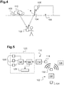
- FIGS 1 and 4 show possible contexts in which the invention may be used. The invention is however not limited to these possible contexts.
- a vehicle 8; 108 is about to enter a park area 5; 105 (here a garage) secured by an access system 4; 104 (here a garage door).
- a mechanism 6; 66; 106 for operating the access system 4; 104 can be remotely controlled, i.e. operated when receiving a wireless instruction provided it has received valid credentials.
- the vehicle 8; 108 is equipped with an automatic parking unit 20; 120 capable of maneuvering the vehicle 8; 108 into the park area 5; 105 provided a user action is (continuously) detected on an electronic device 2; 102, here the user's smartphone.
- the operation of the access system 4; 104 (here the opening of the garage door) is triggered, preferably synchronously to the vehicle maneuver, either by a module 12; 52 of the vehicle onboard system 10 ( Figure 1 ) or by a module 130 of the electronic device 102 ( Figure 4 ).
- the vehicle onboard system 10 comprises the automatic parking unit 20, an electronic control module 12 and a data communication circuit 14.
- the data communication circuit 14 is suited to establish a wireless data link with the mechanism 6 for operating the access system 4.
- this wireless data link is for instance a Bluetooth data link or a data link in a wireless local area network (WLAN).
- WLAN wireless local area network
- the electronic device 2 (here a smartphone as already mentioned) comprises a control unit 30 (such as a microcontroller), a data communication circuit 32 and a human-machine interface (HMI) or user interface 34 (here a touch screen).
- a control unit 30 such as a microcontroller
- a data communication circuit 32 and a human-machine interface (HMI) or user interface 34 (here a touch screen).
- HMI human-machine interface
- user interface 34 here a touch screen
- the data communication circuit 32 of the electronic device 2 and the data communication circuit 14 in the vehicle 8 can establish a wireless communication, here of the same type as the wireless data link between the data communication circuit 4 and the mechanism 6 (i.e. a Bluetooth data link or a data link in a WLAN).
- a wireless communication here of the same type as the wireless data link between the data communication circuit 4 and the mechanism 6 (i.e. a Bluetooth data link or a data link in a WLAN).
- the wireless communication and the wireless data link may be of different types (then likely involving several communication circuits in the vehicle 8).
- control unit 30 When the control unit 30 detects a user action on the user interface 34 (e. g. a predefined user action requested to the user by an appropriate HMI on the user interface 34), the control unit 30 instructs the data communication circuit 32 to send data confirming detection of this pre-defined user action to the data communication circuit 14 of the vehicle 8 (via the wireless communication established between the data communication circuit 14 of the vehicle 8 and the data communication circuit 32 of the electronic device 30).
- a user action on the user interface 34 e. g. a predefined user action requested to the user by an appropriate HMI on the user interface 34
- the control unit 30 instructs the data communication circuit 32 to send data confirming detection of this pre-defined user action to the data communication circuit 14 of the vehicle 8 (via the wireless communication established between the data communication circuit 14 of the vehicle 8 and the data communication circuit 32 of the electronic device 30).
- the electronic control module 12 can thus receive these data via the data communication circuit 14.
- the electronic control module 12 commands and/or monitors said maneuver by transmitting a corresponding instruction to the automatic parking unit 20.
- the electronic control module 12 would no longer receive the data confirming the user action and would then instruct the automatic parking unit 20 to stop the maneuver.
- the electronic control module 12 instructs the data communication circuit 14 to send a wireless instruction to the mechanism 6 together with valid credentials (via the data link established between the data communication circuit 14 and the mechanism 6) to operate the access system 4.
- the transmission of the wireless instruction by the data communication circuit 14 may be precisely synchronized with the maneuver.
- the automatic parking unit 20 may for instance be suited to compute an appropriate time to operate the access system 4 (possibly taking into account the time needed to operate the access system 4) and to communicate said appropriate time to the electronic control module 12 such that the electronic control module 12 may control operation of the access system 4 at said appropriate time.
- the access system 4 is here a garage door.
- the access system could be an elevator making it possible for the vehicle to access the park area. It could also be an area closed by a gate or barrier.
- the electronic control module 12 also commands the data communication circuit 14 to send an instruction to control a comfort equipment (e.g. a garage light) associated with the access system.
- a comfort equipment e.g. a garage light
- the mechanism 6 operates the access system 4 (i.e. here opens the garage door) to allow the vehicle 8 entering the park area 5 (here the garage).
- the electronic control module 12 can then further command and monitor the automatic parking unit 20 to drive the vehicle 8, passing the cleared access system 4 and into the park area 5.
- the electronic control module 12 may instruct the data communication circuit 14 to send a wireless instruction to the mechanism 6 in order to close the access system 4.
- the closure of the access system may be initiated by the GDO itself following a timeout (time elapsed within any received instructions to keep the access system open).
- Figure 3 shows an alternative arrangement usable in the context of Figure 1 .
- the vehicle onboard system comprises the automatic parking unit 20, an electronic control module 52, a data communication circuit 54, a button 56 and a radio communication circuit 58.
- the button 56 and the radio communication circuit 58 are connected via a bus 40.
- an actuation instruction is transmitted on the bus 40.
- the radio communication circuit 58 Upon detecting this actuation instruction on the bus 40, the radio communication circuit 58 generates a sub GHz radiofrequency signal (i.e. a radiofrequency signal having a main frequency below 1 GHz) intended to the mechanism 66 (and corresponding to the wireless instruction and credentials mentioned above).
- the mechanism 66 is designed to operate the access system 4 (here to open the garage door) when receiving the radiofrequency signal with correct credentials.
- the electronic device 2 (which is for instance a smartphone) comprises a control unit 30 (such as a microcontroller), a data communication circuit 32 and a human-machine interface (HMI) or user interface 34 (here a touch screen).
- a control unit 30 such as a microcontroller
- a data communication circuit 32 and a human-machine interface (HMI) or user interface 34 (here a touch screen).
- HMI human-machine interface
- user interface 34 here a touch screen
- the data communication circuit 32 of the electronic device 2 and the data communication circuit 54 in the vehicle can establish a wireless communication, for instance a Bluetooth communication or a communication in a wireless local area network (WLAN).
- a wireless communication for instance a Bluetooth communication or a communication in a wireless local area network (WLAN).
- WLAN wireless local area network
- control unit 30 When the control unit 30 detects a pre-defined user action on the user interface 34, the control unit 30 instructs the data communication circuit 32 to send data confirming detection of this pre-defined user action to the data communication circuit 14 of the vehicle.
- the electronic control module 52 can thus receive these data via the data communication circuit 54.
- the electronic control module 52 commands and/or monitors said maneuver by transmitting a corresponding instruction to the automatic parking unit 20.
- the electronic control module 52 transmits the actuation instruction (identical to the instruction provided by button 56 upon being depressed) on the bus 40, which actuation is received by the radio communication circuit 58.
- the radio communication circuit 58 thus emits the radiofrequency signal, which results, as explained above, in the mechanism 66 operating the access system 4 (here opening the garage door), making it possible for the vehicle to clear the access system 4.
- the transmission of the radiofrequency signal by the radio communication circuit 58 may be precisely synchronized with the maneuver.
- the automatic parking unit 20 may for instance be suited to compute an appropriate time to operate the access system 4 (possibly taking into account the time needed to operate the access system 4) and to communicate said appropriate time to the electronic control module 52 such that the electronic control module 52 may control operation of the access system 4 (by transmitting the actuation instruction on the bus 40) at said appropriate time.
- a conventional mechanism 66 triggered by a sub Ghz radiofrequency signal can be activated synchronously while the automatic parking maneuver is taking place.
- Figure 5 shows another possible embodiment in the context of Figure 4 .
- the vehicle onboard system 110 comprises the automatic parking unit 120, an electronic control unit 112 and a data communication circuit 114.
- the electronic device 102 (e.g. a smartphone) comprises a control module 130 (such as a microcontroller), a data communication circuit 132 and a human-machine interface (HMI) 134 (here a touch screen).
- a control module 130 such as a microcontroller
- a data communication circuit 132 such as a Wi-Fi connection
- a human-machine interface (HMI) 134 here a touch screen
- the data communication circuit 132 of the electronic device 102 and the data communication circuit 114 of the vehicle 108 can establish a wireless communication (for instance a Bluetooth communication or a communication in a WLAN).
- a wireless communication for instance a Bluetooth communication or a communication in a WLAN.
- the data communication circuit 132 of the electronic device 102 is also suited to establish a wireless data link with the mechanism 106 for operating the access system 104.
- this wireless data link is for instance a Bluetooth data link or a data link in a wireless local area network (WLAN).
- WLAN wireless local area network
- the wireless data link between the data communication circuit 132 and the mechanism 106 is of the same type as the wireless communication between the data communication circuit 132 of the electronic device 102 and the data communication circuit 114 of the vehicle 108.
- the wireless communication and the wireless data link may be of different types (then likely involving several communication circuits of the electronic device 102).
- the control module 130 is suited to detect a user action on the user interface 134 (e.g. a predefined user action requested to the user by an appropriate display on the user interface 134) and, as long as such a user action is detected, to send a continuation instruction to the electronic control unit 112 (via the wireless communication established between data communication circuit 114 and data communication circuit 132 as explained above) to confirm the vehicle maneuver may safely proceed further.
- a user action on the user interface 134 e.g. a predefined user action requested to the user by an appropriate display on the user interface 134
- a continuation instruction to the electronic control unit 112 (via the wireless communication established between data communication circuit 114 and data communication circuit 132 as explained above) to confirm the vehicle maneuver may safely proceed further.
- the electronic control unit 112 commands the automatic parking unit 120 to carry on with the maneuver, as explained below.
- the control module 130 sends a wireless instruction to the mechanism 106 via the wireless data link established between the data communication circuit 132 of the electronic device 102 and the mechanism 106. Operation of the access system may thus be controlled synchronously to the vehicle maneuver. The decision to trigger the access system operation may also be taken asynchronously (relative to the progress of the maneuver), for instance at the start of the maneuver or when the maneuver cannot proceed any longer without the access system to be operated.
- the mechanism 106 Upon receiving the wireless instruction and correct credentials, the mechanism 106 operates (here opens) the access system 104 (here the garage door) such that, under the control of the automatic parking unit 120, the vehicle 108 may clear the access system 104 and continue the maneuver (here: enter the park area 105).
- control module 130 also commands the data communication circuit 132 to send an instruction to control a comfort equipment (e.g. a garage lighting) associated or independent to the access system 104.
- a comfort equipment e.g. a garage lighting
- the electronic control unit 112 instructs the automatic parking unit 120 to stop the maneuver.
- the automatic parking unit 20, 120 comprises at least one sensor 26; 126 (generally a plurality of sensors), a processing circuit 24; 124, a control circuit 22; 122 and at least a vehicle motion control mechanism 28; 128 (such as a power train and/or a steering system and/or a braking system).
- Each sensor 26; 126 (for instance a video camera or an ultrasonic sensor) captures data representative of the environment of the vehicle 8; 108.
- the processing circuit 24; 124 processes (e.g. analyzes) the (raw) data captured by the sensor(s) 26; 126 to generate processed data, which also incorporates the vehicle 8; 108 environment, but in a more synthetic manner.
- the processed data contains for instance the location of detected objects in the environment of the vehicle 8; 108.
- the control circuit 22; 122 receives these processed data and a command from the electronic control module or unit 12; 52; 112.
- the control circuit 22; 122 controls the vehicle motion control mechanism(s) 28; 128 based on the processed data so as to drive the vehicle 8; 108 in its environment.
- the control circuit 22; 122 controls the vehicle motion control mechanism(s) 28; 128 to halt the vehicle 8; 108.
Landscapes
- Engineering & Computer Science (AREA)
- Mechanical Engineering (AREA)
- Transportation (AREA)
- Chemical & Material Sciences (AREA)
- Automation & Control Theory (AREA)
- Computer Networks & Wireless Communication (AREA)
- Combustion & Propulsion (AREA)
- Medical Informatics (AREA)
- Signal Processing (AREA)
- Health & Medical Sciences (AREA)
- General Health & Medical Sciences (AREA)
- Computing Systems (AREA)
- Human Computer Interaction (AREA)
- Physics & Mathematics (AREA)
- General Physics & Mathematics (AREA)
- Selective Calling Equipment (AREA)
- Control Of Driving Devices And Active Controlling Of Vehicle (AREA)
- Control Of Position, Course, Altitude, Or Attitude Of Moving Bodies (AREA)
Abstract
Description
- The invention relates to vehicles having an automatic maneuver capability and more precisely to a device aimed at controlling a maneuver of a vehicle.
- It is known to provide vehicles with an automatic parking capability, such as described for instance in the patent application published as
WO 2016/185 151 . - Nowadays, the automatic parking function are usually performed under the supervision of the driver, located outside the vehicle, controlling the maneuver execution using a remote control device that may be his Smartphone.
- Besides, in many regions around the world, it is quite common to possess a garage that is accessible through a remote controlled door. Another remote control device is usually provided to trigger the opening of a garage door or a gate. Such access systems are generally known as GDO (for "Garage Door Opener") and the devices remotely controlling them UGDO (for "Universal Garage Door Opener").
- In this context, the invention provides a single device for controlling a maneuver of a vehicle in or out of a park area secured by a remotely controlled access system, said device comprising a module suited to monitor said maneuver as long as a user action is detected on an electronic device and to control the operation (i.e. for example to trigger the opening) of the access system.
- Thanks to the use of this module, the automatic maneuver and the operation of the access system can be managed consistently, without the need of separate user inputs to trigger each system.
- For clarity, the access system may be for instance a garage door, a gate, a barrier or a lift, that needs to be operated while maneuvering the car.
- The following optional (and thus not exhaustive) features are also proposed:
- the module is suited to control operation of the access system (e.g. to control the movements of the garage door) by instructing a communication circuit to transmit a wireless instruction (in practice: together with access credentials) to a mechanism for operating the access system (in practice: to a dedicated receiver that controls in turn the mechanism of the access system);
- the communication circuit is suited to establish a wireless data link with said mechanism and to transmit said wireless instruction via said wireless data link;
- the communication circuit is suited to transmit the wireless instruction by generating a sub GHz radiofrequency signal;
- the vehicle includes a button suited to send a given instruction via a bus to the communication circuit;
- the communication circuit generates said radiofrequency signal upon receiving the given instruction;
- the module is also suited to send the given instruction to the communication circuit via the bus;
- the module is suited to receive data confirming the detection of the user action via a wireless communication established with the electronic device;
- the module is embedded in the electronic device;
- the module is suited to detect the user action via a user interface of the electronic device;
- the module is suited to control said maneuver by sending a corresponding instruction to an electronic control unit inside the vehicle;
- the maneuver is performed by an automatic parking unit controlled by said module;
- the automatic parking unit includes at least one sensor for capturing data related to the vehicle environment;
- the automatic parking unit includes a processing circuit for processing data captured by the sensor;
- the automatic parking unit includes a control circuit for controlling a vehicle motion control mechanism based on the processed data;
- the automatic parking unit is suited to compute an appropriate time to operate the access system;
- the automatic parking unit is suited to communicate said appropriate time to the module such that the module may control operation of the access system at said appropriate time;
- said module is suited to control a remotely controlled comfort equipment (such as lighting) that is conveniently operated during the vehicle maneuver;
- said module is suited to control the access system to close after the maneuver is completed.
- Other features and advantages of the embodiments of the present invention will be better understood upon reading of preferred embodiments thereof with reference to the appended drawings.
-
-
Figure 1 represents the possible context of a first embodiment of the invention. -
Figure 2 schematically shows elements used in this first embodiment. -
Figure 3 schematically shows elements used in a possible variation of this first embodiment. -
Figure 4 represents the possible context of a second embodiment of the invention. -
Figure 5 schematically shows elements used in this second embodiment. -
Figures 1 and4 show possible contexts in which the invention may be used. The invention is however not limited to these possible contexts. - In these contexts, a
vehicle 8; 108 is about to enter apark area 5; 105 (here a garage) secured by anaccess system 4; 104 (here a garage door). - A
mechanism 6; 66; 106 for operating theaccess system 4; 104 (here for opening or closing the garage door) can be remotely controlled, i.e. operated when receiving a wireless instruction provided it has received valid credentials. - The
vehicle 8; 108 is equipped with anautomatic parking unit 20; 120 capable of maneuvering thevehicle 8; 108 into thepark area 5; 105 provided a user action is (continuously) detected on anelectronic device 2; 102, here the user's smartphone. - The operation of the
access system 4; 104 (here the opening of the garage door) is triggered, preferably synchronously to the vehicle maneuver, either by amodule 12; 52 of the vehicle onboard system 10 (Figure 1 ) or by amodule 130 of the electronic device 102 (Figure 4 ). - According to a first embodiment schematically represented in
Figure 2 and usable in the context ofFigure 1 , the vehicle onboardsystem 10 comprises theautomatic parking unit 20, anelectronic control module 12 and adata communication circuit 14. - The
data communication circuit 14 is suited to establish a wireless data link with themechanism 6 for operating theaccess system 4. In practice, this wireless data link is for instance a Bluetooth data link or a data link in a wireless local area network (WLAN). - The electronic device 2 (here a smartphone as already mentioned) comprises a control unit 30 (such as a microcontroller), a
data communication circuit 32 and a human-machine interface (HMI) or user interface 34 (here a touch screen). - The
data communication circuit 32 of theelectronic device 2 and thedata communication circuit 14 in thevehicle 8 can establish a wireless communication, here of the same type as the wireless data link between thedata communication circuit 4 and the mechanism 6 (i.e. a Bluetooth data link or a data link in a WLAN). As a possible variation, the wireless communication and the wireless data link may be of different types (then likely involving several communication circuits in the vehicle 8). - When the
control unit 30 detects a user action on the user interface 34 (e. g. a predefined user action requested to the user by an appropriate HMI on the user interface 34), thecontrol unit 30 instructs thedata communication circuit 32 to send data confirming detection of this pre-defined user action to thedata communication circuit 14 of the vehicle 8 (via the wireless communication established between thedata communication circuit 14 of thevehicle 8 and thedata communication circuit 32 of the electronic device 30). - The
electronic control module 12 can thus receive these data via thedata communication circuit 14. - As long as a user action is detected on the electronic device 2 (i.e. as long as the
electronic control module 12 receives the data confirming user action), theelectronic control module 12 commands and/or monitors said maneuver by transmitting a corresponding instruction to theautomatic parking unit 20. - Should however the user fail to perform the predefined user action on the user interface 34, the
electronic control module 12 would no longer receive the data confirming the user action and would then instruct theautomatic parking unit 20 to stop the maneuver. - Back to the situation where the user continuously interacts with the user interface 34 of the
electronic device 2, at a point of time during the vehicle maneuver (i.e. synchronously to the maneuver), theelectronic control module 12 instructs thedata communication circuit 14 to send a wireless instruction to themechanism 6 together with valid credentials (via the data link established between thedata communication circuit 14 and the mechanism 6) to operate theaccess system 4. - The transmission of the wireless instruction by the
data communication circuit 14 may be precisely synchronized with the maneuver. In this goal, theautomatic parking unit 20 may for instance be suited to compute an appropriate time to operate the access system 4 (possibly taking into account the time needed to operate the access system 4) and to communicate said appropriate time to theelectronic control module 12 such that theelectronic control module 12 may control operation of theaccess system 4 at said appropriate time. - As already mentioned, the
access system 4 is here a garage door. According to a possible variation, the access system could be an elevator making it possible for the vehicle to access the park area. It could also be an area closed by a gate or barrier. - In addition, according to a possible embodiment, the
electronic control module 12 also commands thedata communication circuit 14 to send an instruction to control a comfort equipment (e.g. a garage light) associated with the access system. - As a result of the wireless instruction received from the
onboard system 10 of thevehicle 8, themechanism 6 operates the access system 4 (i.e. here opens the garage door) to allow thevehicle 8 entering the park area 5 (here the garage). - The
electronic control module 12 can then further command and monitor theautomatic parking unit 20 to drive thevehicle 8, passing thecleared access system 4 and into thepark area 5. - Once inside the
park area 5, with the vehicle maneuver completed and the vehicle safely parked (engine is off), theelectronic control module 12 may instruct thedata communication circuit 14 to send a wireless instruction to themechanism 6 in order to close theaccess system 4. For existing GDO, the closure of the access system may be initiated by the GDO itself following a timeout (time elapsed within any received instructions to keep the access system open). -
Figure 3 shows an alternative arrangement usable in the context ofFigure 1 . - According to this possible solution, the vehicle onboard system comprises the
automatic parking unit 20, anelectronic control module 52, adata communication circuit 54, abutton 56 and aradio communication circuit 58. - The
button 56 and theradio communication circuit 58 are connected via abus 40. When the user depresses thebutton 56, an actuation instruction is transmitted on thebus 40. Upon detecting this actuation instruction on thebus 40, theradio communication circuit 58 generates a sub GHz radiofrequency signal (i.e. a radiofrequency signal having a main frequency below 1 GHz) intended to the mechanism 66 (and corresponding to the wireless instruction and credentials mentioned above). - The
mechanism 66 is designed to operate the access system 4 (here to open the garage door) when receiving the radiofrequency signal with correct credentials. - Thus, activation of the
button 56 by the user leads to operating theaccess system 4 of thepark area 5. - The electronic device 2 (which is for instance a smartphone) comprises a control unit 30 (such as a microcontroller), a
data communication circuit 32 and a human-machine interface (HMI) or user interface 34 (here a touch screen). - The
data communication circuit 32 of theelectronic device 2 and thedata communication circuit 54 in the vehicle can establish a wireless communication, for instance a Bluetooth communication or a communication in a wireless local area network (WLAN). - When the
control unit 30 detects a pre-defined user action on the user interface 34, thecontrol unit 30 instructs thedata communication circuit 32 to send data confirming detection of this pre-defined user action to thedata communication circuit 14 of the vehicle. - The
electronic control module 52 can thus receive these data via thedata communication circuit 54. - As long as a user action is detected on the electronic device 2 (i.e. as long as the
electronic control module 52 receives the data confirming user action), theelectronic control module 52 commands and/or monitors said maneuver by transmitting a corresponding instruction to theautomatic parking unit 20. - At a point in time during the maneuver (i.e. synchronously to the maneuver), the
electronic control module 52 transmits the actuation instruction (identical to the instruction provided bybutton 56 upon being depressed) on thebus 40, which actuation is received by theradio communication circuit 58. Theradio communication circuit 58 thus emits the radiofrequency signal, which results, as explained above, in themechanism 66 operating the access system 4 (here opening the garage door), making it possible for the vehicle to clear theaccess system 4. - The transmission of the radiofrequency signal by the
radio communication circuit 58 may be precisely synchronized with the maneuver. In this goal, theautomatic parking unit 20 may for instance be suited to compute an appropriate time to operate the access system 4 (possibly taking into account the time needed to operate the access system 4) and to communicate said appropriate time to theelectronic control module 52 such that theelectronic control module 52 may control operation of the access system 4 (by transmitting the actuation instruction on the bus 40) at said appropriate time. - Thus, a
conventional mechanism 66 triggered by a sub Ghz radiofrequency signal can be activated synchronously while the automatic parking maneuver is taking place. -
Figure 5 shows another possible embodiment in the context ofFigure 4 . - According to this embodiment, the vehicle
onboard system 110 comprises theautomatic parking unit 120, anelectronic control unit 112 and adata communication circuit 114. - The electronic device 102 (e.g. a smartphone) comprises a control module 130 (such as a microcontroller), a
data communication circuit 132 and a human-machine interface (HMI) 134 (here a touch screen). - The
data communication circuit 132 of theelectronic device 102 and thedata communication circuit 114 of thevehicle 108 can establish a wireless communication (for instance a Bluetooth communication or a communication in a WLAN). - The
data communication circuit 132 of theelectronic device 102 is also suited to establish a wireless data link with themechanism 106 for operating theaccess system 104. In practice, this wireless data link is for instance a Bluetooth data link or a data link in a wireless local area network (WLAN). - In the example described here, the wireless data link between the
data communication circuit 132 and themechanism 106 is of the same type as the wireless communication between thedata communication circuit 132 of theelectronic device 102 and thedata communication circuit 114 of thevehicle 108. As a possible variation, the wireless communication and the wireless data link may be of different types (then likely involving several communication circuits of the electronic device 102). - The
control module 130 is suited to detect a user action on the user interface 134 (e.g. a predefined user action requested to the user by an appropriate display on the user interface 134) and, as long as such a user action is detected, to send a continuation instruction to the electronic control unit 112 (via the wireless communication established betweendata communication circuit 114 anddata communication circuit 132 as explained above) to confirm the vehicle maneuver may safely proceed further. - Precisely, when the
electronic control unit 112 receives the continuation instruction, theelectronic control unit 112 commands theautomatic parking unit 120 to carry on with the maneuver, as explained below. - At some point of time during the maneuver, when the
automatic parking unit 120 computes that the operating of the access system needs to be started to allow a continuous park maneuver, thecontrol module 130 sends a wireless instruction to themechanism 106 via the wireless data link established between thedata communication circuit 132 of theelectronic device 102 and themechanism 106. Operation of the access system may thus be controlled synchronously to the vehicle maneuver. The decision to trigger the access system operation may also be taken asynchronously (relative to the progress of the maneuver), for instance at the start of the maneuver or when the maneuver cannot proceed any longer without the access system to be operated. - Upon receiving the wireless instruction and correct credentials, the
mechanism 106 operates (here opens) the access system 104 (here the garage door) such that, under the control of theautomatic parking unit 120, thevehicle 108 may clear theaccess system 104 and continue the maneuver (here: enter the park area 105). - In addition, according to a possible embodiment, the
control module 130 also commands thedata communication circuit 132 to send an instruction to control a comfort equipment (e.g. a garage lighting) associated or independent to theaccess system 104. - At any time, if the
electronic control unit 112 fails to receive the continuation instruction for a predetermined period of time (possibly because the user action is no longer detected on theuser interface 134 and thecontrol module 130 has thus stopped sending the continuation instruction), theelectronic control unit 112 instructs theautomatic parking unit 120 to stop the maneuver. - Operation of the
automatic parking unit - The
automatic parking unit sensor 26; 126 (generally a plurality of sensors), aprocessing circuit 24; 124, acontrol circuit 22; 122 and at least a vehiclemotion control mechanism 28; 128 (such as a power train and/or a steering system and/or a braking system). - Each
sensor 26; 126 (for instance a video camera or an ultrasonic sensor) captures data representative of the environment of thevehicle 8; 108. - The
processing circuit 24; 124 processes (e.g. analyzes) the (raw) data captured by the sensor(s) 26; 126 to generate processed data, which also incorporates thevehicle 8; 108 environment, but in a more synthetic manner. The processed data contains for instance the location of detected objects in the environment of thevehicle 8; 108. - The
control circuit 22; 122 receives these processed data and a command from the electronic control module orunit 12; 52; 112. - When the command received from the electronic control module or
unit 12; 52; 112 indicates the automatic maneuver should proceed, thecontrol circuit 22; 122 controls the vehicle motion control mechanism(s) 28; 128 based on the processed data so as to drive thevehicle 8; 108 in its environment. - When the command received from the electronic control module or
unit 12; 52; 112 indicates the automatic maneuver should be stopped, thecontrol circuit 22; 122 controls the vehicle motion control mechanism(s) 28; 128 to halt thevehicle 8; 108. - The examples described here involve a vehicle entering into a park area. The invention is however not limited to this situation and also applies in particular to the case of a vehicle maneuvering out of a park area.
Claims (12)
- A device for controlling a maneuver of a vehicle (8; 108) in or out of a park area (5; 105) secured by a remotely controlled access system (4; 104), said device comprising a module (12; 52; 130) suited to monitor said maneuver as long as a user action is detected on an electronic device (2; 102) and to control the operation of the access system (4; 104).
- The device according to claim 1, wherein the module (12; 52; 130) is suited to control the operation of the access system (4; 104) by instructing a communication circuit (14; 58; 132) to transmit a wireless instruction to a mechanism (6; 66; 106) for controlling the access system (4; 104).
- The device according to claim 2, wherein the communication circuit (14; 132) is suited to establish a wireless data link with said mechanism (6; 106) and to transmit said wireless instruction via said wireless data link.
- The device according to claim 2, wherein the communication circuit (58) is suited to transmit the wireless instruction by generating a sub GHz radiofrequency signal.
- The device according to claim 4, wherein the vehicle (8) includes a button (56) suited to send a given instruction via a bus (40) to the communication circuit (58), the communication circuit (58) generating said radiofrequency signal upon receiving the given instruction, and wherein the module (52) is also adapted to send the given instruction to the communication circuit (58) via the bus (40).
- The device according to any of claims 1 to 5, wherein the module (12; 52) is suited to receive data confirming the detection of the user action via a wireless communication established with the electronic device (2).
- The device according to any of claims 1 to 3, wherein the module (130) is embedded in the electronic device (102) and suited to detect the user action via a user interface (134) of the electronic device (102) and to control said maneuver by sending a corresponding instruction to an electronic control unit (112) inside the vehicle (108).
- The device according to any of claims 1 to 7, wherein the maneuver is performed by an automatic parking unit (20; 120) controlled by said module (12; 52; 130).
- The device according to claim 8, wherein the automatic parking unit (20; 120) includes at least one sensor (26; 126) for capturing data related to the vehicle environment, a processing circuit (24; 124) for processing data captured by the sensor (26; 126) and a control circuit (22; 122) for controlling a vehicle motion control mechanism (28; 128) based on the processed data.
- The device according to claim 8 or 9, wherein the automatic parking unit (20; 120) is suited to compute an appropriate time to operate the access system (4; 104).
- The device according to any of claims 1 to 10, wherein said module is suited to control a remotely controlled comfort equipment.
- The device according to any of claims 1 to 11, wherein said module (12) is suited to control the access system (4) to close after the maneuver is completed.
Applications Claiming Priority (1)
| Application Number | Priority Date | Filing Date | Title |
|---|---|---|---|
| CN201710321927.9A CN108868452A (en) | 2017-05-09 | 2017-05-09 | For controlling the device of trailer reversing |
Publications (1)
| Publication Number | Publication Date |
|---|---|
| EP3401179A1 true EP3401179A1 (en) | 2018-11-14 |
Family
ID=62116284
Family Applications (1)
| Application Number | Title | Priority Date | Filing Date |
|---|---|---|---|
| EP18170651.6A Withdrawn EP3401179A1 (en) | 2017-05-09 | 2018-05-03 | A device for controlling a maneuver of a vehicle |
Country Status (2)
| Country | Link |
|---|---|
| EP (1) | EP3401179A1 (en) |
| CN (1) | CN108868452A (en) |
Families Citing this family (1)
| Publication number | Priority date | Publication date | Assignee | Title |
|---|---|---|---|---|
| CN112002050A (en) * | 2020-07-01 | 2020-11-27 | 浙江吉利汽车研究院有限公司 | Vehicle warehouse-out and warehouse-in control method and device, electronic equipment and storage medium |
Citations (2)
| Publication number | Priority date | Publication date | Assignee | Title |
|---|---|---|---|---|
| US20140320263A1 (en) * | 2013-04-26 | 2014-10-30 | GM Global Technology Operations LLC | Methods, program products, and systems relating to vehicular garage door control systems |
| WO2016185151A1 (en) | 2015-05-20 | 2016-11-24 | Valeo Comfort And Driving Assistance | Method for interactive control of the automatic parking of a motor vehicle by means of a mobile terminal |
Family Cites Families (5)
| Publication number | Priority date | Publication date | Assignee | Title |
|---|---|---|---|---|
| US6993246B1 (en) * | 2000-09-15 | 2006-01-31 | Hewlett-Packard Development Company, L.P. | Method and system for correlating data streams |
| DE102015211642B3 (en) * | 2015-06-24 | 2016-09-15 | Volkswagen Aktiengesellschaft | Communication device, control device and system for the vehicle sector |
| EP3365197B1 (en) * | 2015-10-22 | 2022-11-30 | Gentex Corporation | Integrated vehicle communication system and method |
| CN105840041B (en) * | 2016-03-25 | 2017-06-30 | 乐视汽车(北京)有限公司 | Garage door sharing method, system and equipment |
| CN106547228A (en) * | 2016-10-27 | 2017-03-29 | 湖南海翼电子商务股份有限公司 | Garage controlling device for doors and its method |
-
2017
- 2017-05-09 CN CN201710321927.9A patent/CN108868452A/en active Pending
-
2018
- 2018-05-03 EP EP18170651.6A patent/EP3401179A1/en not_active Withdrawn
Patent Citations (2)
| Publication number | Priority date | Publication date | Assignee | Title |
|---|---|---|---|---|
| US20140320263A1 (en) * | 2013-04-26 | 2014-10-30 | GM Global Technology Operations LLC | Methods, program products, and systems relating to vehicular garage door control systems |
| WO2016185151A1 (en) | 2015-05-20 | 2016-11-24 | Valeo Comfort And Driving Assistance | Method for interactive control of the automatic parking of a motor vehicle by means of a mobile terminal |
Non-Patent Citations (7)
| Title |
|---|
| GENTEX CORPORATION: "Homelink by Gentex corporation: compatible manufacturers", 11 March 2016 (2016-03-11), Homelink Manufacturer Homepage, XP055505518, Retrieved from the Internet <URL:https://web.archive.org/web/20160311200353if_/http://homelink.com/assets/downloads/homelink_ukenglish.pdf> [retrieved on 20180907] * |
| GENTEX CORPORATION: "HomeLink Welcome Page", 17 March 2016 (2016-03-17), XP055505840, Retrieved from the Internet <URL:https://web.archive.org/web/20160317101541/https://www.homelink.com/home/welcome> [retrieved on 20180910] * |
| MARK SCHEY: "View Summon From Outside - Tesla Model S P85D", YOUTUBE, 9 January 2016 (2016-01-09), pages 1, XP054978672, Retrieved from the Internet <URL:https://www.youtube.com/watch?v=n7i0ku7Eba8> [retrieved on 20180910] * |
| NICK'S TESLA LIFE: "Nick's Telsa - Auto Park - Parking in my garage every day", YOUTUBE, 5 September 2016 (2016-09-05), pages 1, XP054978674, Retrieved from the Internet <URL:https://www.youtube.com/watch?v=sTRSyo3M5J4> [retrieved on 20180910] * |
| RICCO831: "Tesla Summon Settings and Reverse AutoPark into Garage", YOUTUBE, 9 January 2016 (2016-01-09), pages 1, XP054978673, Retrieved from the Internet <URL:https://www.youtube.com/watch?v=-s40Auc95zs> [retrieved on 20180910] * |
| TESLA: "Model S release notes 7 1 1 us cn", 1 January 2016 (2016-01-01), Manufacturer Homepage, Firmware release notes, XP055505456, Retrieved from the Internet <URL:https://www.tesla.com/sites/default/files/Model_S_release_notes_7_1_1_us_cn.pdf> [retrieved on 20180907] * |
| THE FAQWARE TEAM: ""homelink analysis" | Search Results | TeslaTap", 14 June 2017 (2017-06-14), pages 1 - 3, XP055505903, Retrieved from the Internet <URL:https://teslatap.com/?s="homelink+analysis"> [retrieved on 20180910] * |
Also Published As
| Publication number | Publication date |
|---|---|
| CN108868452A (en) | 2018-11-23 |
Similar Documents
| Publication | Publication Date | Title |
|---|---|---|
| US20180329410A1 (en) | Device for controlling a maneuver of a vehicle | |
| US9886031B2 (en) | Controlling of the automatic driving process of a vehicle | |
| US9896090B2 (en) | Remote parking control system and control method thereof | |
| JP4702613B2 (en) | Vehicle door opening / closing device and vehicle door opening / closing control method | |
| CN107402572A (en) | The continuous user mutual and intention carried out by measuring force change determines | |
| EP3459827B1 (en) | Method and system for automated parking of a vehicle | |
| US11423784B2 (en) | Method for controlling a parking operation of a motor vehicle | |
| US20190025816A1 (en) | Remote control method for a driver assistance system, driver assistance system, and motor vehicle provided therewith | |
| CN112753009A (en) | Man-machine interaction method and man-machine interaction device | |
| US10071707B2 (en) | Elimination of the activatability of a function by a radio on a vehicle | |
| US6863247B2 (en) | Method and apparatus for transmitting signals to a locomotive control device | |
| EP3401179A1 (en) | A device for controlling a maneuver of a vehicle | |
| CN106515619A (en) | One-button vehicle security system | |
| EP3401180B1 (en) | Onboard automatic parking system for a vehicle | |
| US11030838B2 (en) | Onboard system for a vehicle and process for sending a command to a park area access system | |
| US20180326976A1 (en) | Onboard automatic parking system for a vehicle | |
| JP6946817B2 (en) | Vehicle remote control system and method | |
| KR101173624B1 (en) | Device having the capability of opening and closing both door and psd simultaneosly | |
| KR102919550B1 (en) | Parking support method to support automatic parking of vehicles | |
| CN114127512A (en) | Method for determining the position of a portable operating device by means of at least two different position determination methods, and electronic position determination system | |
| KR20060010979A (en) | Remote monitoring and control device of vehicle and its control method | |
| KR20170055039A (en) | System and method for opening/closing power door of vehicle |
Legal Events
| Date | Code | Title | Description |
|---|---|---|---|
| PUAI | Public reference made under article 153(3) epc to a published international application that has entered the european phase |
Free format text: ORIGINAL CODE: 0009012 |
|
| STAA | Information on the status of an ep patent application or granted ep patent |
Free format text: STATUS: THE APPLICATION HAS BEEN PUBLISHED |
|
| AK | Designated contracting states |
Kind code of ref document: A1 Designated state(s): AL AT BE BG CH CY CZ DE DK EE ES FI FR GB GR HR HU IE IS IT LI LT LU LV MC MK MT NL NO PL PT RO RS SE SI SK SM TR |
|
| AX | Request for extension of the european patent |
Extension state: BA ME |
|
| STAA | Information on the status of an ep patent application or granted ep patent |
Free format text: STATUS: REQUEST FOR EXAMINATION WAS MADE |
|
| 17P | Request for examination filed |
Effective date: 20190514 |
|
| RBV | Designated contracting states (corrected) |
Designated state(s): AL AT BE BG CH CY CZ DE DK EE ES FI FR GB GR HR HU IE IS IT LI LT LU LV MC MK MT NL NO PL PT RO RS SE SI SK SM TR |
|
| STAA | Information on the status of an ep patent application or granted ep patent |
Free format text: STATUS: EXAMINATION IS IN PROGRESS |
|
| 17Q | First examination report despatched |
Effective date: 20210726 |
|
| STAA | Information on the status of an ep patent application or granted ep patent |
Free format text: STATUS: THE APPLICATION IS DEEMED TO BE WITHDRAWN |
|
| 18D | Application deemed to be withdrawn |
Effective date: 20220208 |