EP3401161A2 - Road surface drawing system, lighting tool for vehicle and method of road surface drawing - Google Patents
Road surface drawing system, lighting tool for vehicle and method of road surface drawing Download PDFInfo
- Publication number
- EP3401161A2 EP3401161A2 EP18171663.0A EP18171663A EP3401161A2 EP 3401161 A2 EP3401161 A2 EP 3401161A2 EP 18171663 A EP18171663 A EP 18171663A EP 3401161 A2 EP3401161 A2 EP 3401161A2
- Authority
- EP
- European Patent Office
- Prior art keywords
- light
- vehicle
- road surface
- image
- unit
- Prior art date
- Legal status (The legal status is an assumption and is not a legal conclusion. Google has not performed a legal analysis and makes no representation as to the accuracy of the status listed.)
- Granted
Links
Images







Classifications
-
- F—MECHANICAL ENGINEERING; LIGHTING; HEATING; WEAPONS; BLASTING
- F21—LIGHTING
- F21S—NON-PORTABLE LIGHTING DEVICES; SYSTEMS THEREOF; VEHICLE LIGHTING DEVICES SPECIALLY ADAPTED FOR VEHICLE EXTERIORS
- F21S43/00—Signalling devices specially adapted for vehicle exteriors, e.g. brake lamps, direction indicator lights or reversing lights
- F21S43/10—Signalling devices specially adapted for vehicle exteriors, e.g. brake lamps, direction indicator lights or reversing lights characterised by the light source
- F21S43/13—Signalling devices specially adapted for vehicle exteriors, e.g. brake lamps, direction indicator lights or reversing lights characterised by the light source characterised by the type of light source
- F21S43/14—Light emitting diodes [LED]
-
- B—PERFORMING OPERATIONS; TRANSPORTING
- B60—VEHICLES IN GENERAL
- B60Q—ARRANGEMENT OF SIGNALLING OR LIGHTING DEVICES, THE MOUNTING OR SUPPORTING THEREOF OR CIRCUITS THEREFOR, FOR VEHICLES IN GENERAL
- B60Q9/00—Arrangement or adaptation of signal devices not provided for in one of main groups B60Q1/00 - B60Q7/00, e.g. haptic signalling
-
- F—MECHANICAL ENGINEERING; LIGHTING; HEATING; WEAPONS; BLASTING
- F21—LIGHTING
- F21S—NON-PORTABLE LIGHTING DEVICES; SYSTEMS THEREOF; VEHICLE LIGHTING DEVICES SPECIALLY ADAPTED FOR VEHICLE EXTERIORS
- F21S43/00—Signalling devices specially adapted for vehicle exteriors, e.g. brake lamps, direction indicator lights or reversing lights
- F21S43/20—Signalling devices specially adapted for vehicle exteriors, e.g. brake lamps, direction indicator lights or reversing lights characterised by refractors, transparent cover plates, light guides or filters
- F21S43/26—Refractors, transparent cover plates, light guides or filters not provided in groups F21S43/235 - F21S43/255
-
- F—MECHANICAL ENGINEERING; LIGHTING; HEATING; WEAPONS; BLASTING
- F21—LIGHTING
- F21S—NON-PORTABLE LIGHTING DEVICES; SYSTEMS THEREOF; VEHICLE LIGHTING DEVICES SPECIALLY ADAPTED FOR VEHICLE EXTERIORS
- F21S43/00—Signalling devices specially adapted for vehicle exteriors, e.g. brake lamps, direction indicator lights or reversing lights
- F21S43/30—Signalling devices specially adapted for vehicle exteriors, e.g. brake lamps, direction indicator lights or reversing lights characterised by reflectors
- F21S43/31—Optical layout thereof
-
- F—MECHANICAL ENGINEERING; LIGHTING; HEATING; WEAPONS; BLASTING
- F21—LIGHTING
- F21W—INDEXING SCHEME ASSOCIATED WITH SUBCLASSES F21K, F21L, F21S and F21V, RELATING TO USES OR APPLICATIONS OF LIGHTING DEVICES OR SYSTEMS
- F21W2103/00—Exterior vehicle lighting devices for signalling purposes
- F21W2103/60—Projection of signs from lighting devices, e.g. symbols or information being projected onto the road
-
- F—MECHANICAL ENGINEERING; LIGHTING; HEATING; WEAPONS; BLASTING
- F21—LIGHTING
- F21Y—INDEXING SCHEME ASSOCIATED WITH SUBCLASSES F21K, F21L, F21S and F21V, RELATING TO THE FORM OR THE KIND OF THE LIGHT SOURCES OR OF THE COLOUR OF THE LIGHT EMITTED
- F21Y2113/00—Combination of light sources
- F21Y2113/10—Combination of light sources of different colours
- F21Y2113/13—Combination of light sources of different colours comprising an assembly of point-like light sources
Definitions
- the present invention relates to a road surface drawing system, a lighting tool for a vehicle and a method of road surface drawing.
- Japanese Unexamined Patent Application, First Publication No. 2015-153057 discloses a driving support apparatus for projecting a support pattern that performs a warning notice related to a vehicle speed or a suitable steering with respect to a driver on a road surface in front of an own vehicle according to road information and a traveling state.
- a lighting tool for a vehicle configured to display an image that shows information on a road surface using contrast of light is proposed as a lighting tool for a vehicle.
- a lighting tool for a vehicle disclosed in Japanese Patent No. 4059079 information formed by a reflection type digital light deflection apparatus is displayed on a road surface.
- a driver changes a position of a viewpoint to which she or he is paying attention according to a vehicle speed. That is, a driver pays attention to the distance of a vehicle when the vehicle travels at a high speed and pays attention to the vicinity of the vehicle when the vehicle travels at a low speed. Focusing on this point, the inventors have conceived to change a display position of an image for a warning notice according to a speed of the vehicle.
- An aspect of the present invention is to provide a road surface drawing system in which an effect of a warning notice to a driver is increased by varying a display position of an image according to a speed of a vehicle.
- Another aspect of the present invention is to provide a lighting tool for a vehicle and road surface drawing system capable of making illuminance on a road surface substantially uniform while minimizing a decrease in efficiency of utilization of light.
- a road surface drawing system of an aspect of the present invention is a road surface drawing system mounted on a vehicle and configured to draw a predetermined image on a road surface in front of the vehicle, the road surface drawing system including: a traveling path drawing unit configured to radiate light and draw the image on the road surface; a vehicle speed detecting unit configured to detect a speed of the vehicle; and a control unit configured to control the traveling path drawing unit, wherein the traveling path drawing unit has a light source unit, an image generating unit configured to modulate light emitted from the light source unit and to form the image, and a projecting unit configured to project the light including the image to the road surface, and the control unit is configured to change a distance between the image and the vehicle on the basis of the detection result of the vehicle speed detecting unit.
- the road surface drawing system can cause the position of the image displayed on the road surface based on the detection result of the vehicle detecting unit to approach or move away from the vehicle. Accordingly, the image can be displayed on a place that is easily recognized by a driver and an effect of a warning notice by the image can be increased by displaying the image on the road surface on the far side of the vehicle when the speed of the vehicle is high and displaying the image on the road surface on the near side of the vehicle when the speed of the vehicle is low.
- the light source unit may include a plurality of light sources, the plurality of light sources may form a plurality of light distribution regions that are aligned on the road surface from a near side of the vehicle toward a far side of the vehicle, respectively, and the control unit may be configured to switch a light emitting state of at least one of the light sources on the basis of the detection result of the vehicle speed detecting unit.
- the light source unit includes the plurality of light sources corresponding to the plurality of light distribution regions arranged from the side near the vehicle toward the side far from the vehicle. For this reason, the light distribution region on the road surface can be varied in the forward/rearward direction of the vehicle by switching the light emitting states of the plurality of light sources. Accordingly, it is possible to change the position of the image displayed on the road surface to approach or move away from the vehicle. As such switching of the light emitting states of the light sources is performed according to the detection result of the vehicle speed detecting unit, the image can be displayed on the place that is easily recognized by a driver, and an effect of a warning notice by the image can be increased.
- control unit may include a light emitting volume control part configured to individually vary light emitting volumes of the plurality of light sources, and the light emitting volume control part may be configured to control a light emitting volume of a light source that forms a light distribution region at the far side of the vehicle among the plurality of light sources to be larger than a light emitting volume of a light source that forms a light distribution region at the near side of the vehicle.
- the light emitting volumes of the plurality of light sources are controlled by the light emitting volume control part. Accordingly, illuminance on the road surface can be adjusted at each of the plurality of light distribution regions formed on the road surface.
- the light emitting volume of the light source that illuminates the light distribution region disposed at the far side of the vehicle among the plurality of light distribution regions formed on the road surface can be increased, and illuminance in the image can be substantially uniform.
- the projecting unit may include a light condensing optical system configured to condense the light including the image generated by the image generating unit and to cause the light to enter the projecting unit, and a reflecting surface configured to reflect the light condensed by the light condensing optical system and project the reflected light to the road surface, and the reflecting surface may have a curvature that is gradually increased from a rear side in a projecting direction toward a front side in the projecting direction.
- the reflecting surface is the curved convex surface or the curved concave surface, in comparison with the region in which light is reflected toward the side far from the vehicle, the light can be reflected by the region in which the light is reflected toward the side near the vehicle, and thereby, it is possible to minimize out of focus of the imaged image by making the distance between the region in which the light is reflected by the reflecting surface and the region in which an image is imaged on the road surface, which is an image plane, can be reduced. Accordingly, it is possible to provide the road surface drawing system capable of clearly displaying the image on the road surface.
- the projecting unit may include a plurality of reflecting surfaces configured to project light to regions having different distances from the vehicle, respectively, and a switching unit configured to select and switch the reflecting surface to any one of the plurality of reflecting surfaces.
- the image can be clearly displayed at the different distances on the road surface by the reflecting surfaces. Accordingly, it is possible to change the position of the image displayed on the road surface to approach or move away from the vehicle. As such switching of the light emitting state of the light source is performed according to the detection result of the vehicle speed detecting unit, an effect of a warning notice by the image can be increased by displaying the image on the place that is easily recognized by a driver.
- the traveling path drawing unit may form a light distribution pattern as a headlight for a vehicle while displaying the image that emphasizes the traveling path on the road surface.
- the traveling path drawing unit is also used as the headlight for a vehicle, the entire apparatus can be minimized in size in comparison with the case in which the traveling path drawing unit and the headlight for a vehicle are individually installed.
- the image generating unit may be configured to switch a light distribution pattern generated state in which a light distribution pattern is generated as the headlight for a vehicle and a traveling path emphasized state in which the image that emphasizes the traveling path is generated, at a high speed
- the light source unit may be configured to cause white light to enter the image generating unit in the light distribution pattern generated state and to cause visible light having a color different from the white light to enter the image generating unit in the traveling path emphasized state.
- the road surface drawing system can display the image of the traveling path that prompts a warning notice to a driver with visible light having a color different from white light while forming a light distribution pattern as the headlight for a vehicle using the white light.
- the road surface drawing system may include a traveling path recognition unit configured to detect road conditions in front of the vehicle, wherein the control unit may be configured to reflect the recognized result of the traveling path recognition unit to the image.
- the configuration it is possible to clearly notify the driver whether the vehicle can be driven by judging the state of the traveling path based on the road conditions acquired by the traveling path recognition unit.
- the road conditions acquired from the traveling path recognition unit include a traffic lane, a curbstone, a state of a rut, or the like, on the road surface.
- the road surface drawing system may include a traveling path information acquisition unit configured to acquire road conditions in front of the vehicle from outside, wherein the control unit may be configured to reflect information acquired by the traveling path information acquisition unit to the image.
- the road conditions acquired from the outside include information acquired from a global positioning system (GPS), a vehicle information and communication system (VICS, a registered trade mark).
- GPS global positioning system
- VICS vehicle information and communication system
- a lighting tool for a vehicle of another aspect of the present invention is a lighting tool for a vehicle configured to radiate light toward a road surface from a vehicle, the lighting tool for a vehicle including: a plurality of light sources arranged in a direction perpendicular to a widthwise direction of the vehicle; a light emitting volume control part configured to individually vary light emitting volumes of the plurality of light sources; an image generating unit configured to modulate light emitted from the light source and to form an image; and a projecting unit configured to project light including the image to the road surface, wherein the plurality of light sources are configured to form a plurality of light distribution regions that are aligned on the road surface from a near side of the vehicle toward a far side of the vehicle, respectively, and the projecting unit is configured to radiate the image in the plurality of light distribution regions.
- the plurality of light sources corresponding to the plurality of light distribution regions arranged from the side near the vehicle toward the side far from the vehicle are installed in the lighting tool for a vehicle.
- the light emitting volumes of the plurality of light sources are controlled by the light emitting volume control part. Accordingly, the illuminance on the road surface can be adjusted at each of the plurality of light distribution regions formed on the road surface, and it is possible to make the illuminance on the road surface on the side near and the side far from the vehicle substantially uniform.
- the light emitting volume control part may be configured to cause a light emitting volume of the light source that forms a light distribution region at the far side of the vehicle among the plurality of light sources to be larger than a light emitting volume of the light source that forms a light distribution region at the near side of the vehicle.
- the light emitting volume of the light source that illuminates the light distribution region, which is disposed at the side far from the vehicle among the plurality of light distribution regions formed on the road surface can be increased, and it is possible to make the illuminance in the drawing substantially uniform.
- the projecting unit may include a reflecting surface configured to reflect the light including the image and to project the reflected light to the road surface, and the reflecting surface may have a curvature that is gradually increased from a rear side in a projecting direction toward a front side in the projecting direction.
- the reflecting surface is the curved convex surface or the curved concave surface, in comparison with the region in which the light is reflected toward the side far from the vehicle, the light can be reflected by the region in which the light is reflected toward the side near the vehicle, and thereby, it is possible to minimize out of focus of the imaged image by making the distance between the region in which the light is reflected by the reflecting surface and the region in which the image is imaged on the road surface, which is an image plane, can be reduced. Accordingly, it is possible to provide the lighting tool for a vehicle capable of clearly displaying the image on the road surface.
- the lighting tool for a vehicle may include a plurality of reflecting surfaces configured to project light to regions having different distances from the vehicle; and a switching unit configured to select and switch the reflecting surface to any one of the plurality of reflecting surfaces.
- the switching unit since the plurality of reflecting surfaces configured to reflect light toward the regions having different distances are switched by the switching unit, the images can be clearly displayed at the different distances on the road surface by the reflecting surfaces. For this reason, the image can be clearly displayed at the position appropriate for each use by switching the reflecting section according to the use.
- the lighting tool for a vehicle may include a diffusion plate configured to diffuse light emitted from the plurality of light sources.
- the light emitted from the plurality of light sources is radiated to the diffusion plate, it is possible to make the boundary between the light distribution regions formed from the light sources ambiguous. Accordingly, the difference in illuminance between the light distribution regions on the road surface can be inconspicuous.
- a road surface drawing system of an aspect includes the lighting tool for a vehicle; and a traveling path recognition unit configured to recognize a traveling path in front of the vehicle, wherein the lighting tool for a vehicle is configured to perform drawing on the road surface based on the recognized result of the traveling path recognition unit.
- the drawing that assists a driver's driving can be performed based on the result recognized by the traveling path recognition unit.
- a method of drawing an image that emphasizes a traveling path of a vehicle on a road surface in front of the vehicle includes: drawing the traveling path by drawing the image on the road surface by radiating light onto the road surface; and detecting a speed of the vehicle; wherein the drawing of the traveling path includes a step of modulating the radiated light and forming the image, and a step of projecting a light including the image to the road surface, and changing a distance between the image and the vehicle on the basis of a detection result of the detected vehicle speed.
- the method of drawing an image can cause the position of the image displayed on the road surface based on the detection result of the vehicle detecting unit to approach or move away from the vehicle. Accordingly, the image can be displayed on a place that is easily recognized by a driver and an effect of a warning notice by the image can be increased by displaying the image on the road surface on the far side of the vehicle when the speed of the vehicle is high and displaying the image on the road surface on the near side of the vehicle when the speed of the vehicle is low.
- a road surface drawing system capable of increasing an effect of a warning notice to a driver by varying a display position of an image according to a speed of a vehicle.
- a lighting tool for a vehicle and a road surface drawing system that are capable of substantially uniformizing illuminance on a road surface while minimizing a decrease in efficiency of utilization of light.
- FIG. 1 is a schematic view of a road surface drawing system 1 according to a first embodiment.
- the road surface drawing system 1 of the embodiment is an apparatus mounted on a vehicle and draws an image that emphasizes a traveling path of the vehicle on a road surface in front of the vehicle.
- the road surface drawing system 1 includes a projection module (a traveling path drawing unit) 10, a vehicle speed detecting unit 16, an imaging apparatus (a traveling path recognition unit) 15, a traveling path information acquisition unit 17 and a control unit 13.
- the projection module 10 radiates light to a road surface to draw an image.
- the control unit 13 controls a traveling path drawing unit.
- the vehicle speed detecting unit 16 detects a speed of the vehicle and transmits the detected speed to the control unit 13.
- the imaging apparatus 15 detects a situation in the front and transmits the detected situation to the control unit 13.
- the road surface drawing system 1 detects a speed of the vehicle in the vehicle speed detecting unit 16 while imaging an image in front of the vehicle in the imaging apparatus 15 installed at the front of the vehicle (for example, on the side of a front glass of a rearview mirror). In addition, the road surface drawing system 1 acquires road conditions from the outside in the traveling path information acquisition unit 17. Next, the control unit 13 analyzes image information acquired by the imaging apparatus 15 and information acquired by the traveling path information acquisition unit 17 and determines an image (a drawing) 58 to display. Further, the projection module 10 is controlled based on the information of the speed of the vehicle acquired by the vehicle speed detecting unit 16, and the image 58 is drawn on a road surface 57 in front of the vehicle.
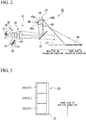
- FIG. 2 is a schematic view showing the projection module 10 of the embodiment.
- the projection module 10 of the embodiment includes a light source unit 20, a diffusion plate 24, an incident optical system 25, an image generating unit 31 and a projecting optical system (a projecting unit) 41.
- the light source unit 20 is an array light source in which a plurality of light sources 21 are arranged to configure an array light emitting surface. That is, the light source unit 20 has the plurality of light sources 21.
- the light sources 21 emit visible light.
- a light emitting diode (LED) light source or a laser light source may be employed as the light source 21.
- the plurality of light sources 21 are individually turned on and off by a light emitting volume control part52, and thus a light emitting volume is controlled. That is, the light emitting volume of the light sources 21 can be adjusted from 100% at which the light emitting volume is maximized to 0%, which is a state in which the light sources 21 are completely turned off.
- the light sources 21 are in an off state when the light emitting volume is 0%.
- FIG. 3 is a schematic view of the light source unit 20 of the embodiment.
- the light source unit 20 of the embodiment has the three light sources 21 and a package section 22 for a light source.
- the three light sources 21 are arranged in an upward/downward direction (a vertical direction) of the vehicle.
- the three light sources 21 are contained in the package section 22 for a light source. A slight gap is formed between the neighboring light sources 21.
- the number of the light sources 21 is not limited as long as the light source unit 20 has the plurality of light sources 21.
- the plurality of light sources 21 of the light source unit 20 are arranged in the upward/downward direction in the embodiment, the light sources 21 may be arranged in a direction perpendicular to a widthwise direction of the vehicle. As the light sources 21 are arranged in this way, light distribution regions formed on a road surface by light emitted from the light sources 21 can be formed to be arranged in the forward/rearward direction of the vehicle.
- an array light source in which the plurality of light sources are arranged in vertical and horizontal directions may be employed as a variant of the light source unit.
- the light radiated from the light sources arranged in one direction is arranged in the forward/rearward direction of the vehicle on the projected road surface.
- the light source disposed at the uppermost side is a first light source 21A
- the light source disposed at the lowermost side is a third light source 21C
- the light source disposed between the first light source 21A and the third light source 21C is a second light source 21B.
- the first light source 21A forms a light distribution region (a first light distribution region 50A) at a position on the road surface 57 farthest from a vehicle 55.
- the third light source 21C forms a light distribution region (a third light distribution region 50C) at a position on the road surface 57 nearest to the vehicle 55.
- the second light source 21B forms a light distribution region (a second light distribution region 50B) between those of the first light source 21A and the third light source 21C on the road surface 57. That is, the plurality of light sources 21 arranged in an arrangement direction perpendicular to the widthwise direction of the vehicle form a plurality of light distribution regions that are aligned on the road surface from a near side of the vehicle toward a far side of the vehicle, respectively.
- the diffusion plate 24 is disposed between the light source unit 20 and the incident optical system 25.
- the diffusion plate 24 allows diffusion and transmission of the entering light.
- the light emitted from the light source unit 20 and passing through the diffusion plate 24 enters the incident optical system 25 in a state in which a light diameter is enlarged.
- a fluorescent body plate configured to receive light radiated from the light sources 21 and radiate white light having diffusibility may be used as the diffusion plate 24.
- the light sources 21 radiate blue light (that may include ultraviolet light)
- the blue light that enters the fluorescent body plate (the diffusion plate 24) including fluorescent body particles therein passes through the fluorescent body plate while being diffused therein, and a wavelength of some of the blue light is converted by the fluorescent body particles.
- the blue light emitted from the light sources 21 and the yellow light discharged by excitation of the fluorescent body particles are mixed, and as a result, the white light having diffusibility is radiated from the fluorescent body plate.
- a dispersing agent that diffuses blue light in the fluorescent body plate may be added to the fluorescent body plate.
- the light source unit 20 As described above, in the light source unit 20, a slight gap is formed between the neighboring light sources 21 (see FIG. 3 ). When the light radiated from the light sources 21 is projected to the road surface, the gap between the light sources 21 may cause formation of a dark section in the image 58 on the road surface 57. According to the embodiment, as the diffusion plate 24 is disposed between the light source unit 20 and the incident optical system 25, the light radiated from the light source unit 20 can be blurred and enter the incident optical system 25, and formation of the dark section in the image 58 on the road surface 57 can be minimized.
- the incident optical system 25 condenses light from the light sources 21 and irradiates the reflection control surface of the image generating unit 31 with the light.
- the incident optical system 25 is constituted by one or a plurality of lenses, or the like.
- the image generating unit 31 modulates the light emitted from the light sources 21 and generates an image.
- the image generating unit 31 is constituted by a reflection type digital light deflection apparatus (a digital mirror device (DMD)).
- the image generating unit 31 constituted by the reflection type digital light deflection apparatus has a reflection control surface configured by arranging a plurality of tiltable mirror elements.
- each tilting angle is controlled toward a reflection side or a light shielding side according to a signal from the control unit 13.
- the image generating unit 31 generates a reflection pattern (an image) 39 having an arbitrary shape using the reflected light of the plurality of mirror elements that are tilted toward the reflection side.
- the image generating unit 31 generates a reflection pattern 39 of an arrow shape.
- a light shielding member 32 configured to shield light from the mirror elements that are tilted toward the light shielding side is installed on the projection module 10.
- the projecting optical system 41 radiates the reflection pattern 39 generated in the image generating unit 31 to the front of the vehicle as the image 58 and projects the reflection pattern 39 on the road surface 57.
- the projecting optical system 41 includes a light condensing optical system 42, a return mirror 43 and a reflecting apparatus 44.
- the projecting optical system 41 radiates the image 58 in the plurality of light distribution regions.
- the light condensing optical system 42 is constituted by one or a plurality of lenses, or the like.
- the light condensing optical system 42 radiates the reflection pattern 39 generated by the image generating unit 31 to a reflecting section 45 of the reflecting apparatus 44 via the return mirror 43.
- the light condensing optical system 42 condenses the reflection pattern 39 emitted from the image generating unit 31 and images an intermediate image 59.
- the return mirror 43 is a mirror configured to reflect the light from the light condensing optical system 42 toward the reflecting section 45.
- the reflecting apparatus 44 has the reflecting section 45.
- the reflecting section 45 reflects the light condensed by the light condensing optical system 42 toward the road surface 57.
- the reflecting section 45 is a concave surface reflector for enlargement projection.
- the reflecting section 45 has a reflecting surface 45a. That is, the projecting optical system 41 has the reflecting surface 45a.
- the reflecting section 45 reflects the light condensed by the light condensing optical system 42 in the reflecting surface 45a and projects the reflected light to a predetermined region of the road surface 57.
- the reflecting surface 45a is a concave surface shape constituted by a non-spherical free curved surface.
- the reflecting surface 45a is disposed downstream from the intermediate image 59 formed by the light condensing optical system 42. Accordingly, the light is imaged upstream from the reflecting surface 45a, enters the reflecting surface 45a having a concave surface shape while spreading in the diffusion direction, and is condensed again by being reflected by the reflecting surface 45a.
- upstream and downstream refer to a sequential relation along a transmittance path of light (i.e., an upstream side and a downstream side in an optical path), and do not refer to disposition of areas in the projection module 10.
- a region 45b in front of the reflecting surface 45a in a projecting direction reflects light toward the road surface 57 on the side near the vehicle.
- a region 45c in rear of the reflecting surface 45a in the projecting direction reflects light toward the road surface 57 on the side far from the vehicle.
- the reflecting surface 45a is formed by continuously varying a curvature according to a distance from a projecting target (from the side near the vehicle to the side far from the vehicle on the road surface 57) from the region 45c on the rear side in the projecting direction toward the region 45b on the front side in the projecting direction. That is, the reflecting surface 45a has a curvature that is gradually increased from the rear side in the projecting direction toward the front side in the projecting direction.
- the light is reflected by the region 45b on the front side in the projecting direction in which the light is reflected toward the side near the vehicle, a distance between a region in which light is reflected by the reflecting surface 45a and a region in which an image is formed on the road surface 57 that is an image plane of the road surface 57 can be reduced, and out of focus of the imaged image 58 can be minimized.
- the reflecting section 45 configured to reflect the light including the image 58 toward the road surface 57 is formed by continuously varying a curvature according to a distance from a projecting target (from the side near the vehicle to the side far from the vehicle on the road surface). Accordingly, the image can be clearly displayed on the road surface 57, and the image 58 having high quality in which areas that are out of focus do not occur can be formed.
- the road surface drawing system 1 including the projection module 10 is mounted on the vehicle 55, and radiates light from the vehicle 55 toward the road surface 57.
- the road surface drawing system 1 performs a predetermined drawing that emphasizes a traveling path of the vehicle 55 on the road surface 57 in front of the vehicle 55.
- the road surface drawing system 1 draws a pair of rod-shaped lanes extending in the traveling direction of the vehicle 55 as the predetermined image 58 that emphasizes the traveling path.
- the pair of rod-shaped lanes are disposed to be slightly wider than a vehicle width of the vehicle 55.
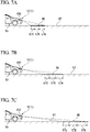
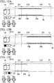
- FIG. 4A to FIG. 4C are views showing examples of the image 58 drawn on the road surface 57 when light is emitted from only the third light source 21C, the second light source 21B and the first light source 21A, respectively.
- a first road surface region 57A, a second road surface region 57B and a third road surface region 57C that are sequentially arranged from a region far from the vehicle 55 toward a region near the vehicle 55 are set on the road surface 57 in front of the vehicle 55.
- the first to third light sources 21A to 21C form the first to third light distribution regions 50A to 50C in the first to third road surface regions 57A to 57C on the road surface 57.
- the road surface drawing system 1 draws the image 58 on the first to third road surface regions 57A to 57C at display positions of the image 58 by controlling light emitting volumes of the first to third light sources 21A to 21C.
- FIG. 4A is a view showing the image 58 when the third light source 21C is lit up and the first light source 21A and the second light source 21B are turned off.
- FIG. 4A is a view showing an example of the image 58 drawn on the road surface 57 when a light emitting volume of the third light source 21C is set to 60% and light emitting volumes of the second light source 21B and the first light source 21A are set to 0%.
- the light radiated from the first light source 21A forms a reflected image as the light is reflected in the image generating unit 31, and further forms the image 58 in the first light distribution region 50A on the road surface 57.
- the image 58 is preferably displayed on the third road surface region 57C only as shown in FIG. 4A .
- a relatively low speed for example 30 km/hour
- the image 58 is preferably displayed on the third road surface region 57C only as shown in FIG. 4A .
- the image 58 could interfere with operation by a driver of another vehicle since a vehicle-to-vehicle distance with respect to other vehicles that travel in front of the vehicle 55 is small when the vehicle 55 travels at a low speed.
- the other light sources (the first and second light sources 21A and 21B) that handle the other regions (the first and second road surface regions 57A and 57B) can be turned off, and the road surface drawing system 1 having high energy efficiency can be realized.
- FIG. 4B is a view showing the image 58 when the second light source 21B is lit up and the first light source 21A and the third light source 21C are turned off.
- FIG. 4B is a view showing an example of the image 58 drawn on the road surface 57 when a light emitting volume of the second light source 21B is set to 80% and light emitting volumes of the first light source 21A and the third light source 21C are set to 0%.
- the light radiated from the second light source 21B forms a reflected image as the light is reflected in the image generating unit 31, and further forms the image 58 in the second light distribution region 50B on the road surface 57.
- the image 58 is preferably displayed only on a region spaced a certain distance from the vehicle 55 of the road surface 57 (i.e., the second road surface region 57B).
- the first and third light sources 21A and 21C can be turned off, and the road surface drawing system 1 having high energy efficiency can be realized.
- FIG. 4C is a view showing the image 58 when the first light source 21A is lit up and the second light source 21B and the third light source 21C are turned off.
- FIG. 4C is a view showing an example of the image 58 drawn on the road surface 57 when a light emitting volume of the first light source 21A is set to 100% and light emitting volumes of the second light source 21B and the third light source 21C are set to 0%.
- the light radiated from the third light source 21C forms a reflected image as the light is reflected in the image generating unit 31, and further the image 58 is formed in the third light distribution region 50C on the road surface 57.
- the image 58 is preferably displayed only on the region of the road surface 57 farthest from the vehicle 55 (i.e., the first road surface region 57A). This is because necessity to display an image on the near region is low since a driver's attention is directed to a far side of the vehicle 55 when the vehicle 55 travels at a high speed.
- the second and third light sources 21B and 21C can be turned off, and the road surface drawing system 1 having high energy efficiency can be realized.
- a display length of the image 58 is preferably increased in the traveling direction of the vehicle 55 while varying a display position of the image 58 as a speed of the vehicle 55 is increased. Further, the display length of the image 58 in the traveling direction of the vehicle 55 can be easily varied by adjusting a shape of a reflected image formed in the image generating unit 31. Accordingly, a range of the image 58 that is visually recognized by a driver in the vehicle 55 can be sufficiently widened as the speed of the vehicle 55 is increased.
- a display length of the image 58 in the traveling direction of the vehicle 55 is schematically displayed and different from an actual length.
- the road surface drawing system 1 since the light is radiated diagonally from a certain height of the vehicle 55 toward the road surface, a luminous density of the light entering the road surface is decreased as a distance from the vehicle 55 is increased. Accordingly, when uniform light is radiated from the road surface drawing system 1 to the road surface 57, an illuminance of the image 58 on the road surface 57 is decreased when displayed at a position separated from the vehicle 55.
- light emitting volumes of the first to third light sources 21A to 21C are individually controlled by the light emitting volume control part 52.
- a light emitting volume of the third light source 21C is set to 60% when the third road surface region 57C is irradiated with light
- a light emitting volume of the second light source 21B is set to 80% when the second road surface region 57B is irradiated with light
- a light emitting volume of the first light source 21A is set to 100% when the first road surface region 57A is irradiated with light. That is, the light emitting volumes of the light sources (the first to third light sources 21A to 21C) can be adjusted according to distances of the formed light distribution regions (the first to third light distribution regions 50A to 50C) from the vehicle 55.
- the road surface drawing system 1 having high energy efficiency can be realized.
- the image generating unit 31 can drive ON and OFF of reflection by inclinations of mirror elements and adjust a duty ratio of ON and OFF.
- the duty ratio of the image generating unit 31 may be adjusted and an illuminance in a single light distribution region may be adjusted according to the distance from the vehicle 55. In this case, as the region gets closer to the vehicle 55, a time in which the adjusted duty ratio is turned OFF is increased.
- FIG. 5A is a view showing the image 58 when the image 58 is displayed throughout the first to third road surface regions 57A to 57C.
- the first to third light sources 21A to 21C emit light.
- the light radiated from the first to third light sources 21A to 21C forms the image 58 in the first to third light distribution regions 50A to 50C on the road surface 57.
- a light emitting volume of the first light source 21A corresponding to the first light distribution region 50A is 90%
- a light emitting volume of the second light source 21B corresponding to the second light distribution region 50B is 80%
- a light emitting volume of the third light source 21C corresponding to the third light distribution region 50C is 60%.
- each of the light emitting volumes of the light sources are adjusted with reference to a light emitting volume at which a light emitting volume of the light source is sufficiently obtained even at a farthest portion from the vehicle among the respective corresponding road surface regions.
- FIG. 5B is a view showing the image 58 when the image 58 is displayed throughout the first and second road surface regions 57A and 57B.
- the first and second light sources 21A and 21B emit light.
- the light radiated from the first and second light sources 21A and 21B forms the image 58 in the first and second light distribution regions 50A and 50B on the road surface 57.
- a light emitting volume of the first light source 21A corresponding to the first light distribution region 50A is 100%
- a light emitting volume of the second light source 21B corresponding to the second light distribution region 50B is 80%
- the third light source 21C corresponding to the third light distribution region 50C is turned off.
- FIG. 5C is a view showing the image 58 when the image 58 is displayed throughout the second and third road surface regions 57B and 57C.
- the second and third light sources 21B and 21C emit light.
- the light radiated from the second and third light sources 21B and 21C forms the image 58 in the second and third light distribution regions 50B and 50C on the road surface 57.
- the first light source 21A corresponding to the first light distribution region 50A is turned off
- a light emitting volume of the second light source 21B corresponding to the second light distribution region 50B is 70%
- a light emitting volume of the third light source 21C corresponding to the third light distribution region 50C is 60%.
- the light emitting volumes of the light sources are adjusted according to the distance of the formed light distribution regions (the first to third light distribution regions 50A to 50C) from the vehicle 55, uniformity of the illuminance on the road surface in the image 58 extending throughout a plurality of road surface regions can be increased.
- Brightness in the vicinity of a boundary between the light distribution regions on the sides having a high light emitting volume (i.e., far sides) in the image 58 that bridges a pair of neighboring light distribution regions may be adjusted by adjusting a duty ratio of the image generating unit 31 in the embodiment. In this case, a difference of the illuminance on the road surface 57 may be reduced and drawing of the natural image 58 may be realized in the vicinity of the boundary between the pair of light distribution regions.
- the imaging apparatus 15 functions as a traveling path recognition unit configured to recognize a traveling path in front of the vehicle by imaging and processing a forward side of the vehicle.
- the vehicle speed detecting unit 16 detects a speed of the vehicle.
- the vehicle speed detecting unit 16 is configured to directly acquire vehicle speed information from the vehicle. Information of a traveling path and a vehicle speed acquired by the imaging apparatus 15 and the vehicle speed detecting unit 16 is transmitted to a control part 51 of the control unit 13 as an electrical signal.
- the control unit 13 has a memory 53 in which control information or the like of various images is previously set, the control part 51 configured to generate a control signal on the basis of electrical signals from the memory 53, the imaging apparatus 15 and the vehicle speed detecting unit 16, a driving unit 54 configured to drive the image generating unit 31 on the basis of the control signal, and the light emitting volume control part 52 configured to individually change light emitting volumes of the plurality of light sources 21.
- the control unit 13 generates an image by performing processing of controlling tilting states of the mirror elements of the image generating unit 31.
- control unit 13 determines a position at which the image 58 is displayed on the road surface 57 based on information of a speed of the vehicle 55 acquired by the vehicle speed detecting unit 16, and adjusts the light emitting volumes of the plurality of light sources 21 using the light emitting volume control part 52.
- the control unit 13 changes a distance of the image 58 with respect to the vehicle 55 on the basis of the detection result of the vehicle speed detecting unit 16. Accordingly, the road surface drawing system 1 displays the image 58 on the road surface 57 far from the vehicle 55 when the speed of the vehicle 55 is high, and displays the image 58 on the road surface 57 near the vehicle 55 when the speed of the vehicle 55 is low.
- an effect of a warning notice by the image can be increased by displaying the image on a place that can be easily recognized by a driver.
- the plurality of light sources 21 form a plurality of light distribution regions (the first to third light distribution regions 50A to 50C) that are arranged on the road surface 57 from the side near the vehicle 55 toward the side far from the vehicle 55, respectively, and the control unit 13 switches a light emitting state of at least one of the light sources 21 on the basis of the detection result of the vehicle speed detecting unit 16. Accordingly, since a distance of the image 58 on the road surface 57 with respect to the vehicle 55 is varied, the image 58 can be displayed on a place that can be easily recognized by a driver without decreasing efficiency of utilization of light radiated from the light sources 21.
- switching a light emitting state of at least one light source means that at least one of the plurality of light sources 21 is switched from ON to OFF or from OFF to ON. In this way, as the at least one light source 21 is switched from ON to OFF or from OFF to ON, a position of a center of the image 58 on the road surface 57 can be moved in the traveling direction of the vehicle 55.
- the plurality of light sources 21 corresponding to the plurality of light distribution regions (the first to third light distribution regions 50A to 50C) arranged from the side near the vehicle 55 toward the side far from the vehicle 55 are installed in the road surface drawing system 1.
- the light emitting volumes of the plurality of light sources 21 are controlled by the light emitting volume control part 52. Accordingly, the illuminance on the road surface 57 can be adjusted at each of the plurality of light distribution regions formed on the road surface 57, and the illuminance on the road surface 57 of the side near the vehicle 55 and the side far from the vehicle 55 can be substantially uniform.
- the light emitting volume control part 52 preferably performs control of causing the light emitting volume of the light source 21 that forms a light distribution region at the far side of the vehicle 55 among the plurality of light sources 21 to be larger than the light emitting volume of the light source 21 that forms a light distribution region at the near side of the vehicle 55. Accordingly, the light emitting volume of the light source 21 that illuminates the light distribution region located at the far side of the vehicle 55, among the plurality of light distribution regions formed on the road surface 57, can be increased, and the illuminance in the image 58 can be substantially uniform.
- the reflecting surface 45a of the projecting optical system 41 has a configuration in which a curvature is gradually increased from a rear side in the projecting direction toward a front side in the projecting direction. Accordingly, as described above, it is possible to provide a lighting tool for a vehicle capable of minimizing out of focus of an image and clearly displaying an image on a road surface.
- the imaging apparatus 15 functions as a traveling path recognition unit configured to detect road conditions in front of the vehicle 55.
- the control unit 13 reflects a result recognized by the imaging apparatus 15 to the image 58.
- the road surface drawing system 1 performs drawing that emphasizes a traveling path on the road surface 57 by the projection module 10 on the basis of the recognized result acquired by the imaging apparatus 15. Accordingly, the road surface drawing system 1 can increase safety by assisting a driver's operation.
- the control unit 13 may play the role of assisting a driver's visual recognition by curving a pair of rod-shaped lanes as the image 58 and flickering the image 58 according to a variation of the traveling path acquired by the imaging apparatus 15.
- the control unit 13 may determine whether the vehicle 55 is able to travel on the basis of the recognized result and reflect the determination result to the image 58 when an obstacle that impedes traveling of the vehicle 55 on the traveling path is recognized by the imaging apparatus 15.
- the road conditions acquired from the imaging apparatus 15 include a traffic lane, a curbstone, a state of a rut, or the like, on the road surface.
- the traveling path information acquisition unit 17 acquires the road conditions in front of the vehicle 55 from the outside.
- the control unit 13 reflects the information acquired by the traveling path information acquisition unit 17 to the image 58.
- the road conditions acquired from the outside can be clearly acknowledged to a driver.
- the road conditions acquired from the outside include information or the like acquired from a global positioning system (GPS) and a vehicle information and communication system (VICS, registered trademark).
- GPS global positioning system
- VICS vehicle information and communication system
- the method is a method of drawing an image that emphasizes a traveling path of a vehicle on a road surface in front of the vehicle, and the method includes: drawing the traveling path by drawing the image on the road surface by radiating light onto the road surface; and detecting a speed of the vehicle; wherein the drawing of the traveling path includes a step of modulating the radiated light and forming the image, and a step of projecting a light including the image to the road surface, and changing a distance between the image and the vehicle on the basis of a detection result of the detected vehicle speed.
- a reflecting apparatus 144 of a variant that can be employed instead of the above-mentioned reflecting apparatus 44 will be described with reference to FIG. 6 . Further, the same components as those of the above-mentioned embodiment are designated by the same reference numerals and description thereof will be omitted.
- the reflecting apparatus 144 of the variant has a plurality of (in the embodiment, three) reflecting sections 145, and a switching unit 146.
- the reflecting sections 145 reflect the light condensed by the light condensing optical system 42 toward the road surface 57.
- the switching unit 146 has a shaft section 146a, and a driving unit 146b configured to rotate and drive the shaft section 146a about a shaft thereof.
- the plurality of reflecting sections 145 are fixed to the shaft section 146a at equal intervals in the circumferential direction with respect to an axial center of the shaft section 146a.
- the switching unit 146 is disposed to switch one of the plurality of reflecting sections 145 to a light receiving position at which light radiated from the light condensing optical system 42 is received according to rotation of the shaft section 146a by the driving unit 146b.
- the reflecting apparatus 144 has a reflecting section 145X for a short range, a reflecting section 145Y for an intermediate range, and a reflecting section 145Z for a long range.
- Reflecting surfaces 145a of the reflecting sections 145X, 145Y and 145Z are set to reflect light toward the regions on the road surface 57 having different distances.
- the reflecting surfaces 145a of the reflecting section 145X for a short range, the reflecting section 145Y for an intermediate range and the reflecting section 145Z for a long range are formed to have curved surfaces having a larger average curvature as a reflected light is radiated closer.
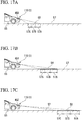
- a state in which the image 58 is displayed on the road surface 57 using the reflecting section 145X for a short range is shown in FIG.
- FIG. 7A a state in which the image 58 is displayed on the road surface 57 using the reflecting section 145Y for an intermediate range is shown in FIG. 7B , and a state in which the image 58 is displayed on the road surface 57 using the reflecting section 145Z for a long range is shown in FIG. 7C .
- regions on the road surface 57 that can be radiated by the reflecting sections 145X, 145Y and 145Z are different from each other.
- regions on the road surface 57 that can be radiated by the reflecting sections 145X, 145Y and 145Z are partitioned into the first to third road surface regions 57A to 57C corresponding to the first to third light sources 21A to 21C, respectively.
- the reflecting surfaces 145a of the plurality of reflecting sections 145 that reflect light toward the regions having different distances are switched by the switching unit 146, images can be clearly displayed at different distances on the road by the reflecting surfaces 145a. Accordingly, since the distance of the image 58 on the road surface 57 with respect to the vehicle 55 is varied, the image 58 can be displaced on a place that can be easily visually recognized by a driver without decreasing efficiency of utilization of light radiated from the light sources 21.
- the road surface drawing system 1 configured to clearly display images at the distances can be provided.
- the reflected light is radiated to the long range, diffusion of light and a decrease in illuminance can be prevented.
- the variant can exhibit the same effect as the above-mentioned embodiment. That is, outputs of the light sources corresponding to the plurality of road surface regions (the first to third road surface regions 57A to 57C) partitioned on the road surface 57 can be adjusted, and the illuminance of the road surface 57 on the side near the vehicle 55 and the side far from the vehicle 55 can be substantially uniform.
- a duty ratio of the image generating unit 31 can be adjusted, and the illuminance in the light distribution region can be adjusted according to the distance from the vehicle 55.
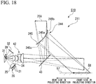
- FIG. 8 is a schematic view showing a projection module (a traveling path drawing unit) 210 of Variant 2. Further, the components of the same aspect as the above-mentioned embodiment are designated by the same reference numerals and description thereof will be omitted.
- the projection module 210 of the variant includes a reflecting apparatus 244 having a reflecting section 245.
- the reflecting section 245 has a reflecting surface 245a formed in a convex surface shape.
- the reflecting surface 245a is disposed upstream from an intermediate image 259 formed by the light condensing optical system 42. Accordingly, light enters the reflecting surface 245a having the convex surface shape while being condensed, and enters the front side by adjusting a distance between a reflecting surface and an image plane using the reflecting surface 245a.
- the reflecting surface 245a having the convex surface shape has a curvature that is gradually increased from the rear side in the projecting direction toward the front side in the projecting direction.
- a region 245b in front of the reflecting surface 245a in the projecting direction reflects light toward the road surface 57 on the side far from the vehicle.
- a region 245c at rear of the reflecting surface 245a in the projecting direction reflects light toward the road surface 57 on the side near the vehicle.
- the reflecting surface 245a is formed by continuously varying a curvature according to a distance from a projecting target (from the side near the vehicle to the side far from the vehicle on the road surface 57).
- the reflecting surface 245a has a curvature that is gradually increased from the rear side in the projecting direction toward the front side in the projecting direction. Accordingly, in comparison with the region 245b on the front side in the projecting direction in which light is reflected toward the side far from the vehicle, the light can be reflected by the region 245c on the rear side in the projecting direction in which light is reflected toward the side near the vehicle, a distance between the region in which light is reflected by the reflecting surface 245a and the region in which an image is imaged on the road surface 57, which is an image plane, can be reduced, and out of focus of the imaged image 58 can be minimized.
- FIG. 9 is a schematic view showing a part of a road surface drawing system 301 of Variant 3. Further, the components of the same aspect as the above-mentioned embodiment are designated by the same reference numerals and description thereof will be omitted.
- the road surface drawing system 301 includes a projection module (a traveling path drawing unit) 310, the vehicle speed detecting unit 16, an imaging apparatus (a traveling path recognition unit) 15 and the control unit 13.
- the projection module 310 of the variant has three light source units 320, an incident optical system 325 and the image generating unit 31 which are shown in FIG. 9 , and the projecting optical system 41 not shown in FIG. 9 (omitted in FIG. 9 ).
- the three light source units 320 are classified into a red light source unit 320R, a green light source unit 320G and a blue light source unit 320B.
- the red light source unit 320R has three red light sources 321R.
- the green light source unit 320G has three green light sources 321G.
- the blue light source unit 320B has three blue light sources 321B.
- Three light sources of the red light source unit 320R, the green light source unit 320G and the blue light source unit 320B are arranged in the upward/downward direction.
- the three light sources of the red light source unit 320R, the green light source unit 320G and the blue light source unit 320B form a plurality of light distribution regions arranged from the side near the vehicle to the side far from the vehicle on the road surface. That is, the three light sources of the red light source unit 320R, the green light source unit 320G and the blue light source unit 320B function as the first to third light sources 21A to 21C of the above-mentioned embodiment.
- the red light source unit 320R, the green light source unit 320G and the blue light source unit 320B are connected to the light emitting volume control part 52.
- the light emitting volumes of the light sources of the red light source unit 320R, the green light source unit 320G and the blue light source unit 320B are controlled by the light emitting volume control part 52.
- the incident optical system 325 has a photosynthetic apparatus 326 and three lens bodies 327.
- the photosynthetic apparatus 326 is a rectangular parallelepiped cross dichroic prism that is known in the related art.
- the photosynthetic apparatus 326 has three incidence surfaces 326a, one light emitting surface 326b and a pair of reflecting surfaces 326c. A wavelength selective reflection film is formed on the pair of reflecting surfaces 326c.
- the three incidence surfaces 326a face the red light source unit 320R, the green light source unit 320G and the blue light source unit 320B via the lens bodies 327, respectively.
- the photosynthetic apparatus 326 synthesizes red light, green light and blue light that enter from the incidence surfaces 326a and emit the synthesized light from the light emitting surface 326b as white light.
- the light emitted from the photosynthetic apparatus 326 enters the image generating unit 31.
- FIG. 10 is a schematic view showing an example of a light distribution pattern P and the predetermined image 58 formed by the road surface drawing system 301 of the variant.
- the road surface drawing system 301 forms the light distribution pattern P as a headlight for a vehicle while displaying the image 58 that emphasizes a traveling path on the road surface 57.
- the image generating unit 31 and the plurality of light source units 320 are connected to the control unit 13.
- the image generating unit 31 is controlled by the control part 51 via the driving unit 54 in the control unit 13.
- the light sources of the light source units 320 are controlled by the control part 51 via the light emitting volume control part 52 in the control unit 13.
- the image generating unit 31 switches a light distribution pattern generated state in which the light distribution pattern P as the headlight for a vehicle is generated and a traveling path emphasized state in which the image 58 that emphasizes the traveling path is generated, at a high speed through control by the control part 51. That is, the image generating unit 31 generates the light distribution pattern P at one moment and generates the image 58 at another moment by switching inclination states of the plurality of mirror elements at a high speed.
- the three light source units 320 emit light and cause the light to enter the image generating unit 31 at a moment when the image generating unit 31 becomes the light distribution pattern generated state. In addition, one or two of the three light source units 320 emit light and the other light source unit 320 is turned off at a moment when the image generating unit 31 becomes the traveling path emphasized state.
- the light radiated from the plurality of light source units 320 passes through the photosynthetic apparatus 326 and enters the image generating unit 31.
- the three light source units 320 emit light, the light radiated from the lights source units 320 are synthesized in the photosynthetic apparatus 326 to become white. Accordingly, here, white light enters the image generating unit 31.
- the road surface drawing system 301 displays the image 58 having a different color from the white light on the road surface 57 while forming the light distribution pattern P having white color on the road surface 57. Since the light distribution pattern generated state and the traveling path emphasized state are switched at a high speed, it is observed by a user that the light distribution pattern P and the image 58 on the road surface 57 are simultaneously displayed.
- the red light source unit 320R radiates red light regardless of a state of the image generating unit 31.
- the green light source unit 320G and the blue light source unit 320B radiate green light and blue light at a moment when the image generating unit 31 becomes the light distribution pattern generated state, respectively, and are turned off at a moment when the image generating unit 31 becomes the traveling path emphasized state. Accordingly, the image 58 can be displayed in red on the road surface 57.
- a color scheme of the image 58 may be switched on the road surface 57.
- the image 58 that prompts a warning notice of the traveling path to a driver can be displayed with visible light having a different color from the white light while forming the light distribution pattern P as the headlight for a vehicle using the white light.
- the projection module 310 is also used as the headlight for a vehicle, the entire apparatus can be reduced in size in comparison with the case in which a drawing apparatus for displaying an image that emphasizes a traveling path and the headlight for a vehicle are individually installed.
- the road surface drawing system 301 since the road surface drawing system 301 has the red light source unit 320R, the green light source unit 320G and the blue light source unit 320B, the color scheme of the image 58 can be changed over time on the road surface 57. Accordingly, the image can be emphasized on the road surface 57, and an effect of prompting a warning notice to a driver can be enhanced.
- the image generating unit may be a drawing apparatus or the like obtained by combining a transmissive spatial modulator such as a liquid crystal or the like, a scanning mirror and a fluorescent body.
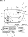
- FIG. 11 is a schematic view of a lighting tool 110 for a vehicle according to the second embodiment.
- the lighting tool 110 for a vehicle of the embodiment is an apparatus for diagonally radiating light including an image from the vehicle toward a road surface.
- the lighting tool 110 for a vehicle includes a projection module 11 that radiates a forward side of the vehicle with light and the control unit 13 configured to control the projection module 11.
- an imaging apparatus (a traveling path recognition unit) 15 configured to detect a situation in the front and transmit the detected situation to the control unit 13 and the vehicle speed detecting unit 16 configured to detect a speed of the vehicle are connected to configure the road surface drawing system 1. That is, the road surface drawing system 1 according to the embodiment has the lighting tool 110 for a vehicle, the imaging apparatus 15 and the vehicle speed detecting unit 16. First, the road surface drawing system 1 detects a speed of the vehicle using the vehicle speed detecting unit 16 while imaging an image in front of the vehicle using the imaging apparatus 15 installed in the front of the vehicle (for example, on the side of a front glass of a rearview mirror).
- control unit 13 analyzes image information acquired by the imaging apparatus 15 and controls the projection module 11 based on the information of the speed of the vehicle acquired by the vehicle speed detecting unit 16. Accordingly, a drawing (an image) 58 is displayed on the road surface 57 in front of the vehicle.
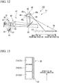
- FIG. 12 is a schematic view showing the projection module 11 of the embodiment.
- the projection module 11 of the embodiment includes the light source unit 20, the diffusion plate 24, the incident optical system 25, the image generating unit 31 and a projecting optical system (a projecting unit) 41.
- the light source unit 20 is an array light source in which a plurality of light sources 21 are arranged to configure an array light emitting surface. That is, the light source unit 20 has the plurality of light sources 21.
- the light sources 21 emit visible light.
- a light emitting diode (LED) light source or a laser light source may be employed as the light source 21.
- the plurality of light sources 21 are individually turned on and off by a light emitting volume control part52, and thus a light emitting volume is controlled. That is, the light emitting volume of the light sources 21 can be adjusted from 100% at which the light emitting volume is maximized to 0%, which is a state in which the light sources 21 are completely turned off.
- the light sources 21 are in an off state when the light emitting volume is 0%.
- FIG. 13 is a schematic view of the light source unit 20 of the embodiment.
- the light source unit 20 of the embodiment has the three light sources 21 and a package section 22 for a light source.
- the three light sources 21 are arranged in an upward/downward direction (a vertical direction) of the vehicle.
- the three light sources 21 are contained in the package section 22 for a light source. A slight gap is formed between the neighboring light sources 21.
- the number of the light sources 21 is not limited as long as the light source unit 20 has the plurality of light sources 21.
- the plurality of light sources 21 of the light source unit 20 are arranged in the upward/downward direction in the embodiment, the light sources 21 may be arranged in a direction perpendicular to a widthwise direction of the vehicle. As the light sources 21 are arranged in this way, light distribution regions formed on a road surface by light emitted from the light sources 21 can be formed to be arranged in the forward/rearward direction of the vehicle.
- an array light source in which the plurality of light sources are arranged in vertical and horizontal directions may be employed as a variant of the light source unit.
- the light radiated from the light sources arranged in one direction is arranged in the forward/rearward direction of the vehicle on the projected road surface.
- the light source disposed at the uppermost side is a first light source 21A
- the light source disposed at the lowermost side is a third light source 21C
- the light source disposed between the first light source 21A and the third light source 21C is a second light source 21B.
- the first light source 21A forms a light distribution region (a first light distribution region 50A) at a position on the road surface 57 farthest from a vehicle 55.
- the third light source 21C forms a light distribution region (a third light distribution region 50C) at a position on the road surface 57 nearest to the vehicle 55.
- the second light source 21B forms a light distribution region (a second light distribution region 50B) between those of the first light source 21A and the third light source 21C on the road surface 57. That is, the plurality of light sources 21 arranged in an arrangement direction perpendicular to the widthwise direction of the vehicle form a plurality of light distribution regions that are aligned on the road surface from a near side of the vehicle toward a far side of the vehicle, respectively.
- the diffusion plate 24 is disposed between the light source unit 20 and the incident optical system 25.
- the diffusion plate 24 allows diffusion and transmission of the entering light.
- the light emitted from the light source unit 20 and passing through the diffusion plate 24 enters the incident optical system 25 in a state in which a light diameter is enlarged.
- a fluorescent body plate configured to receive light radiated from the light sources 21 and radiate white light having diffusibility may be used as the diffusion plate 24.
- the light sources 21 radiate blue light (that may include ultraviolet light)
- the blue light that enters the fluorescent body plate (the diffusion plate 24) including fluorescent body particles therein passes through the fluorescent body plate while being diffused therein, and a wavelength of some of the blue light is converted by the fluorescent body particles.
- the blue light emitted from the light sources 21 and the yellow light discharged by excitation of the fluorescent body particles are mixed, and as a result, the white light having diffusibility is radiated from the fluorescent body plate.
- a dispersing agent that diffuses blue light in the fluorescent body plate may be added to the fluorescent body plate.
- the light source unit 20 As described above, in the light source unit 20, a slight gap is formed between the neighboring light sources 21 (see FIG. 13 ). When the light radiated from the light sources 21 is projected to the road surface, the gap between the light sources 21 may cause formation of a dark section in the drawing 58 on the road surface 57. According to the embodiment, as the diffusion plate 24 is disposed between the light source unit 20 and the incident optical system 25, the light radiated from the light source unit 20 can be blurred and enter the incident optical system 25, and formation of the dark section in the drawing 58 on the road surface 57 can be minimized.
- the incident optical system 25 condenses light from the light sources 21 and irradiates the reflection control surface of the image generating unit 31 with the light.
- the incident optical system 25 is constituted by one or a plurality of lenses, or the like.
- the image generating unit 31 modulates the light emitted from the light sources 21 and generates an image.
- the image generating unit 31 is constituted by a reflection type digital light deflection apparatus (a digital mirror device (DMD)).
- the image generating unit 31 constituted by the reflection type digital light deflection apparatus has a reflection control surface configured by arranging a plurality of tiltable mirror elements.
- each tilting angle is controlled toward a reflection side or a light shielding side according to a signal from the control unit 13.
- the image generating unit 31 generates a reflection pattern (an image) 39 having an arbitrary shape using the reflected light of the plurality of mirror elements that are tilted toward the reflection side.
- the image generating unit 31 generates a reflection pattern 39 of an arrow shape.
- a light shielding member 32 configured to shield light from the mirror elements that are tilted toward the light shielding side is installed on the lighting tool 110 for a vehicle.
- the projecting optical system 41 radiates the reflection pattern 39 generated in the image generating unit 31 to the front of the vehicle as the drawing 58 and projects the reflection pattern 39 on the road surface 57.
- the projecting optical system 41 includes a light condensing optical system 42, a return mirror 43 and a reflecting apparatus 44.
- the projecting optical system 41 radiates the image 58 in the plurality of light distribution regions.
- the light condensing optical system 42 is constituted by one or a plurality of lenses, or the like.
- the light condensing optical system 42 radiates the reflection pattern 39 generated by the image generating unit 31 to a reflecting section 45 of the reflecting apparatus 44 via the return mirror 43.
- the light condensing optical system 42 condenses the reflection pattern 39 emitted from the image generating unit 31 and images an intermediate image 59.
- the return mirror 43 is a mirror configured to reflect the light from the light condensing optical system 42 toward the reflecting section 45.
- the reflecting apparatus 44 has the reflecting section 45.
- the reflecting section 45 reflects the light condensed by the light condensing optical system 42 toward the road surface 57.
- the reflecting section 45 is a concave surface reflector for enlargement projection.
- the reflecting section 45 has a reflecting surface 45a. That is, the projecting optical system 41 has the reflecting surface 45a.
- the reflecting section 45 reflects the light condensed by the light condensing optical system 42 in the reflecting surface 45a and projects the reflected light to a predetermined region of the road surface 57.
- the reflecting surface 45a is a concave surface shape constituted by a non-spherical free curved surface.
- the reflecting surface 45a is disposed downstream from the intermediate image 59 formed by the light condensing optical system 42. Accordingly, the light is imaged upstream from the reflecting surface 45a, enters the reflecting surface 45a having a concave surface shape while spreading in the diffusion direction, and is condensed again by being reflected by the reflecting surface 45a.
- upstream and downstream refer to a sequential relation along a transmittance path of light (i.e., an upstream side and a downstream side in an optical path), and do not refer to disposition of areas in the lighting tool 110 for a vehicle.
- a region 45b in front of the reflecting surface 45a in a projecting direction reflects light toward the road surface 57 on the side near the vehicle.
- a region 45c in rear of the reflecting surface 45a in the projecting direction reflects light toward the road surface 57 on the side far from the vehicle.
- the reflecting surface 45a is formed by continuously varying a curvature according to a distance from a projecting target (from the side near the vehicle to the side far from the vehicle on the road surface 57) from the region 45c on the rear side in the projecting direction toward the region 45b on the front side in the projecting direction. That is, the reflecting surface 45a has a curvature that is gradually increased from the rear side in the projecting direction toward the front side in the projecting direction.
- the light is reflected by the region 45b on the front side in the projecting direction in which the light is reflected toward the side near the vehicle, a distance between a region in which light is reflected by the reflecting surface 45a and a region in which an image is formed on the road surface 57 that is an image plane of the road surface 57 can be reduced, and out of focus of the imaged drawing 58 can be minimized.
- the reflecting section 45 configured to reflect the light including the image as the drawing 28 toward the road surface 57 is formed by continuously varying a curvature according to a distance from a projecting target (from the side near the vehicle to the side far from the vehicle on the road surface). Accordingly, the image can be clearly displayed on the road surface 57, and the drawing 58 having high quality in which areas that are out of focus do not occur can be formed.
- the road surface drawing system 1 including the lighting tool 110 for a vehicle is mounted on the vehicle 55, and radiates light from the vehicle 55 toward the road surface 57.
- the road surface drawing system 1 performs predetermined drawing that emphasizes a traveling path of the vehicle 55 on the road surface 57 in front of the vehicle 55.
- the road surface drawing system 1 draws a pair of rod-shaped lanes extending in the traveling direction of the vehicle 55 as the predetermined drawing 58 that emphasizes the traveling path.
- the pair of rod-shaped lanes are disposed to be slightly wider than a vehicle width of the vehicle 55.
- the pair of rod-shaped lanes play a role of assisting visual recognition of a driver by curving the lanes or changing a color scheme according to a variation of the traveling path acquired by the imaging apparatus 15.
- FIG. 14A to FIG. 14C are views showing examples of the drawing 58 displayed on the road surface 57 when light is emitted from only the third light source 21C, the second light source 21B and the first light source 21A, respectively.
- a first road surface region 57A, a second road surface region 57B and a third road surface region 57C that are sequentially arranged from a region far from the vehicle 55 toward a region near the vehicle 55 are set on the road surface 57 in front of the vehicle 55.
- the first to third light sources 21A to 21C form the first to third light distribution regions 50A to 50C in the first to third road surface regions 57A to 57C on the road surface 57.
- the road surface drawing system 1 displays the drawing 58 on the first to third road surface regions 57A to 57C at display positions of the drawing 58 by controlling light emitting volumes of the first to third light sources 21A to 21C.
- FIG. 14A is a view showing the drawing 58 when the third light source 21C is lit up and the first light source 21A and the second light source 21B are turned off.
- FIG. 14A is a view showing an example of the drawing 58 drawn on the road surface 57 when a light emitting volume of the third light source 21C is set to 60% and light emitting volumes of the second light source 21B and the first light source 21A are set to 0%.
- the light radiated from the first light source 21A forms a reflected image as the light is reflected in the image generating unit 31, and further forms the drawing 58 in the first light distribution region 50A on the road surface 57.
- the drawing 58 is preferably displayed on the third road surface region 57C only as shown in FIG. 14A . This is because necessity to display the drawing on the distant region is low since a driver's attention is directed to the side near the vehicle 55 when the vehicle 55 travels at a low speed. In addition, this is because the drawing 58 could interfere with operation by a driver of another vehicle since a vehicle-to-vehicle distance with respect to other vehicles that travel in front of the vehicle 55 is small when the vehicle 55 travels at a low speed.
- the drawing 58 when the drawing 58 is displayed only on a region of the road surface 57 in the vicinity of the vehicle 55 (i.e., the third road surface region 57C), the other light sources (the first and second light sources 21A and 21B) that handle the other regions (the first and second road surface regions 57A and 57B) can be turned off, and the road surface drawing system 1 having high energy efficiency can be realized.
- FIG. 14B is a view showing the drawing 58 when the second light source 21B is lit up and the first light source 21A and the third light source 21C are turned off.
- FIG. 14B is a view showing an example of the drawing 58 drawn on the road surface 57 when a light emitting volume of the second light source 21B is set to 80% and light emitting volumes of the first light source 21A and the third light source 21C are set to 0%.
- the light radiated from the second light source 21B forms a reflected image as the light is reflected in the image generating unit 31, and further forms the drawing 58 in the second light distribution region 50B on the road surface 57.
- the drawing 58 is preferably displayed only on a region spaced a certain distance from the vehicle 55 of the road surface 57 (i.e., the second road surface region 57B).
- the first and third light sources 21A and 21C can be turned off, and the road surface drawing system 1 having high energy efficiency can be realized.
- FIG. 14C is a view showing the drawing 58 when the first light source 21A is lit up and the second light source 21B and the third light source 21C are turned off.
- FIG. 14C is a view showing an example of the image 58 drawn on the road surface 57 when a light emitting volume of the first light source 21A is set to 100% and light emitting volumes of the second light source 21B and the third light source 21C are set to 0%.
- the light radiated from the third light source 21C forms a reflected image as the light is reflected in the image generating unit 31, and further the drawing 58 is formed in the third light distribution region 50C on the road surface 57.
- the drawing 58 is preferably displayed only on the region of the road surface 57 farthest from the vehicle 55 (i.e., the first road surface region 57A). This is because necessity to display a drawing on the near region is low since a driver's attention is directed to a far side of the vehicle 55 when the vehicle 55 travels at a high speed.
- the drawing 58 is displayed only on the first road surface region 57A, the second and third light sources 21B and 21C can be turned off, and the road surface drawing system 1 having high energy efficiency can be realized.
- a display length of the drawing 58 is preferably increased in the traveling direction of the vehicle 55 while varying a display position of the drawing 58 as a speed of the vehicle 55 is increased. Further, the display length of the drawing 58 in the traveling direction of the vehicle 55 can be easily varied by adjusting a shape of a reflected image formed in the image generating unit 31. Accordingly, a range of the drawing 58 that is visually recognized by a driver in the vehicle 55 can be sufficiently widened as the speed of the vehicle 55 is increased.
- a display length of the drawing 58 in the traveling direction of the vehicle 55 is schematically displayed and different from an actual length.
- the road surface drawing system 1 since the light is radiated diagonally from a certain height of the vehicle 55 toward the road surface, a luminous density of the light entering the road surface is decreased as a distance from the vehicle 55 is increased. Accordingly, when uniform light is radiated from the road surface drawing system 1 to the road surface 57, an illuminance of the drawing 58 on the road surface 57 is decreased when displayed at a position separated from the vehicle 55.
- light emitting volumes of the first to third light sources 21A to 21C are individually controlled by the light emitting volume control part 52.
- a light emitting volume of the third light source 21C is set to 60% when the third road surface region 57C is irradiated with light
- a light emitting volume of the second light source 21B is set to 80% when the second road surface region 57B is irradiated with light
- a light emitting volume of the first light source 21A is set to 100% when the first road surface region 57A is irradiated with light. That is, the light emitting volumes of the light sources (the first to third light sources 21A to 21C) can be adjusted according to distances of the formed light distribution regions (the first to third light distribution regions 50A to 50C) from the vehicle 55.
- the road surface drawing system 1 having high energy efficiency can be realized.
- the image generating unit 31 can drive ON and OFF of reflection by inclinations of mirror elements and adjust a duty ratio of ON and OFF.
- the duty ratio of the image generating unit 31 may be adjusted and an illuminance in a single light distribution region may be adjusted according to the distance from the vehicle 55. In this case, as the region gets closer to the vehicle 55, a time in which the adjusted duty ratio is turned OFF is increased.
- FIG. 15A is a view showing the drawing 58 when the drawing 58 is displayed throughout the first to third road surface regions 57A to 57C.
- the first to third light sources 21A to 21C emit light.
- the light radiated from the first to third light sources 21A to 21C forms the drawing 58 in the first to third light distribution regions 50A to 50C on the road surface 57.
- a light emitting volume of the first light source 21A corresponding to the first light distribution region 50A is 90%
- a light emitting volume of the second light source 21B corresponding to the second light distribution region 50B is 80%
- a light emitting volume of the third light source 21C corresponding to the third light distribution region 50C is 60%.
- each of the light emitting volumes of the light sources are adjusted with reference to a light emitting volume at which a light emitting volume of the light source is sufficiently obtained even at a farthest portion from the vehicle among the respective corresponding road surface regions.
- FIG. 15B is a view showing the drawing 58 when the drawing 58 is displayed throughout the first and second road surface regions 57A and 57B.
- the first and second light sources 21A and 21B emit light.
- the light radiated from the first and second light sources 21A and 21B forms the drawing 58 in the first and second light distribution regions 50A and 50B on the road surface 57.
- a light emitting volume of the first light source 21A corresponding to the first light distribution region 50A is 100%
- a light emitting volume of the second light source 21B corresponding to the second light distribution region 50B is 80%
- the third light source 21C corresponding to the third light distribution region 50C is turned off.
- FIG. 15C is a view showing the drawing 58 when the drawing 58 is displayed throughout the second and third road surface regions 57B and 57C.
- the second and third light sources 21B and 21C emit light.
- the light radiated from the second and third light sources 21B and 21C forms the drawing 58 in the second and third light distribution regions 50B and 50C on the road surface 57.
- the first light source 21A corresponding to the first light distribution region 50A is turned off
- a light emitting volume of the second light source 21B corresponding to the second light distribution region 50B is 70%
- a light emitting volume of the third light source 21C corresponding to the third light distribution region 50C is 60%.
- the light emitting volumes of the light sources are adjusted according to the distance of the formed light distribution regions (the first to third light distribution regions 50A to 50C) from the vehicle 55, uniformity of the illuminance on the road surface in the drawing 58 extending throughout a plurality of road surface regions can be increased.
- Brightness in the vicinity of a boundary between the light distribution regions on the sides having a high light emitting volume (i.e., far sides) in the drawing 58 that bridges a pair of neighboring light distribution regions may be adjusted by adjusting a duty ratio of the image generating unit 31 in the embodiment. In this case, a difference of the illuminance on the road surface 57 may be reduced and the natural drawing 58 may be realized in the vicinity of the boundary between the pair of light distribution regions.
- the imaging apparatus 15 functions as a traveling path recognition unit configured to recognize a traveling path in front of the vehicle by imaging and processing a forward side of the vehicle.
- the vehicle speed detecting unit 16 detects a speed of the vehicle.
- the vehicle speed detecting unit 16 is configured to directly acquire vehicle speed information from the vehicle. Information of a traveling path and a vehicle speed acquired by the imaging apparatus 15 and the vehicle speed detecting unit 16 is transmitted to a control part 51 of the control unit 13 as an electrical signal.
- the control unit 13 has a memory 53 in which control information or the like of various images is previously set, the control part 51 configured to generate a control signal on the basis of electrical signals from the memory 53, the imaging apparatus 15 and the vehicle speed detecting unit 16, a driving unit 54 configured to drive the image generating unit 31 on the basis of the control signal, and the light emitting volume control part 52 configured to individually change light emitting volumes of the plurality of light sources 21.
- the control unit 13 generates an image by performing processing of controlling tilting states of the mirror elements of the image generating unit 31.
- control unit 13 determines a position at which the drawing 58 is displayed on the road surface 57 based on information of a speed of the vehicle 55 acquired by the vehicle speed detecting unit 16, and adjusts the light emitting volumes of the plurality of light sources 21 using the light emitting volume control part 52.
- the plurality of light sources 21 corresponding to the plurality of light distribution regions (the first to third light distribution regions 50A to 50C) arranged from the side near the vehicle 55 toward the side far from the vehicle 55 are installed in the lighting tool 110 for a vehicle.
- the light emitting volumes of the plurality of light sources 21 are controlled by the light emitting volume control part 52.
- the illuminance on the road surface 57 can be adjusted at each of the plurality of light distribution regions formed on the road surface 57, and the illuminance on the road surface 57 of the side near the vehicle 55 and the side far from the vehicle 55 can be substantially uniform.
- the light emitting volume control part 52 preferably performs control of causing the light emitting volume of the light source 21 that forms a light distribution region at the far side of the vehicle 55 among the plurality of light sources 21 to be larger than the light emitting volume of the light source 21 that forms a light distribution region at the near side of the vehicle 55.
- the light emitting volume of the light source 21 that illuminates the light distribution region located at the far side from the vehicle 55, among the plurality of light distribution regions formed on the road surface 57, can be increased, and the illuminance in the drawing 58 can be substantially uniform.
- the reflecting surface 45a of the projecting optical system 41 has a configuration in which a curvature is gradually increased from a rear side in the projecting direction toward a front side in the projecting direction. Accordingly, as described above, it is possible to provide a lighting tool for a vehicle capable of minimizing out of focus of an image and clearly displaying an image on a road surface.
- the road surface drawing system 1 of the embodiment includes the lighting tool 110 for a vehicle, and the imaging apparatus 15 configured to recognize a traveling path in front of the vehicle.
- the road surface drawing system 1 makes the lighting tool 110 for a vehicle to perform a drawing that emphasizes the traveling path on the road surface 57 based on the recognized result acquired by the imaging apparatus 15.
- the road surface drawing system 1 can assist a driver's driving and increase safety.
- a reflecting apparatus 144 of a variant that can be employed instead of the above-mentioned reflecting apparatus 44 will be described with reference to FIG. 16 . Further, the same components as those of the above-mentioned embodiment are designated by the same reference numerals and description thereof will be omitted.
- the reflecting apparatus 144 of the variant has a plurality of (in the embodiment, three) reflecting sections 145, and a switching unit 146.
- the reflecting sections 145 reflect the light condensed by the light condensing optical system 42 toward the road surface 57.
- the switching unit 146 has a shaft section 146a, and a driving unit 146b configured to rotate and drive the shaft section 146a about a shaft thereof.
- the plurality of reflecting sections 145 are fixed to the shaft section 146a at equal intervals in the circumferential direction with respect to an axial center of the shaft section 146a.
- the switching unit 146 is disposed to switch one of the plurality of reflecting sections 145 to a light receiving position at which light radiated from the light condensing optical system 42 is received according to rotation of the shaft section 146a by the driving unit 146b.
- the reflecting apparatus 144 has a reflecting section 145X for a short range, a reflecting section 145Y for an intermediate range, and a reflecting section 145Z for a long range.
- Reflecting surfaces 145a of the reflecting sections 145X, 145Y and 145Z are set to reflect light toward the regions on the road surface 57 having different distances.
- the reflecting surfaces 145a of the reflecting section 145X for a short range, the reflecting section 145Y for an intermediate range and the reflecting section 145Z for a long range are formed to have curved surfaces having a larger average curvature as a reflected light is radiated closer.
- a state in which the drawing 58 is displayed on the road surface 57 using the reflecting section 145X for a short range is shown in FIG.
- FIG. 17A a state in which the drawing 58 is displayed on the road surface 57 using the reflecting section 145Y for an intermediate range is shown in FIG. 17B , and a state in which the drawing 58 is displayed on the road surface 57 using the reflecting section 145Z for a long range is shown in FIG. 17C .
- regions on the road surface 57 that can be radiated by the reflecting sections 145X, 145Y and 145Z are different from each other.
- regions on the road surface 57 that can be radiated by the reflecting sections 145X, 145Y and 145Z are partitioned into the first to third road surface regions 57A to 57C corresponding to the first to third light sources 21A to 21C, respectively.
- the plurality of reflecting sections 145 configured to reflect light toward the regions having different distances can be disposed at light receiving positions by being switched by switching unit 146. It is possible to provide the lighting tool 110 for a vehicle configured to clearly display an image on a position appropriate for each use by switching the reflecting sections 145 according to uses. In addition, when the reflected light is radiated to a long range, diffusion of the light and a decrease in illuminance can be suppressed.
- the variant can exhibit the same effect as the above-mentioned embodiment. That is, outputs of the light sources corresponding to the plurality of road surface regions (the first to third road surface regions 57A to 57C) partitioned on the road surface 57 can be adjusted, and the illuminance of the road surface 57 on the side near the vehicle 55 and the side far from the vehicle 55 can be substantially uniform.
- a duty ratio of the image generating unit 31 can be adjusted, and the illuminance in the light distribution region can be adjusted according to the distance from the vehicle 55.
- FIG. 18 is a schematic view showing a projection module 211 of a lighting tool 510 for a vehicle of Variant 5. Further, the components of the same aspect as the above-mentioned embodiment are designated by the same reference numerals and description thereof will be omitted.
- the lighting tool 510 for a vehicle of the variant includes a reflecting apparatus 244 having a reflecting section 245.
- the reflecting section 245 has a reflecting surface 245a formed in a convex surface shape.
- the reflecting surface 245a is disposed upstream from an intermediate image 259 formed by the light condensing optical system 42. Accordingly, light enters the reflecting surface 245a having the convex surface shape while being condensed, and enters the front side by adjusting a distance between a reflecting surface and an image plane using the reflecting surface 245a.
- the reflecting surface 245a having the convex surface shape has a curvature that is gradually increased from the rear side in the projecting direction toward the front side in the projecting direction.
- a region 245b in front of the reflecting surface 245a in the projecting direction reflects light toward the road surface 57 on the side far from the vehicle.
- a region 245c at rear of the reflecting surface 245a in the projecting direction reflects light toward the road surface 57 on the side near the vehicle.
- the reflecting surface 245a is formed by continuously varying a curvature according to a distance from a projecting target (from the side near the vehicle to the side far from the vehicle on the road surface 57).
- the reflecting surface 245a has a curvature that is gradually increased from the rear side in the projecting direction toward the front side in the projecting direction. Accordingly, in comparison with the region 245b on the front side in the projecting direction in which light is reflected toward the side far from the vehicle, the light can be reflected by the region 245c on the rear side in the projecting direction in which light is reflected toward the side near the vehicle, a distance between the region in which light is reflected by the reflecting surface 245a and the region in which an image is imaged on the road surface 57, which is an image plane, can be reduced, and out of focus of the imaged drawing 58 can be minimized.
- the lighting tool 110 or 510 for a vehicle may be separately installed or may be combined with the headlight.
- the image generating unit may be a drawing apparatus or the like obtained by combining a transmissive spatial modulator such as a liquid crystal or the like, a scanning mirror and a fluorescent body.
Landscapes
- Engineering & Computer Science (AREA)
- General Engineering & Computer Science (AREA)
- Physics & Mathematics (AREA)
- Microelectronics & Electronic Packaging (AREA)
- Optics & Photonics (AREA)
- Human Computer Interaction (AREA)
- Mechanical Engineering (AREA)
- Lighting Device Outwards From Vehicle And Optical Signal (AREA)
Abstract
Description
- The present invention relates to a road surface drawing system, a lighting tool for a vehicle and a method of road surface drawing.
- Japanese Unexamined Patent Application, First Publication No.
2015-153057 - In addition, in the related art, a lighting tool for a vehicle configured to display an image that shows information on a road surface using contrast of light is proposed as a lighting tool for a vehicle. In a lighting tool for a vehicle disclosed in Japanese Patent No.
4059079 - A driver changes a position of a viewpoint to which she or he is paying attention according to a vehicle speed. That is, a driver pays attention to the distance of a vehicle when the vehicle travels at a high speed and pays attention to the vicinity of the vehicle when the vehicle travels at a low speed. Focusing on this point, the inventors have conceived to change a display position of an image for a warning notice according to a speed of the vehicle.
- An aspect of the present invention is to provide a road surface drawing system in which an effect of a warning notice to a driver is increased by varying a display position of an image according to a speed of a vehicle.
- In addition, when uniform light is projected from a vehicle onto a road surface, since a luminous density of light that enters a road surface is decreased as a distance from the vehicle is increased, an illuminance on the road surface is decreased further from the vehicle.
- In order to make the illuminance on the road surface uniform, it is conceivable to weaken light projected to the vicinity of the vehicle using a reflection type digital light deflection apparatus. However, in this case, since efficiency of utilization of light radiated from a light source is decreased, there is a problem in that energy efficiency of a vehicle lighting tool is degraded.
- Another aspect of the present invention is to provide a lighting tool for a vehicle and road surface drawing system capable of making illuminance on a road surface substantially uniform while minimizing a decrease in efficiency of utilization of light.
- A road surface drawing system of an aspect of the present invention is a road surface drawing system mounted on a vehicle and configured to draw a predetermined image on a road surface in front of the vehicle, the road surface drawing system including: a traveling path drawing unit configured to radiate light and draw the image on the road surface; a vehicle speed detecting unit configured to detect a speed of the vehicle; and a control unit configured to control the traveling path drawing unit, wherein the traveling path drawing unit has a light source unit, an image generating unit configured to modulate light emitted from the light source unit and to form the image, and a projecting unit configured to project the light including the image to the road surface, and the control unit is configured to change a distance between the image and the vehicle on the basis of the detection result of the vehicle speed detecting unit.
- According to the configuration, the road surface drawing system can cause the position of the image displayed on the road surface based on the detection result of the vehicle detecting unit to approach or move away from the vehicle. Accordingly, the image can be displayed on a place that is easily recognized by a driver and an effect of a warning notice by the image can be increased by displaying the image on the road surface on the far side of the vehicle when the speed of the vehicle is high and displaying the image on the road surface on the near side of the vehicle when the speed of the vehicle is low.
- In the aspect of the above mentioned the road surface drawing system, the light source unit may include a plurality of light sources, the plurality of light sources may form a plurality of light distribution regions that are aligned on the road surface from a near side of the vehicle toward a far side of the vehicle, respectively, and the control unit may be configured to switch a light emitting state of at least one of the light sources on the basis of the detection result of the vehicle speed detecting unit.
- According to the configuration, the light source unit includes the plurality of light sources corresponding to the plurality of light distribution regions arranged from the side near the vehicle toward the side far from the vehicle. For this reason, the light distribution region on the road surface can be varied in the forward/rearward direction of the vehicle by switching the light emitting states of the plurality of light sources. Accordingly, it is possible to change the position of the image displayed on the road surface to approach or move away from the vehicle. As such switching of the light emitting states of the light sources is performed according to the detection result of the vehicle speed detecting unit, the image can be displayed on the place that is easily recognized by a driver, and an effect of a warning notice by the image can be increased.
- In the aspect of the above mentioned the road surface drawing system, the control unit may include a light emitting volume control part configured to individually vary light emitting volumes of the plurality of light sources, and the light emitting volume control part may be configured to control a light emitting volume of a light source that forms a light distribution region at the far side of the vehicle among the plurality of light sources to be larger than a light emitting volume of a light source that forms a light distribution region at the near side of the vehicle.
- According to the configuration, the light emitting volumes of the plurality of light sources are controlled by the light emitting volume control part. Accordingly, illuminance on the road surface can be adjusted at each of the plurality of light distribution regions formed on the road surface.
- The light emitting volume of the light source that illuminates the light distribution region disposed at the far side of the vehicle among the plurality of light distribution regions formed on the road surface can be increased, and illuminance in the image can be substantially uniform.
- In the aspect of the above mentioned the road surface drawing system, the projecting unit may include a light condensing optical system configured to condense the light including the image generated by the image generating unit and to cause the light to enter the projecting unit, and a reflecting surface configured to reflect the light condensed by the light condensing optical system and project the reflected light to the road surface, and the reflecting surface may have a curvature that is gradually increased from a rear side in a projecting direction toward a front side in the projecting direction.
- According to the configuration, even when the reflecting surface is the curved convex surface or the curved concave surface, in comparison with the region in which light is reflected toward the side far from the vehicle, the light can be reflected by the region in which the light is reflected toward the side near the vehicle, and thereby, it is possible to minimize out of focus of the imaged image by making the distance between the region in which the light is reflected by the reflecting surface and the region in which an image is imaged on the road surface, which is an image plane, can be reduced. Accordingly, it is possible to provide the road surface drawing system capable of clearly displaying the image on the road surface.
- In the aspect of the above mentioned the road surface drawing system, the projecting unit may include a plurality of reflecting surfaces configured to project light to regions having different distances from the vehicle, respectively, and a switching unit configured to select and switch the reflecting surface to any one of the plurality of reflecting surfaces.
- According to the configuration, since the plurality of reflecting surfaces configured to reflect light toward the regions having different distances are switched by the switching unit, the image can be clearly displayed at the different distances on the road surface by the reflecting surfaces. Accordingly, it is possible to change the position of the image displayed on the road surface to approach or move away from the vehicle. As such switching of the light emitting state of the light source is performed according to the detection result of the vehicle speed detecting unit, an effect of a warning notice by the image can be increased by displaying the image on the place that is easily recognized by a driver.
- In the aspect of the above mentioned the road surface drawing system, the traveling path drawing unit may form a light distribution pattern as a headlight for a vehicle while displaying the image that emphasizes the traveling path on the road surface.
- According to the configuration, since the traveling path drawing unit is also used as the headlight for a vehicle, the entire apparatus can be minimized in size in comparison with the case in which the traveling path drawing unit and the headlight for a vehicle are individually installed.
- In the aspect of the above mentioned the road surface drawing system, the image generating unit may be configured to switch a light distribution pattern generated state in which a light distribution pattern is generated as the headlight for a vehicle and a traveling path emphasized state in which the image that emphasizes the traveling path is generated, at a high speed, and the light source unit may be configured to cause white light to enter the image generating unit in the light distribution pattern generated state and to cause visible light having a color different from the white light to enter the image generating unit in the traveling path emphasized state.
- According to the configuration, the road surface drawing system can display the image of the traveling path that prompts a warning notice to a driver with visible light having a color different from white light while forming a light distribution pattern as the headlight for a vehicle using the white light.
- The road surface drawing system may include a traveling path recognition unit configured to detect road conditions in front of the vehicle, wherein the control unit may be configured to reflect the recognized result of the traveling path recognition unit to the image.
- According to the configuration, it is possible to clearly notify the driver whether the vehicle can be driven by judging the state of the traveling path based on the road conditions acquired by the traveling path recognition unit. Further, the road conditions acquired from the traveling path recognition unit include a traffic lane, a curbstone, a state of a rut, or the like, on the road surface.
- The road surface drawing system may include a traveling path information acquisition unit configured to acquire road conditions in front of the vehicle from outside, wherein the control unit may be configured to reflect information acquired by the traveling path information acquisition unit to the image.
- According to the configuration, it is possible to clearly notify the driver the road conditions acquired from the outside. Further, the road conditions acquired from the outside include information acquired from a global positioning system (GPS), a vehicle information and communication system (VICS, a registered trade mark).
- A lighting tool for a vehicle of another aspect of the present invention is a lighting tool for a vehicle configured to radiate light toward a road surface from a vehicle, the lighting tool for a vehicle including: a plurality of light sources arranged in a direction perpendicular to a widthwise direction of the vehicle; a light emitting volume control part configured to individually vary light emitting volumes of the plurality of light sources; an image generating unit configured to modulate light emitted from the light source and to form an image; and a projecting unit configured to project light including the image to the road surface, wherein the plurality of light sources are configured to form a plurality of light distribution regions that are aligned on the road surface from a near side of the vehicle toward a far side of the vehicle, respectively, and the projecting unit is configured to radiate the image in the plurality of light distribution regions.
- According to the configuration, the plurality of light sources corresponding to the plurality of light distribution regions arranged from the side near the vehicle toward the side far from the vehicle are installed in the lighting tool for a vehicle. In addition, the light emitting volumes of the plurality of light sources are controlled by the light emitting volume control part. Accordingly, the illuminance on the road surface can be adjusted at each of the plurality of light distribution regions formed on the road surface, and it is possible to make the illuminance on the road surface on the side near and the side far from the vehicle substantially uniform.
- In the aspect of the above mentioned the lighting tool for a vehicle, the light emitting volume control part may be configured to cause a light emitting volume of the light source that forms a light distribution region at the far side of the vehicle among the plurality of light sources to be larger than a light emitting volume of the light source that forms a light distribution region at the near side of the vehicle.
- According to the configuration, the light emitting volume of the light source that illuminates the light distribution region, which is disposed at the side far from the vehicle among the plurality of light distribution regions formed on the road surface, can be increased, and it is possible to make the illuminance in the drawing substantially uniform.
- In the aspect of the above mentioned the lighting tool for a vehicle, the projecting unit may include a reflecting surface configured to reflect the light including the image and to project the reflected light to the road surface, and the reflecting surface may have a curvature that is gradually increased from a rear side in a projecting direction toward a front side in the projecting direction.
- According to the configuration, even when the reflecting surface is the curved convex surface or the curved concave surface, in comparison with the region in which the light is reflected toward the side far from the vehicle, the light can be reflected by the region in which the light is reflected toward the side near the vehicle, and thereby, it is possible to minimize out of focus of the imaged image by making the distance between the region in which the light is reflected by the reflecting surface and the region in which the image is imaged on the road surface, which is an image plane, can be reduced. Accordingly, it is possible to provide the lighting tool for a vehicle capable of clearly displaying the image on the road surface.
- In the aspect of the above mentioned the lighting tool for a vehicle, the lighting tool for a vehicle may include a plurality of reflecting surfaces configured to project light to regions having different distances from the vehicle; and a switching unit configured to select and switch the reflecting surface to any one of the plurality of reflecting surfaces.
- According to the configuration, since the plurality of reflecting surfaces configured to reflect light toward the regions having different distances are switched by the switching unit, the images can be clearly displayed at the different distances on the road surface by the reflecting surfaces. For this reason, the image can be clearly displayed at the position appropriate for each use by switching the reflecting section according to the use.
- In the aspect of the above mentioned the lighting tool for a vehicle, the lighting tool for a vehicle may include a diffusion plate configured to diffuse light emitted from the plurality of light sources.
- According to the configuration, since the light emitted from the plurality of light sources is radiated to the diffusion plate, it is possible to make the boundary between the light distribution regions formed from the light sources ambiguous. Accordingly, the difference in illuminance between the light distribution regions on the road surface can be inconspicuous.
- In addition, a road surface drawing system of an aspect includes the lighting tool for a vehicle; and a traveling path recognition unit configured to recognize a traveling path in front of the vehicle, wherein the lighting tool for a vehicle is configured to perform drawing on the road surface based on the recognized result of the traveling path recognition unit.
- According to the road surface drawing system having the configuration, the drawing that assists a driver's driving can be performed based on the result recognized by the traveling path recognition unit.
- In addition, a method of drawing an image that emphasizes a traveling path of a vehicle on a road surface in front of the vehicle is another aspect of the present invention, and the method includes: drawing the traveling path by drawing the image on the road surface by radiating light onto the road surface; and detecting a speed of the vehicle; wherein the drawing of the traveling path includes a step of modulating the radiated light and forming the image, and a step of projecting a light including the image to the road surface, and changing a distance between the image and the vehicle on the basis of a detection result of the detected vehicle speed.
- According to the configuration, the method of drawing an image can cause the position of the image displayed on the road surface based on the detection result of the vehicle detecting unit to approach or move away from the vehicle. Accordingly, the image can be displayed on a place that is easily recognized by a driver and an effect of a warning notice by the image can be increased by displaying the image on the road surface on the far side of the vehicle when the speed of the vehicle is high and displaying the image on the road surface on the near side of the vehicle when the speed of the vehicle is low.
- According to an aspect of the present invention, it is possible to provide a road surface drawing system capable of increasing an effect of a warning notice to a driver by varying a display position of an image according to a speed of a vehicle.
- In addition, according to another aspect of the present invention, it is possible to provide a lighting tool for a vehicle and a road surface drawing system that are capable of substantially uniformizing illuminance on a road surface while minimizing a decrease in efficiency of utilization of light.
-
-
FIG. 1 is a schematic view of a road surface drawing system according to a first embodiment. -
FIG. 2 is a schematic view showing a projection module of the first embodiment. -
FIG. 3 is a schematic view of a light source unit of the first embodiment. -
FIG. 4A is a view showing an example of an image from the road surface drawing system according to the first embodiment. -
FIG. 4B is a view showing an example of an image from the road surface drawing system according to the first embodiment. -
FIG. 4C is a view showing an example of an image from the road surface drawing system according to the first embodiment. -
FIG. 5A is a view showing an example of an image from the road surface drawing system according to the first embodiment. -
FIG. 5B is a view showing an example of an image from the road surface drawing system according to the first embodiment. -
FIG. 5C is a view showing an example of an image from the road surface drawing system according to the first embodiment. -
FIG. 6 is a perspective view of a reflecting apparatus ofVariant 1. -
FIG. 7A is a view showing a state in which a road surface is irradiated using a reflecting section for a short range in the reflecting apparatus ofVariant 1. -
FIG. 7B is a view showing a state in which a road surface is irradiated using a reflecting section for an intermediate range in the reflecting apparatus ofVariant 1. -
FIG. 7C is a view showing a state in which a road surface is irradiated using a reflecting section for a long range in the reflecting apparatus ofVariant 1. -
FIG. 8 is a schematic view showing a projection module of a road surface drawing system of Variant 2. -
FIG. 9 is a schematic view showing a portion of a road surface drawing system of Variant 3. -
FIG. 10 is a schematic view showing an example of a light distribution pattern and an image formed by the road surface drawing system of Variant 3. -
FIG. 11 is a schematic view of a lighting tool for a vehicle according to a second embodiment. -
FIG. 12 is a schematic view showing a projection module of the second embodiment. -
FIG. 13 is a schematic view of a light source unit of the second embodiment. -
FIG. 14A is a view showing an example of a drawing from the lighting tool for a vehicle according to the second embodiment. -
FIG. 14B is a view showing an example of a drawing from the lighting tool for a vehicle according to the second embodiment. -
FIG. 14C is a view showing an example of a drawing from the lighting tool for a vehicle according to the second embodiment. -
FIG. 15A is a view showing an example of a drawing from the lighting tool for a vehicle according to the second embodiment. -
FIG. 15B is a view showing an example of a drawing from the lighting tool for a vehicle according to the second embodiment. -
FIG. 15C is a view showing an example of a drawing from the lighting tool for a vehicle according to the second embodiment. -
FIG. 16 is a perspective view of a reflecting apparatus of Variant 4. -
FIG. 17A is a view showing a state in which a road surface is irradiated using a reflecting section for a short range in the reflecting apparatus of Variant 4. -
FIG. 17B is a view showing a state in which a road surface is irradiated using a reflecting section for an intermediate range in the reflecting apparatus of Variant 4. -
FIG. 17C is a view showing a state in which a road surface is irradiated using a reflecting section for a long range in the reflecting apparatus of Variant 4. -
FIG. 18 is a schematic view showing a projection module of a lighting tool for a vehicle of Variant 5. - Hereinafter, a road surface drawing system according to a first embodiment will be described with reference to the accompanying drawings.
- In the drawings used in the following description, for the convenience' sake, characteristic parts may be shown in an enlarged manner so that features can be easily understood, and dimensional ratios or the like of components may not be the same as those in actuality.
-
FIG. 1 is a schematic view of a roadsurface drawing system 1 according to a first embodiment. The roadsurface drawing system 1 of the embodiment is an apparatus mounted on a vehicle and draws an image that emphasizes a traveling path of the vehicle on a road surface in front of the vehicle. - The road
surface drawing system 1 according to the embodiment includes a projection module (a traveling path drawing unit) 10, a vehiclespeed detecting unit 16, an imaging apparatus (a traveling path recognition unit) 15, a traveling pathinformation acquisition unit 17 and acontrol unit 13. Theprojection module 10 radiates light to a road surface to draw an image. Thecontrol unit 13 controls a traveling path drawing unit. The vehiclespeed detecting unit 16 detects a speed of the vehicle and transmits the detected speed to thecontrol unit 13. Theimaging apparatus 15 detects a situation in the front and transmits the detected situation to thecontrol unit 13. - First, the road
surface drawing system 1 detects a speed of the vehicle in the vehiclespeed detecting unit 16 while imaging an image in front of the vehicle in theimaging apparatus 15 installed at the front of the vehicle (for example, on the side of a front glass of a rearview mirror). In addition, the roadsurface drawing system 1 acquires road conditions from the outside in the traveling pathinformation acquisition unit 17. Next, thecontrol unit 13 analyzes image information acquired by theimaging apparatus 15 and information acquired by the traveling pathinformation acquisition unit 17 and determines an image (a drawing) 58 to display. Further, theprojection module 10 is controlled based on the information of the speed of the vehicle acquired by the vehiclespeed detecting unit 16, and theimage 58 is drawn on aroad surface 57 in front of the vehicle. -
FIG. 2 is a schematic view showing theprojection module 10 of the embodiment. - The
projection module 10 of the embodiment includes alight source unit 20, adiffusion plate 24, an incidentoptical system 25, animage generating unit 31 and a projecting optical system (a projecting unit) 41. - The
light source unit 20 is an array light source in which a plurality oflight sources 21 are arranged to configure an array light emitting surface. That is, thelight source unit 20 has the plurality oflight sources 21. Thelight sources 21 emit visible light. A light emitting diode (LED) light source or a laser light source may be employed as thelight source 21. The plurality oflight sources 21 are individually turned on and off by a light emitting volume control part52, and thus a light emitting volume is controlled. That is, the light emitting volume of thelight sources 21 can be adjusted from 100% at which the light emitting volume is maximized to 0%, which is a state in which thelight sources 21 are completely turned off. Thelight sources 21 are in an off state when the light emitting volume is 0%. -
FIG. 3 is a schematic view of thelight source unit 20 of the embodiment. Thelight source unit 20 of the embodiment has the threelight sources 21 and apackage section 22 for a light source. In the embodiment, the threelight sources 21 are arranged in an upward/downward direction (a vertical direction) of the vehicle. In addition, the threelight sources 21 are contained in thepackage section 22 for a light source. A slight gap is formed between the neighboringlight sources 21. - While the case in which the
light source unit 20 has the threelight sources 21 has been described in the embodiment, the number of thelight sources 21 is not limited as long as thelight source unit 20 has the plurality oflight sources 21. In addition, while the plurality oflight sources 21 of thelight source unit 20 are arranged in the upward/downward direction in the embodiment, thelight sources 21 may be arranged in a direction perpendicular to a widthwise direction of the vehicle. As thelight sources 21 are arranged in this way, light distribution regions formed on a road surface by light emitted from thelight sources 21 can be formed to be arranged in the forward/rearward direction of the vehicle. In addition, an array light source in which the plurality of light sources are arranged in vertical and horizontal directions may be employed as a variant of the light source unit. In this case, among the arranged light sources, the light radiated from the light sources arranged in one direction is arranged in the forward/rearward direction of the vehicle on the projected road surface. - Among the three
light sources 21 arranged in the upward/downward direction, the light source disposed at the uppermost side is a firstlight source 21A, the light source disposed at the lowermost side is a thirdlight source 21C, and the light source disposed between the firstlight source 21A and the thirdlight source 21C is a secondlight source 21B. In order to describe the light sources below based onFIG. 4A to FIG. 4C , the firstlight source 21A forms a light distribution region (a firstlight distribution region 50A) at a position on theroad surface 57 farthest from avehicle 55. The thirdlight source 21C forms a light distribution region (a thirdlight distribution region 50C) at a position on theroad surface 57 nearest to thevehicle 55. In addition, the secondlight source 21B forms a light distribution region (a secondlight distribution region 50B) between those of the firstlight source 21A and the thirdlight source 21C on theroad surface 57. That is, the plurality oflight sources 21 arranged in an arrangement direction perpendicular to the widthwise direction of the vehicle form a plurality of light distribution regions that are aligned on the road surface from a near side of the vehicle toward a far side of the vehicle, respectively. - The
diffusion plate 24 is disposed between thelight source unit 20 and the incidentoptical system 25. Thediffusion plate 24 allows diffusion and transmission of the entering light. The light emitted from thelight source unit 20 and passing through thediffusion plate 24 enters the incidentoptical system 25 in a state in which a light diameter is enlarged. - In addition, when a light source configured to emit light other than white light is used as the
light source 21, a fluorescent body plate configured to receive light radiated from thelight sources 21 and radiate white light having diffusibility may be used as thediffusion plate 24. As an example, when thelight sources 21 radiate blue light (that may include ultraviolet light), the blue light that enters the fluorescent body plate (the diffusion plate 24) including fluorescent body particles therein passes through the fluorescent body plate while being diffused therein, and a wavelength of some of the blue light is converted by the fluorescent body particles. The blue light emitted from thelight sources 21 and the yellow light discharged by excitation of the fluorescent body particles are mixed, and as a result, the white light having diffusibility is radiated from the fluorescent body plate. Further, a dispersing agent that diffuses blue light in the fluorescent body plate may be added to the fluorescent body plate. - As described above, in the
light source unit 20, a slight gap is formed between the neighboring light sources 21 (seeFIG. 3 ). When the light radiated from thelight sources 21 is projected to the road surface, the gap between thelight sources 21 may cause formation of a dark section in theimage 58 on theroad surface 57. According to the embodiment, as thediffusion plate 24 is disposed between thelight source unit 20 and the incidentoptical system 25, the light radiated from thelight source unit 20 can be blurred and enter the incidentoptical system 25, and formation of the dark section in theimage 58 on theroad surface 57 can be minimized. - As shown in
FIG. 2 , the incidentoptical system 25 condenses light from thelight sources 21 and irradiates the reflection control surface of theimage generating unit 31 with the light. The incidentoptical system 25 is constituted by one or a plurality of lenses, or the like. - The
image generating unit 31 modulates the light emitted from thelight sources 21 and generates an image. In the embodiment, theimage generating unit 31 is constituted by a reflection type digital light deflection apparatus (a digital mirror device (DMD)). Theimage generating unit 31 constituted by the reflection type digital light deflection apparatus has a reflection control surface configured by arranging a plurality of tiltable mirror elements. - In the plurality of mirror elements of the
image generating unit 31, each tilting angle is controlled toward a reflection side or a light shielding side according to a signal from thecontrol unit 13. Theimage generating unit 31 generates a reflection pattern (an image) 39 having an arbitrary shape using the reflected light of the plurality of mirror elements that are tilted toward the reflection side. In the example shown inFIG. 2 , theimage generating unit 31 generates areflection pattern 39 of an arrow shape. - Further, a
light shielding member 32 configured to shield light from the mirror elements that are tilted toward the light shielding side is installed on theprojection module 10. - The projecting
optical system 41 radiates thereflection pattern 39 generated in theimage generating unit 31 to the front of the vehicle as theimage 58 and projects thereflection pattern 39 on theroad surface 57. The projectingoptical system 41 includes a light condensingoptical system 42, areturn mirror 43 and a reflectingapparatus 44. The projectingoptical system 41 radiates theimage 58 in the plurality of light distribution regions. - The light condensing
optical system 42 is constituted by one or a plurality of lenses, or the like. The light condensingoptical system 42 radiates thereflection pattern 39 generated by theimage generating unit 31 to a reflectingsection 45 of the reflectingapparatus 44 via thereturn mirror 43. In addition, the light condensingoptical system 42 condenses thereflection pattern 39 emitted from theimage generating unit 31 and images anintermediate image 59. - The
return mirror 43 is a mirror configured to reflect the light from the light condensingoptical system 42 toward the reflectingsection 45. - The reflecting
apparatus 44 has the reflectingsection 45. The reflectingsection 45 reflects the light condensed by the light condensingoptical system 42 toward theroad surface 57. The reflectingsection 45 is a concave surface reflector for enlargement projection. The reflectingsection 45 has a reflectingsurface 45a. That is, the projectingoptical system 41 has the reflectingsurface 45a. The reflectingsection 45 reflects the light condensed by the light condensingoptical system 42 in the reflectingsurface 45a and projects the reflected light to a predetermined region of theroad surface 57. The reflectingsurface 45a is a concave surface shape constituted by a non-spherical free curved surface. - The reflecting
surface 45a is disposed downstream from theintermediate image 59 formed by the light condensingoptical system 42. Accordingly, the light is imaged upstream from the reflectingsurface 45a, enters the reflectingsurface 45a having a concave surface shape while spreading in the diffusion direction, and is condensed again by being reflected by the reflectingsurface 45a. - Further, in the description, "upstream" and "downstream" refer to a sequential relation along a transmittance path of light (i.e., an upstream side and a downstream side in an optical path), and do not refer to disposition of areas in the
projection module 10. - A
region 45b in front of the reflectingsurface 45a in a projecting direction reflects light toward theroad surface 57 on the side near the vehicle. In addition, aregion 45c in rear of the reflectingsurface 45a in the projecting direction reflects light toward theroad surface 57 on the side far from the vehicle. The reflectingsurface 45a is formed by continuously varying a curvature according to a distance from a projecting target (from the side near the vehicle to the side far from the vehicle on the road surface 57) from theregion 45c on the rear side in the projecting direction toward theregion 45b on the front side in the projecting direction. That is, the reflectingsurface 45a has a curvature that is gradually increased from the rear side in the projecting direction toward the front side in the projecting direction. Accordingly, in comparison with theregion 45c on the rear side in the projecting direction in which the light is reflected toward the side far from the vehicle, the light is reflected by theregion 45b on the front side in the projecting direction in which the light is reflected toward the side near the vehicle, a distance between a region in which light is reflected by the reflectingsurface 45a and a region in which an image is formed on theroad surface 57 that is an image plane of theroad surface 57 can be reduced, and out of focus of the imagedimage 58 can be minimized. - According to the embodiment, the reflecting
section 45 configured to reflect the light including theimage 58 toward theroad surface 57 is formed by continuously varying a curvature according to a distance from a projecting target (from the side near the vehicle to the side far from the vehicle on the road surface). Accordingly, the image can be clearly displayed on theroad surface 57, and theimage 58 having high quality in which areas that are out of focus do not occur can be formed. - Next, the
image 58 drawn by the roadsurface drawing system 1 will be described with reference toFIG. 4A to FIG. 4C andFIG. 5A to FIG. 5C . - As shown in
FIG. 4A to FIG. 4C andFIG. 5A to FIG. 5C , the roadsurface drawing system 1 including theprojection module 10 is mounted on thevehicle 55, and radiates light from thevehicle 55 toward theroad surface 57. In addition, the roadsurface drawing system 1 performs a predetermined drawing that emphasizes a traveling path of thevehicle 55 on theroad surface 57 in front of thevehicle 55. In the embodiment, the roadsurface drawing system 1 draws a pair of rod-shaped lanes extending in the traveling direction of thevehicle 55 as thepredetermined image 58 that emphasizes the traveling path. The pair of rod-shaped lanes are disposed to be slightly wider than a vehicle width of thevehicle 55. -
FIG. 4A to FIG. 4C are views showing examples of theimage 58 drawn on theroad surface 57 when light is emitted from only the thirdlight source 21C, the secondlight source 21B and the firstlight source 21A, respectively. A firstroad surface region 57A, a secondroad surface region 57B and a thirdroad surface region 57C that are sequentially arranged from a region far from thevehicle 55 toward a region near thevehicle 55 are set on theroad surface 57 in front of thevehicle 55. The first to thirdlight sources 21A to 21C form the first to thirdlight distribution regions 50A to 50C in the first to thirdroad surface regions 57A to 57C on theroad surface 57. The roadsurface drawing system 1 draws theimage 58 on the first to thirdroad surface regions 57A to 57C at display positions of theimage 58 by controlling light emitting volumes of the first to thirdlight sources 21A to 21C. -
FIG. 4A is a view showing theimage 58 when the thirdlight source 21C is lit up and the firstlight source 21A and the secondlight source 21B are turned off. Specifically,FIG. 4A is a view showing an example of theimage 58 drawn on theroad surface 57 when a light emitting volume of the thirdlight source 21C is set to 60% and light emitting volumes of the secondlight source 21B and the firstlight source 21A are set to 0%. The light radiated from the firstlight source 21A forms a reflected image as the light is reflected in theimage generating unit 31, and further forms theimage 58 in the firstlight distribution region 50A on theroad surface 57. - When the
vehicle 55 travels at a relatively low speed (for example 30 km/hour), theimage 58 is preferably displayed on the thirdroad surface region 57C only as shown inFIG. 4A . This is because necessity to display the image on the distant region is low since a driver's attention is directed to the side near thevehicle 55 when thevehicle 55 travels at a low speed. In addition, this is because theimage 58 could interfere with operation by a driver of another vehicle since a vehicle-to-vehicle distance with respect to other vehicles that travel in front of thevehicle 55 is small when thevehicle 55 travels at a low speed. According to the embodiment, when theimage 58 is displayed only on a region of theroad surface 57 in the vicinity of the vehicle 55 (i.e., the thirdroad surface region 57C), the other light sources (the first and secondlight sources road surface regions surface drawing system 1 having high energy efficiency can be realized. -
FIG. 4B is a view showing theimage 58 when the secondlight source 21B is lit up and the firstlight source 21A and the thirdlight source 21C are turned off. Specifically,FIG. 4B is a view showing an example of theimage 58 drawn on theroad surface 57 when a light emitting volume of the secondlight source 21B is set to 80% and light emitting volumes of the firstlight source 21A and the thirdlight source 21C are set to 0%. The light radiated from the secondlight source 21B forms a reflected image as the light is reflected in theimage generating unit 31, and further forms theimage 58 in the secondlight distribution region 50B on theroad surface 57. - When the
vehicle 55 travels at a medium speed (for example, 60 km/hour), as shown inFIG. 4B , theimage 58 is preferably displayed only on a region spaced a certain distance from thevehicle 55 of the road surface 57 (i.e., the secondroad surface region 57B). According to the embodiment, when theimage 58 is displayed only on the secondroad surface region 57B, the first and thirdlight sources surface drawing system 1 having high energy efficiency can be realized. -
FIG. 4C is a view showing theimage 58 when the firstlight source 21A is lit up and the secondlight source 21B and the thirdlight source 21C are turned off. Specifically,FIG. 4C is a view showing an example of theimage 58 drawn on theroad surface 57 when a light emitting volume of the firstlight source 21A is set to 100% and light emitting volumes of the secondlight source 21B and the thirdlight source 21C are set to 0%. The light radiated from the thirdlight source 21C forms a reflected image as the light is reflected in theimage generating unit 31, and further theimage 58 is formed in the thirdlight distribution region 50C on theroad surface 57. - When the
vehicle 55 travels at a high speed (for example, 100 km/hour), as shown inFIG. 4C , theimage 58 is preferably displayed only on the region of theroad surface 57 farthest from the vehicle 55 (i.e., the firstroad surface region 57A). This is because necessity to display an image on the near region is low since a driver's attention is directed to a far side of thevehicle 55 when thevehicle 55 travels at a high speed. According to the embodiment, when theimage 58 is displayed only on the firstroad surface region 57A, the second and thirdlight sources surface drawing system 1 having high energy efficiency can be realized. - As shown in
FIG. 4A to FIG. 4C , a display length of theimage 58 is preferably increased in the traveling direction of thevehicle 55 while varying a display position of theimage 58 as a speed of thevehicle 55 is increased. Further, the display length of theimage 58 in the traveling direction of thevehicle 55 can be easily varied by adjusting a shape of a reflected image formed in theimage generating unit 31. Accordingly, a range of theimage 58 that is visually recognized by a driver in thevehicle 55 can be sufficiently widened as the speed of thevehicle 55 is increased. - Further, in
FIG. 4A to FIG. 4C , a display length of theimage 58 in the traveling direction of thevehicle 55 is schematically displayed and different from an actual length. - In the road
surface drawing system 1, since the light is radiated diagonally from a certain height of thevehicle 55 toward the road surface, a luminous density of the light entering the road surface is decreased as a distance from thevehicle 55 is increased. Accordingly, when uniform light is radiated from the roadsurface drawing system 1 to theroad surface 57, an illuminance of theimage 58 on theroad surface 57 is decreased when displayed at a position separated from thevehicle 55. In the embodiment, light emitting volumes of the first to thirdlight sources 21A to 21C are individually controlled by the light emittingvolume control part 52. More specifically, a light emitting volume of the thirdlight source 21C is set to 60% when the thirdroad surface region 57C is irradiated with light, a light emitting volume of the secondlight source 21B is set to 80% when the secondroad surface region 57B is irradiated with light, and a light emitting volume of the firstlight source 21A is set to 100% when the firstroad surface region 57A is irradiated with light. That is, the light emitting volumes of the light sources (the first to thirdlight sources 21A to 21C) can be adjusted according to distances of the formed light distribution regions (the first to thirdlight distribution regions 50A to 50C) from thevehicle 55. Accordingly, even when thelight sources 21 are switched to vary a position of theimage 58, brightness of theimage 58 on the road surface can be constantly maintained. In addition, according to the embodiment, as the light emitting volumes of thelight sources 21 are adjusted and a configuration in which brightness of theimage 58 is constantly maintained according to a variation of the display position is employed, the roadsurface drawing system 1 having high energy efficiency can be realized. - Further, the
image generating unit 31 can drive ON and OFF of reflection by inclinations of mirror elements and adjust a duty ratio of ON and OFF. In the embodiment, the duty ratio of theimage generating unit 31 may be adjusted and an illuminance in a single light distribution region may be adjusted according to the distance from thevehicle 55. In this case, as the region gets closer to thevehicle 55, a time in which the adjusted duty ratio is turned OFF is increased. -
FIG. 5A is a view showing theimage 58 when theimage 58 is displayed throughout the first to thirdroad surface regions 57A to 57C. InFIG. 5A , the first to thirdlight sources 21A to 21C emit light. The light radiated from the first to thirdlight sources 21A to 21C forms theimage 58 in the first to thirdlight distribution regions 50A to 50C on theroad surface 57. In the state shown inFIG. 5A , a light emitting volume of the firstlight source 21A corresponding to the firstlight distribution region 50A is 90%, a light emitting volume of the secondlight source 21B corresponding to the secondlight distribution region 50B is 80%, and a light emitting volume of the thirdlight source 21C corresponding to the thirdlight distribution region 50C is 60%. - Further, each of the light emitting volumes of the light sources are adjusted with reference to a light emitting volume at which a light emitting volume of the light source is sufficiently obtained even at a farthest portion from the vehicle among the respective corresponding road surface regions.
-
FIG. 5B is a view showing theimage 58 when theimage 58 is displayed throughout the first and secondroad surface regions FIG. 5B , the first and secondlight sources light sources image 58 in the first and secondlight distribution regions road surface 57. In the state shown inFIG. 5B , a light emitting volume of the firstlight source 21A corresponding to the firstlight distribution region 50A is 100%, a light emitting volume of the secondlight source 21B corresponding to the secondlight distribution region 50B is 80%, and the thirdlight source 21C corresponding to the thirdlight distribution region 50C is turned off. -
FIG. 5C is a view showing theimage 58 when theimage 58 is displayed throughout the second and thirdroad surface regions FIG. 5C , the second and thirdlight sources light sources image 58 in the second and thirdlight distribution regions road surface 57. In the state shown inFIG. 5C , the firstlight source 21A corresponding to the firstlight distribution region 50A is turned off, a light emitting volume of the secondlight source 21B corresponding to the secondlight distribution region 50B is 70%, and a light emitting volume of the thirdlight source 21C corresponding to the thirdlight distribution region 50C is 60%. - According to the embodiment, as shown in
FIG. 5A to FIG. 5C , as the light emitting volumes of the light sources (the first to thirdlight sources 21A to 21C) are adjusted according to the distance of the formed light distribution regions (the first to thirdlight distribution regions 50A to 50C) from thevehicle 55, uniformity of the illuminance on the road surface in theimage 58 extending throughout a plurality of road surface regions can be increased. - Brightness in the vicinity of a boundary between the light distribution regions on the sides having a high light emitting volume (i.e., far sides) in the
image 58 that bridges a pair of neighboring light distribution regions may be adjusted by adjusting a duty ratio of theimage generating unit 31 in the embodiment. In this case, a difference of the illuminance on theroad surface 57 may be reduced and drawing of thenatural image 58 may be realized in the vicinity of the boundary between the pair of light distribution regions. - Returning to
FIG. 1 , a configuration of the roadsurface drawing system 1 will be described. - The
imaging apparatus 15 functions as a traveling path recognition unit configured to recognize a traveling path in front of the vehicle by imaging and processing a forward side of the vehicle. The vehiclespeed detecting unit 16 detects a speed of the vehicle. The vehiclespeed detecting unit 16 is configured to directly acquire vehicle speed information from the vehicle. Information of a traveling path and a vehicle speed acquired by theimaging apparatus 15 and the vehiclespeed detecting unit 16 is transmitted to acontrol part 51 of thecontrol unit 13 as an electrical signal. - The
control unit 13 has amemory 53 in which control information or the like of various images is previously set, thecontrol part 51 configured to generate a control signal on the basis of electrical signals from thememory 53, theimaging apparatus 15 and the vehiclespeed detecting unit 16, a drivingunit 54 configured to drive theimage generating unit 31 on the basis of the control signal, and the light emittingvolume control part 52 configured to individually change light emitting volumes of the plurality oflight sources 21. Thecontrol unit 13 generates an image by performing processing of controlling tilting states of the mirror elements of theimage generating unit 31. In addition, thecontrol unit 13 determines a position at which theimage 58 is displayed on theroad surface 57 based on information of a speed of thevehicle 55 acquired by the vehiclespeed detecting unit 16, and adjusts the light emitting volumes of the plurality oflight sources 21 using the light emittingvolume control part 52. - According to the road
surface drawing system 1 of the embodiment, thecontrol unit 13 changes a distance of theimage 58 with respect to thevehicle 55 on the basis of the detection result of the vehiclespeed detecting unit 16. Accordingly, the roadsurface drawing system 1 displays theimage 58 on theroad surface 57 far from thevehicle 55 when the speed of thevehicle 55 is high, and displays theimage 58 on theroad surface 57 near thevehicle 55 when the speed of thevehicle 55 is low. - That is, according to the road
surface drawing system 1 of the embodiment, an effect of a warning notice by the image can be increased by displaying the image on a place that can be easily recognized by a driver. - In particular, in the embodiment, the plurality of
light sources 21 form a plurality of light distribution regions (the first to thirdlight distribution regions 50A to 50C) that are arranged on theroad surface 57 from the side near thevehicle 55 toward the side far from thevehicle 55, respectively, and thecontrol unit 13 switches a light emitting state of at least one of thelight sources 21 on the basis of the detection result of the vehiclespeed detecting unit 16. Accordingly, since a distance of theimage 58 on theroad surface 57 with respect to thevehicle 55 is varied, theimage 58 can be displayed on a place that can be easily recognized by a driver without decreasing efficiency of utilization of light radiated from thelight sources 21. - Further, in the specification, "switching a light emitting state of at least one light source" means that at least one of the plurality of
light sources 21 is switched from ON to OFF or from OFF to ON. In this way, as the at least onelight source 21 is switched from ON to OFF or from OFF to ON, a position of a center of theimage 58 on theroad surface 57 can be moved in the traveling direction of thevehicle 55. - According to the embodiment, the plurality of
light sources 21 corresponding to the plurality of light distribution regions (the first to thirdlight distribution regions 50A to 50C) arranged from the side near thevehicle 55 toward the side far from thevehicle 55 are installed in the roadsurface drawing system 1. In addition, the light emitting volumes of the plurality oflight sources 21 are controlled by the light emittingvolume control part 52. Accordingly, the illuminance on theroad surface 57 can be adjusted at each of the plurality of light distribution regions formed on theroad surface 57, and the illuminance on theroad surface 57 of the side near thevehicle 55 and the side far from thevehicle 55 can be substantially uniform. More specifically, the light emittingvolume control part 52 preferably performs control of causing the light emitting volume of thelight source 21 that forms a light distribution region at the far side of thevehicle 55 among the plurality oflight sources 21 to be larger than the light emitting volume of thelight source 21 that forms a light distribution region at the near side of thevehicle 55. Accordingly, the light emitting volume of thelight source 21 that illuminates the light distribution region located at the far side of thevehicle 55, among the plurality of light distribution regions formed on theroad surface 57, can be increased, and the illuminance in theimage 58 can be substantially uniform. - According to the embodiment, the reflecting
surface 45a of the projectingoptical system 41 has a configuration in which a curvature is gradually increased from a rear side in the projecting direction toward a front side in the projecting direction. Accordingly, as described above, it is possible to provide a lighting tool for a vehicle capable of minimizing out of focus of an image and clearly displaying an image on a road surface. - In the embodiment, the
imaging apparatus 15 functions as a traveling path recognition unit configured to detect road conditions in front of thevehicle 55. In addition, thecontrol unit 13 reflects a result recognized by theimaging apparatus 15 to theimage 58. The roadsurface drawing system 1 performs drawing that emphasizes a traveling path on theroad surface 57 by theprojection module 10 on the basis of the recognized result acquired by theimaging apparatus 15. Accordingly, the roadsurface drawing system 1 can increase safety by assisting a driver's operation. For example, thecontrol unit 13 may play the role of assisting a driver's visual recognition by curving a pair of rod-shaped lanes as theimage 58 and flickering theimage 58 according to a variation of the traveling path acquired by theimaging apparatus 15. In addition, thecontrol unit 13 may determine whether thevehicle 55 is able to travel on the basis of the recognized result and reflect the determination result to theimage 58 when an obstacle that impedes traveling of thevehicle 55 on the traveling path is recognized by theimaging apparatus 15. - Further, the road conditions acquired from the
imaging apparatus 15 include a traffic lane, a curbstone, a state of a rut, or the like, on the road surface. - In the embodiment, the traveling path
information acquisition unit 17 acquires the road conditions in front of thevehicle 55 from the outside. In addition, thecontrol unit 13 reflects the information acquired by the traveling pathinformation acquisition unit 17 to theimage 58. According to the configuration, the road conditions acquired from the outside can be clearly acknowledged to a driver. Further, the road conditions acquired from the outside include information or the like acquired from a global positioning system (GPS) and a vehicle information and communication system (VICS, registered trademark). - In addition, it is also possible to obtain a method of drawing an image corresponding to the above mentioned road
surface drawing system 1. In this case, for example, the method is a method of drawing an image that emphasizes a traveling path of a vehicle on a road surface in front of the vehicle, and the method includes: drawing the traveling path by drawing the image on the road surface by radiating light onto the road surface; and detecting a speed of the vehicle; wherein the drawing of the traveling path includes a step of modulating the radiated light and forming the image, and a step of projecting a light including the image to the road surface, and changing a distance between the image and the vehicle on the basis of a detection result of the detected vehicle speed. - Next, a reflecting
apparatus 144 of a variant that can be employed instead of the above-mentioned reflectingapparatus 44 will be described with reference toFIG. 6 . Further, the same components as those of the above-mentioned embodiment are designated by the same reference numerals and description thereof will be omitted. - As shown in
FIG. 6 , the reflectingapparatus 144 of the variant has a plurality of (in the embodiment, three) reflectingsections 145, and aswitching unit 146. The reflectingsections 145 reflect the light condensed by the light condensingoptical system 42 toward theroad surface 57. Theswitching unit 146 has ashaft section 146a, and adriving unit 146b configured to rotate and drive theshaft section 146a about a shaft thereof. The plurality of reflectingsections 145 are fixed to theshaft section 146a at equal intervals in the circumferential direction with respect to an axial center of theshaft section 146a. Theswitching unit 146 is disposed to switch one of the plurality of reflectingsections 145 to a light receiving position at which light radiated from the light condensingoptical system 42 is received according to rotation of theshaft section 146a by the drivingunit 146b. - The reflecting
apparatus 144 has a reflectingsection 145X for a short range, a reflectingsection 145Y for an intermediate range, and a reflectingsection 145Z for a long range. Reflectingsurfaces 145a of the reflectingsections road surface 57 having different distances. The reflecting surfaces 145a of the reflectingsection 145X for a short range, the reflectingsection 145Y for an intermediate range and the reflectingsection 145Z for a long range are formed to have curved surfaces having a larger average curvature as a reflected light is radiated closer. A state in which theimage 58 is displayed on theroad surface 57 using the reflectingsection 145X for a short range is shown inFIG. 7A , a state in which theimage 58 is displayed on theroad surface 57 using the reflectingsection 145Y for an intermediate range is shown inFIG. 7B , and a state in which theimage 58 is displayed on theroad surface 57 using the reflectingsection 145Z for a long range is shown inFIG. 7C . As shown inFIG. 7A to FIG. 7C , regions on theroad surface 57 that can be radiated by the reflectingsections road surface 57 that can be radiated by the reflectingsections road surface regions 57A to 57C corresponding to the first to thirdlight sources 21A to 21C, respectively. - According to the variant, since the reflecting
surfaces 145a of the plurality of reflectingsections 145 that reflect light toward the regions having different distances are switched by theswitching unit 146, images can be clearly displayed at different distances on the road by the reflectingsurfaces 145a. Accordingly, since the distance of theimage 58 on theroad surface 57 with respect to thevehicle 55 is varied, theimage 58 can be displaced on a place that can be easily visually recognized by a driver without decreasing efficiency of utilization of light radiated from thelight sources 21. - In addition, according to the variant, as curvatures of the reflecting
surfaces 145a in the plurality of reflectingsections 145 that reflects light toward the regions having different distances are appropriately adjusted, the roadsurface drawing system 1 configured to clearly display images at the distances can be provided. In addition, when the reflected light is radiated to the long range, diffusion of light and a decrease in illuminance can be prevented. - In addition, the variant can exhibit the same effect as the above-mentioned embodiment. That is, outputs of the light sources corresponding to the plurality of road surface regions (the first to third
road surface regions 57A to 57C) partitioned on theroad surface 57 can be adjusted, and the illuminance of theroad surface 57 on the side near thevehicle 55 and the side far from thevehicle 55 can be substantially uniform. In addition, like the above-mentioned embodiment, a duty ratio of theimage generating unit 31 can be adjusted, and the illuminance in the light distribution region can be adjusted according to the distance from thevehicle 55. -
FIG. 8 is a schematic view showing a projection module (a traveling path drawing unit) 210 of Variant 2. Further, the components of the same aspect as the above-mentioned embodiment are designated by the same reference numerals and description thereof will be omitted. - The
projection module 210 of the variant includes a reflectingapparatus 244 having a reflectingsection 245. - The reflecting
section 245 has a reflectingsurface 245a formed in a convex surface shape. The reflectingsurface 245a is disposed upstream from anintermediate image 259 formed by the light condensingoptical system 42. Accordingly, light enters the reflectingsurface 245a having the convex surface shape while being condensed, and enters the front side by adjusting a distance between a reflecting surface and an image plane using the reflectingsurface 245a. - The reflecting
surface 245a having the convex surface shape has a curvature that is gradually increased from the rear side in the projecting direction toward the front side in the projecting direction. - A
region 245b in front of the reflectingsurface 245a in the projecting direction reflects light toward theroad surface 57 on the side far from the vehicle. In addition, aregion 245c at rear of the reflectingsurface 245a in the projecting direction reflects light toward theroad surface 57 on the side near the vehicle. From theregion 245c on the rear side in the projecting direction toward theregion 245b on the front side in the projecting direction, the reflectingsurface 245a is formed by continuously varying a curvature according to a distance from a projecting target (from the side near the vehicle to the side far from the vehicle on the road surface 57). That is, the reflectingsurface 245a has a curvature that is gradually increased from the rear side in the projecting direction toward the front side in the projecting direction. Accordingly, in comparison with theregion 245b on the front side in the projecting direction in which light is reflected toward the side far from the vehicle, the light can be reflected by theregion 245c on the rear side in the projecting direction in which light is reflected toward the side near the vehicle, a distance between the region in which light is reflected by the reflectingsurface 245a and the region in which an image is imaged on theroad surface 57, which is an image plane, can be reduced, and out of focus of the imagedimage 58 can be minimized. -
FIG. 9 is a schematic view showing a part of a roadsurface drawing system 301 of Variant 3. Further, the components of the same aspect as the above-mentioned embodiment are designated by the same reference numerals and description thereof will be omitted. The roadsurface drawing system 301 includes a projection module (a traveling path drawing unit) 310, the vehiclespeed detecting unit 16, an imaging apparatus (a traveling path recognition unit) 15 and thecontrol unit 13. - The
projection module 310 of the variant has threelight source units 320, an incidentoptical system 325 and theimage generating unit 31 which are shown inFIG. 9 , and the projectingoptical system 41 not shown inFIG. 9 (omitted inFIG. 9 ). - The three
light source units 320 are classified into a redlight source unit 320R, a greenlight source unit 320G and a bluelight source unit 320B. The redlight source unit 320R has threered light sources 321R. The greenlight source unit 320G has threegreen light sources 321G. The bluelight source unit 320B has three bluelight sources 321B. Three light sources of the redlight source unit 320R, the greenlight source unit 320G and the bluelight source unit 320B are arranged in the upward/downward direction. In addition, the three light sources of the redlight source unit 320R, the greenlight source unit 320G and the bluelight source unit 320B form a plurality of light distribution regions arranged from the side near the vehicle to the side far from the vehicle on the road surface. That is, the three light sources of the redlight source unit 320R, the greenlight source unit 320G and the bluelight source unit 320B function as the first to thirdlight sources 21A to 21C of the above-mentioned embodiment. - The red
light source unit 320R, the greenlight source unit 320G and the bluelight source unit 320B are connected to the light emittingvolume control part 52. The light emitting volumes of the light sources of the redlight source unit 320R, the greenlight source unit 320G and the bluelight source unit 320B are controlled by the light emittingvolume control part 52. - The incident
optical system 325 has aphotosynthetic apparatus 326 and threelens bodies 327. Thephotosynthetic apparatus 326 is a rectangular parallelepiped cross dichroic prism that is known in the related art. Thephotosynthetic apparatus 326 has threeincidence surfaces 326a, onelight emitting surface 326b and a pair of reflectingsurfaces 326c. A wavelength selective reflection film is formed on the pair of reflectingsurfaces 326c. The threeincidence surfaces 326a face the redlight source unit 320R, the greenlight source unit 320G and the bluelight source unit 320B via thelens bodies 327, respectively. Thephotosynthetic apparatus 326 synthesizes red light, green light and blue light that enter from theincidence surfaces 326a and emit the synthesized light from thelight emitting surface 326b as white light. The light emitted from thephotosynthetic apparatus 326 enters theimage generating unit 31. -
FIG. 10 is a schematic view showing an example of a light distribution pattern P and thepredetermined image 58 formed by the roadsurface drawing system 301 of the variant. - Like the above-mentioned embodiment, the road
surface drawing system 301 forms the light distribution pattern P as a headlight for a vehicle while displaying theimage 58 that emphasizes a traveling path on theroad surface 57. - As shown in
FIG. 9 , theimage generating unit 31 and the plurality oflight source units 320 are connected to thecontrol unit 13. Theimage generating unit 31 is controlled by thecontrol part 51 via the drivingunit 54 in thecontrol unit 13. In addition, as described above, the light sources of thelight source units 320 are controlled by thecontrol part 51 via the light emittingvolume control part 52 in thecontrol unit 13. - The
image generating unit 31 switches a light distribution pattern generated state in which the light distribution pattern P as the headlight for a vehicle is generated and a traveling path emphasized state in which theimage 58 that emphasizes the traveling path is generated, at a high speed through control by thecontrol part 51. That is, theimage generating unit 31 generates the light distribution pattern P at one moment and generates theimage 58 at another moment by switching inclination states of the plurality of mirror elements at a high speed. - The three
light source units 320 emit light and cause the light to enter theimage generating unit 31 at a moment when theimage generating unit 31 becomes the light distribution pattern generated state. In addition, one or two of the threelight source units 320 emit light and the otherlight source unit 320 is turned off at a moment when theimage generating unit 31 becomes the traveling path emphasized state. The light radiated from the plurality oflight source units 320 passes through thephotosynthetic apparatus 326 and enters theimage generating unit 31. When the threelight source units 320 emit light, the light radiated from the lights sourceunits 320 are synthesized in thephotosynthetic apparatus 326 to become white. Accordingly, here, white light enters theimage generating unit 31. On the other hand, when one or two of the plurality oflight source units 320 emit light, visible light having a different color from the white light enters theimage generating unit 31. That is, thelight source units 320 cause the white light to enter theimage generating unit 31 in the light distribution pattern generated state and the visible light having a different color from the white light to enter theimage generating unit 31 in the traveling path emphasized state. Accordingly, the roadsurface drawing system 301 displays theimage 58 having a different color from the white light on theroad surface 57 while forming the light distribution pattern P having white color on theroad surface 57. Since the light distribution pattern generated state and the traveling path emphasized state are switched at a high speed, it is observed by a user that the light distribution pattern P and theimage 58 on theroad surface 57 are simultaneously displayed. - As an example, the case in which the
image 58 that emphasizes the traveling path is displayed in red will be described. - In this case, the red
light source unit 320R radiates red light regardless of a state of theimage generating unit 31. Meanwhile, the greenlight source unit 320G and the bluelight source unit 320B radiate green light and blue light at a moment when theimage generating unit 31 becomes the light distribution pattern generated state, respectively, and are turned off at a moment when theimage generating unit 31 becomes the traveling path emphasized state. Accordingly, theimage 58 can be displayed in red on theroad surface 57. In addition, as the light entering theimage generating unit 31 in the traveling path emphasized state is switched to the greenlight source unit 320G and the bluelight source unit 320B, a color scheme of theimage 58 may be switched on theroad surface 57. - According to the road
surface drawing system 301 of the variant, theimage 58 that prompts a warning notice of the traveling path to a driver can be displayed with visible light having a different color from the white light while forming the light distribution pattern P as the headlight for a vehicle using the white light. In addition, according to the roadsurface drawing system 301 of the variant, since theprojection module 310 is also used as the headlight for a vehicle, the entire apparatus can be reduced in size in comparison with the case in which a drawing apparatus for displaying an image that emphasizes a traveling path and the headlight for a vehicle are individually installed. - Further, in the variant, since the road
surface drawing system 301 has the redlight source unit 320R, the greenlight source unit 320G and the bluelight source unit 320B, the color scheme of theimage 58 can be changed over time on theroad surface 57. Accordingly, the image can be emphasized on theroad surface 57, and an effect of prompting a warning notice to a driver can be enhanced. - Hereinabove, while the embodiment of the present invention and the variant thereof have been described, configurations in the embodiment and combinations or the like thereof are exemplarily provided, and additions, omissions, substitutions and other modifications of the configurations may be made without departing from the scope of the present invention. In addition, the present invention is not limited to the embodiment.
- For example, while the example in which the reflection type digital light deflection apparatus is used as the
image generating unit 31 has been described in the above-mentioned embodiment, the image generating unit may be a drawing apparatus or the like obtained by combining a transmissive spatial modulator such as a liquid crystal or the like, a scanning mirror and a fluorescent body. - Hereinafter, a lighting tool for a vehicle according to a second embodiment will be described with reference to the accompanying drawings.
- For the convenience of easy understanding of features, in the drawings used in the following description, characteristic parts may be shown in an enlarged manner, and a dimensional ratio or the like of components may not be the same as that in actuality. In addition, in the embodiment, the same components as the embodiment are designated by the same reference numerals and description thereof will be simplified or omitted.
-
FIG. 11 is a schematic view of alighting tool 110 for a vehicle according to the second embodiment. Thelighting tool 110 for a vehicle of the embodiment is an apparatus for diagonally radiating light including an image from the vehicle toward a road surface. As shown inFIG. 11 , thelighting tool 110 for a vehicle includes aprojection module 11 that radiates a forward side of the vehicle with light and thecontrol unit 13 configured to control theprojection module 11. - In addition, in the
lighting tool 110 for a vehicle, an imaging apparatus (a traveling path recognition unit) 15 configured to detect a situation in the front and transmit the detected situation to thecontrol unit 13 and the vehiclespeed detecting unit 16 configured to detect a speed of the vehicle are connected to configure the roadsurface drawing system 1. That is, the roadsurface drawing system 1 according to the embodiment has thelighting tool 110 for a vehicle, theimaging apparatus 15 and the vehiclespeed detecting unit 16. First, the roadsurface drawing system 1 detects a speed of the vehicle using the vehiclespeed detecting unit 16 while imaging an image in front of the vehicle using theimaging apparatus 15 installed in the front of the vehicle (for example, on the side of a front glass of a rearview mirror). Next, thecontrol unit 13 analyzes image information acquired by theimaging apparatus 15 and controls theprojection module 11 based on the information of the speed of the vehicle acquired by the vehiclespeed detecting unit 16. Accordingly, a drawing (an image) 58 is displayed on theroad surface 57 in front of the vehicle. -
FIG. 12 is a schematic view showing theprojection module 11 of the embodiment. - The
projection module 11 of the embodiment includes thelight source unit 20, thediffusion plate 24, the incidentoptical system 25, theimage generating unit 31 and a projecting optical system (a projecting unit) 41. - The
light source unit 20 is an array light source in which a plurality oflight sources 21 are arranged to configure an array light emitting surface. That is, thelight source unit 20 has the plurality oflight sources 21. Thelight sources 21 emit visible light. A light emitting diode (LED) light source or a laser light source may be employed as thelight source 21. The plurality oflight sources 21 are individually turned on and off by a light emitting volume control part52, and thus a light emitting volume is controlled. That is, the light emitting volume of thelight sources 21 can be adjusted from 100% at which the light emitting volume is maximized to 0%, which is a state in which thelight sources 21 are completely turned off. Thelight sources 21 are in an off state when the light emitting volume is 0%. -
FIG. 13 is a schematic view of thelight source unit 20 of the embodiment. Thelight source unit 20 of the embodiment has the threelight sources 21 and apackage section 22 for a light source. In the embodiment, the threelight sources 21 are arranged in an upward/downward direction (a vertical direction) of the vehicle. In addition, the threelight sources 21 are contained in thepackage section 22 for a light source. A slight gap is formed between the neighboringlight sources 21. - While the case in which the
light source unit 20 has the threelight sources 21 has been described in the embodiment, the number of thelight sources 21 is not limited as long as thelight source unit 20 has the plurality oflight sources 21. In addition, while the plurality oflight sources 21 of thelight source unit 20 are arranged in the upward/downward direction in the embodiment, thelight sources 21 may be arranged in a direction perpendicular to a widthwise direction of the vehicle. As thelight sources 21 are arranged in this way, light distribution regions formed on a road surface by light emitted from thelight sources 21 can be formed to be arranged in the forward/rearward direction of the vehicle. In addition, an array light source in which the plurality of light sources are arranged in vertical and horizontal directions may be employed as a variant of the light source unit. In this case, among the arranged light sources, the light radiated from the light sources arranged in one direction is arranged in the forward/rearward direction of the vehicle on the projected road surface. - Among the three
light sources 21 arranged in the upward/downward direction, the light source disposed at the uppermost side is a firstlight source 21A, the light source disposed at the lowermost side is a thirdlight source 21C, and the light source disposed between the firstlight source 21A and the thirdlight source 21C is a secondlight source 21B. In order to describe the light sources below based onFIG. 14A to FIG. 14C , the firstlight source 21A forms a light distribution region (a firstlight distribution region 50A) at a position on theroad surface 57 farthest from avehicle 55. The thirdlight source 21C forms a light distribution region (a thirdlight distribution region 50C) at a position on theroad surface 57 nearest to thevehicle 55. In addition, the secondlight source 21B forms a light distribution region (a secondlight distribution region 50B) between those of the firstlight source 21A and the thirdlight source 21C on theroad surface 57. That is, the plurality oflight sources 21 arranged in an arrangement direction perpendicular to the widthwise direction of the vehicle form a plurality of light distribution regions that are aligned on the road surface from a near side of the vehicle toward a far side of the vehicle, respectively. - The
diffusion plate 24 is disposed between thelight source unit 20 and the incidentoptical system 25. Thediffusion plate 24 allows diffusion and transmission of the entering light. The light emitted from thelight source unit 20 and passing through thediffusion plate 24 enters the incidentoptical system 25 in a state in which a light diameter is enlarged. - In addition, when a light source configured to emit light other than white light is used as the
light source 21, a fluorescent body plate configured to receive light radiated from thelight sources 21 and radiate white light having diffusibility may be used as thediffusion plate 24. As an example, when thelight sources 21 radiate blue light (that may include ultraviolet light), the blue light that enters the fluorescent body plate (the diffusion plate 24) including fluorescent body particles therein passes through the fluorescent body plate while being diffused therein, and a wavelength of some of the blue light is converted by the fluorescent body particles. The blue light emitted from thelight sources 21 and the yellow light discharged by excitation of the fluorescent body particles are mixed, and as a result, the white light having diffusibility is radiated from the fluorescent body plate. Further, a dispersing agent that diffuses blue light in the fluorescent body plate may be added to the fluorescent body plate. - As described above, in the
light source unit 20, a slight gap is formed between the neighboring light sources 21 (seeFIG. 13 ). When the light radiated from thelight sources 21 is projected to the road surface, the gap between thelight sources 21 may cause formation of a dark section in the drawing 58 on theroad surface 57. According to the embodiment, as thediffusion plate 24 is disposed between thelight source unit 20 and the incidentoptical system 25, the light radiated from thelight source unit 20 can be blurred and enter the incidentoptical system 25, and formation of the dark section in the drawing 58 on theroad surface 57 can be minimized. - As shown in
FIG. 12 , the incidentoptical system 25 condenses light from thelight sources 21 and irradiates the reflection control surface of theimage generating unit 31 with the light. The incidentoptical system 25 is constituted by one or a plurality of lenses, or the like. - The
image generating unit 31 modulates the light emitted from thelight sources 21 and generates an image. In the embodiment, theimage generating unit 31 is constituted by a reflection type digital light deflection apparatus (a digital mirror device (DMD)). Theimage generating unit 31 constituted by the reflection type digital light deflection apparatus has a reflection control surface configured by arranging a plurality of tiltable mirror elements. - In the plurality of mirror elements of the
image generating unit 31, each tilting angle is controlled toward a reflection side or a light shielding side according to a signal from thecontrol unit 13. Theimage generating unit 31 generates a reflection pattern (an image) 39 having an arbitrary shape using the reflected light of the plurality of mirror elements that are tilted toward the reflection side. In the example shown inFIG. 12 , theimage generating unit 31 generates areflection pattern 39 of an arrow shape. - Further, a
light shielding member 32 configured to shield light from the mirror elements that are tilted toward the light shielding side is installed on thelighting tool 110 for a vehicle. - The projecting
optical system 41 radiates thereflection pattern 39 generated in theimage generating unit 31 to the front of the vehicle as the drawing 58 and projects thereflection pattern 39 on theroad surface 57. The projectingoptical system 41 includes a light condensingoptical system 42, areturn mirror 43 and a reflectingapparatus 44. The projectingoptical system 41 radiates theimage 58 in the plurality of light distribution regions. - The light condensing
optical system 42 is constituted by one or a plurality of lenses, or the like. The light condensingoptical system 42 radiates thereflection pattern 39 generated by theimage generating unit 31 to a reflectingsection 45 of the reflectingapparatus 44 via thereturn mirror 43. In addition, the light condensingoptical system 42 condenses thereflection pattern 39 emitted from theimage generating unit 31 and images anintermediate image 59. - The
return mirror 43 is a mirror configured to reflect the light from the light condensingoptical system 42 toward the reflectingsection 45. - The reflecting
apparatus 44 has the reflectingsection 45. The reflectingsection 45 reflects the light condensed by the light condensingoptical system 42 toward theroad surface 57. The reflectingsection 45 is a concave surface reflector for enlargement projection. The reflectingsection 45 has a reflectingsurface 45a. That is, the projectingoptical system 41 has the reflectingsurface 45a. The reflectingsection 45 reflects the light condensed by the light condensingoptical system 42 in the reflectingsurface 45a and projects the reflected light to a predetermined region of theroad surface 57. The reflectingsurface 45a is a concave surface shape constituted by a non-spherical free curved surface. - The reflecting
surface 45a is disposed downstream from theintermediate image 59 formed by the light condensingoptical system 42. Accordingly, the light is imaged upstream from the reflectingsurface 45a, enters the reflectingsurface 45a having a concave surface shape while spreading in the diffusion direction, and is condensed again by being reflected by the reflectingsurface 45a. - Further, in the description, "upstream" and "downstream" refer to a sequential relation along a transmittance path of light (i.e., an upstream side and a downstream side in an optical path), and do not refer to disposition of areas in the
lighting tool 110 for a vehicle. - A
region 45b in front of the reflectingsurface 45a in a projecting direction reflects light toward theroad surface 57 on the side near the vehicle. In addition, aregion 45c in rear of the reflectingsurface 45a in the projecting direction reflects light toward theroad surface 57 on the side far from the vehicle. The reflectingsurface 45a is formed by continuously varying a curvature according to a distance from a projecting target (from the side near the vehicle to the side far from the vehicle on the road surface 57) from theregion 45c on the rear side in the projecting direction toward theregion 45b on the front side in the projecting direction. That is, the reflectingsurface 45a has a curvature that is gradually increased from the rear side in the projecting direction toward the front side in the projecting direction. Accordingly, in comparison with theregion 45c on the rear side in the projecting direction in which the light is reflected toward the side far from the vehicle, the light is reflected by theregion 45b on the front side in the projecting direction in which the light is reflected toward the side near the vehicle, a distance between a region in which light is reflected by the reflectingsurface 45a and a region in which an image is formed on theroad surface 57 that is an image plane of theroad surface 57 can be reduced, and out of focus of the imaged drawing 58 can be minimized. - According to the embodiment, the reflecting
section 45 configured to reflect the light including the image as the drawing 28 toward theroad surface 57 is formed by continuously varying a curvature according to a distance from a projecting target (from the side near the vehicle to the side far from the vehicle on the road surface). Accordingly, the image can be clearly displayed on theroad surface 57, and the drawing 58 having high quality in which areas that are out of focus do not occur can be formed. - Next, the drawing 58 formed by the
lighting tool 110 for a vehicle will be described with reference toFIG. 14A to FIG. 14C andFIG. 15A to FIG. 15C . - As shown in
FIG. 14A to FIG. 14C andFIG. 15A to FIG. 15C , the roadsurface drawing system 1 including thelighting tool 110 for a vehicle is mounted on thevehicle 55, and radiates light from thevehicle 55 toward theroad surface 57. In addition, the roadsurface drawing system 1 performs predetermined drawing that emphasizes a traveling path of thevehicle 55 on theroad surface 57 in front of thevehicle 55. In the embodiment, the roadsurface drawing system 1 draws a pair of rod-shaped lanes extending in the traveling direction of thevehicle 55 as the predetermined drawing 58 that emphasizes the traveling path. The pair of rod-shaped lanes are disposed to be slightly wider than a vehicle width of thevehicle 55. The pair of rod-shaped lanes play a role of assisting visual recognition of a driver by curving the lanes or changing a color scheme according to a variation of the traveling path acquired by theimaging apparatus 15. -
FIG. 14A to FIG. 14C are views showing examples of the drawing 58 displayed on theroad surface 57 when light is emitted from only the thirdlight source 21C, the secondlight source 21B and the firstlight source 21A, respectively. A firstroad surface region 57A, a secondroad surface region 57B and a thirdroad surface region 57C that are sequentially arranged from a region far from thevehicle 55 toward a region near thevehicle 55 are set on theroad surface 57 in front of thevehicle 55. The first to thirdlight sources 21A to 21C form the first to thirdlight distribution regions 50A to 50C in the first to thirdroad surface regions 57A to 57C on theroad surface 57. The roadsurface drawing system 1 displays the drawing 58 on the first to thirdroad surface regions 57A to 57C at display positions of the drawing 58 by controlling light emitting volumes of the first to thirdlight sources 21A to 21C. -
FIG. 14A is a view showing the drawing 58 when the thirdlight source 21C is lit up and the firstlight source 21A and the secondlight source 21B are turned off. Specifically,FIG. 14A is a view showing an example of the drawing 58 drawn on theroad surface 57 when a light emitting volume of the thirdlight source 21C is set to 60% and light emitting volumes of the secondlight source 21B and the firstlight source 21A are set to 0%. The light radiated from the firstlight source 21A forms a reflected image as the light is reflected in theimage generating unit 31, and further forms the drawing 58 in the firstlight distribution region 50A on theroad surface 57. - When the
vehicle 55 travels at a relatively low speed (for example 30 km/hour), the drawing 58 is preferably displayed on the thirdroad surface region 57C only as shown inFIG. 14A . This is because necessity to display the drawing on the distant region is low since a driver's attention is directed to the side near thevehicle 55 when thevehicle 55 travels at a low speed. In addition, this is because the drawing 58 could interfere with operation by a driver of another vehicle since a vehicle-to-vehicle distance with respect to other vehicles that travel in front of thevehicle 55 is small when thevehicle 55 travels at a low speed. According to the embodiment, when the drawing 58 is displayed only on a region of theroad surface 57 in the vicinity of the vehicle 55 (i.e., the thirdroad surface region 57C), the other light sources (the first and secondlight sources road surface regions surface drawing system 1 having high energy efficiency can be realized. -
FIG. 14B is a view showing the drawing 58 when the secondlight source 21B is lit up and the firstlight source 21A and the thirdlight source 21C are turned off. Specifically,FIG. 14B is a view showing an example of the drawing 58 drawn on theroad surface 57 when a light emitting volume of the secondlight source 21B is set to 80% and light emitting volumes of the firstlight source 21A and the thirdlight source 21C are set to 0%. The light radiated from the secondlight source 21B forms a reflected image as the light is reflected in theimage generating unit 31, and further forms the drawing 58 in the secondlight distribution region 50B on theroad surface 57. - When the
vehicle 55 travels at a medium speed (for example, 60 km/hour), as shown inFIG. 14B , the drawing 58 is preferably displayed only on a region spaced a certain distance from thevehicle 55 of the road surface 57 (i.e., the secondroad surface region 57B). According to the embodiment, when the drawing 58 is displayed only on the secondroad surface region 57B, the first and thirdlight sources surface drawing system 1 having high energy efficiency can be realized. -
FIG. 14C is a view showing the drawing 58 when the firstlight source 21A is lit up and the secondlight source 21B and the thirdlight source 21C are turned off. Specifically,FIG. 14C is a view showing an example of theimage 58 drawn on theroad surface 57 when a light emitting volume of the firstlight source 21A is set to 100% and light emitting volumes of the secondlight source 21B and the thirdlight source 21C are set to 0%. The light radiated from the thirdlight source 21C forms a reflected image as the light is reflected in theimage generating unit 31, and further the drawing 58 is formed in the thirdlight distribution region 50C on theroad surface 57. - When the
vehicle 55 travels at a high speed (for example, 100 km/hour), as shown inFIG. 4C , the drawing 58 is preferably displayed only on the region of theroad surface 57 farthest from the vehicle 55 (i.e., the firstroad surface region 57A). This is because necessity to display a drawing on the near region is low since a driver's attention is directed to a far side of thevehicle 55 when thevehicle 55 travels at a high speed. According to the embodiment, when the drawing 58 is displayed only on the firstroad surface region 57A, the second and thirdlight sources surface drawing system 1 having high energy efficiency can be realized. - As shown in
FIG. 14A to FIG. 14C , a display length of the drawing 58 is preferably increased in the traveling direction of thevehicle 55 while varying a display position of the drawing 58 as a speed of thevehicle 55 is increased. Further, the display length of the drawing 58 in the traveling direction of thevehicle 55 can be easily varied by adjusting a shape of a reflected image formed in theimage generating unit 31. Accordingly, a range of the drawing 58 that is visually recognized by a driver in thevehicle 55 can be sufficiently widened as the speed of thevehicle 55 is increased. - Further, in
FIG. 14A to FIG. 14C , a display length of the drawing 58 in the traveling direction of thevehicle 55 is schematically displayed and different from an actual length. - In the road
surface drawing system 1, since the light is radiated diagonally from a certain height of thevehicle 55 toward the road surface, a luminous density of the light entering the road surface is decreased as a distance from thevehicle 55 is increased. Accordingly, when uniform light is radiated from the roadsurface drawing system 1 to theroad surface 57, an illuminance of the drawing 58 on theroad surface 57 is decreased when displayed at a position separated from thevehicle 55. In the embodiment, light emitting volumes of the first to thirdlight sources 21A to 21C are individually controlled by the light emittingvolume control part 52. More specifically, a light emitting volume of the thirdlight source 21C is set to 60% when the thirdroad surface region 57C is irradiated with light, a light emitting volume of the secondlight source 21B is set to 80% when the secondroad surface region 57B is irradiated with light, and a light emitting volume of the firstlight source 21A is set to 100% when the firstroad surface region 57A is irradiated with light. That is, the light emitting volumes of the light sources (the first to thirdlight sources 21A to 21C) can be adjusted according to distances of the formed light distribution regions (the first to thirdlight distribution regions 50A to 50C) from thevehicle 55. Accordingly, even when thelight sources 21 are switched to vary a position of the drawing 58, brightness of the drawing 58 on the road surface can be constantly maintained. In addition, according to the embodiment, as the light emitting volumes of thelight sources 21 are adjusted and a configuration in which brightness of the drawing 58 is constantly maintained according to a variation of the display position is employed, the roadsurface drawing system 1 having high energy efficiency can be realized. - Further, the
image generating unit 31 can drive ON and OFF of reflection by inclinations of mirror elements and adjust a duty ratio of ON and OFF. In the embodiment, the duty ratio of theimage generating unit 31 may be adjusted and an illuminance in a single light distribution region may be adjusted according to the distance from thevehicle 55. In this case, as the region gets closer to thevehicle 55, a time in which the adjusted duty ratio is turned OFF is increased. -
FIG. 15A is a view showing the drawing 58 when the drawing 58 is displayed throughout the first to thirdroad surface regions 57A to 57C. InFIG. 15A , the first to thirdlight sources 21A to 21C emit light. The light radiated from the first to thirdlight sources 21A to 21C forms the drawing 58 in the first to thirdlight distribution regions 50A to 50C on theroad surface 57. In the state shown inFIG. 15A , a light emitting volume of the firstlight source 21A corresponding to the firstlight distribution region 50A is 90%, a light emitting volume of the secondlight source 21B corresponding to the secondlight distribution region 50B is 80%, and a light emitting volume of the thirdlight source 21C corresponding to the thirdlight distribution region 50C is 60%. - Further, each of the light emitting volumes of the light sources are adjusted with reference to a light emitting volume at which a light emitting volume of the light source is sufficiently obtained even at a farthest portion from the vehicle among the respective corresponding road surface regions.
-
FIG. 15B is a view showing the drawing 58 when the drawing 58 is displayed throughout the first and secondroad surface regions FIG. 15B , the first and secondlight sources light sources light distribution regions road surface 57. In the state shown inFIG. 15B , a light emitting volume of the firstlight source 21A corresponding to the firstlight distribution region 50A is 100%, a light emitting volume of the secondlight source 21B corresponding to the secondlight distribution region 50B is 80%, and the thirdlight source 21C corresponding to the thirdlight distribution region 50C is turned off. -
FIG. 15C is a view showing the drawing 58 when the drawing 58 is displayed throughout the second and thirdroad surface regions FIG. 15C , the second and thirdlight sources light sources light distribution regions road surface 57. In the state shown inFIG. 15C , the firstlight source 21A corresponding to the firstlight distribution region 50A is turned off, a light emitting volume of the secondlight source 21B corresponding to the secondlight distribution region 50B is 70%, and a light emitting volume of the thirdlight source 21C corresponding to the thirdlight distribution region 50C is 60%. - According to the embodiment, as shown in
FIG. 15A to FIG. 15C , as the light emitting volumes of the light sources (the first to thirdlight sources 21A to 21C) are adjusted according to the distance of the formed light distribution regions (the first to thirdlight distribution regions 50A to 50C) from thevehicle 55, uniformity of the illuminance on the road surface in the drawing 58 extending throughout a plurality of road surface regions can be increased. - Brightness in the vicinity of a boundary between the light distribution regions on the sides having a high light emitting volume (i.e., far sides) in the drawing 58 that bridges a pair of neighboring light distribution regions may be adjusted by adjusting a duty ratio of the
image generating unit 31 in the embodiment. In this case, a difference of the illuminance on theroad surface 57 may be reduced and thenatural drawing 58 may be realized in the vicinity of the boundary between the pair of light distribution regions. - Returning to
FIG. 11 , a configuration of the roadsurface drawing system 1 of the present embodiment will be described. - The
imaging apparatus 15 functions as a traveling path recognition unit configured to recognize a traveling path in front of the vehicle by imaging and processing a forward side of the vehicle. The vehiclespeed detecting unit 16 detects a speed of the vehicle. The vehiclespeed detecting unit 16 is configured to directly acquire vehicle speed information from the vehicle. Information of a traveling path and a vehicle speed acquired by theimaging apparatus 15 and the vehiclespeed detecting unit 16 is transmitted to acontrol part 51 of thecontrol unit 13 as an electrical signal. - The
control unit 13 has amemory 53 in which control information or the like of various images is previously set, thecontrol part 51 configured to generate a control signal on the basis of electrical signals from thememory 53, theimaging apparatus 15 and the vehiclespeed detecting unit 16, a drivingunit 54 configured to drive theimage generating unit 31 on the basis of the control signal, and the light emittingvolume control part 52 configured to individually change light emitting volumes of the plurality oflight sources 21. Thecontrol unit 13 generates an image by performing processing of controlling tilting states of the mirror elements of theimage generating unit 31. In addition, thecontrol unit 13 determines a position at which the drawing 58 is displayed on theroad surface 57 based on information of a speed of thevehicle 55 acquired by the vehiclespeed detecting unit 16, and adjusts the light emitting volumes of the plurality oflight sources 21 using the light emittingvolume control part 52. - According to the embodiment, the plurality of
light sources 21 corresponding to the plurality of light distribution regions (the first to thirdlight distribution regions 50A to 50C) arranged from the side near thevehicle 55 toward the side far from thevehicle 55 are installed in thelighting tool 110 for a vehicle. In addition, the light emitting volumes of the plurality oflight sources 21 are controlled by the light emittingvolume control part 52. - Accordingly, the illuminance on the
road surface 57 can be adjusted at each of the plurality of light distribution regions formed on theroad surface 57, and the illuminance on theroad surface 57 of the side near thevehicle 55 and the side far from thevehicle 55 can be substantially uniform. More specifically, the light emittingvolume control part 52 preferably performs control of causing the light emitting volume of thelight source 21 that forms a light distribution region at the far side of thevehicle 55 among the plurality oflight sources 21 to be larger than the light emitting volume of thelight source 21 that forms a light distribution region at the near side of thevehicle 55. Accordingly, the light emitting volume of thelight source 21 that illuminates the light distribution region located at the far side from thevehicle 55, among the plurality of light distribution regions formed on theroad surface 57, can be increased, and the illuminance in the drawing 58 can be substantially uniform. - According to the embodiment, the reflecting
surface 45a of the projectingoptical system 41 has a configuration in which a curvature is gradually increased from a rear side in the projecting direction toward a front side in the projecting direction. Accordingly, as described above, it is possible to provide a lighting tool for a vehicle capable of minimizing out of focus of an image and clearly displaying an image on a road surface. - The road
surface drawing system 1 of the embodiment includes thelighting tool 110 for a vehicle, and theimaging apparatus 15 configured to recognize a traveling path in front of the vehicle. The roadsurface drawing system 1 makes thelighting tool 110 for a vehicle to perform a drawing that emphasizes the traveling path on theroad surface 57 based on the recognized result acquired by theimaging apparatus 15. - Accordingly, the road
surface drawing system 1 can assist a driver's driving and increase safety. - Next, a reflecting
apparatus 144 of a variant that can be employed instead of the above-mentioned reflectingapparatus 44 will be described with reference toFIG. 16 . Further, the same components as those of the above-mentioned embodiment are designated by the same reference numerals and description thereof will be omitted. - As shown in
FIG. 16 , the reflectingapparatus 144 of the variant has a plurality of (in the embodiment, three) reflectingsections 145, and aswitching unit 146. The reflectingsections 145 reflect the light condensed by the light condensingoptical system 42 toward theroad surface 57. Theswitching unit 146 has ashaft section 146a, and adriving unit 146b configured to rotate and drive theshaft section 146a about a shaft thereof. The plurality of reflectingsections 145 are fixed to theshaft section 146a at equal intervals in the circumferential direction with respect to an axial center of theshaft section 146a. Theswitching unit 146 is disposed to switch one of the plurality of reflectingsections 145 to a light receiving position at which light radiated from the light condensingoptical system 42 is received according to rotation of theshaft section 146a by the drivingunit 146b. - The reflecting
apparatus 144 has a reflectingsection 145X for a short range, a reflectingsection 145Y for an intermediate range, and a reflectingsection 145Z for a long range. Reflectingsurfaces 145a of the reflectingsections road surface 57 having different distances. The reflecting surfaces 145a of the reflectingsection 145X for a short range, the reflectingsection 145Y for an intermediate range and the reflectingsection 145Z for a long range are formed to have curved surfaces having a larger average curvature as a reflected light is radiated closer. A state in which the drawing 58 is displayed on theroad surface 57 using the reflectingsection 145X for a short range is shown inFIG. 17A , a state in which the drawing 58 is displayed on theroad surface 57 using the reflectingsection 145Y for an intermediate range is shown inFIG. 17B , and a state in which the drawing 58 is displayed on theroad surface 57 using the reflectingsection 145Z for a long range is shown inFIG. 17C . As shown inFIG. 17A to FIG. 17C , regions on theroad surface 57 that can be radiated by the reflectingsections road surface 57 that can be radiated by the reflectingsections road surface regions 57A to 57C corresponding to the first to thirdlight sources 21A to 21C, respectively. - According to the variant, the plurality of reflecting
sections 145 configured to reflect light toward the regions having different distances can be disposed at light receiving positions by being switched by switchingunit 146. It is possible to provide thelighting tool 110 for a vehicle configured to clearly display an image on a position appropriate for each use by switching the reflectingsections 145 according to uses. In addition, when the reflected light is radiated to a long range, diffusion of the light and a decrease in illuminance can be suppressed. - In addition, the variant can exhibit the same effect as the above-mentioned embodiment. That is, outputs of the light sources corresponding to the plurality of road surface regions (the first to third
road surface regions 57A to 57C) partitioned on theroad surface 57 can be adjusted, and the illuminance of theroad surface 57 on the side near thevehicle 55 and the side far from thevehicle 55 can be substantially uniform. In addition, like the above-mentioned embodiment, a duty ratio of theimage generating unit 31 can be adjusted, and the illuminance in the light distribution region can be adjusted according to the distance from thevehicle 55. -
FIG. 18 is a schematic view showing aprojection module 211 of alighting tool 510 for a vehicle of Variant 5. Further, the components of the same aspect as the above-mentioned embodiment are designated by the same reference numerals and description thereof will be omitted. - The
lighting tool 510 for a vehicle of the variant includes a reflectingapparatus 244 having a reflectingsection 245. - The reflecting
section 245 has a reflectingsurface 245a formed in a convex surface shape. The reflectingsurface 245a is disposed upstream from anintermediate image 259 formed by the light condensingoptical system 42. Accordingly, light enters the reflectingsurface 245a having the convex surface shape while being condensed, and enters the front side by adjusting a distance between a reflecting surface and an image plane using the reflectingsurface 245a. - The reflecting
surface 245a having the convex surface shape has a curvature that is gradually increased from the rear side in the projecting direction toward the front side in the projecting direction. - A
region 245b in front of the reflectingsurface 245a in the projecting direction reflects light toward theroad surface 57 on the side far from the vehicle. In addition, aregion 245c at rear of the reflectingsurface 245a in the projecting direction reflects light toward theroad surface 57 on the side near the vehicle. From theregion 245c on the rear side in the projecting direction toward theregion 245b on the front side in the projecting direction, the reflectingsurface 245a is formed by continuously varying a curvature according to a distance from a projecting target (from the side near the vehicle to the side far from the vehicle on the road surface 57). That is, the reflectingsurface 245a has a curvature that is gradually increased from the rear side in the projecting direction toward the front side in the projecting direction. Accordingly, in comparison with theregion 245b on the front side in the projecting direction in which light is reflected toward the side far from the vehicle, the light can be reflected by theregion 245c on the rear side in the projecting direction in which light is reflected toward the side near the vehicle, a distance between the region in which light is reflected by the reflectingsurface 245a and the region in which an image is imaged on theroad surface 57, which is an image plane, can be reduced, and out of focus of the imaged drawing 58 can be minimized. - Hereinabove, while the embodiment of the present invention and the variant thereof have been described, configurations in the embodiment and combinations or the like thereof are exemplarily provided, and additions, omissions, substitutions and other modifications of the configurations may be made without departing from the scope of the present invention. In addition, the present invention is not limited to the embodiment.
- For example, the
lighting tool image generating unit 31 has been described in the above-mentioned embodiment, the image generating unit may be a drawing apparatus or the like obtained by combining a transmissive spatial modulator such as a liquid crystal or the like, a scanning mirror and a fluorescent body.
Claims (16)
- A road surface drawing system (1, 301) mounted on a vehicle and configured to draw a predetermined image (58) on a road surface (57) in front of the vehicle, the road surface drawing system comprising:a traveling path drawing unit (10, 11, 210, 310) configured to radiate light and draw the image on the road surface;a vehicle speed detecting unit (16) configured to detect a speed of the vehicle; anda control unit (13) configured to control the traveling path drawing unit (10, 11, 210,310),wherein the traveling path drawing unit (10, 11, 210, 310) has a light source unit (20, 320, 320R, 320G, 320B), an image generating unit (31) configured to modulate light emitted from the light source unit (20, 320, 320R, 320G, 320B) and to form the image (58), and a projecting unit (41) configured to project the light including the image (58) to the road surface (57), andthe control unit (13) is configured to change a distance between the image (58) and the vehicle on the basis of the detection result of the vehicle speed detecting unit (16).
- The road surface drawing system according to claim 1,wherein the light source unit (20, 320, 320R, 320G, 320B) includes a plurality of light sources (21, 321R, 321G, 321B),the plurality of light sources (21, 321R, 321G, 321B) form a plurality of light distribution regions (50A, 50B, 50C) that are aligned on the road surface (57) from a near side of the vehicle toward a far side of the vehicle, respectively, andthe control unit (13) is configured to switch a light emitting state of at least one of the light sources on the basis of the detection result of the vehicle speed detecting unit (16).
- The road surface drawing system according to claim 2,wherein the control unit (13) includes a light emitting volume control part (52) configured to individually vary light emitting volumes of the plurality of light sources (21, 321R, 321G, 321B), andthe light emitting volume control part (52) is configured to control a light emitting volume of a light source that forms a light distribution region at the far side of the vehicle among the plurality of light sources to be larger than a light emitting volume of a light source that forms a light distribution region at the near side of the vehicle.
- The road surface drawing system according to any one of claims 1 to 3,wherein the projecting unit (41) includes a light condensing optical system (42) configured to condense the light including the image generated by the image generating unit (31) and to cause the light to enter the projecting unit (41), and a reflecting surface (45a, 145a, 245a) configured to reflect the light condensed by the light condensing optical system (42) and project the reflected light to the road surface (57), andthe reflecting surface (45a, 145a, 245a) has a curvature that is gradually increased from a rear side in a projecting direction toward a front side in the projecting direction.
- The road surface drawing system according to claim 4,
wherein the projecting unit (41) includes a plurality of reflecting surfaces (45a, 145a, 245a) configured to project light to regions having different distances from the vehicle, respectively, and a switching unit (146) configured to select and switch the reflecting surface to any one of the plurality of reflecting surfaces. - The road surface drawing system according to any one of claims 1 to 5,
wherein the traveling path drawing unit (10, 11, 210, 310) is configured to form a light distribution pattern (P) as a headlight for a vehicle while displaying the image (58) that emphasizes the traveling path on the road surface (57). - The road surface drawing system according to claim 6,wherein the image generating unit (31) is configured to switch a light distribution pattern generated state in which a light distribution pattern is generated as the headlight for a vehicle and a traveling path emphasized state in which the image that emphasizes the traveling path is generated, at a high speed, andthe light source unit (20, 320, 320R, 320G, 320B) is configured to cause white light to enter the image generating unit (31) in the light distribution pattern generated state and to cause visible light having a color different from the white light to enter the image generating unit (31) in the traveling path emphasized state.
- The road surface drawing system according to any one of claims 1 to 7, comprising a traveling path recognition unit (15) configured to detect road conditions in front of the vehicle,
wherein the control unit (13) is configured to reflect the recognized result of the traveling path recognition unit (15) to the image (58). - The road surface drawing system according to any one of claims 1 to 8, comprising a traveling path information acquisition unit (17) configured to acquire road conditions in front of the vehicle from outside,
wherein the control unit (13) is configured to reflect information acquired by the traveling path information acquisition unit (17) to the image (58). - A lighting tool (110, 510) for a vehicle configured to radiate light toward a road surface (57) from a vehicle, the lighting tool (110, 510) for a vehicle comprising:a plurality of light sources (21, 321R, 321G, 321B) arranged in a direction perpendicular to a widthwise direction of the vehicle;a light emitting volume control part (52) configured to individually vary light emitting volumes of the plurality of light sources (21, 321R, 321G, 321B);an image generating unit (31) configured to modulate light emitted from the light source and to form an image (58); anda projecting unit (41) configured to project light including the image (58) to the road surface (57),wherein the plurality of light sources (21, 321R, 321G, 321B) are configured to form a plurality of light distribution regions (50A, 50B, 50C) that are aligned on the road surface (57) from a near side of the vehicle toward a far side of the vehicle, respectively, andthe projecting unit (41) is configured to radiate the image (58) in the plurality of light distribution regions (50A, 50B, 50C).
- The lighting tool for a vehicle according to claim 10,
wherein the light emitting volume control part (52) is configured to cause a light emitting volume of the light source that forms a light distribution region at the far side of the vehicle among the plurality of light sources to be larger than a light emitting volume of the light source that forms a light distribution region at the near side of the vehicle. - The lighting tool for a vehicle according to claim 10 or 11,wherein the projecting unit (41) includes a reflecting surface (45a, 145a, 245a) configured to reflect the light including the image (58) and to project the reflected light to the road surface (57), andthe reflecting surface has a curvature that is gradually increased from a rear side in a projecting direction toward a front side in the projecting direction.
- The lighting tool for a vehicle according to claim 12, comprising:a plurality of reflecting surfaces (45a, 145a, 245a) configured to project light to regions having different distances from the vehicle; anda switching unit (146) configured to select and switch the reflecting surface to any one of the plurality of reflecting surfaces.
- The lighting tool for a vehicle according to any one of claims 10 to 13, comprising a diffusion plate (24) configured to diffuse light emitted from the plurality of light sources (21, 321R, 321G, 321B).
- A road surface drawing system comprising:the lighting tool (110, 510) for a vehicle according to any one of claims 10 to 14; anda traveling path recognition unit (15) configured to recognize a traveling path in front of the vehicle,wherein the lighting tool (110, 510) for a vehicle is configured to perform drawing on the road surface (57) based on the recognized result of the traveling path recognition unit (15).
- A method of drawing an image that emphasizes a traveling path of a vehicle on a road surface in front of the vehicle, the method comprising:drawing the traveling path by drawing the image on the road surface by radiating light onto the road surface; anddetecting a speed of the vehicle;wherein the drawing of the traveling path includes a step of modulating the radiated light and forming the image, and a step of projecting a light including the image to the road surface, andchanging a distance between the image and the vehicle on the basis of a detection result of the detected vehicle speed.
Applications Claiming Priority (2)
| Application Number | Priority Date | Filing Date | Title |
|---|---|---|---|
| JP2017095726A JP6924612B2 (en) | 2017-05-12 | 2017-05-12 | Road surface drawing system |
| JP2017095727A JP6921619B2 (en) | 2017-05-12 | 2017-05-12 | Vehicle lighting and road surface drawing system |
Publications (3)
| Publication Number | Publication Date |
|---|---|
| EP3401161A2 true EP3401161A2 (en) | 2018-11-14 |
| EP3401161A3 EP3401161A3 (en) | 2019-01-23 |
| EP3401161B1 EP3401161B1 (en) | 2022-02-09 |
Family
ID=62152375
Family Applications (1)
| Application Number | Title | Priority Date | Filing Date |
|---|---|---|---|
| EP18171663.0A Active EP3401161B1 (en) | 2017-05-12 | 2018-05-09 | Road surface drawing system, lighting tool for vehicle and method of road surface drawing |
Country Status (1)
| Country | Link |
|---|---|
| EP (1) | EP3401161B1 (en) |
Cited By (6)
| Publication number | Priority date | Publication date | Assignee | Title |
|---|---|---|---|---|
| EP3702215A1 (en) * | 2019-02-28 | 2020-09-02 | Valeo Vision | Method for correcting a light pattern and automotive lighting device |
| FR3135232A1 (en) | 2022-05-04 | 2023-11-10 | Valeo Vision | Light device for projecting an image on the ground |
| US12024087B2 (en) | 2021-10-05 | 2024-07-02 | Toyota Jidosha Kabushiki Kaisha | Vehicle indication device |
| WO2025027190A1 (en) | 2023-08-02 | 2025-02-06 | Valeo Vision | Light device for a motor vehicle configured to project an image onto a projection surface |
| FR3151892A1 (en) | 2023-08-02 | 2025-02-07 | Valeo Vision | Light device for projecting an image on the ground |
| EP4624801A4 (en) * | 2022-11-22 | 2026-03-18 | Koito Mfg Co Ltd | Pull-in lamp |
Citations (2)
| Publication number | Priority date | Publication date | Assignee | Title |
|---|---|---|---|---|
| JP4059079B2 (en) | 2002-12-27 | 2008-03-12 | 市光工業株式会社 | Digital lighting device for vehicle, digital display device for vehicle, and information display method |
| JP2015153057A (en) | 2014-02-13 | 2015-08-24 | 株式会社小糸製作所 | Vehicle drive support device |
Family Cites Families (5)
| Publication number | Priority date | Publication date | Assignee | Title |
|---|---|---|---|---|
| US7287884B2 (en) * | 2002-02-07 | 2007-10-30 | Toyota Jidosha Kabushiki Kaisha | Vehicle operation supporting device and vehicle operation supporting system |
| JP6345776B2 (en) * | 2014-06-18 | 2018-06-20 | マクセル株式会社 | Headlight device and vehicle device using the same |
| CN110654306A (en) * | 2015-04-10 | 2020-01-07 | 麦克赛尔株式会社 | Vehicle with a steering wheel |
| JP6782228B2 (en) * | 2015-04-17 | 2020-11-11 | 株式会社小糸製作所 | Vehicle lighting |
| CN104842860B (en) * | 2015-05-20 | 2018-06-19 | 浙江吉利汽车研究院有限公司 | A kind of driving path indicating means and system applied on intelligent driving automobile |
-
2018
- 2018-05-09 EP EP18171663.0A patent/EP3401161B1/en active Active
Patent Citations (2)
| Publication number | Priority date | Publication date | Assignee | Title |
|---|---|---|---|---|
| JP4059079B2 (en) | 2002-12-27 | 2008-03-12 | 市光工業株式会社 | Digital lighting device for vehicle, digital display device for vehicle, and information display method |
| JP2015153057A (en) | 2014-02-13 | 2015-08-24 | 株式会社小糸製作所 | Vehicle drive support device |
Cited By (7)
| Publication number | Priority date | Publication date | Assignee | Title |
|---|---|---|---|---|
| EP3702215A1 (en) * | 2019-02-28 | 2020-09-02 | Valeo Vision | Method for correcting a light pattern and automotive lighting device |
| WO2020173659A1 (en) * | 2019-02-28 | 2020-09-03 | Valeo Vision | Method for correcting a light pattern and automotive lighting device |
| US12024087B2 (en) | 2021-10-05 | 2024-07-02 | Toyota Jidosha Kabushiki Kaisha | Vehicle indication device |
| FR3135232A1 (en) | 2022-05-04 | 2023-11-10 | Valeo Vision | Light device for projecting an image on the ground |
| EP4624801A4 (en) * | 2022-11-22 | 2026-03-18 | Koito Mfg Co Ltd | Pull-in lamp |
| WO2025027190A1 (en) | 2023-08-02 | 2025-02-06 | Valeo Vision | Light device for a motor vehicle configured to project an image onto a projection surface |
| FR3151892A1 (en) | 2023-08-02 | 2025-02-07 | Valeo Vision | Light device for projecting an image on the ground |
Also Published As
| Publication number | Publication date |
|---|---|
| EP3401161B1 (en) | 2022-02-09 |
| EP3401161A3 (en) | 2019-01-23 |
Similar Documents
| Publication | Publication Date | Title |
|---|---|---|
| EP3401161A2 (en) | Road surface drawing system, lighting tool for vehicle and method of road surface drawing | |
| JP7302063B2 (en) | Image projection device and image projection method | |
| JP6499632B2 (en) | Vehicle lighting | |
| JP6924612B2 (en) | Road surface drawing system | |
| US9677736B2 (en) | Adaptive lighting system for an automobile vehicle | |
| US10391928B2 (en) | Lighting tool for vehicle | |
| JP7545521B2 (en) | Vehicle headlights | |
| JP6132684B2 (en) | Vehicle lighting | |
| JP6921619B2 (en) | Vehicle lighting and road surface drawing system | |
| US10507759B2 (en) | Adaptive lighting system for an automobile vehicle | |
| JP7265306B2 (en) | vehicle headlight | |
| CN109488986B (en) | Light module for a motor vehicle and lighting and/or signalling device provided with such a module | |
| CN110857766A (en) | Projection type self-adaptive lamp device and application thereof | |
| KR20250003179A (en) | Lighting Apparatus For Vehicle Providing Communication Function and Control Method for the Same |
Legal Events
| Date | Code | Title | Description |
|---|---|---|---|
| PUAI | Public reference made under article 153(3) epc to a published international application that has entered the european phase |
Free format text: ORIGINAL CODE: 0009012 |
|
| STAA | Information on the status of an ep patent application or granted ep patent |
Free format text: STATUS: THE APPLICATION HAS BEEN PUBLISHED |
|
| AK | Designated contracting states |
Kind code of ref document: A2 Designated state(s): AL AT BE BG CH CY CZ DE DK EE ES FI FR GB GR HR HU IE IS IT LI LT LU LV MC MK MT NL NO PL PT RO RS SE SI SK SM TR |
|
| AX | Request for extension of the european patent |
Extension state: BA ME |
|
| PUAL | Search report despatched |
Free format text: ORIGINAL CODE: 0009013 |
|
| AK | Designated contracting states |
Kind code of ref document: A3 Designated state(s): AL AT BE BG CH CY CZ DE DK EE ES FI FR GB GR HR HU IE IS IT LI LT LU LV MC MK MT NL NO PL PT RO RS SE SI SK SM TR |
|
| AX | Request for extension of the european patent |
Extension state: BA ME |
|
| RIC1 | Information provided on ipc code assigned before grant |
Ipc: F21S 41/125 20180101ALI20181217BHEP Ipc: F21S 41/657 20180101ALI20181217BHEP Ipc: B60R 1/00 20060101ALI20181217BHEP Ipc: F21S 41/67 20180101ALI20181217BHEP Ipc: B60Q 1/04 20060101AFI20181217BHEP Ipc: F21S 41/30 20180101ALI20181217BHEP |
|
| STAA | Information on the status of an ep patent application or granted ep patent |
Free format text: STATUS: REQUEST FOR EXAMINATION WAS MADE |
|
| 17P | Request for examination filed |
Effective date: 20190722 |
|
| RBV | Designated contracting states (corrected) |
Designated state(s): AL AT BE BG CH CY CZ DE DK EE ES FI FR GB GR HR HU IE IS IT LI LT LU LV MC MK MT NL NO PL PT RO RS SE SI SK SM TR |
|
| STAA | Information on the status of an ep patent application or granted ep patent |
Free format text: STATUS: EXAMINATION IS IN PROGRESS |
|
| 17Q | First examination report despatched |
Effective date: 20201124 |
|
| GRAP | Despatch of communication of intention to grant a patent |
Free format text: ORIGINAL CODE: EPIDOSNIGR1 |
|
| STAA | Information on the status of an ep patent application or granted ep patent |
Free format text: STATUS: GRANT OF PATENT IS INTENDED |
|
| GRAJ | Information related to disapproval of communication of intention to grant by the applicant or resumption of examination proceedings by the epo deleted |
Free format text: ORIGINAL CODE: EPIDOSDIGR1 |
|
| GRAP | Despatch of communication of intention to grant a patent |
Free format text: ORIGINAL CODE: EPIDOSNIGR1 |
|
| INTG | Intention to grant announced |
Effective date: 20211011 |
|
| INTG | Intention to grant announced |
Effective date: 20211027 |
|
| GRAS | Grant fee paid |
Free format text: ORIGINAL CODE: EPIDOSNIGR3 |
|
| GRAA | (expected) grant |
Free format text: ORIGINAL CODE: 0009210 |
|
| STAA | Information on the status of an ep patent application or granted ep patent |
Free format text: STATUS: THE PATENT HAS BEEN GRANTED |
|
| AK | Designated contracting states |
Kind code of ref document: B1 Designated state(s): AL AT BE BG CH CY CZ DE DK EE ES FI FR GB GR HR HU IE IS IT LI LT LU LV MC MK MT NL NO PL PT RO RS SE SI SK SM TR |
|
| REG | Reference to a national code |
Ref country code: GB Ref legal event code: FG4D |
|
| REG | Reference to a national code |
Ref country code: CH Ref legal event code: EP Ref country code: AT Ref legal event code: REF Ref document number: 1467297 Country of ref document: AT Kind code of ref document: T Effective date: 20220215 |
|
| REG | Reference to a national code |
Ref country code: IE Ref legal event code: FG4D |
|
| REG | Reference to a national code |
Ref country code: DE Ref legal event code: R096 Ref document number: 602018030501 Country of ref document: DE |
|
| REG | Reference to a national code |
Ref country code: LT Ref legal event code: MG9D |
|
| REG | Reference to a national code |
Ref country code: NL Ref legal event code: MP Effective date: 20220209 |
|
| REG | Reference to a national code |
Ref country code: AT Ref legal event code: MK05 Ref document number: 1467297 Country of ref document: AT Kind code of ref document: T Effective date: 20220209 |
|
| PG25 | Lapsed in a contracting state [announced via postgrant information from national office to epo] |
Ref country code: SE Free format text: LAPSE BECAUSE OF FAILURE TO SUBMIT A TRANSLATION OF THE DESCRIPTION OR TO PAY THE FEE WITHIN THE PRESCRIBED TIME-LIMIT Effective date: 20220209 Ref country code: RS Free format text: LAPSE BECAUSE OF FAILURE TO SUBMIT A TRANSLATION OF THE DESCRIPTION OR TO PAY THE FEE WITHIN THE PRESCRIBED TIME-LIMIT Effective date: 20220209 Ref country code: PT Free format text: LAPSE BECAUSE OF FAILURE TO SUBMIT A TRANSLATION OF THE DESCRIPTION OR TO PAY THE FEE WITHIN THE PRESCRIBED TIME-LIMIT Effective date: 20220609 Ref country code: NO Free format text: LAPSE BECAUSE OF FAILURE TO SUBMIT A TRANSLATION OF THE DESCRIPTION OR TO PAY THE FEE WITHIN THE PRESCRIBED TIME-LIMIT Effective date: 20220509 Ref country code: NL Free format text: LAPSE BECAUSE OF FAILURE TO SUBMIT A TRANSLATION OF THE DESCRIPTION OR TO PAY THE FEE WITHIN THE PRESCRIBED TIME-LIMIT Effective date: 20220209 Ref country code: LT Free format text: LAPSE BECAUSE OF FAILURE TO SUBMIT A TRANSLATION OF THE DESCRIPTION OR TO PAY THE FEE WITHIN THE PRESCRIBED TIME-LIMIT Effective date: 20220209 Ref country code: HR Free format text: LAPSE BECAUSE OF FAILURE TO SUBMIT A TRANSLATION OF THE DESCRIPTION OR TO PAY THE FEE WITHIN THE PRESCRIBED TIME-LIMIT Effective date: 20220209 Ref country code: ES Free format text: LAPSE BECAUSE OF FAILURE TO SUBMIT A TRANSLATION OF THE DESCRIPTION OR TO PAY THE FEE WITHIN THE PRESCRIBED TIME-LIMIT Effective date: 20220209 Ref country code: BG Free format text: LAPSE BECAUSE OF FAILURE TO SUBMIT A TRANSLATION OF THE DESCRIPTION OR TO PAY THE FEE WITHIN THE PRESCRIBED TIME-LIMIT Effective date: 20220509 |
|
| PG25 | Lapsed in a contracting state [announced via postgrant information from national office to epo] |
Ref country code: PL Free format text: LAPSE BECAUSE OF FAILURE TO SUBMIT A TRANSLATION OF THE DESCRIPTION OR TO PAY THE FEE WITHIN THE PRESCRIBED TIME-LIMIT Effective date: 20220209 Ref country code: LV Free format text: LAPSE BECAUSE OF FAILURE TO SUBMIT A TRANSLATION OF THE DESCRIPTION OR TO PAY THE FEE WITHIN THE PRESCRIBED TIME-LIMIT Effective date: 20220209 Ref country code: GR Free format text: LAPSE BECAUSE OF FAILURE TO SUBMIT A TRANSLATION OF THE DESCRIPTION OR TO PAY THE FEE WITHIN THE PRESCRIBED TIME-LIMIT Effective date: 20220510 Ref country code: FI Free format text: LAPSE BECAUSE OF FAILURE TO SUBMIT A TRANSLATION OF THE DESCRIPTION OR TO PAY THE FEE WITHIN THE PRESCRIBED TIME-LIMIT Effective date: 20220209 Ref country code: AT Free format text: LAPSE BECAUSE OF FAILURE TO SUBMIT A TRANSLATION OF THE DESCRIPTION OR TO PAY THE FEE WITHIN THE PRESCRIBED TIME-LIMIT Effective date: 20220209 |
|
| PG25 | Lapsed in a contracting state [announced via postgrant information from national office to epo] |
Ref country code: IS Free format text: LAPSE BECAUSE OF FAILURE TO SUBMIT A TRANSLATION OF THE DESCRIPTION OR TO PAY THE FEE WITHIN THE PRESCRIBED TIME-LIMIT Effective date: 20220609 |
|
| PG25 | Lapsed in a contracting state [announced via postgrant information from national office to epo] |
Ref country code: SM Free format text: LAPSE BECAUSE OF FAILURE TO SUBMIT A TRANSLATION OF THE DESCRIPTION OR TO PAY THE FEE WITHIN THE PRESCRIBED TIME-LIMIT Effective date: 20220209 Ref country code: SK Free format text: LAPSE BECAUSE OF FAILURE TO SUBMIT A TRANSLATION OF THE DESCRIPTION OR TO PAY THE FEE WITHIN THE PRESCRIBED TIME-LIMIT Effective date: 20220209 Ref country code: RO Free format text: LAPSE BECAUSE OF FAILURE TO SUBMIT A TRANSLATION OF THE DESCRIPTION OR TO PAY THE FEE WITHIN THE PRESCRIBED TIME-LIMIT Effective date: 20220209 Ref country code: EE Free format text: LAPSE BECAUSE OF FAILURE TO SUBMIT A TRANSLATION OF THE DESCRIPTION OR TO PAY THE FEE WITHIN THE PRESCRIBED TIME-LIMIT Effective date: 20220209 Ref country code: DK Free format text: LAPSE BECAUSE OF FAILURE TO SUBMIT A TRANSLATION OF THE DESCRIPTION OR TO PAY THE FEE WITHIN THE PRESCRIBED TIME-LIMIT Effective date: 20220209 Ref country code: CZ Free format text: LAPSE BECAUSE OF FAILURE TO SUBMIT A TRANSLATION OF THE DESCRIPTION OR TO PAY THE FEE WITHIN THE PRESCRIBED TIME-LIMIT Effective date: 20220209 |
|
| REG | Reference to a national code |
Ref country code: DE Ref legal event code: R097 Ref document number: 602018030501 Country of ref document: DE |
|
| PG25 | Lapsed in a contracting state [announced via postgrant information from national office to epo] |
Ref country code: AL Free format text: LAPSE BECAUSE OF FAILURE TO SUBMIT A TRANSLATION OF THE DESCRIPTION OR TO PAY THE FEE WITHIN THE PRESCRIBED TIME-LIMIT Effective date: 20220209 |
|
| PLBE | No opposition filed within time limit |
Free format text: ORIGINAL CODE: 0009261 |
|
| STAA | Information on the status of an ep patent application or granted ep patent |
Free format text: STATUS: NO OPPOSITION FILED WITHIN TIME LIMIT |
|
| REG | Reference to a national code |
Ref country code: CH Ref legal event code: PL |
|
| 26N | No opposition filed |
Effective date: 20221110 |
|
| REG | Reference to a national code |
Ref country code: BE Ref legal event code: MM Effective date: 20220531 |
|
| PG25 | Lapsed in a contracting state [announced via postgrant information from national office to epo] |
Ref country code: MC Free format text: LAPSE BECAUSE OF FAILURE TO SUBMIT A TRANSLATION OF THE DESCRIPTION OR TO PAY THE FEE WITHIN THE PRESCRIBED TIME-LIMIT Effective date: 20220209 Ref country code: LU Free format text: LAPSE BECAUSE OF NON-PAYMENT OF DUE FEES Effective date: 20220509 Ref country code: LI Free format text: LAPSE BECAUSE OF NON-PAYMENT OF DUE FEES Effective date: 20220531 Ref country code: CH Free format text: LAPSE BECAUSE OF NON-PAYMENT OF DUE FEES Effective date: 20220531 |
|
| PG25 | Lapsed in a contracting state [announced via postgrant information from national office to epo] |
Ref country code: SI Free format text: LAPSE BECAUSE OF FAILURE TO SUBMIT A TRANSLATION OF THE DESCRIPTION OR TO PAY THE FEE WITHIN THE PRESCRIBED TIME-LIMIT Effective date: 20220209 |
|
| PG25 | Lapsed in a contracting state [announced via postgrant information from national office to epo] |
Ref country code: IE Free format text: LAPSE BECAUSE OF NON-PAYMENT OF DUE FEES Effective date: 20220509 |
|
| PG25 | Lapsed in a contracting state [announced via postgrant information from national office to epo] |
Ref country code: BE Free format text: LAPSE BECAUSE OF NON-PAYMENT OF DUE FEES Effective date: 20220531 |
|
| PG25 | Lapsed in a contracting state [announced via postgrant information from national office to epo] |
Ref country code: IT Free format text: LAPSE BECAUSE OF FAILURE TO SUBMIT A TRANSLATION OF THE DESCRIPTION OR TO PAY THE FEE WITHIN THE PRESCRIBED TIME-LIMIT Effective date: 20220209 |
|
| PG25 | Lapsed in a contracting state [announced via postgrant information from national office to epo] |
Ref country code: HU Free format text: LAPSE BECAUSE OF FAILURE TO SUBMIT A TRANSLATION OF THE DESCRIPTION OR TO PAY THE FEE WITHIN THE PRESCRIBED TIME-LIMIT; INVALID AB INITIO Effective date: 20180509 |
|
| PG25 | Lapsed in a contracting state [announced via postgrant information from national office to epo] |
Ref country code: MK Free format text: LAPSE BECAUSE OF FAILURE TO SUBMIT A TRANSLATION OF THE DESCRIPTION OR TO PAY THE FEE WITHIN THE PRESCRIBED TIME-LIMIT Effective date: 20220209 Ref country code: CY Free format text: LAPSE BECAUSE OF FAILURE TO SUBMIT A TRANSLATION OF THE DESCRIPTION OR TO PAY THE FEE WITHIN THE PRESCRIBED TIME-LIMIT Effective date: 20220209 |
|
| PG25 | Lapsed in a contracting state [announced via postgrant information from national office to epo] |
Ref country code: TR Free format text: LAPSE BECAUSE OF FAILURE TO SUBMIT A TRANSLATION OF THE DESCRIPTION OR TO PAY THE FEE WITHIN THE PRESCRIBED TIME-LIMIT Effective date: 20220209 |
|
| PG25 | Lapsed in a contracting state [announced via postgrant information from national office to epo] |
Ref country code: MT Free format text: LAPSE BECAUSE OF FAILURE TO SUBMIT A TRANSLATION OF THE DESCRIPTION OR TO PAY THE FEE WITHIN THE PRESCRIBED TIME-LIMIT Effective date: 20220209 |
|
| PGFP | Annual fee paid to national office [announced via postgrant information from national office to epo] |
Ref country code: GB Payment date: 20250327 Year of fee payment: 8 |
|
| PGFP | Annual fee paid to national office [announced via postgrant information from national office to epo] |
Ref country code: DE Payment date: 20250402 Year of fee payment: 8 |
|
| PGFP | Annual fee paid to national office [announced via postgrant information from national office to epo] |
Ref country code: FR Payment date: 20250401 Year of fee payment: 8 |