EP3401156A1 - Drive device - Google Patents
Drive device Download PDFInfo
- Publication number
- EP3401156A1 EP3401156A1 EP17774979.3A EP17774979A EP3401156A1 EP 3401156 A1 EP3401156 A1 EP 3401156A1 EP 17774979 A EP17774979 A EP 17774979A EP 3401156 A1 EP3401156 A1 EP 3401156A1
- Authority
- EP
- European Patent Office
- Prior art keywords
- motor
- power
- application force
- power transmission
- controller
- Prior art date
- Legal status (The legal status is an assumption and is not a legal conclusion. Google has not performed a legal analysis and makes no representation as to the accuracy of the status listed.)
- Granted
Links
Images










Classifications
-
- B—PERFORMING OPERATIONS; TRANSPORTING
- B60—VEHICLES IN GENERAL
- B60K—ARRANGEMENT OR MOUNTING OF PROPULSION UNITS OR OF TRANSMISSIONS IN VEHICLES; ARRANGEMENT OR MOUNTING OF PLURAL DIVERSE PRIME-MOVERS IN VEHICLES; AUXILIARY DRIVES FOR VEHICLES; INSTRUMENTATION OR DASHBOARDS FOR VEHICLES; ARRANGEMENTS IN CONNECTION WITH COOLING, AIR INTAKE, GAS EXHAUST OR FUEL SUPPLY OF PROPULSION UNITS IN VEHICLES
- B60K7/00—Disposition of motor in, or adjacent to, traction wheel
- B60K7/0007—Disposition of motor in, or adjacent to, traction wheel the motor being electric
-
- B—PERFORMING OPERATIONS; TRANSPORTING
- B60—VEHICLES IN GENERAL
- B60K—ARRANGEMENT OR MOUNTING OF PROPULSION UNITS OR OF TRANSMISSIONS IN VEHICLES; ARRANGEMENT OR MOUNTING OF PLURAL DIVERSE PRIME-MOVERS IN VEHICLES; AUXILIARY DRIVES FOR VEHICLES; INSTRUMENTATION OR DASHBOARDS FOR VEHICLES; ARRANGEMENTS IN CONNECTION WITH COOLING, AIR INTAKE, GAS EXHAUST OR FUEL SUPPLY OF PROPULSION UNITS IN VEHICLES
- B60K17/00—Arrangement or mounting of transmissions in vehicles
- B60K17/04—Arrangement or mounting of transmissions in vehicles characterised by arrangement, location or kind of gearing
- B60K17/043—Transmission unit disposed in on near the vehicle wheel, or between the differential gear unit and the wheel
- B60K17/046—Transmission unit disposed in on near the vehicle wheel, or between the differential gear unit and the wheel with planetary gearing having orbital motion
-
- B—PERFORMING OPERATIONS; TRANSPORTING
- B60—VEHICLES IN GENERAL
- B60K—ARRANGEMENT OR MOUNTING OF PROPULSION UNITS OR OF TRANSMISSIONS IN VEHICLES; ARRANGEMENT OR MOUNTING OF PLURAL DIVERSE PRIME-MOVERS IN VEHICLES; AUXILIARY DRIVES FOR VEHICLES; INSTRUMENTATION OR DASHBOARDS FOR VEHICLES; ARRANGEMENTS IN CONNECTION WITH COOLING, AIR INTAKE, GAS EXHAUST OR FUEL SUPPLY OF PROPULSION UNITS IN VEHICLES
- B60K17/00—Arrangement or mounting of transmissions in vehicles
- B60K17/34—Arrangement or mounting of transmissions in vehicles for driving both front and rear wheels, e.g. four wheel drive vehicles
- B60K17/354—Arrangement or mounting of transmissions in vehicles for driving both front and rear wheels, e.g. four wheel drive vehicles having separate mechanical assemblies for transmitting drive to the front or to the rear wheels or set of wheels
-
- B—PERFORMING OPERATIONS; TRANSPORTING
- B60—VEHICLES IN GENERAL
- B60K—ARRANGEMENT OR MOUNTING OF PROPULSION UNITS OR OF TRANSMISSIONS IN VEHICLES; ARRANGEMENT OR MOUNTING OF PLURAL DIVERSE PRIME-MOVERS IN VEHICLES; AUXILIARY DRIVES FOR VEHICLES; INSTRUMENTATION OR DASHBOARDS FOR VEHICLES; ARRANGEMENTS IN CONNECTION WITH COOLING, AIR INTAKE, GAS EXHAUST OR FUEL SUPPLY OF PROPULSION UNITS IN VEHICLES
- B60K17/00—Arrangement or mounting of transmissions in vehicles
- B60K17/34—Arrangement or mounting of transmissions in vehicles for driving both front and rear wheels, e.g. four wheel drive vehicles
- B60K17/356—Arrangement or mounting of transmissions in vehicles for driving both front and rear wheels, e.g. four wheel drive vehicles having fluid or electric motor, for driving one or more wheels
-
- B—PERFORMING OPERATIONS; TRANSPORTING
- B60—VEHICLES IN GENERAL
- B60K—ARRANGEMENT OR MOUNTING OF PROPULSION UNITS OR OF TRANSMISSIONS IN VEHICLES; ARRANGEMENT OR MOUNTING OF PLURAL DIVERSE PRIME-MOVERS IN VEHICLES; AUXILIARY DRIVES FOR VEHICLES; INSTRUMENTATION OR DASHBOARDS FOR VEHICLES; ARRANGEMENTS IN CONNECTION WITH COOLING, AIR INTAKE, GAS EXHAUST OR FUEL SUPPLY OF PROPULSION UNITS IN VEHICLES
- B60K6/00—Arrangement or mounting of plural diverse prime-movers for mutual or common propulsion, e.g. hybrid propulsion systems comprising electric motors and internal combustion engines
- B60K6/20—Arrangement or mounting of plural diverse prime-movers for mutual or common propulsion, e.g. hybrid propulsion systems comprising electric motors and internal combustion engines the prime-movers consisting of electric motors and internal combustion engines, e.g. HEVs
- B60K6/42—Arrangement or mounting of plural diverse prime-movers for mutual or common propulsion, e.g. hybrid propulsion systems comprising electric motors and internal combustion engines the prime-movers consisting of electric motors and internal combustion engines, e.g. HEVs characterised by the architecture of the hybrid electric vehicle
- B60K6/44—Series-parallel type
-
- B—PERFORMING OPERATIONS; TRANSPORTING
- B60—VEHICLES IN GENERAL
- B60K—ARRANGEMENT OR MOUNTING OF PROPULSION UNITS OR OF TRANSMISSIONS IN VEHICLES; ARRANGEMENT OR MOUNTING OF PLURAL DIVERSE PRIME-MOVERS IN VEHICLES; AUXILIARY DRIVES FOR VEHICLES; INSTRUMENTATION OR DASHBOARDS FOR VEHICLES; ARRANGEMENTS IN CONNECTION WITH COOLING, AIR INTAKE, GAS EXHAUST OR FUEL SUPPLY OF PROPULSION UNITS IN VEHICLES
- B60K6/00—Arrangement or mounting of plural diverse prime-movers for mutual or common propulsion, e.g. hybrid propulsion systems comprising electric motors and internal combustion engines
- B60K6/20—Arrangement or mounting of plural diverse prime-movers for mutual or common propulsion, e.g. hybrid propulsion systems comprising electric motors and internal combustion engines the prime-movers consisting of electric motors and internal combustion engines, e.g. HEVs
- B60K6/50—Architecture of the driveline characterised by arrangement or kind of transmission units
- B60K6/52—Driving a plurality of drive axles, e.g. four-wheel drive
-
- B—PERFORMING OPERATIONS; TRANSPORTING
- B60—VEHICLES IN GENERAL
- B60L—PROPULSION OF ELECTRICALLY-PROPELLED VEHICLES; SUPPLYING ELECTRIC POWER FOR AUXILIARY EQUIPMENT OF ELECTRICALLY-PROPELLED VEHICLES; ELECTRODYNAMIC BRAKE SYSTEMS FOR VEHICLES IN GENERAL; MAGNETIC SUSPENSION OR LEVITATION FOR VEHICLES; MONITORING OPERATING VARIABLES OF ELECTRICALLY-PROPELLED VEHICLES; ELECTRIC SAFETY DEVICES FOR ELECTRICALLY-PROPELLED VEHICLES
- B60L15/00—Methods, circuits, or devices for controlling the traction-motor speed of electrically-propelled vehicles
- B60L15/20—Methods, circuits, or devices for controlling the traction-motor speed of electrically-propelled vehicles for control of the vehicle or its driving motor to achieve a desired performance, e.g. speed, torque, programmed variation of speed
- B60L15/2009—Methods, circuits, or devices for controlling the traction-motor speed of electrically-propelled vehicles for control of the vehicle or its driving motor to achieve a desired performance, e.g. speed, torque, programmed variation of speed for braking
-
- B—PERFORMING OPERATIONS; TRANSPORTING
- B60—VEHICLES IN GENERAL
- B60L—PROPULSION OF ELECTRICALLY-PROPELLED VEHICLES; SUPPLYING ELECTRIC POWER FOR AUXILIARY EQUIPMENT OF ELECTRICALLY-PROPELLED VEHICLES; ELECTRODYNAMIC BRAKE SYSTEMS FOR VEHICLES IN GENERAL; MAGNETIC SUSPENSION OR LEVITATION FOR VEHICLES; MONITORING OPERATING VARIABLES OF ELECTRICALLY-PROPELLED VEHICLES; ELECTRIC SAFETY DEVICES FOR ELECTRICALLY-PROPELLED VEHICLES
- B60L15/00—Methods, circuits, or devices for controlling the traction-motor speed of electrically-propelled vehicles
- B60L15/20—Methods, circuits, or devices for controlling the traction-motor speed of electrically-propelled vehicles for control of the vehicle or its driving motor to achieve a desired performance, e.g. speed, torque, programmed variation of speed
- B60L15/2036—Electric differentials, e.g. for supporting steering vehicles
-
- B—PERFORMING OPERATIONS; TRANSPORTING
- B60—VEHICLES IN GENERAL
- B60L—PROPULSION OF ELECTRICALLY-PROPELLED VEHICLES; SUPPLYING ELECTRIC POWER FOR AUXILIARY EQUIPMENT OF ELECTRICALLY-PROPELLED VEHICLES; ELECTRODYNAMIC BRAKE SYSTEMS FOR VEHICLES IN GENERAL; MAGNETIC SUSPENSION OR LEVITATION FOR VEHICLES; MONITORING OPERATING VARIABLES OF ELECTRICALLY-PROPELLED VEHICLES; ELECTRIC SAFETY DEVICES FOR ELECTRICALLY-PROPELLED VEHICLES
- B60L15/00—Methods, circuits, or devices for controlling the traction-motor speed of electrically-propelled vehicles
- B60L15/20—Methods, circuits, or devices for controlling the traction-motor speed of electrically-propelled vehicles for control of the vehicle or its driving motor to achieve a desired performance, e.g. speed, torque, programmed variation of speed
- B60L15/2054—Methods, circuits, or devices for controlling the traction-motor speed of electrically-propelled vehicles for control of the vehicle or its driving motor to achieve a desired performance, e.g. speed, torque, programmed variation of speed by controlling transmissions or clutches
-
- B—PERFORMING OPERATIONS; TRANSPORTING
- B60—VEHICLES IN GENERAL
- B60L—PROPULSION OF ELECTRICALLY-PROPELLED VEHICLES; SUPPLYING ELECTRIC POWER FOR AUXILIARY EQUIPMENT OF ELECTRICALLY-PROPELLED VEHICLES; ELECTRODYNAMIC BRAKE SYSTEMS FOR VEHICLES IN GENERAL; MAGNETIC SUSPENSION OR LEVITATION FOR VEHICLES; MONITORING OPERATING VARIABLES OF ELECTRICALLY-PROPELLED VEHICLES; ELECTRIC SAFETY DEVICES FOR ELECTRICALLY-PROPELLED VEHICLES
- B60L50/00—Electric propulsion with power supplied within the vehicle
- B60L50/10—Electric propulsion with power supplied within the vehicle using propulsion power supplied by engine-driven generators, e.g. generators driven by combustion engines
- B60L50/16—Electric propulsion with power supplied within the vehicle using propulsion power supplied by engine-driven generators, e.g. generators driven by combustion engines with provision for separate direct mechanical propulsion
-
- B—PERFORMING OPERATIONS; TRANSPORTING
- B60—VEHICLES IN GENERAL
- B60L—PROPULSION OF ELECTRICALLY-PROPELLED VEHICLES; SUPPLYING ELECTRIC POWER FOR AUXILIARY EQUIPMENT OF ELECTRICALLY-PROPELLED VEHICLES; ELECTRODYNAMIC BRAKE SYSTEMS FOR VEHICLES IN GENERAL; MAGNETIC SUSPENSION OR LEVITATION FOR VEHICLES; MONITORING OPERATING VARIABLES OF ELECTRICALLY-PROPELLED VEHICLES; ELECTRIC SAFETY DEVICES FOR ELECTRICALLY-PROPELLED VEHICLES
- B60L50/00—Electric propulsion with power supplied within the vehicle
- B60L50/50—Electric propulsion with power supplied within the vehicle using propulsion power supplied by batteries or fuel cells
- B60L50/60—Electric propulsion with power supplied within the vehicle using propulsion power supplied by batteries or fuel cells using power supplied by batteries
-
- B—PERFORMING OPERATIONS; TRANSPORTING
- B60—VEHICLES IN GENERAL
- B60L—PROPULSION OF ELECTRICALLY-PROPELLED VEHICLES; SUPPLYING ELECTRIC POWER FOR AUXILIARY EQUIPMENT OF ELECTRICALLY-PROPELLED VEHICLES; ELECTRODYNAMIC BRAKE SYSTEMS FOR VEHICLES IN GENERAL; MAGNETIC SUSPENSION OR LEVITATION FOR VEHICLES; MONITORING OPERATING VARIABLES OF ELECTRICALLY-PROPELLED VEHICLES; ELECTRIC SAFETY DEVICES FOR ELECTRICALLY-PROPELLED VEHICLES
- B60L7/00—Electrodynamic brake systems for vehicles in general
- B60L7/10—Dynamic electric regenerative braking
- B60L7/14—Dynamic electric regenerative braking for vehicles propelled by AC motors
-
- B—PERFORMING OPERATIONS; TRANSPORTING
- B60—VEHICLES IN GENERAL
- B60W—CONJOINT CONTROL OF VEHICLE SUB-UNITS OF DIFFERENT TYPE OR DIFFERENT FUNCTION; CONTROL SYSTEMS SPECIALLY ADAPTED FOR HYBRID VEHICLES; ROAD VEHICLE DRIVE CONTROL SYSTEMS FOR PURPOSES NOT RELATED TO THE CONTROL OF A PARTICULAR SUB-UNIT
- B60W10/00—Conjoint control of vehicle sub-units of different type or different function
- B60W10/02—Conjoint control of vehicle sub-units of different type or different function including control of driveline clutches
-
- B—PERFORMING OPERATIONS; TRANSPORTING
- B60—VEHICLES IN GENERAL
- B60W—CONJOINT CONTROL OF VEHICLE SUB-UNITS OF DIFFERENT TYPE OR DIFFERENT FUNCTION; CONTROL SYSTEMS SPECIALLY ADAPTED FOR HYBRID VEHICLES; ROAD VEHICLE DRIVE CONTROL SYSTEMS FOR PURPOSES NOT RELATED TO THE CONTROL OF A PARTICULAR SUB-UNIT
- B60W10/00—Conjoint control of vehicle sub-units of different type or different function
- B60W10/04—Conjoint control of vehicle sub-units of different type or different function including control of propulsion units
- B60W10/08—Conjoint control of vehicle sub-units of different type or different function including control of propulsion units including control of electric propulsion units, e.g. motors or generators
-
- B—PERFORMING OPERATIONS; TRANSPORTING
- B60—VEHICLES IN GENERAL
- B60K—ARRANGEMENT OR MOUNTING OF PROPULSION UNITS OR OF TRANSMISSIONS IN VEHICLES; ARRANGEMENT OR MOUNTING OF PLURAL DIVERSE PRIME-MOVERS IN VEHICLES; AUXILIARY DRIVES FOR VEHICLES; INSTRUMENTATION OR DASHBOARDS FOR VEHICLES; ARRANGEMENTS IN CONNECTION WITH COOLING, AIR INTAKE, GAS EXHAUST OR FUEL SUPPLY OF PROPULSION UNITS IN VEHICLES
- B60K6/00—Arrangement or mounting of plural diverse prime-movers for mutual or common propulsion, e.g. hybrid propulsion systems comprising electric motors and internal combustion engines
- B60K6/20—Arrangement or mounting of plural diverse prime-movers for mutual or common propulsion, e.g. hybrid propulsion systems comprising electric motors and internal combustion engines the prime-movers consisting of electric motors and internal combustion engines, e.g. HEVs
- B60K6/42—Arrangement or mounting of plural diverse prime-movers for mutual or common propulsion, e.g. hybrid propulsion systems comprising electric motors and internal combustion engines the prime-movers consisting of electric motors and internal combustion engines, e.g. HEVs characterised by the architecture of the hybrid electric vehicle
- B60K6/48—Parallel type
- B60K2006/4825—Electric machine connected or connectable to gearbox input shaft
-
- B—PERFORMING OPERATIONS; TRANSPORTING
- B60—VEHICLES IN GENERAL
- B60K—ARRANGEMENT OR MOUNTING OF PROPULSION UNITS OR OF TRANSMISSIONS IN VEHICLES; ARRANGEMENT OR MOUNTING OF PLURAL DIVERSE PRIME-MOVERS IN VEHICLES; AUXILIARY DRIVES FOR VEHICLES; INSTRUMENTATION OR DASHBOARDS FOR VEHICLES; ARRANGEMENTS IN CONNECTION WITH COOLING, AIR INTAKE, GAS EXHAUST OR FUEL SUPPLY OF PROPULSION UNITS IN VEHICLES
- B60K7/00—Disposition of motor in, or adjacent to, traction wheel
- B60K2007/0053—Disposition of motor in, or adjacent to, traction wheel the motor moving relative to the vehicle body and to the wheel axle
-
- B—PERFORMING OPERATIONS; TRANSPORTING
- B60—VEHICLES IN GENERAL
- B60L—PROPULSION OF ELECTRICALLY-PROPELLED VEHICLES; SUPPLYING ELECTRIC POWER FOR AUXILIARY EQUIPMENT OF ELECTRICALLY-PROPELLED VEHICLES; ELECTRODYNAMIC BRAKE SYSTEMS FOR VEHICLES IN GENERAL; MAGNETIC SUSPENSION OR LEVITATION FOR VEHICLES; MONITORING OPERATING VARIABLES OF ELECTRICALLY-PROPELLED VEHICLES; ELECTRIC SAFETY DEVICES FOR ELECTRICALLY-PROPELLED VEHICLES
- B60L2220/00—Electrical machine types; Structures or applications thereof
- B60L2220/40—Electrical machine applications
- B60L2220/46—Wheel motors, i.e. motor connected to only one wheel
-
- B—PERFORMING OPERATIONS; TRANSPORTING
- B60—VEHICLES IN GENERAL
- B60L—PROPULSION OF ELECTRICALLY-PROPELLED VEHICLES; SUPPLYING ELECTRIC POWER FOR AUXILIARY EQUIPMENT OF ELECTRICALLY-PROPELLED VEHICLES; ELECTRODYNAMIC BRAKE SYSTEMS FOR VEHICLES IN GENERAL; MAGNETIC SUSPENSION OR LEVITATION FOR VEHICLES; MONITORING OPERATING VARIABLES OF ELECTRICALLY-PROPELLED VEHICLES; ELECTRIC SAFETY DEVICES FOR ELECTRICALLY-PROPELLED VEHICLES
- B60L2240/00—Control parameters of input or output; Target parameters
- B60L2240/40—Drive Train control parameters
- B60L2240/42—Drive Train control parameters related to electric machines
- B60L2240/421—Speed
-
- B—PERFORMING OPERATIONS; TRANSPORTING
- B60—VEHICLES IN GENERAL
- B60L—PROPULSION OF ELECTRICALLY-PROPELLED VEHICLES; SUPPLYING ELECTRIC POWER FOR AUXILIARY EQUIPMENT OF ELECTRICALLY-PROPELLED VEHICLES; ELECTRODYNAMIC BRAKE SYSTEMS FOR VEHICLES IN GENERAL; MAGNETIC SUSPENSION OR LEVITATION FOR VEHICLES; MONITORING OPERATING VARIABLES OF ELECTRICALLY-PROPELLED VEHICLES; ELECTRIC SAFETY DEVICES FOR ELECTRICALLY-PROPELLED VEHICLES
- B60L2240/00—Control parameters of input or output; Target parameters
- B60L2240/40—Drive Train control parameters
- B60L2240/42—Drive Train control parameters related to electric machines
- B60L2240/423—Torque
-
- B—PERFORMING OPERATIONS; TRANSPORTING
- B60—VEHICLES IN GENERAL
- B60L—PROPULSION OF ELECTRICALLY-PROPELLED VEHICLES; SUPPLYING ELECTRIC POWER FOR AUXILIARY EQUIPMENT OF ELECTRICALLY-PROPELLED VEHICLES; ELECTRODYNAMIC BRAKE SYSTEMS FOR VEHICLES IN GENERAL; MAGNETIC SUSPENSION OR LEVITATION FOR VEHICLES; MONITORING OPERATING VARIABLES OF ELECTRICALLY-PROPELLED VEHICLES; ELECTRIC SAFETY DEVICES FOR ELECTRICALLY-PROPELLED VEHICLES
- B60L2240/00—Control parameters of input or output; Target parameters
- B60L2240/40—Drive Train control parameters
- B60L2240/48—Drive Train control parameters related to transmissions
- B60L2240/486—Operating parameters
-
- B—PERFORMING OPERATIONS; TRANSPORTING
- B60—VEHICLES IN GENERAL
- B60L—PROPULSION OF ELECTRICALLY-PROPELLED VEHICLES; SUPPLYING ELECTRIC POWER FOR AUXILIARY EQUIPMENT OF ELECTRICALLY-PROPELLED VEHICLES; ELECTRODYNAMIC BRAKE SYSTEMS FOR VEHICLES IN GENERAL; MAGNETIC SUSPENSION OR LEVITATION FOR VEHICLES; MONITORING OPERATING VARIABLES OF ELECTRICALLY-PROPELLED VEHICLES; ELECTRIC SAFETY DEVICES FOR ELECTRICALLY-PROPELLED VEHICLES
- B60L2240/00—Control parameters of input or output; Target parameters
- B60L2240/40—Drive Train control parameters
- B60L2240/50—Drive Train control parameters related to clutches
- B60L2240/507—Operating parameters
-
- B—PERFORMING OPERATIONS; TRANSPORTING
- B60—VEHICLES IN GENERAL
- B60L—PROPULSION OF ELECTRICALLY-PROPELLED VEHICLES; SUPPLYING ELECTRIC POWER FOR AUXILIARY EQUIPMENT OF ELECTRICALLY-PROPELLED VEHICLES; ELECTRODYNAMIC BRAKE SYSTEMS FOR VEHICLES IN GENERAL; MAGNETIC SUSPENSION OR LEVITATION FOR VEHICLES; MONITORING OPERATING VARIABLES OF ELECTRICALLY-PROPELLED VEHICLES; ELECTRIC SAFETY DEVICES FOR ELECTRICALLY-PROPELLED VEHICLES
- B60L2260/00—Operating Modes
- B60L2260/20—Drive modes; Transition between modes
- B60L2260/28—Four wheel or all wheel drive
-
- B—PERFORMING OPERATIONS; TRANSPORTING
- B60—VEHICLES IN GENERAL
- B60W—CONJOINT CONTROL OF VEHICLE SUB-UNITS OF DIFFERENT TYPE OR DIFFERENT FUNCTION; CONTROL SYSTEMS SPECIALLY ADAPTED FOR HYBRID VEHICLES; ROAD VEHICLE DRIVE CONTROL SYSTEMS FOR PURPOSES NOT RELATED TO THE CONTROL OF A PARTICULAR SUB-UNIT
- B60W20/00—Control systems specially adapted for hybrid vehicles
- B60W20/10—Controlling the power contribution of each of the prime movers to meet required power demand
- B60W20/13—Controlling the power contribution of each of the prime movers to meet required power demand in order to stay within battery power input or output limits; in order to prevent overcharging or battery depletion
- B60W20/14—Controlling the power contribution of each of the prime movers to meet required power demand in order to stay within battery power input or output limits; in order to prevent overcharging or battery depletion in conjunction with braking regeneration
-
- Y—GENERAL TAGGING OF NEW TECHNOLOGICAL DEVELOPMENTS; GENERAL TAGGING OF CROSS-SECTIONAL TECHNOLOGIES SPANNING OVER SEVERAL SECTIONS OF THE IPC; TECHNICAL SUBJECTS COVERED BY FORMER USPC CROSS-REFERENCE ART COLLECTIONS [XRACs] AND DIGESTS
- Y02—TECHNOLOGIES OR APPLICATIONS FOR MITIGATION OR ADAPTATION AGAINST CLIMATE CHANGE
- Y02T—CLIMATE CHANGE MITIGATION TECHNOLOGIES RELATED TO TRANSPORTATION
- Y02T10/00—Road transport of goods or passengers
- Y02T10/60—Other road transportation technologies with climate change mitigation effect
- Y02T10/64—Electric machine technologies in electromobility
-
- Y—GENERAL TAGGING OF NEW TECHNOLOGICAL DEVELOPMENTS; GENERAL TAGGING OF CROSS-SECTIONAL TECHNOLOGIES SPANNING OVER SEVERAL SECTIONS OF THE IPC; TECHNICAL SUBJECTS COVERED BY FORMER USPC CROSS-REFERENCE ART COLLECTIONS [XRACs] AND DIGESTS
- Y02—TECHNOLOGIES OR APPLICATIONS FOR MITIGATION OR ADAPTATION AGAINST CLIMATE CHANGE
- Y02T—CLIMATE CHANGE MITIGATION TECHNOLOGIES RELATED TO TRANSPORTATION
- Y02T10/00—Road transport of goods or passengers
- Y02T10/60—Other road transportation technologies with climate change mitigation effect
- Y02T10/70—Energy storage systems for electromobility, e.g. batteries
-
- Y—GENERAL TAGGING OF NEW TECHNOLOGICAL DEVELOPMENTS; GENERAL TAGGING OF CROSS-SECTIONAL TECHNOLOGIES SPANNING OVER SEVERAL SECTIONS OF THE IPC; TECHNICAL SUBJECTS COVERED BY FORMER USPC CROSS-REFERENCE ART COLLECTIONS [XRACs] AND DIGESTS
- Y02—TECHNOLOGIES OR APPLICATIONS FOR MITIGATION OR ADAPTATION AGAINST CLIMATE CHANGE
- Y02T—CLIMATE CHANGE MITIGATION TECHNOLOGIES RELATED TO TRANSPORTATION
- Y02T10/00—Road transport of goods or passengers
- Y02T10/60—Other road transportation technologies with climate change mitigation effect
- Y02T10/7072—Electromobility specific charging systems or methods for batteries, ultracapacitors, supercapacitors or double-layer capacitors
-
- Y—GENERAL TAGGING OF NEW TECHNOLOGICAL DEVELOPMENTS; GENERAL TAGGING OF CROSS-SECTIONAL TECHNOLOGIES SPANNING OVER SEVERAL SECTIONS OF THE IPC; TECHNICAL SUBJECTS COVERED BY FORMER USPC CROSS-REFERENCE ART COLLECTIONS [XRACs] AND DIGESTS
- Y02—TECHNOLOGIES OR APPLICATIONS FOR MITIGATION OR ADAPTATION AGAINST CLIMATE CHANGE
- Y02T—CLIMATE CHANGE MITIGATION TECHNOLOGIES RELATED TO TRANSPORTATION
- Y02T10/00—Road transport of goods or passengers
- Y02T10/60—Other road transportation technologies with climate change mitigation effect
- Y02T10/72—Electric energy management in electromobility
Definitions
- the present invention relates to a driving system which includes a motor and a power transmission device for changing a power transmission capacity of a power transmission path between the motor and wheels.
- Vehicle driving systems have conventionally been known which include a motor and a power transmission device for changing a power transmission capacity of a power transmission path between the motor and wheels.
- a vehicle driving system described in Patent Literature 1 it is described that the application force of a hydraulic brake is controlled according to the viscosity of oil in consideration of the fact that an application force that is required on a hydraulic brake as a power transmission device changes according to the viscosity of oil used.
- Patent Literature 1 JP-A-2012-214176
- a size of a motor determines a maximum generation power of the motor which the motor can generate.
- the maximum generation power of a motor varies according to a rotation speed of the motor and that the maximum generation power becomes smaller as the rotation speed becomes faster. Consequently, in a motor connected to a wheel, the maximum generation power of the motor becomes smaller as the vehicle speed becomes faster.
- a necessary brake application force is obtained based on a maximum generation power of the motor that is determined according to the size of the motor irrespective of a vehicle speed, and the power running drive and the regenerative drive by the motor are permitted in a zone where a brake application force exceeds the necessary brake application force.
- the motor is used over as wide a range as possible from the viewpoint of improving the fuel economy.
- the motor when attempting to control a power transmission device to be applied with an application force that exceeds the necessary brake application force irrespective of a vehicle speed, the consumed energy by the brake device is increased to a great level.
- the invention provides a driving system which can expand a range over which a motor can be used.
- a driving system e.g., a driving system 100/a rear wheel driving system 1 in embodiment
- a driving system including:
- a driving system (e.g., the driving system 100/the rear wheel driving system 1 in embodiment) including:
- a driving system (e.g., the driving system 100/the rear wheel driving system- 1 in embodiment) including:
- a driving system (e.g., the driving system 100/the rear wheel driving system 1 in embodiment) including:
- the first aspect it is possible to expand the range over which the motor is used with consumed energy kept suppressed by controlling to permit and/or prohibit the motor from generating power in consideration of the current rotating state quantity of the motor than by using the conventional control in which the motor is permitted to generate power only over the range where the current application force of the power transmission device exceeds the necessary application force that is obtained based on the maximum generation power that is determined according to the size of the motor, irrespective of the rotating state quantity of the motor.
- the motor controller can control to permit and/or prohibit the motor from generating power based on the request, irrespective of the magnitude of the request, not only can the control be simplified, but also the response is improved.
- the second aspect it is possible to suppress the slippage of the power transmission device by prohibiting the motor from generating power when the current application force of the power transmission device is smaller than the necessary application force of the power transmission device that is needed to transmit the maximum generation power of the motor in the current rotating state quantity of the motor, thereby making it possible to prevent the deterioration of the durability of the power transmission device.
- the third aspect it is possible to expand the range over which the motor is used with consumed energy kept suppressed by controlling to permit and/or prohibit the motor from increasing the power thereof in consideration of the current rotating state quantity of the motor than by using the conventional control in which the motor is permitted to increase the power thereof only over the range where the current application force of the power transmission device exceeds the necessary application force that is obtained based on the maximum generation power that is determined according to the size of the motor.
- the motor controller can control to permit and/or prohibit the motor from increasing the power based on the request, irrespective of the magnitude of the request, not only can the control be simplified, but also the response is improved.
- the fourth aspect it is possible to suppress the slippage of the power transmission device by prohibiting the motor from increasing the power thereof when the current application force of the power transmission device is smaller than the necessary application force of the power transmission device that is needed to transmit the maximum generation power of the motor in the current rotating state quantity of the motor, thereby making it possible to prevent the deterioration of the durability of the power transmission device.
- the fifth aspect it is possible to expand the range over which the motor is used with consumed energy kept suppressed by controlling to permit and/or prohibit the motor from generating power in consideration of the current rotating state quantity of the motor than by using the conventional control in which the motor is permitted to generate power only over the range where the transmission allowable power that the current application force allows to transmit exceeds the maximum generation power that is determined according to the size of the motor, irrespective of the rotating state quantity of the motor.
- the motor controller can control to permit and/or prohibit the motor from generating power based on the request, irrespective of the magnitude of the request, not only can the control be simplified, but also the response is improved.
- the sixth aspect it is possible to suppress the slippage of the power transmission device by prohibiting the motor from generating power when the transmission allowable power of the power transmission device is smaller than the maximum generation power of the motor in the current rotating state quantity of the motor, thereby making it possible to prevent the deterioration of the durability.
- the seventh aspect it is possible to expand the range over which the motor is used with consumed energy kept suppressed by controlling to permit and/or prohibit the motor from increasing the power thereof in consideration of the current rotating state quantity of the motor than by using the conventional control in which the motor is permitted to increase the power thereof only over the range where the transmission allowable power that the current application force allows to transmit exceeds the maximum generation power that is determined according to the size of the motor, irrespective of the rotating state quantity of the motor.
- the motor controller can control to permit and/or prohibit the motor from increasing the power based on the request, irrespective of the magnitude of the request, not only can the control be simplified, but also the response is improved.
- the eighth aspect it is possible to suppress the slippage of the power transmission device by prohibiting the motor from increasing the power thereof when the transmission allowable power of the power transmission device is smaller than the maximum generation power of the motor in the current rotating state quantity of the motor, thereby making it possible to prevent the deterioration of the durability of the power transmission device.
- a driving system 100 of a first embodiment has a motor 102 and a clutch CL as a power transmission device that is provided on a power transmission path between the motor 102 and a wheel W.
- the clutch CL is a hydraulic clutch and can change a power transmission capacity of the power transmission path by being configured so as to change an application force.
- a controller 108 of the driving system 100 includes a motor controller 108a for controlling a generation torque of the motor 102 and an application force controller 108b for controlling an application force of the clutch CL.
- the application force controller 108b for controlling the application force of the clutch CL can control the application force of the clutch CL by controlling a rotation speed of an oil pump or controlling a hydraulic pressure of a hydraulic circuit.
- the motor controller 108a for controlling the generation torque of the motor 102 controls the motor 102 to be in various states such as a power running drive state, a regeneration drive state and a halt state according to a request of a crew and the like.
- a maximum motor torque that the motor can generate is determined by a size thereof.
- the motor torque that the motor can generate decreases as the rotation speed thereof increases. Consequently, the motor controller 108a controls the motor torque based on a motor rotation speed that is acquired by a motor rotating state quantity acquiring device 103.
- the motor rotating state quantity acquiring device 103 may be a resolver that is provided on the motor 102 or may be a rotation speed sensor or a vehicle speed sensor that is provided on a rotational element (a gear, a shaft) of the power transmission path between the motor 102 and the wheel W, and the motor controller 108a can calculate a motor rotation speed from a motor rotating state quantity related to the motor rotation speed so acquired.
- the motor rotation speed is proportional to the vehicle speed.
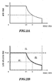
- a maximum motor torque Tmax can be generated until a vehicle speed VI is reached, when the vehicle speed V1 is exceeded, the motor torque that the motor 102 can generate decreases gradually. Namely, at vehicle speeds V that are faster than the vehicle speed V1, the motor 102 is only allowed to generate a motor torque (a maximum torque T) that is smaller than the maximum motor torque Tmax.
- Figs. 2B is a clutch application force - vehicle speed characteristic chart in which an application force that is needed to enable the transmission of motor torque is obtained from a relation between motor torque and vehicle speed in the motor torque - vehicle speed characteristic chart shown in Fig. 2A .
- the application force of the clutch CL is acquired from an application force acquiring device 104.
- the application force acquiring device 104 may be a sensor for acquiring directly an application force for the clutch CL or may be a hydraulic pressure sensor that is provided on a hydraulic circuit for driving the clutch CL or a rotation speed sensor for an oil pump for supplying a hydraulic - pressure to the hydraulic circuit, and the motor controller 108a can calculate an application force for the clutch CL from the hydraulic pressure or the rotation speed acquired from the sensors.
- the deterioration of the clutch CL that is triggered by the occurrence of a slippage in the clutch CL is prevented by prohibiting the operation of the motor 102 (stopping the motor 102) or by increasing the application force of the clutch to the necessary application force Fmax or greater to permit the operation of the motor 102.
- the motor controller 108a of this embodiment expands a range over which the motor 102 is used without increasing the application force of the clutch CL more than needed by permitting the motor 102 to operate (in the power running drive or regeneration drive) in the zone P3 in Fig. 2B .
- the motor controller 108a when receiving a request for generation of power in such a state that the motor 102 is generating no power, acquires a current motor rotation speed that is a rotation speed that the motor is currently having from the motor rotating state quantity acquiring device 103 and the current application force of the clutch CL from the application force acquiring device 104. Then, the motor controller 108a compares the necessary application force F resulting when the maximum torque T that is based on the current motor rotation speed (the vehicle speed V) of the motor 102 is generated with the current application force.
- the motor controller 108a prohibits the motor 102 from generating power in a case where the current application force is smaller than the necessary application force F, whereas in a case where the current application force is equal to or greater than the necessary application force F, the motor controller 108a permits the motor 102 to generate power without changing the application force of the clutch CL.
- the motor controller 108a acquires a current motor rotation speed that is the current rotation speed of the motor from the motor rotating state quantity acquiring device 103 and the current application force of the clutch CL from the application force acquiring device 104.Then, the motor controller 108a compares the necessary application force F resulting when the maximum torque T that is based on the current motor rotation speed (the vehicle speed V) of the motor 102 is generated with the current application force.
- the motor controller 108a prohibits the motor 102 from increasing the power in a case where the current application force is smaller than the necessary application force F, whereas in a case where the current application force is equal to or greater than the necessary application force F, the motor controller 108a permits the motor 102 to increase the power without changing the application force of the clutch CL.
- the motor controller 108a can expand the range over which the motor 102 is used wider with consumed energy kept suppressed by controlling to permit the motor 102 to generate power or increase the power and to prohibit the motor 102 from operating based on the necessary application force F resulting when the maximum torque T of the motor 102 that is based on the current motor rotation speed is generated and the current application force.
- the motor controller 108a can control to permit and/or prohibit the motor 102 from generating power and increasing the power based on the requests, irrespective of the magnitude of the requests, not only can the control be simplified, but also the response is improved.
- the motor controller 108a permits the motor 102 to operate to thereby allow the motor 102 to operate without controlling the application force of the clutch CL to exceed the necessary application force Fmax resulting when the maximum motor torque Tmax is generated which is determined according to the size of the motor 102.
- the motor controller 108a prohibits the motor 102 from operating so as to suppresses the occurrence of slippage in the clutch, thereby making it possible to prevent the deterioration in durability of the clutch CL.
- the motor controller 108a when receiving the request for generation of power in such a state that the motor 102 is generating no power, controls to permit and/or prohibit the motor 102 from generating power based on the necessary application force F and the current application force.
- the motor controller 108a acquires a maximum torque T of the motor 102 at the current motor rotation speed that is acquired from the motor rotating state quantity acquiring device 103 and acquires a transmission allowable power that is permitted to be transmitted by the current application force of the clutch CL that is acquired from the application force acquiring device 104, and controls to permit and/or prohibit the motor 102 from generating power based on the maximum torque T and the transmission allowable power.
- the motor controller 108a prohibits the motor 102 from generating power, whereas in a case where the transmission allowable power is equal to or greater than the maximum torque T, the motor controller 108a permits the motor 102 to generate power without changing the application force of the clutch CL.
- the motor controller 108a when receiving the request for an increase in power in such a state that the motor 102 is generating power, controls to permit and/or prohibit the motor 102 from increasing the power based on the necessary application force F and the current application force.
- the motor controller 108a acquires a maximum torque T of the motor 102 at the current motor rotation speed that is acquired from the motor rotating state quantity acquiring device 103 and acquires a transmission allowable power that is permitted to be transmitted by the current application force which is acquired from the application force acquiring device 104, and controls to permit and/or prohibit the motor 102 from increasing the power based on the maximum torque T and the transmission allowable power.
- the motor controller 108a prohibits the motor 102 from increasing the power, whereas in a case where the transmission allowable power is equal to or greater than the maximum torque T, the motor controller 108a permits the motor 102 to increase the power without changing the application force of the clutch CL.
- a driving system 1 employs motors as drive sources to drive axle shafts and is employed on a vehicle having a driving system as shown in Fig. 3 .
- the driving system will be described as being used to drive rear wheels. However, the driving system may be used to drive front wheels.
- a vehicle 3 shown in Fig. 3 is a hybrid electric vehicle having a driving system 6 (hereinafter, referred to as a “front wheel driving system”) in which an internal combustion engine 4 and a motor 5 are connected in series at a vehicle front portion. Power of this front driving system 6 is transmitted to front wheels Wf by way of a transmission 7, while power of a driving system 1 (hereinafter, referred to as a “rear wheel driving system”) which is provided separately from the front wheel driving system 6 at a vehicle rear portion is transmitted to rear wheels Wr (RWr, LWr).
- a driving system 6 hereinafter, referred to as a "front wheel driving system”
- a driving system 1 hereinafter, referred to as a "rear wheel driving system”
- the motor 5 of the front wheel driving system 6 and motors 2A, 2B of the rear wheel driving system 1 on the rear wheels Wr side are connected to a battery 9, so that electric power can be supplied to the motors from the battery 9, while energies generated at the driving systems can be recovered to the battery 9 for regeneration.
- Reference numeral 8 denotes a controller configured to execute various controls for the whole of the vehicle.
- Fig. 4 shows a vertical longitudinal sectional view of the whole of the rear wheel driving system 1.
- reference numerals 10A, 10B denote left and right axle shafts of the rear wheels Wr of the vehicle 3, which are disposed so as to extend coaxially in a width direction of the vehicle 3.
- a speed reducer case 11 of the rear wheel driving system 1 has a substantially cylindrical shape as a whole.
- the motors 2A, 2B configured to drive the axle shafts and planetary gear type speed reducers 12A, 12B configured to decelerate the driving rotation of the motors 2A, 2B are disposed on the axle shafts 10A, 10B coaxially therewith, respectively, in an interior of the speed reducer case 11.
- the motor 2A and the planetary gear type speed reducer 12A control a left rear wheel LWr
- the motor 2B and the planetary gear type speed reducer 12B control a right rear wheel RWr
- the motor 2A and the planetary gear type speed reducer 12A and the motor 2B and the planetary gear type speed reducer 12B are disposed laterally symmetrical with each other in the width direction within the speed reducer case 11.
- the speed reducer case 11 is supported by supporting portions 13a, 13b of a frame member 13 which makes up part of a frame which makes up, in turn, a framework of the vehicle 3 and a frame, not shown, of the rear wheel driving system 1.
- the supporting portions 13a, 13b are provided laterally symmetrical with respect to a center of the frame member 13 in the width direction.
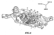
- Arrows in Fig. 6 denote positional relations with the rear wheel driving system 1 mounted on the vehicle 3.
- Respective stators 14A, 14B of the motors 2A, 2B are fixed in place inboards of left and right end sides of the speed reducer case 11, and annular rotors 15A, 15B are disposed, respectively, on inner circumferential sides of the stators 14A, 14B so as to rotate relatively to the corresponding stators 14A, 14B.
- Cylindrical shafts 16A, 16B which surround outer circumferences of the axle shafts 10A, 10B, are connected to inner circumferential portions of the rotors 15A, 15B, respectively, and the cylindrical shafts 16A, 16B are supported in end walls 17A, 17B and middle walls 18A, 18B of the speed reducer case 11 via bearings 19A, 19B so as to rotate relatively together with the axle shafts 10A and 10B.
- Resolvers 20A, 20B which functions as motor rotating state quantity acquiring devices, configured to detect rotation speeds of the rotors 15A, 15B are provided on outer circumferences of end portions of the cylindrical shafts 16A, 16B and on the end walls 17A, 17B of the speed reducer case 11.
- the planetary gear type speed reducers 12A, 12B include sun gears 21A, 21B, ring gears 24A, 24B, pluralities of planetary gears 22A, 22B which mesh with the sun gears 21A, 21B and the ring gears 24A, 24B, and planetary carriers 23A, 23B which support the planetary gears 22A, 22B, respectively. Then, motor torque that is inputted from the sun gears 21A, 21B is configured to be outputted by way of the planetary carriers 23A, 23B.
- the sun gear 21A, 21B are formed integrally with the cylindrical shafts 16A, 16B, respectively.
- the planetary gears 22A, 22B are double pinions having first pinions 26A, 26B that are greater in diameter and which mesh directly with the sun gears 21A, 21B and second pinions 27A, 27B that are smaller in diameter than the first pinions 26A, 26B.
- the first pinions 26A, 26B and the second pinions 27A, 27B are formed integrally so as not only to be coaxial but also to be offset in an axial direction.
- the planetary gears 22A, 22B are supported on the planetary carriers 23A, 23B, respectively.
- the planetary carriers 23A, 23B extend radially inwards at axial inner end portions thereof and are then spline fitted on the axle shafts 10A, 10B, respectively, so as to be supported thereon, whereby the planetary carriers 23A, 23B are supported on the axle shafts 10A, 10B so as to rotate together.
- the planetary carriers 23A, 23B are also supported on the middle walls 18A, 18B via bearings 33A, 33B.
- the middle walls 18A, 18B separate motor accommodation spaces where the motors 2A, 2B are accommodated individually from speed reducer accommodation spaces where the planetary gear type speed reducers 12A, 12B are accommodated and are formed so as to be bent or curved from a radially outer side towards a radially inner side so that an axial space defined therebetween expands.
- bearings 33A, 33B which support the planetary carriers 23A, 23B, respectively, are disposed on radially inner sides and sides facing the planetary gear type speed reducers 12A, 12B of the middle walls 18A, 18B.
- bus rings 41A, 41B for the stators 14A, 14B are disposed on radially outer sides and-sides facing the motors 2A, 2B of the middle walls 18A, 18B (refer to Fig. 4 ).
- the ring gears 24A, 24B include gear portions 28A, 28B that mesh with the second pinion gears 27A, 27B, which are smaller in diameter, on inner circumferential surfaces thereof, small diameter portions 29A, 29B that are smaller in diameter than the gear portions 28A, 28B and which are disposed so as to face each other in a middle position of the speed reducer case 11, and connecting portions 30A, 30B that connect axial inner end portions of the gear portions 28A, 28B and axial outer end portions of the small diameter portions 29A, 29B together in a radial direction.
- a maximum diameter of the ring gears 24A, 24B is set so as to be smaller than a maximum distance of the first pinions 26A, 26B from centers of the axle shafts 10A, 10B.
- the small diameter portions 29A, 29B spline fit in an inner race 51 of a one-way clutch 50, which will be described later, and the ring gears 24A, 24B rotate together with the inner race 51 of the one-way clutch 50.
- a cylindrical space portion is secured between the speed reducer case 11 and the ring gears 24A, 24B, and hydraulic brakes 60A, 60B, which make up brake devices for the ring gears 24A, 24B and function as power transmission devices, are disposed in the space portion so as to overlap the first pinions 26A, 26B in a radial direction and to overlap the second pinions 27A, 27B in an axial direction.
- pluralities of fixed plates 35A, 35B are spline fitted in an inner circumferential surface of a cylindrical radially outer support portion 34 that extends in the axial direction on a radially inner side of the speed reducer case 11, and pluralities of rotational plates 36A, 36B that are spline fitted on outer circumferential surfaces of the ring gears 24A, 24B are disposed alternately in the axial direction, respectively, and these plates 35A, 35B, 36A, 36B are operated so as to be engaged with and disengaged from each other by annular pistons 37A, 37B.
- the pistons 37A, 37B are accommodated so as to reciprocate back and forth freely in annular cylinder chambers 38A, 38B, respectively, which are defined between a laterally separating wall 39 which extends radially inwards from a middle position of the speed reducer case 11 and the radially outer support portion 34 and a radially inner support portion 40 which are connected together by the laterally separating wall 39.
- the pistons 37A, 37B are caused to move forwards or advance by introducing highly pressurized oil into the cylinder chambers 38A, 38B, and the pistons 37A, 37B are caused to move backwards or retreat by discharging the oil from the cylinder chambers 38A, 38B.
- the hydraulic brakes 60A, 60B are connected to an electric oil pump 70 that is disposed between the supporting portions 13a, 13b of the frame member 13 described above.
- the pistons 37A, 37B have first piston walls 63A, 63B and second piston walls 64A, 64B which are disposed forwards and backwards in the axial direction, and these piston walls 63A, 63B, 64A, 64B are connected together by cylindrical inner circumferential walls 65A, 65B. Consequently, annular spaces which open radially outwards are defined between the first piston walls 63A, 63B and the second piston walls 64A, 64B, and these annular spaces are partitioned laterally in the axial direction by partition members 66A, 66B which are fixed to inner circumferential surfaces of outer walls of the cylinder chambers 38A, 38B, respectively.
- Spaces defined between the laterally separating wall 39 of the speed reducer case 11 and the second piston walls 64A, 64B are made into first operation chambers S1 (refer to Fig. 7 ) into which highly pressurized oil is introduced directly, and spaces defined between the partition members 66A, 66B and the first piston walls 63A, 63B are made into second operation chambers S2 (refer to Fig. 7 ) which communicate with the first operation chambers S1 by way of through holes formed in the inner circumferential walls 65A, 65B. Spaces defined between the second piston walls 64A, 64B and the partition members 66A, 66B communicate with the atmospheric pressure.
- oil is introduced into the first operation chambers S1 and the second operation chambers S2 from a hydraulic circuit 71, which will be described later, whereby the fixed plates 35A, 35B and the rotational plates 36A, 36B are pressed against each other by means of the pressure of the oil applied to the first piston walls 63A, 63B and the second piston walls 64A, 64B. Consequently, a large pressure receiving area can be obtained by the first and second piston walls 63A, 63B, 64A, 64B which are arranged laterally in the axial direction. Therefore, a great pressing force against the fixed plates 35A, 35B and the rotational plates 36A, 36B can be obtained while restricting radial areas of the pistons 37A, 37B from being increased.
- a space portion is also ensured between the connecting portions 30A and 30B of the ring gears 24A and 24B facing each other in the axial direction.
- a one-way clutch 50 is disposed within the space portion, the one-way clutch 50 being configured to transmit only power in one direction to the ring gears 24A, 24B and to cut off power in the other direction.
- the one-way clutch 50 includes a large number of sprags 53 interposed between inner races 51 and an outer race 52, and the inner races 51 are configured to rotate together with the small diameter portions 29A and 29B of the ring gears 24A and 24B through spline fitting.
- the outer race 52 is positioned and is prevented from rotating by the radially inner support portion 40.
- the one-way clutch 50 is engaged to lock the rotation of the ring gears 24A and 24B when the vehicle 3 travels forwards by means of the power by the motors 2A and 2B.
- the one-way clutch 50 is engaged when forward rotational power of the motors 2A and 2B (rotational power by means of which the vehicle 3 is cased to travel forwards) is input into the rear wheels Wr, whereas the one-way clutch 50 is disengaged when reverse rotational power of the motors 2A and 2B is input into the rear wheels Wr.
- the one-way clutch 50 is disengaged when forward rotational power of the rear wheels Wr is input into the motors 2A and 2B, whereas the one-way clutch 50 is engaged when reverse rotational power of the rear wheels Wr is input into the motors 2A and 2B.
- the one-way clutch 50 and the hydraulic brakes 60A, 60B are provided parallel on power transmission paths between the motors 2A, 2B and the rear wheels Wr.
- the hydraulic circuit 71 can supply oil that is sucked in from a sucking port 70a that is provided in an oil pan 80 and which is discharged from the electric oil pump 70 to the first operation chambers S1 of the hydraulic brakes 60A, 60B by way of a low pressure oil path selector valve 73 and a brake oil path selector valve 74 and can supply the same oil to a lubricating and cooling portion 91 for the motors 2A, 2B and the planetary gear type speed reducers 12A, 12B by way of the low pressure oil path selector valve 73.
- the oil that is discharged from the electric oil pump 70 and is then supplied to the lubricating and cooling portion 91 for the motors 2A, 2B and the planetary gear type speed reducers 12A, 12B is reserved in the speed reducer case 11.
- Normally, lower portions of the stators of the motors 2A, 2B and lower portions of the planetary carriers 23A, 23B are situated in the oil reserved in the speed reducer case 11, and when the planetary carriers 23A, 23B rotate, the oil constitutes stirring resistance to thereby generate rotation loss.
- the electric oil pump 70 can be driven (or be operated) in at least two modes of a high-pressure mode and a low-pressure mode by a motor 90 that is made up of a position sensorless brushless direct current motor, is controlled through PID control and can control hydraulic pressures in each of those modes.
- Reference numeral 92 denotes a sensor that functions as an application force acquiring device for detecting an oil temperature and an oil or hydraulic pressure of a brake oil path 77.
- the low pressure oil path selector valve 73 is connected to a first line oil path 75a situated to face the electric oil pump 70 and making up a line oil path 75, a second line oil path 75b situated to face the brake oil path selector valve 74 and making up the line oil path 75, a first low pressure oil path 76a that communicates with the lubricating and cooling portion 91 and a second low pressure oil path 76b that communicates with the lubricating and cooling portion 91.
- the low pressure oil path selector valve 73 includes a valve body 73a that normally establishes a communication between the first line oil path 75a and the second line oil path 75b and which selectively establishes a communication between the line oil path 75 and the first low pressure oil path 76a or the second low pressure oil path 76b, a spring 73b that biases the valve body 73a in a direction (to the right in Fig. 7 ) in which a communication is established between the line oil path 75 and the first low pressure oil path 76a, and an oil chamber 73c for pressing the valve body 73a in a direction (to the left in Fig.
- valve body 73a in which a communication is established between the line oil path 75 and the second low pressure oil path 76b by means of a hydraulic pressure in the line oil path 75. Consequently, the valve body 73a is biased in the direction (to the right in Fig. 7 ) in which the communication is established between the line oil path 75 and the first low pressure oil path 76a by the spring 73b and is pressed against in the direction (to the left in Fig. 7 ) in which the communication is established between the line oil path 75 and the second low pressure oil path 76b by means of the hydraulic pressure in the line oil path 75 that is inputted into the oil chamber 73c at a right end of the low pressure oil line selector valve 73 shown in Fig. 7 .
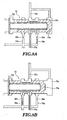
- the biasing force of the spring 73b is set so that the valve body 73a is kept stationary, whereby the line oil path 75 is cut off from the second low pressure oil path 76b and is caused to communicate with the first low pressure oil path 76a as shown in Fig. 8A (hereinafter, a position of the valve body 73a shown in Fig.
- the biasing force of the spring 73b is set so that the valve body 73a is moved, whereby the line oil path 75 is cut off from the first low pressure oil path 76a and is caused to communicate with the second low pressure oil path 76b as shown in Fig. 8B (a position of the valve body 73a shown in Fig. 8B will be referred to as a high pressure side position.).
- the brake oil path selector valve 74 is connected to the second line oil path 75b that makes up the line oil path 75, the brake oil path 77 that is connected to the hydraulic brakes 60A, 60B, and a reservoir portion 79 by way of a high position drain 78.
- the brake oil path selector valve 74 includes a valve body 74a that establishes and cuts off a communication between the second line oil path 75b and the brake oil path 77, a spring 74b that biases the valve body 74a in a direction (to the right in Fig. 7 ) in which a communication between the second line oil path 75b and the brake oil path 77 is cut off, and an oil chamber 74c for pressing the valve body 74a in a direction (to the left in Fig.
- valve body 74a in which a communication between the second line oil path-75b and the brake oil path 77 is established by means of a hydraulic pressure in the line oil path 75. Consequently, the valve body 74a.can be biased in the direction (to the right in Fig. 7 ) in which the communication is cut off between the second line oil path 75b and the brake oil path 77 by the spring 74b and can be pressed against in the direction (to the left in Fig. 7 ) in which the communication is established between the second line oil path 75b and the brake oil path 77 by means of the hydraulic pressure in the line oil path 75 that is inputted into the oil chamber 74c.
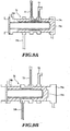
- the biasing force of the spring 74b is set so that the valve body 74a is caused to move from a valve closing position in Fig. 9A to a valve opening position in Fig. 9B by means of a hydraulic pressure in the line oil path 75 that is inputted into the oil chamber 74c while the electric oil pump 70 is being operated in the low pressure mode and the high pressure mode, whereby the brake oil path 77 is cut off from the high position drain 78 and is caused to communicate with the second line oil path 75b.
- the hydraulic pressure in the line oil path 75 that is inputted into the oil chamber 74c whether the electric oil pump 70 is operated in the low pressure mode or the high pressure mode exceeds the biasing force of the spring 74b, whereby the brake oil path 77 is cut off from the high position drain 78 and is caused to communicate with the second line oil path 75b.
- the hydraulic brakes 60A, 60B are caused to communicate with the reservoir portion 79 by way of the brake oil path 77 and the high position drain 78.
- the reservoir portion 79 is provided in a position that is higher than the oil pan 80 in a vertical direction, or more preferably, the reservoir portion 79 is provided so that a vertically uppermost portion of the reservoir portion 79 is situated in a position that is higher than a middle point in the vertical direction between a vertically uppermost portion and a vertically lowermost portion of the first operation chambers S1 of the hydraulic brakes 60A, 60B.
- oil reserved in the first operation chambers S1 of the hydraulic brakes 60A, 60B is not discharged directly into the oil pan 80 but is discharged into the reservoir portion 79 for storage therein. Oil overflowing from the reservoir portion 79 is designed to be discharged into the oil pan 80.
- a reservoir portion side end portion 78a of the high position drain 78 is connected to a bottom surface of the reservoir portion 79.
- the oil chamber 74c of the brake oil path selector valve 74 can be connected to the second line oil path 75b that makes up the line oil path 75 by way of a pilot oil path 81 and a solenoid valve 83.
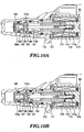
- the solenoid valve 83 is made up of a three-way solenoid valve that is controlled by the controller 8, and when a solenoid 174 (refer to Figs. 10A and 10B ) of the solenoid valve 83 is left deenergized by the controller 8, the second line oil path 75b is connected to the pilot oil path 81, so that a hydraulic pressure in the line oil path 75 is inputted into the oil chamber 74c.
- the solenoid valve 83 includes a three-way valve member 172, the solenoid 174 that is provided in a case member 173 and which receives electric power by way of a cable, not shown, to be excited, a solenoid valve body 175 that receives an exciting force of the solenoid 174 to be drawn to the right, a solenoid spring 176 that is accommodated in a spring holding recessed portion 173a that is formed in a center of the case member 173 to bias the solenoid valve body 175 to the left, and a guide member 177 that is provided within the three-way valve member 172 to guide forward and backward sliding movements of the solenoid valve body 175 therein.
- the three-way valve member 172 is a bottomed, substantially cylindrical member and has a right recessed hole 181 that is formed from a right end portion to a substantially middle portion along a center line thereof, a left recessed hole 182 that is formed from a left end portion to the vicinity of the right recessed hole 181 similarly along the center line thereof, a first radial hole 183 that is formed between the right recessed hole 181 and the left recessed hole 182 along a direction that is at right angles to the center line, a second radial hole 184 that communicates with the substantially middle portion of the right recessed hole 181 and which is formed along the direction that is at right angles to the center line, a first axial hole 185 that is formed along the center line to allow the left recessed hole 182 to communicate with the first radial hole 183, and a second axial hole 186 that is formed along the center line to allow the first radial hole 183 to communicate with the right recessed hole 181.
- a ball 187 configured to open and close the first axial hole 185, is placed in a bottom portion of the left recessed hole 182 of the three-way valve member 172 so as to move in a left-right direction
- a cap 188 configured to restrict the ball 187 from being dislocated from the left recessed hole 182, is fitted in an entrance side of the left recessed hole 182.
- a through hole 188a is formed along the center line to communicate with the first axial hole 185 in the cap 188.
- the second axial hole 186 is opened and closed as a result of a root portion of an opening and closing projection 175a that is formed at a left end portion of the solenoid valve body 175 that moves left and right being brought into disconnection therefrom and connection thereto, respectively.
- the ball 187 configured to open and close the first axial hole 185 is moved left and right by a distal end portion of the opening and closing projection 175a of the solenoid valve body 175 that moves left and right.
- the solenoid valve body 175 receives the biasing force of the solenoid spring 176 to thereby-be moved to the left, whereby the distal end portion of the opening and closing projection 175a of the solenoid valve body 175 pushes on the ball 187 to open the first axial hole 185 and the root portion of the opening and closing projection 175a of the solenoid valve body 175 is brought into contact with the second axial hole 186 to close the second axial hole 186.
- the second line oil path 75b that makes up the line oil path 75 communicates with the oil chamber 74c from the first axial hole 185 and the first radial hole 183 by way of the pilot oil path 81 (hereinafter, a position of the solenoid valve body 175 shown in Fig. 10A will be referred to as a valve opening position from time to time.).
- the solenoid valve body 175 receives the exciting force of the solenoid 174 and then moves to the right against the biasing force of the solenoid spring 176, whereby a hydraulic pressure from the through hole 188a pushes on the ball 187 to close the first axial hole 185 and the root portion of the opening and closing projection 175a of the solenoid valve body 175 moves away from the second axial hole 186 to thereby open the second axial hole 186.
- the first low pressure oil path 76a and the second low pressure oil path 76b merge together on a downstream side to make up a low pressure common path 76c, and a relief valve 84 is connected to the merging portion to reduce a hydraulic pressure in the low pressure common oil path 76c by discharging oil therein into the oil pan 80 by way of a relief drain 86 when a line pressure of the low pressure common oil path 76c reaches or exceeds a predetermined pressure.
- orifices 85a, 85b which function as flow path resistance devices, are formed on the first low pressure oil path 76a and the second low pressure oil path 76b, respectively, and the orifice 85a of the first low pressure oil path 76a is given a larger diameter than that of the orifice 85b of the second low pressure oil path 76b.
- a flow resistance in the second low pressure oil path 76b is greater than a flow resistance in the first low pressure oil path 76a, and a pressure reduction quantity in the second low pressure oil path 76b while the electric oil pump 70 is being operated in the high pressure mode becomes greater than a pressure reduction quantity in the first low pressure oil path 76a while the electric oil pump 70 is being operated in the low pressure mode, whereby the hydraulic pressures in the low pressure common oil path 76c in the high pressure mode and the low pressure mode become substantially equal.
- the low pressure oil path selector valve 73 that is connected to the first low pressure oil path 76a and the second low pressure oil path 76b in the way described above, while the electric oil pump 70 is being operated in the low pressure mode, the biasing force of the spring 73b surpasses the hydraulic pressure in the oil chamber 73c, whereby the valve body 73a is positioned in the low pressure side position by means of the biasing force of the spring 73b, and the line oil path 75 is cut off from the second low pressure oil path 76b and is caused to communicate with the first low pressure oil path 76a.
- Oil flowing through the first low pressure oil path 76a is subjected to the flow path resistance at the orifice 85a whereby the pressure thereof is reduced and then reaches the lubricating and cooling portion 91 by way of the low pressure common oil path 76c.
- the hydraulic pressure in the oil chamber 73c surpasses the biasing force of the spring 73b, whereby the valve body 73a is positioned in the high pressure side position against the biasing force of the spring 73b, and the line oil path 75 is cut off from the first low pressure oil path 76a and is caused to communicate with the second low pressure oil path 76b.
- Oil flowing through the second low pressure oil path 76b is subjected to a greater flow resistance at the orifice 85b than that at the orifice 85a whereby the pressure thereof is reduced and then reaches the lubricating and cooling portion 91 by way of the low pressure common oil path 76c.
- a plurality of orifices 85c are provided on an oil path extending from the low pressure common oil path 76c to the lubricating and cooling portion 91 as other flow path resistance devices.
- the plurality of orifices 85c are set so that a minimum flow path sectional area of the orifice 85a of the first low pressure oil path 76a becomes smaller than a minimum flow path sectional area of the plurality of orifices 85c.
- the flow path resistance of the orifice 85a of the first low pressure oil path 76a is set greater than a flow path resistance of the plurality of orifices 85c.
- the minimum flow path sectional area of the plurality of orifices 85c is a total sum of minimum flow path sectional areas of the individual orifices 85c.
- the controller 8 (refer to Fig. 3 ) is a controller that executes various controls of the whole of the vehicle, and vehicle speeds, steering angles, accelerator pedal positions AP, shift positions, SOC and fluid or oil temperatures are inputted into the controller 8, whereas a signal for controlling the internal combustion engine 4, a signal for controlling the motors 2A, 2B, signals indicating generating state, charged state and discharged state in the battery 9, a control signal to the solenoid 174 of the solenoid valve 83, and a control signal for controlling the electric oil pump 70 are outputted from the controller 8.
- the controller 8 includes at least a function as a motor controller for controlling the motors 2A, 2B and a function as a power transmission device controller for controlling the hydraulic brakes 60A, 60B that act as power transmission devices.
- the function as the motor controller is similar to that of the motor controller 108a in the first embodiment, and the function as the power transmission device controller is similar to that of the application force controller 108b in the first embodiment.
- the application force of the hydraulic brakes 60A, 60B is controlled by controlling the electric oil pump 70 and the solenoid 174 of the solenoid valve 83 as will be described herebelow.
- FIG. 7 shows the hydraulic circuit 71 in which the hydraulic brakes 60A, 60B are released with the vehicle staying at a halt.
- the controller 8 does not operate the electric oil pump 70.
- the valve body 73a of the low pressure oil path selector valve 73 is positioned in the low pressure side position, and the valve body 74a of the brake oil path selector valve 74 is positioned in the valve closing position, whereby no hydraulic pressure is supplied to the hydraulic circuit 71.
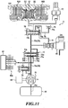
- Fig. 11 shows the hydraulic circuit 71 in which the hydraulic brakes 60A, 60B are released with the vehicle running.
- the controller 8 operates the electric oil pump 70 in the low pressure mode.
- the controller 8 energizes the solenoid 174 of the solenoid valve 83, whereby the second line oil path 75b is cut off from the pilot oil path 81.
- the valve body 74a of the brake oil path selector valve 74 is positioned in the valve closing position by means of the biasing force of the spring 74b, whereby the second line oil path 75b is cut off from the brake oil path 77 while the brake oil path 77 is caused to communicate with the high position drain 78, whereby the hydraulic brakes 60A, 60B are released.
- the brake oil path 77 is connected to the reservoir portion 79 by way of the high position drain 78.
- the valve body 73a is positioned in the low pressure side position, whereby the line oil path 75 is cut off from the second low pressure oil path 76b and is caused to communicate with the first low pressure oil path 76a.
- the pressure of oil in the line oil path 75 is reduced at the orifice 85a by way of the first low pressure oil path 76a and the oil is then supplied to the lubricating and cooling portion 91.
- Fig. 12 shows the hydraulic circuit 71 in which the hydraulic brakes 60A, 60B are weakly applied.
- the weakly applied state means a state in which although power can.be transmitted, the hydraulic brakes 60A, 60B are applied with an application force that is weaker than an application force with which the hydraulic brakes 60A, 60B are applied normally.
- the controller 8 operates the electric oil pump 70 in the low pressure mode. Additionally, the controller 8 deenergizes the solenoid 174 of the solenoid valve 83, causing the hydraulic pressure in the second line oil path 75b to be inputted into the oil chamber 74c of the brake oil path selector valve 74.
- the valve body 73a is positioned in the low pressure side position, whereby the line oil path 75 is cut off from the second low pressure oil path 76b and is caused to communicate with the first low pressure oil path 76a.
- the pressure of oil in the line oil path 75 is reduced at the orifice 85a by way of the first low pressure oil path 76a and the oil is then supplied to the lubricating and cooling portion 91.
- Fig. 13 shows the hydraulic circuit 71 in which the hydraulic brakes 60A, 60B are applied.
- the controller 8 operates the electric oil pump 70 in the high pressure mode. Additionally, the controller 8 deenergizes the solenoid 174 of the solenoid valve 83, causing the hydraulic pressure in the second line oil path 75b to be inputted into the oil chamber 74c at a right end of the brake oil path selector valve 74.
- the valve body 73a is positioned in the high pressure side position, whereby the line oil path 75 is cut off from the first low pressure oil path 76a and is caused to communicate with the second low pressure oil path 76b.
- the pressure of oil in the line oil path 75 is reduced at the orifice 85b by way of the second low pressure oil path 76b and the oil is then supplied to the lubricating and cooling portion 91.
- the controller 8 can release or apply the hydraulic brakes 60A, 60B to thereby disconnect or connect the motors 2A, 2B and the rear wheels Wr by controlling the operation mode (the operating state) of the electric oil pump 70 and the opening and closing of the solenoid valve 83 and can control the application force of the hydraulic brakes 60A, 60B.
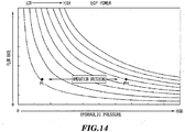
- Fig. 14 is a graph showing load characteristics of the electric oil pump 70.
- the power (work done per unit time) of the electric oil pump 70 can be reduced to of the order of one fourth to one fifth of that of the electric oil pump 70 in the high pressure mode (hydraulic pressure PH) while maintaining the flow rate of oil supplied.
- the load of the electric oil pump 70 is small, and hence, the consumed power of the motor 90 which drives the electric oil pump 70 can be reduced more than in the high pressure mode.
- Fig. 15 is a table depicting relations between the front wheel driving system 6 and the rear wheel driving system 1 in various states of the vehicle together with operating states of the motors 2A, 2B and states of the hydraulic circuit 71.
- a front unit represents the front wheel driving system 6
- a rear unit represents the rear wheel driving system 1
- a rear motor represents the motors 2A, 2B
- EOP represents the electric oil pump 70
- SOL represents the solenoid 174
- OWC represents the one-way clutch 50
- BRK represents the hydraulic brakes 60A, 60B.
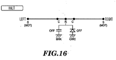
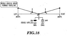
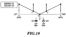
- Figs. 16 to 21 show speed collinear diagrams in various states of the rear wheel driving system 1.
- S and C on a left-hand side represent the sun gear 21A of the planetary gear type speed reducer 12A connected to the motor 2A and the planetary carrier 23A connected to the axle shaft 10A, respectively
- S and C on a right-hand side represent the sun gear 21B of the planetary gear type speed reducer 12B connected to the motor 2B and the planetary carrier 23B connected to the axle shaft 10B, respectively
- R represents the ring gears 24A, 24B
- BRK represents the hydraulic brakes 60A, 60B
- OWC represents the one-way clutch 50.
- the rotational directions of the sun gears 21A, 21B which are rotated by the motors 2A, 2B when the vehicle travels forwards will be referred to as a forward direction.
- upward motions of the sun gears and the planetary carriers from a state where the vehicle is at a halt represent forward rotations of the motors
- downward motions thereof represent reverse rotations of the motors
- upward arrows represent forward torque
- downward arrows represent reverse torque.
- a rear wheel drive is executed by the rear wheel driving system 1.
- a power running drive is executed so that the motors 2A, 2B rotate in the forward direction
- forward torque is applied to the sun gears 21A, 21B.
- the one-way clutch 50 is engaged and the ring gears 24A, 24B are locked, as has been described above. This causes the planetary carriers 23A, 23B to rotate in the forward direction, whereby the vehicle is caused to travel forwards.
- a running resistance is acting on the planetary carriers 23A, 23B in the reverse direction from the axle shafts 10A, 10B.
- the ignition switch is turned on to increase the torque of the motors 2A, 2B, whereby the one-way clutch 50 is engaged mechanically, and the ring gears 24A, 24B are locked.
- the electric oil pump 70 operates in the low pressure mode (Lo)
- the solenoid 174 of the solenoid valve 83 is left deenergized (OFF)
- the hydraulic brakes 60A, 60B are weakly applied.
- the one-way clutch 50 is engaged, and the power can be transmitted only by the one-way clutch 50.
- the hydraulic brakes 60A, 60B that are provided parallel to the one-way clutch 50 are also applied weakly to keep the motors 2A, 2B and the rear wheels Wr side in contact with each other, whereby it is possible to restrict the occurrence of a risk of no power being transmitted between the motors 2A, 2B and the rear wheels Wr even though the one-way clutch 50 is disengaged as a result of the forward torque inputted from the motors 2A, 2B being reduced temporarily.
- the application force of the hydraulic brakes 60A, 60B then becomes weaker than those resulting when the vehicle is decelerated for regeneration or is reversed. Energy to be consumed to apply the hydraulic brakes 60A, 60B is reduced by making the application force of the hydraulic brakes 60A, 60B when the one-way clutch 50 is engaged weaker than the application force of the hydraulic brakes 60A, 60B when the one-way clutch 50 is disengaged.
- the pressure of oil in the line oil path 75 is reduced at the orifice 85a by way of the first low pressure oil path 76a and the oil is then supplied to the lubricating and cooling portion 91, thereby effecting the lubrication and cooling of the constituent parts by the lubricating and cooling portion 91.
- the electric oil pump 70 operates in the low pressure mode (Lo)
- the solenoid 174 of the solenoid valve 83 is left deenergized (OFF)
- the hydraulic brakes 60A, 60B are weakly applied.
- the one-way clutch 50 is disengaged, whereby the power cannot be transmitted only by the one-way clutch 50.
- the power can still be- transmitted by causing the hydraulic brakes 60A, 60B which are provided parallel to the one-way clutch 50 to be applied weakly to thereby keep the motors 2A, 2B and the rear wheels Wr in contact with each other.
- the electric oil pump 70 operates in the high pressure mode (Hi)
- the solenoid 174 of the solenoid valve 83 is left deenergized (OFF)
- the hydraulic brakes 60A, 60B are applied (ON). Consequently, the ring gears 24A, 24B are fixed, and reverse regenerative braking torque is applied on the motors 2A, 2B, whereby a regenerative deceleration is executed by the motors 2A, 2B.
- the one-way clutch 50 is disengaged, and the power cannot be transmitted only by the one-way clutch 50.
- the power can still be transmitted by leaving the hydraulic brakes 60A, 60B which are provided in parallel to the one-way clutch 50 applied to keep the motors 2A, 2B and the rear wheels Wr in connection with each other, whereby the energy of the vehicle 3 can be recovered for regeneration by controlling the motors 2A, 2B to operate through regenerative drive.
- the pressure of oil in the line oil path 75 is reduced at the orifice 85b by way of the second low pressure oil path 76b and the oil is then supplied to the lubricating and cooling portion 91, thereby effecting the lubrication and cooling of the constituent parts by the lubricating and cooling portion 91.
- both the front wheel driving system 6 and the rear wheel driving system 1 are actuated to run the vehicle 3 through four-wheel drive.
- the rear wheel driving system 1 is in the same state as the state shown in Fig. 17 where the vehicle 3 is traveling forwards at low vehicle speeds, and the hydraulic circuit 71 is in the state shown in Fig. 12 .
- the front wheel driving system 6 functions to run the vehicle 3 through front-wheel drive.
- the motors 2A, 2B stop the power running drive, forward torque attempting to drive the vehicle forwards is applied to the planetary carriers 23A, 23B from the axle shafts 10A, 10B, respectively, and therefore, as described above, the one-way clutch 50 is disengaged.
- the electric oil pump 70 operates in the low pressure mode (Lo)
- the solenoid 174 of the solenoid valve 83 is energized (ON)
- the hydraulic brakes 60A, 60B are released (OFF). Consequently, the forced associated rotation of the motors 2A, 2B is prevented, whereby the over revolution of the motors 2A, 2B is prevented when the vehicle 3 is traveling forwards at high vehicle speeds using the front wheel driving system 6.
- the electric oil pump 70 operates in the high pressure mode (Hi)
- the solenoid 174 of the solenoid valve 83 is left deenergized (OFF)
- the hydraulic brakes 60A, 60B are applied. Consequently, the ring gears 24A, 24B are fixed, and the planetary carriers 23A, 23B are rotated in the reverse direction, whereby the vehicle is reversed.
- a running resistance is acting on the planetary carriers 23A, 23B in the forward direction from the axle shafts 10A, 10B.
- the hydraulic brakes 60A, 60B are controlled to be applied or released according to the running states of the vehicle 3, in other words, whether the motors 2A, 2B rotate in the forward direction or the reverse direction and whether the power is inputted from the motors 2A, 2B side or the rear wheels Wr side, and the application force is adjusted even when the hydraulic brakes 60A, 60B are being applied.
- Fig. 22 is a timing chart of the electric oil pump 70 (EOP), the one way clutch 50 (OWC) and the hydraulic brakes 60A, 60B (BRK) when the vehicle 3 performs from a halt state a series of actions of EV start -> EV acceleration -> first engine driving (ENG driving) -> second engine driving (ENG driving) -> regenerative deceleration -> halt.
- EOP electric oil pump 70
- OWC one way clutch 50
- BRK hydraulic brakes 60A, 60B
- oil temperatures that are detected by the sensor 92, torque of the motors 2A, 2B (motor torque) and rotation speed of the motors 2A, 2B (motor rotation speed) are shown.
- the electric oil pump 70 is kept inoperable, the one-way clutch 50 is kept disengaged (OFF) and the hydraulic brakes 60A, 60B are kept released (OFF) until the ignition switch is turned on, a shift lever is shifted from a P range to a D range, and an accelerator pedal is depressed.
- the accelerator pedal is depressed from that state, the rear wheel driving system 1 is actuated to perform the EV start and the EV acceleration through rear wheel driving.
- the electric oil pump 70 operates in the low pressure mode (Lo), the one-way clutch 50 is engaged (ON), and the hydraulic brakes 60A, 60B are weakly applied.
- the vehicle is driven through the first engine driving by the internal combustion engine 4.
- the one-way clutch 50 is disengaged (OFF)
- the electric oil pump 70 operates in the low pressure mode (Lo)
- the hydraulic brakes 60A, 60B are kept weakly applied.
- the hydraulic brakes 60A, 60B are released while the one-way clutch 50 is kept disengaged (OFF) and the electric oil pump 70 is kept operating in the low pressure mode (Lo), whereby the vehicle is driven through the second engine driving.
- the electric oil pump 70 operates in the high pressure mode (Hi) and the hydraulic brakes 60A, 60B are applied (ON) while the one-way clutch 50 is kept disengaged (OFF). Then, when the vehicle 3 comes to a halt, the electric oil pump 70 stops its operation (OFF), the one-way clutch 50 is disengaged (OFF), and the hydraulic brakes 60A, 60B are released (OFF).
- An oil temperature detected by the sensor 92 changes with time while the vehicle performs the series of driving events. This is because the oil temperature changes due to heat generated by the motors 2A, 2B, heat generated when the oil is stirred, and heat generated in association with torque transmission loss that is generated when the torque of the motors 2A, 2B is transmitted to the planetary gear type speed reducers 12A, 12B. It is seen that the application force necessary to apply the hydraulic brakes 60A, 60B weakly also changes with time to become low gradually as the oil temperature rises.
- the application force necessary to apply the hydraulic brakes 60A, 60B weakly needs to be greater than a sum of a force with which the motors 2A, 2B are forced to rotate together and a resisting force of oil that is stirred by the motors 2A, 2B and the planetary gear type speed reducers 12A, 12B.
- the resisting force of the stirred oil changes according to the viscosity of the oil. It is known that an inverse correlation exists between the viscosity of oil and temperature (oil temperature).Thus, viscosity decreases as oil temperature increases, while viscosity increases as oil temperature decreases.
- the application force of the hydraulic brakes 60A, 60B that are being applied is controlled to be weakened as the temperature of the oil increases according to the oil temperature detected by the sensor 92.
- the reliability of the hydraulic brakes 60A, 60B can be ensured by holding the application force thereof while the oil temperature remains low, whereas when the oil temperature rises, the application force is mitigated thereby making it possible to suppress an increase in consumed energy that would otherwise be caused by an excessive application force.
- the control described above may be executed not only while the hydraulic brakes 60A, 60B are being applied weakly but also while the hydraulic brakes 60A, 60B are being applied as in the case where regenerative deceleration is carried out as shown in Fig. 22 .
- the hydraulic brakes 60A, 60B functioning as the power transmission devices are configured so that the application force can be changed, whereby the power transmission capacity of the power transmission path can be changed.
- the operating state of the electric oil pump 70 is switched from the low pressure mode (Lo) to the high pressure mode (Hi), so that the application force of the hydraulic brakes 60A, 60B is increased from the application force with which the hydraulic brakes 60A, 60B are applied weakly to the application force with which the hydraulic brakes 60A, 60B are applied normally.
- the zone P3 in Fig. in the first embodiment, however, in the zone P3 in Fig.
- the controller 8 acquires current motor rotation speeds from the resolvers 20A, 20B and acquires a current application force of the clutch CL from the sensor 92.Then, the controller 8 compares the necessary application force F resulting when the maximum torque T that is based on the current motor rotation speeds of the motors 2A, 2B (the vehicle speed V) is generated with the current application force. Then, in a case the current application force is equal to or greater than the necessary application force F, the controller 8 permits the motor 102 to be driven for regeneration without changing the application force of the clutch CL.
- the motor rotation speed (the vehicle speed V) is reduced by a braking force obtained by driving the motor 102 for regeneration whereby the zone P2 in Fig. 2B is reached
- the motors 2A, 2B are caused to stop performing the regenerative drive, and wheel brakes are activated, thereby making it possible to obtain a necessary braking force.
- the controller 8 prohibits the motors 2A, 2B from performing the regenerative drive under the current application force. Then, as described in relation to Figs. 13 and 19 , the controller 8 should operate the electric oil pump 70 in the high pressure mode (Hi), deenergize the solenoid 174 of the solenoid valve 83 (OFF) and apply the hydraulic brakes 60A, 60B (ON) to thereby permit the motors 2A, 2B to perform the regenerative drive.
- Hi high pressure mode
- the solenoid 174 of the solenoid valve 83 OFF
- the hydraulic brakes 60A, 60B ON
- the controller 8 controls to permit and/or prohibit the motor 102 from performing the regenerative drive based on the necessary application force F and the current application force.
- a configuration may be adopted in which the controller 8 acquires a maximum torque T of the motors 2A, 2B at the current motor rotation speeds that are acquired from the resolvers 20A, 20B and acquires a transmission allowable power that is permitted to be transmitted by the current application force of the hydraulic brakes 60A, 60B that is acquired from the sensor 92 and controls to permit and/or prohibit the motors 2A, 2B from performing the regenerative drive based on the maximum torque T and the transmission allowable power.
- the controller 8 prohibits the motors 2A, 2B from performing the regenerative drive, whereas in a case the transmission allowable power is equal to or greater than the maximum torque T, the controller 8 permits the motors 2A, 2B to generate power without changing the application force of the hydraulic brakes 60A, 60B.
- the controller 8 controls to permit and/or prohibit the motors 2A, 2B from generating power in consideration of the current rotating state quantities of the motors 2A, 2B, thereby making it possible to expand the range over which the motors are used while suppressing the consumed energy.
- the controller 8 can-expand the range over which the motors 2A, 2B are used wider while suppressing the consumed energy than when the conventional technique is used.
- the configuration of the invention is not limited specifically as long as the invention includes a motor, wheels, and a power transmission device such as a clutch and a brake which is provided on a power transmission path between the motor and the wheels.
- the ring gears 24A, 24B do not have to be provided with the hydraulic brakes 60A, 60B, respectively, and hence, at least one hydraulic brake should be provided on the ring gears 24A, 24B which are connected together, and the one-way clutch 50 does not necessarily have to be provided.
Landscapes
- Engineering & Computer Science (AREA)
- Transportation (AREA)
- Mechanical Engineering (AREA)
- Chemical & Material Sciences (AREA)
- Combustion & Propulsion (AREA)
- Power Engineering (AREA)
- Life Sciences & Earth Sciences (AREA)
- Sustainable Development (AREA)
- Sustainable Energy (AREA)
- Electric Propulsion And Braking For Vehicles (AREA)
- Arrangement And Driving Of Transmission Devices (AREA)
- Hybrid Electric Vehicles (AREA)
Abstract
Description
- The present invention relates to a driving system which includes a motor and a power transmission device for changing a power transmission capacity of a power transmission path between the motor and wheels.
- Vehicle driving systems have conventionally been known which include a motor and a power transmission device for changing a power transmission capacity of a power transmission path between the motor and wheels. For example, in a vehicle driving system described in
Patent Literature 1, it is described that the application force of a hydraulic brake is controlled according to the viscosity of oil in consideration of the fact that an application force that is required on a hydraulic brake as a power transmission device changes according to the viscosity of oil used. - It is also described that in regeneration, a vehicle is slowed through regenerative braking by applying strongly the hydraulic brake and driving a motor for regeneration and that kinetic energy obtained is converted to electrical energy to charge the battery.
- Patent Literature 1 :
JP-A-2012-214176 - Incidentally, a size of a motor determines a maximum generation power of the motor which the motor can generate. In addition, it is generally known that the maximum generation power of a motor varies according to a rotation speed of the motor and that the maximum generation power becomes smaller as the rotation speed becomes faster. Consequently, in a motor connected to a wheel, the maximum generation power of the motor becomes smaller as the vehicle speed becomes faster.
- Conventionally, when a power running drive or a regenerative drive is executed by a motor connected to a wheel, a necessary brake application force is obtained based on a maximum generation power of the motor that is determined according to the size of the motor irrespective of a vehicle speed, and the power running drive and the regenerative drive by the motor are permitted in a zone where a brake application force exceeds the necessary brake application force. By doing so, the deterioration of a brake device is prevented by avoiding a risk of slippage taking place in the brake device as a result of the necessary brake application force that is needed when the motor generates power exceeding the brake application force.
- However, it has been desired that the motor is used over as wide a range as possible from the viewpoint of improving the fuel economy. In addition, in using the motor, when attempting to control a power transmission device to be applied with an application force that exceeds the necessary brake application force irrespective of a vehicle speed, the consumed energy by the brake device is increased to a great level.
- The invention provides a driving system which can expand a range over which a motor can be used.
- The invention provides the following aspects. According to a first aspect of the invention, there is provided a driving system (e.g., a
driving system 100/a rearwheel driving system 1 in embodiment) including: - a motor (e.g., a
motor 102/motors - a power transmission device (e.g., a clutch CL/
hydraulic brakes - a motor controller (e.g., a
motor controller 108a/acontroller 8 in embodiment) that controls power that is generated by the motor; and - an application force controller (e.g., an
application force controller 108b/acontroller 8 in embodiment) that controls the application force of the power transmission device, - wherein the driving system further includes an application force acquiring device (e.g., an application
force acquiring device 104/asensor 92 in embodiment) that acquires a current application force which is an application force that the power transmission device is currently exerting, and - wherein when the motor controller receives a request for generation of power in such a state that the motor generates no power, the motor controller controls to permit and/or prohibit the generation of power of the motor based on the current application force and a necessary application force (e.g., a necessary application force F in embodiment) which is an application force of the power transmission device that is needed to transmit a maximum generation power (e.g., a maximum torque T in embodiment) of the motor in a current rotating state quantity which is a rotating state quantity that the motor is currently having.
- According to a second aspect of the invention, in the driving system according to the first aspect,
when the current application force is smaller than the necessary application force, the generation of power of the motor is prohibited. - According to a third aspect of the invention, there is provided
a driving system (e.g., thedriving system 100/the rearwheel driving system 1 in embodiment) including: - a motor (e.g., the
motor 102/themotors - a power transmission device (e.g., the clutch CL/the
hydraulic brakes - a motor controller (e.g., the
motor controller 108a/thecontroller 8 in embodiment) that controls power that is generated by the motor; and - an application force controller (e.g., the
application force controller 108b/thecontroller 8 in embodiment) that controls the application force of the power transmission device, - wherein the driving system further includes an application force acquiring device (e.g., the application
force acquiring device 104/thesensor 92 in embodiment) that acquires a current application force which is an application force that the power transmission device is currently exerting, and - wherein when the motor controller receives a request for an increase in power in such a state that the motor is generating power, the motor controller controls to permit and/or prohibit the increase in power of the motor based on the current application force and a necessary application force (e.g., a necessary application force F in embodiment) which is an application force of the power transmission device that is needed to transmit a maximum generation power (e.g., a maximum torque T in embodiment) of the motor in a current rotating state quantity which is a rotating state quantity that the motor is currently having.
- According to a fourth aspect of the invention, in the driving system according to the third aspect,
when the current application force is smaller than the necessary application force, the increase in power of the motor is prohibited. - According to a fifth aspect of the invention, there is provided a driving system (e.g., the
driving system 100/the rear wheel driving system- 1 in embodiment) including: - a motor (e.g., the
motor 102/themotors - a power transmission device (e.g., the clutch CL/the
hydraulic brakes - a motor controller (e.g., the
motor controller 108a/thecontroller 8 in embodiment) that controls power that is generated by the motor; and - an application force controller (e.g., the
application force controller 108b/thecontroller 8 in embodiment) that controls the application force of the power transmission device, - wherein the driving system further includes an application force acquiring device (e.g., the application
force acquiring device 104/thesensor 92 in embodiment) that acquires a current application/force which is an application force that the power transmission device is currently exerting, and - wherein when the motor controller receives a request for generation of power in such a state that the motor generates no power, the motor controller controls to permit and/or prohibit the generation of power of the motor based on a maximum generation power (e.g., a maximum torque T in embodiment) of the motor in a current rotating state quantity which is a rotating state quantity that the motor is currently having and a transmission allowable, power that the current application force allows the power transmission device to transmit.
- According to a sixth aspect of the invention, in the driving system according to the fifth aspect,
when the transmission allowable power is smaller than the maximum generation power, the generation of power of the motor is prohibited. - According to a seventh aspect of the invention, there is provided a driving system (e.g., the
driving system 100/the rearwheel driving system 1 in embodiment) including: - a motor (e.g., the
motor 102/themotors - a power transmission device (e.g., the clutch CL/the
hydraulic brakes - a motor controller (e.g., the
motor controller 108a/thecontroller 8 in embodiment) that controls power that is generated by the motor; and - an application force controller (e.g., the
application force controller 108b/thecontroller 8 in embodiment) that controls the application force of the power transmission device, - wherein the driving system further includes an application force acquiring device (e.g., the application
force acquiring device 104/thesensor 92 in embodiment) that acquires a current application force which is an application force that the power transmission device is currently exerting, and - wherein when the motor controller receives a request for an increase in power in such a state that the motor is generating power, the motor controller controls to permit and/or prohibit the increase in power of the motor based on a maximum generation power (e.g., the maximum torque T in embodiment) of the motor in a current rotating state quantity which is a rotating state quantity that the motor is currently having and a transmission allowable power that the current application force allows the power transmission device to transmit.
- According to an eighth aspect of the invention, in the driving system according to the seventh aspect,
when the transmission allowable power is smaller than the maximum generation power, the increase in power is prohibited. - According to the first aspect, it is possible to expand the range over which the motor is used with consumed energy kept suppressed by controlling to permit and/or prohibit the motor from generating power in consideration of the current rotating state quantity of the motor than by using the conventional control in which the motor is permitted to generate power only over the range where the current application force of the power transmission device exceeds the necessary application force that is obtained based on the maximum generation power that is determined according to the size of the motor, irrespective of the rotating state quantity of the motor. In addition, when receiving the request for generation of power, since the motor controller can control to permit and/or prohibit the motor from generating power based on the request, irrespective of the magnitude of the request, not only can the control be simplified, but also the response is improved.
- According to the second aspect, it is possible to suppress the slippage of the power transmission device by prohibiting the motor from generating power when the current application force of the power transmission device is smaller than the necessary application force of the power transmission device that is needed to transmit the maximum generation power of the motor in the current rotating state quantity of the motor, thereby making it possible to prevent the deterioration of the durability of the power transmission device.
- According to the third aspect, it is possible to expand the range over which the motor is used with consumed energy kept suppressed by controlling to permit and/or prohibit the motor from increasing the power thereof in consideration of the current rotating state quantity of the motor than by using the conventional control in which the motor is permitted to increase the power thereof only over the range where the current application force of the power transmission device exceeds the necessary application force that is obtained based on the maximum generation power that is determined according to the size of the motor. In addition, when receiving the request for an increase in power, since the motor controller can control to permit and/or prohibit the motor from increasing the power based on the request, irrespective of the magnitude of the request, not only can the control be simplified, but also the response is improved.
- According to the fourth aspect, it is possible to suppress the slippage of the power transmission device by prohibiting the motor from increasing the power thereof when the current application force of the power transmission device is smaller than the necessary application force of the power transmission device that is needed to transmit the maximum generation power of the motor in the current rotating state quantity of the motor, thereby making it possible to prevent the deterioration of the durability of the power transmission device.
- According to the fifth aspect, it is possible to expand the range over which the motor is used with consumed energy kept suppressed by controlling to permit and/or prohibit the motor from generating power in consideration of the current rotating state quantity of the motor than by using the conventional control in which the motor is permitted to generate power only over the range where the transmission allowable power that the current application force allows to transmit exceeds the maximum generation power that is determined according to the size of the motor, irrespective of the rotating state quantity of the motor. In addition, when receiving the request for generation of power, since the motor controller can control to permit and/or prohibit the motor from generating power based on the request, irrespective of the magnitude of the request, not only can the control be simplified, but also the response is improved.
- - According to the sixth aspect, it is possible to suppress the slippage of the power transmission device by prohibiting the motor from generating power when the transmission allowable power of the power transmission device is smaller than the maximum generation power of the motor in the current rotating state quantity of the motor, thereby making it possible to prevent the deterioration of the durability.
- According to the seventh aspect, it is possible to expand the range over which the motor is used with consumed energy kept suppressed by controlling to permit and/or prohibit the motor from increasing the power thereof in consideration of the current rotating state quantity of the motor than by using the conventional control in which the motor is permitted to increase the power thereof only over the range where the transmission allowable power that the current application force allows to transmit exceeds the maximum generation power that is determined according to the size of the motor, irrespective of the rotating state quantity of the motor. In addition, when receiving the request for an increase in power, since the motor controller can control to permit and/or prohibit the motor from increasing the power based on the request, irrespective of the magnitude of the request, not only can the control be simplified, but also the response is improved.
- According to the eighth aspect, it is possible to suppress the slippage of the power transmission device by prohibiting the motor from increasing the power thereof when the transmission allowable power of the power transmission device is smaller than the maximum generation power of the motor in the current rotating state quantity of the motor, thereby making it possible to prevent the deterioration of the durability of the power transmission device.
-
-
Fig. 1 is a block diagram showing a schematic configuration of a driving system according to a first embodiment of the invention. -
Fig. 2A is a motor torque - vehicle speed characteristic chart showing a relation between motor torque and vehicle speed. -
Fig. 2B is a clutch application force - vehicle speed characteristic chart showing a relation between clutch application force and vehicle speed. -
Fig. 3 is a block diagram showing a schematic configuration of a hybrid electric vehicle that constitutes an embodiment of a vehicle on which a driving system according to a second embodiment of the invention can be mounted. -
Fig. 4 is a vertical longitudinal sectional view of a rear wheel driving system according to the second embodiment. -
Fig. 5 is a partially enlarged sectional view of the rear wheel driving system shown inFig. 4 . -
Fig. 6 is a perspective view showing a state in which the rear wheel driving system is mounted on a frame. -
Fig. 7 is a hydraulic circuit diagram of a hydraulic pressure controller for controlling hydraulic brakes and is a hydraulic circuit diagram showing a state where no hydraulic pressure is supplied. -
Fig. 8A is an explanatory diagram showing a low pressure fluid path selector valve being situated in a low pressure side position. -
Fig. 8B is an explanatory diagram showing the low pressure fluid path selector valve being situated in a high pressure side position. -
Fig. 9A is an explanatory diagram showing a brake fluid path selector valve being situated in a closed position. -
Fig. 9B is an explanatory diagram showing the brake fluid path selector valve being situated in an open position. -
Fig. 10A is an explanatory diagram showing a solenoid valve being in a non-energized state. -
Fig. 10B is an explanatory diagram showing the solenoid valve being in an energized state. -
Fig. 11 is a hydraulic circuit diagram of the hydraulic pressure controller in a state where the hydraulic brakes are released while the vehicle is running (EOP: Low pressure mode). -
Fig. 12 is a hydraulic circuit diagram of the hydraulic pressure controller in a state where the hydraulic brakes are applied weakly (EOP: Low pressure mode). -
Fig. 13 is a hydraulic circuit diagram of the hydraulic pressure controller in a state where the hydraulic brakes are applied (EOP: High pressure mode). -
Fig. 14 is a graph showing load characteristics of an electric oil pump. -
Fig. 15 is a table depicting relations between a front wheel driving system and the rear wheel driving system in various states of the vehicle together with operating states of motors and states of the hydraulic circuit. -
Fig. 16 is a speed collinear diagram of the rear wheel driving system while the vehicle is at a halt. -
Fig. 17 is a speed collinear diagram of the rear wheel driving system while the vehicle is traveling forwards at low vehicle speeds. -
Fig. 18 is a speed collinear diagram of the rear wheel driving system while the vehicle is traveling forwards at middle vehicle speeds. -
Fig. 19 is a speed collinear diagram of the rear wheel driving system while the vehicle is being decelerated for regeneration. -
Fig. 20 is a speed collinear diagram of the rear wheel driving system while the vehicle is traveling forwards at high vehicle speeds. -
Fig. 21 is a speed collinear diagram of the rear wheel driving system while the vehicle is being reversed. -
Fig. 22 is a timing chart in an example of a running of the vehicle which shows a control of an application force of the hydraulic brakes which are being applied. - Hereinafter, embodiments of a driving system according to the invention will be described based on the drawings.
- As shown in
Fig. 1 , adriving system 100 of a first embodiment has amotor 102 and a clutch CL as a power transmission device that is provided on a power transmission path between themotor 102 and a wheel W. The clutch CL is a hydraulic clutch and can change a power transmission capacity of the power transmission path by being configured so as to change an application force. - A
controller 108 of thedriving system 100 includes amotor controller 108a for controlling a generation torque of themotor 102 and anapplication force controller 108b for controlling an application force of the clutch CL. - The
application force controller 108b for controlling the application force of the clutch CL can control the application force of the clutch CL by controlling a rotation speed of an oil pump or controlling a hydraulic pressure of a hydraulic circuit. - The
motor controller 108a for controlling the generation torque of themotor 102 controls themotor 102 to be in various states such as a power running drive state, a regeneration drive state and a halt state according to a request of a crew and the like. In general, in a motor, a maximum motor torque that the motor can generate is determined by a size thereof. Further, due to its nature, the motor torque that the motor can generate decreases as the rotation speed thereof increases. Consequently, themotor controller 108a controls the motor torque based on a motor rotation speed that is acquired by a motor rotating statequantity acquiring device 103. - The motor rotating state
quantity acquiring device 103 may be a resolver that is provided on themotor 102 or may be a rotation speed sensor or a vehicle speed sensor that is provided on a rotational element (a gear, a shaft) of the power transmission path between themotor 102 and the wheel W, and themotor controller 108a can calculate a motor rotation speed from a motor rotating state quantity related to the motor rotation speed so acquired. In thedriving system 100, since themotor 102 and the wheel W are connected together by way of a pair of gears G, the motor rotation speed is proportional to the vehicle speed. - With the
motor 102 of thedriving system 100, as shown inFig. 2A , although a maximum motor torque Tmax can be generated until a vehicle speed VI is reached, when the vehicle speed V1 is exceeded, the motor torque that themotor 102 can generate decreases gradually. Namely, at vehicle speeds V that are faster than the vehicle speed V1, themotor 102 is only allowed to generate a motor torque (a maximum torque T) that is smaller than the maximum motor torque Tmax. -
Figs. 2B is a clutch application force - vehicle speed characteristic chart in which an application force that is needed to enable the transmission of motor torque is obtained from a relation between motor torque and vehicle speed in the motor torque - vehicle speed characteristic chart shown inFig. 2A . - In a zone P1 in
Fig. 2B , irrespective of vehicle speed, not only can all motor torque be theoretically transmitted to the wheel W, but also all wheel torque can theoretically be transmitted from the wheel W to themotor 102 by operating the motor 102 (in a power running drive or regeneration drive) with the clutch CL applied. This is because the application force of the clutch CL is set at an application force that is equal to or greater than a necessary application force Fmax that is needed to transmit the maximum motor torque Tmax that themotor 102 can generate according to its size. - It should be noted that the application force of the clutch CL is acquired from an application
force acquiring device 104. The applicationforce acquiring device 104 may be a sensor for acquiring directly an application force for the clutch CL or may be a hydraulic pressure sensor that is provided on a hydraulic circuit for driving the clutch CL or a rotation speed sensor for an oil pump for supplying a hydraulic - pressure to the hydraulic circuit, and themotor controller 108a can calculate an application force for the clutch CL from the hydraulic pressure or the rotation speed acquired from the sensors. - Returning to
Fig. 2B , in a zone P2 and a zone P3 inFig. 2B , even in a case where themotor 102 is operated (in the power running, drive or regeneration drive) with the clutch CL applied, since the application force of the clutch CL is smaller than the necessary application force Fmax that is needed to transmit the maximum motor torque Tmax that themotor 102 can generate according to its size, there may occur a case where all the torque cannot be transmitted between themotor 102 and the wheel W. Consequently, conventionally, in the zone P2 and the zone P3 inFig. 2B , the deterioration of the clutch CL that is triggered by the occurrence of a slippage in the clutch CL is prevented by prohibiting the operation of the motor 102 (stopping the motor 102) or by increasing the application force of the clutch to the necessary application force Fmax or greater to permit the operation of themotor 102. - In the zone P3 in
Fig. 2B , however, even though a current application force that is an application force that the clutch CL is currently exerting is less than the necessary application force Fmax with which the maximum motor torque Tmax that themotor 102 can generate according to its size can be transmitted, since the current application force is greater than a necessary application force F resulting when a maximum torque T of the motor that is based on a motor rotation speed at the current vehicle speed V is generated, all the torque can theoretically be transmitted between themotor 102 and the wheel W. - Thus, the
motor controller 108a of this embodiment expands a range over which themotor 102 is used without increasing the application force of the clutch CL more than needed by permitting themotor 102 to operate (in the power running drive or regeneration drive) in the zone P3 inFig. 2B . - Specifically speaking, when receiving a request for generation of power in such a state that the
motor 102 is generating no power, themotor controller 108a acquires a current motor rotation speed that is a rotation speed that the motor is currently having from the motor rotating statequantity acquiring device 103 and the current application force of the clutch CL from the applicationforce acquiring device 104. Then, themotor controller 108a compares the necessary application force F resulting when the maximum torque T that is based on the current motor rotation speed (the vehicle speed V) of themotor 102 is generated with the current application force. Themotor controller 108a prohibits themotor 102 from generating power in a case where the current application force is smaller than the necessary application force F, whereas in a case where the current application force is equal to or greater than the necessary application force F, themotor controller 108a permits themotor 102 to generate power without changing the application force of the clutch CL. - In addition, when receiving a request for an increase in power in such a state that the
motor 102 is generating power, themotor controller 108a acquires a current motor rotation speed that is the current rotation speed of the motor from the motor rotating statequantity acquiring device 103 and the current application force of the clutch CL from the application force acquiring device 104.Then, themotor controller 108a compares the necessary application force F resulting when the maximum torque T that is based on the current motor rotation speed (the vehicle speed V) of themotor 102 is generated with the current application force. Themotor controller 108a prohibits themotor 102 from increasing the power in a case where the current application force is smaller than the necessary application force F, whereas in a case where the current application force is equal to or greater than the necessary application force F, themotor controller 108a permits themotor 102 to increase the power without changing the application force of the clutch CL. - In this way, when compared with the conventional technique, the
motor controller 108a can expand the range over which themotor 102 is used wider with consumed energy kept suppressed by controlling to permit themotor 102 to generate power or increase the power and to prohibit themotor 102 from operating based on the necessary application force F resulting when the maximum torque T of themotor 102 that is based on the current motor rotation speed is generated and the current application force. In addition, when receiving the request for generation of power and the request for an increase in power, since themotor controller 108a can control to permit and/or prohibit themotor 102 from generating power and increasing the power based on the requests, irrespective of the magnitude of the requests, not only can the control be simplified, but also the response is improved. - Namely, when the clutch CL is applied with an application force that is smaller than the necessary application force Fmax resulting when the maximum motor torque Tmax that is determined according to the size of the
motor 102 is generated and the current application force is equal to or greater than the necessary application force F resulting when the maximum torque T of themotor 102 at the current motor rotation speed (the vehicle speed V) is generated, themotor controller 108a permits themotor 102 to operate to thereby allow themotor 102 to operate without controlling the application force of the clutch CL to exceed the necessary application force Fmax resulting when the maximum motor torque Tmax is generated which is determined according to the size of themotor 102. - Additionally, when the current application force of the clutch CL is smaller than the necessary application force F resulting when the maximum torque T of the
motor 102 that is based on the current motor rotation speed (the vehicle speed V) is generated, themotor controller 108a prohibits themotor 102 from operating so as to suppresses the occurrence of slippage in the clutch, thereby making it possible to prevent the deterioration in durability of the clutch CL. - In this embodiment, when receiving the request for generation of power in such a state that the
motor 102 is generating no power, themotor controller 108a controls to permit and/or prohibit themotor 102 from generating power based on the necessary application force F and the current application force. However, a configuration may be adopted in which themotor controller 108a acquires a maximum torque T of themotor 102 at the current motor rotation speed that is acquired from the motor rotating statequantity acquiring device 103 and acquires a transmission allowable power that is permitted to be transmitted by the current application force of the clutch CL that is acquired from the applicationforce acquiring device 104, and controls to permit and/or prohibit themotor 102 from generating power based on the maximum torque T and the transmission allowable power. Then, in a case where the transmission allowable power is smaller than the maximum torque T, themotor controller 108a prohibits themotor 102 from generating power, whereas in a case where the transmission allowable power is equal to or greater than the maximum torque T, themotor controller 108a permits themotor 102 to generate power without changing the application force of the clutch CL. - Similarly, in this embodiment, when receiving the request for an increase in power in such a state that the
motor 102 is generating power, themotor controller 108a controls to permit and/or prohibit themotor 102 from increasing the power based on the necessary application force F and the current application force. However, a configuration may be adopted in which themotor controller 108a acquires a maximum torque T of themotor 102 at the current motor rotation speed that is acquired from the motor rotating statequantity acquiring device 103 and acquires a transmission allowable power that is permitted to be transmitted by the current application force which is acquired from the applicationforce acquiring device 104, and controls to permit and/or prohibit themotor 102 from increasing the power based on the maximum torque T and the transmission allowable power. Then, in a case where the transmission allowable power is smaller than the maximum torque T, themotor controller 108a prohibits themotor 102 from increasing the power, whereas in a case where the transmission allowable power is equal to or greater than the maximum torque T, themotor controller 108a permits themotor 102 to increase the power without changing the application force of the clutch CL. - A
driving system 1 according to a second embodiment employs motors as drive sources to drive axle shafts and is employed on a vehicle having a driving system as shown inFig. 3 . In the following description, the driving system will be described as being used to drive rear wheels. However, the driving system may be used to drive front wheels. - A vehicle 3 shown in
Fig. 3 is a hybrid electric vehicle having a driving system 6 (hereinafter, referred to as a "front wheel driving system") in which aninternal combustion engine 4 and a motor 5 are connected in series at a vehicle front portion. Power of this front driving system 6 is transmitted to front wheels Wf by way of atransmission 7, while power of a driving system 1 (hereinafter, referred to as a "rear wheel driving system") which is provided separately from the front wheel driving system 6 at a vehicle rear portion is transmitted to rear wheels Wr (RWr, LWr). The motor 5 of the front wheel driving system 6 andmotors wheel driving system 1 on the rear wheels Wr side are connected to a battery 9, so that electric power can be supplied to the motors from the battery 9, while energies generated at the driving systems can be recovered to the battery 9 for regeneration.Reference numeral 8 denotes a controller configured to execute various controls for the whole of the vehicle. -
Fig. 4 shows a vertical longitudinal sectional view of the whole of the rear wheel driving system 1.InFig. 4 ,reference numerals speed reducer case 11 of the rearwheel driving system 1 has a substantially cylindrical shape as a whole. Themotors type speed reducers motors axle shafts speed reducer case 11. Themotor 2A and the planetary geartype speed reducer 12A control a left rear wheel LWr, and themotor 2B and the planetary geartype speed reducer 12B control a right rear wheel RWr, Themotor 2A and the planetary geartype speed reducer 12A and themotor 2B and the planetary geartype speed reducer 12B are disposed laterally symmetrical with each other in the width direction within thespeed reducer case 11. Then, as shown inFig. 6 , thespeed reducer case 11 is supported by supportingportions frame member 13 which makes up part of a frame which makes up, in turn, a framework of the vehicle 3 and a frame, not shown, of the rearwheel driving system 1. The supportingportions frame member 13 in the width direction. Arrows inFig. 6 denote positional relations with the rearwheel driving system 1 mounted on the vehicle 3. -
Respective stators 14A, 14B of themotors speed reducer case 11, andannular rotors stators 14A, 14B so as to rotate relatively to the correspondingstators 14A, 14B.Cylindrical shafts axle shafts rotors cylindrical shafts end walls middle walls speed reducer case 11 viabearings axle shafts Resolvers rotors cylindrical shafts end walls speed reducer case 11. - The planetary gear
type speed reducers planetary gears planetary carriers planetary gears planetary carriers - The
sun gear cylindrical shafts Fig. 5 , for example, theplanetary gears first pinions second pinions first pinions 26A, 26B.Thefirst pinions second pinions planetary gears planetary carriers planetary carriers axle shafts planetary carriers axle shafts planetary carriers middle walls bearings - The
middle walls motors type speed reducers bearings planetary carriers type speed reducers middle walls stators 14A, 14B are disposed on radially outer sides and-sides facing themotors middle walls Fig. 4 ). - The ring gears 24A, 24B include
gear portions small diameter portions gear portions speed reducer case 11, and connectingportions gear portions small diameter portions first pinions axle shafts small diameter portions inner race 51 of a one-way clutch 50, which will be described later, and the ring gears 24A, 24B rotate together with theinner race 51 of the one-way clutch 50. - Incidentally, a cylindrical space portion is secured between the
speed reducer case 11 and the ring gears 24A, 24B, andhydraulic brakes first pinions second pinions hydraulic brakes plates outer support portion 34 that extends in the axial direction on a radially inner side of thespeed reducer case 11, and pluralities ofrotational plates plates annular pistons pistons annular cylinder chambers wall 39 which extends radially inwards from a middle position of thespeed reducer case 11 and the radiallyouter support portion 34 and a radiallyinner support portion 40 which are connected together by the laterally separating wall 39.Thepistons cylinder chambers pistons cylinder chambers Fig. 6 , thehydraulic brakes electric oil pump 70 that is disposed between the supportingportions frame member 13 described above. - To describe in more detail, the
pistons first piston walls second piston walls piston walls circumferential walls first piston walls second piston walls partition members cylinder chambers wall 39 of thespeed reducer case 11 and thesecond piston walls Fig. 7 ) into which highly pressurized oil is introduced directly, and spaces defined between thepartition members first piston walls Fig. 7 ) which communicate with the first operation chambers S1 by way of through holes formed in the innercircumferential walls second piston walls partition members - In the
hydraulic brakes hydraulic circuit 71, which will be described later, whereby the fixedplates rotational plates first piston walls second piston walls second piston walls plates rotational plates pistons - In the case of these
hydraulic brakes plates outer support portion 34 which extend from thespeed reducer case 11, while therotational plates plates pistons plates plates pistons - A space portion is also ensured between the connecting
portions sprags 53 interposed betweeninner races 51 and anouter race 52, and theinner races 51 are configured to rotate together with thesmall diameter portions outer race 52 is positioned and is prevented from rotating by the radiallyinner support portion 40. The one-way clutch 50 is engaged to lock the rotation of the ring gears 24A and 24B when the vehicle 3 travels forwards by means of the power by themotors motors motors motors motors - In this way, in the rear
wheel driving system 1 of this embodiment, the one-way clutch 50 and thehydraulic brakes motors - Next, referring to
Figs. 7 to 10 , the hydraulic circuit that makes up a hydraulic pressure controller of the rearwheel driving system 1 will be described. - The
hydraulic circuit 71 can supply oil that is sucked in from a suckingport 70a that is provided in anoil pan 80 and which is discharged from theelectric oil pump 70 to the first operation chambers S1 of thehydraulic brakes path selector valve 73 and a brake oilpath selector valve 74 and can supply the same oil to a lubricating and coolingportion 91 for themotors type speed reducers path selector valve 73. The oil that is discharged from theelectric oil pump 70 and is then supplied to the lubricating and coolingportion 91 for themotors type speed reducers speed reducer case 11. Normally, lower portions of the stators of themotors planetary carriers speed reducer case 11, and when theplanetary carriers speed reducer case 11 is inclined as a result of the vehicle being turned, for example, lower portions of the rotors of themotors speed reducer case 11 to thereby generate rotation loss. - The
electric oil pump 70 can be driven (or be operated) in at least two modes of a high-pressure mode and a low-pressure mode by amotor 90 that is made up of a position sensorless brushless direct current motor, is controlled through PID control and can control hydraulic pressures in each of those modes.Reference numeral 92 denotes a sensor that functions as an application force acquiring device for detecting an oil temperature and an oil or hydraulic pressure of abrake oil path 77. - The low pressure oil
path selector valve 73 is connected to a firstline oil path 75a situated to face theelectric oil pump 70 and making up aline oil path 75, a secondline oil path 75b situated to face the brake oilpath selector valve 74 and making up theline oil path 75, a first lowpressure oil path 76a that communicates with the lubricating and coolingportion 91 and a second lowpressure oil path 76b that communicates with the lubricating and coolingportion 91. In addition, the low pressure oilpath selector valve 73 includes avalve body 73a that normally establishes a communication between the firstline oil path 75a and the secondline oil path 75b and which selectively establishes a communication between theline oil path 75 and the first lowpressure oil path 76a or the second lowpressure oil path 76b, aspring 73b that biases thevalve body 73a in a direction (to the right inFig. 7 ) in which a communication is established between theline oil path 75 and the first lowpressure oil path 76a, and anoil chamber 73c for pressing thevalve body 73a in a direction (to the left inFig. 7 ) in which a communication is established between theline oil path 75 and the second lowpressure oil path 76b by means of a hydraulic pressure in theline oil path 75. Consequently, thevalve body 73a is biased in the direction (to the right inFig. 7 ) in which the communication is established between theline oil path 75 and the first lowpressure oil path 76a by thespring 73b and is pressed against in the direction (to the left inFig. 7 ) in which the communication is established between theline oil path 75 and the second lowpressure oil path 76b by means of the hydraulic pressure in theline oil path 75 that is inputted into theoil chamber 73c at a right end of the low pressure oilline selector valve 73 shown inFig. 7 . - Here, with a hydraulic pressure in the
line oil path 75 that is inputted into theoil chamber 73c while theelectric oil pump 70 is being operated in the low pressure mode, the biasing force of thespring 73b is set so that thevalve body 73a is kept stationary, whereby theline oil path 75 is cut off from the second lowpressure oil path 76b and is caused to communicate with the first lowpressure oil path 76a as shown inFig. 8A (hereinafter, a position of thevalve body 73a shown inFig. 8B will be referred to as a low pressure side position.), and with a hydraulic pressure in theline oil path 75 that is inputted into theoil chamber 73c while theelectric oil pump 70 is being operated in the high pressure mode, the biasing force of thespring 73b is set so that thevalve body 73a is moved, whereby theline oil path 75 is cut off from the first lowpressure oil path 76a and is caused to communicate with the second lowpressure oil path 76b as shown inFig. 8B (a position of thevalve body 73a shown inFig. 8B will be referred to as a high pressure side position.). - The brake oil
path selector valve 74 is connected to the secondline oil path 75b that makes up theline oil path 75, thebrake oil path 77 that is connected to thehydraulic brakes reservoir portion 79 by way of ahigh position drain 78. The brake oilpath selector valve 74 includes avalve body 74a that establishes and cuts off a communication between the secondline oil path 75b and thebrake oil path 77, aspring 74b that biases thevalve body 74a in a direction (to the right inFig. 7 ) in which a communication between the secondline oil path 75b and thebrake oil path 77 is cut off, and anoil chamber 74c for pressing thevalve body 74a in a direction (to the left inFig. 7 ) in which a communication between the second line oil path-75b and thebrake oil path 77 is established by means of a hydraulic pressure in theline oil path 75. Consequently, the valve body 74a.can be biased in the direction (to the right inFig. 7 ) in which the communication is cut off between the secondline oil path 75b and thebrake oil path 77 by thespring 74b and can be pressed against in the direction (to the left inFig. 7 ) in which the communication is established between the secondline oil path 75b and thebrake oil path 77 by means of the hydraulic pressure in theline oil path 75 that is inputted into theoil chamber 74c. - The biasing force of the
spring 74b is set so that thevalve body 74a is caused to move from a valve closing position inFig. 9A to a valve opening position inFig. 9B by means of a hydraulic pressure in theline oil path 75 that is inputted into theoil chamber 74c while theelectric oil pump 70 is being operated in the low pressure mode and the high pressure mode, whereby thebrake oil path 77 is cut off from thehigh position drain 78 and is caused to communicate with the secondline oil path 75b. Namely, the hydraulic pressure in theline oil path 75 that is inputted into theoil chamber 74c whether theelectric oil pump 70 is operated in the low pressure mode or the high pressure mode exceeds the biasing force of thespring 74b, whereby thebrake oil path 77 is cut off from thehigh position drain 78 and is caused to communicate with the secondline oil path 75b. - With the second
line oil path 75b cut off from thebrake oil path 77, thehydraulic brakes reservoir portion 79 by way of thebrake oil path 77 and thehigh position drain 78. Here, thereservoir portion 79 is provided in a position that is higher than theoil pan 80 in a vertical direction, or more preferably, thereservoir portion 79 is provided so that a vertically uppermost portion of thereservoir portion 79 is situated in a position that is higher than a middle point in the vertical direction between a vertically uppermost portion and a vertically lowermost portion of the first operation chambers S1 of thehydraulic brakes path selector valve 74 closed, oil reserved in the first operation chambers S1 of thehydraulic brakes oil pan 80 but is discharged into thereservoir portion 79 for storage therein. Oil overflowing from thereservoir portion 79 is designed to be discharged into theoil pan 80. A reservoir portionside end portion 78a of thehigh position drain 78 is connected to a bottom surface of thereservoir portion 79. - The
oil chamber 74c of the brake oilpath selector valve 74 can be connected to the secondline oil path 75b that makes up theline oil path 75 by way of apilot oil path 81 and asolenoid valve 83. Thesolenoid valve 83 is made up of a three-way solenoid valve that is controlled by thecontroller 8, and when a solenoid 174 (refer toFigs. 10A and 10B ) of thesolenoid valve 83 is left deenergized by thecontroller 8, the secondline oil path 75b is connected to thepilot oil path 81, so that a hydraulic pressure in theline oil path 75 is inputted into theoil chamber 74c. - As shown in
Figs. 10A and 10B , thesolenoid valve 83 includes a three-way valve member 172, thesolenoid 174 that is provided in acase member 173 and which receives electric power by way of a cable, not shown, to be excited, asolenoid valve body 175 that receives an exciting force of thesolenoid 174 to be drawn to the right, asolenoid spring 176 that is accommodated in a spring holding recessedportion 173a that is formed in a center of thecase member 173 to bias thesolenoid valve body 175 to the left, and aguide member 177 that is provided within the three-way valve member 172 to guide forward and backward sliding movements of thesolenoid valve body 175 therein. - The three-
way valve member 172 is a bottomed, substantially cylindrical member and has a right recessedhole 181 that is formed from a right end portion to a substantially middle portion along a center line thereof, a left recessedhole 182 that is formed from a left end portion to the vicinity of the right recessedhole 181 similarly along the center line thereof, a firstradial hole 183 that is formed between the right recessedhole 181 and the left recessedhole 182 along a direction that is at right angles to the center line, a secondradial hole 184 that communicates with the substantially middle portion of the right recessedhole 181 and which is formed along the direction that is at right angles to the center line, a firstaxial hole 185 that is formed along the center line to allow the left recessedhole 182 to communicate with the firstradial hole 183, and a secondaxial hole 186 that is formed along the center line to allow the firstradial hole 183 to communicate with the right recessedhole 181. - In addition, a
ball 187, configured to open and close the firstaxial hole 185, is placed in a bottom portion of the left recessedhole 182 of the three-way valve member 172 so as to move in a left-right direction, and acap 188, configured to restrict theball 187 from being dislocated from the left recessedhole 182, is fitted in an entrance side of the left recessedhole 182. A throughhole 188a is formed along the center line to communicate with the firstaxial hole 185 in thecap 188. - The second
axial hole 186 is opened and closed as a result of a root portion of an opening andclosing projection 175a that is formed at a left end portion of thesolenoid valve body 175 that moves left and right being brought into disconnection therefrom and connection thereto, respectively. Theball 187 configured to open and close the firstaxial hole 185 is moved left and right by a distal end portion of the opening andclosing projection 175a of thesolenoid valve body 175 that moves left and right. - Then, in the
solenoid valve 83, when thesolenoid 174 is deenergized (no electric power is supplied to the solenoid 174), as shown inFig. 10A , thesolenoid valve body 175 receives the biasing force of thesolenoid spring 176 to thereby-be moved to the left, whereby the distal end portion of the opening andclosing projection 175a of thesolenoid valve body 175 pushes on theball 187 to open the firstaxial hole 185 and the root portion of the opening andclosing projection 175a of thesolenoid valve body 175 is brought into contact with the secondaxial hole 186 to close the secondaxial hole 186. By doing so, the secondline oil path 75b that makes up theline oil path 75 communicates with theoil chamber 74c from the firstaxial hole 185 and the firstradial hole 183 by way of the pilot oil path 81 (hereinafter, a position of thesolenoid valve body 175 shown inFig. 10A will be referred to as a valve opening position from time to time.). - In addition, when the
solenoid 174 is energized (electric power is supplied to the solenoid 174), as shown inFig. 10B , thesolenoid valve body 175 receives the exciting force of thesolenoid 174 and then moves to the right against the biasing force of thesolenoid spring 176, whereby a hydraulic pressure from the throughhole 188a pushes on theball 187 to close the firstaxial hole 185 and the root portion of the opening andclosing projection 175a of thesolenoid valve body 175 moves away from the secondaxial hole 186 to thereby open the secondaxial hole 186. By doing so, oil that is reserved in theoil chamber 74c is discharged into theoil pan 80 by way of the firstradial hole 183, the secondaxial hole 186 and the secondradial hole 184, whereby the secondline oil path 75b is cut off from the pilot oil path 81 (hereinafter, a position of thesolenoid valve body 175 shown inFig. 10B will be referred to as a valve closing position from time to time.). - Returning to
Fig. 7 , in thehydraulic circuit 71, the first lowpressure oil path 76a and the second lowpressure oil path 76b merge together on a downstream side to make up a low pressurecommon path 76c, and arelief valve 84 is connected to the merging portion to reduce a hydraulic pressure in the low pressurecommon oil path 76c by discharging oil therein into theoil pan 80 by way of arelief drain 86 when a line pressure of the low pressurecommon oil path 76c reaches or exceeds a predetermined pressure. - Here, as shown in
Figs. 8A and 8B ,orifices pressure oil path 76a and the second lowpressure oil path 76b, respectively, and theorifice 85a of the first lowpressure oil path 76a is given a larger diameter than that of theorifice 85b of the second lowpressure oil path 76b. Consequently, a flow resistance in the second lowpressure oil path 76b is greater than a flow resistance in the first lowpressure oil path 76a, and a pressure reduction quantity in the second lowpressure oil path 76b while theelectric oil pump 70 is being operated in the high pressure mode becomes greater than a pressure reduction quantity in the first lowpressure oil path 76a while theelectric oil pump 70 is being operated in the low pressure mode, whereby the hydraulic pressures in the low pressurecommon oil path 76c in the high pressure mode and the low pressure mode become substantially equal. - In the low pressure oil
path selector valve 73 that is connected to the first lowpressure oil path 76a and the second lowpressure oil path 76b in the way described above, while theelectric oil pump 70 is being operated in the low pressure mode, the biasing force of thespring 73b surpasses the hydraulic pressure in theoil chamber 73c, whereby thevalve body 73a is positioned in the low pressure side position by means of the biasing force of thespring 73b, and theline oil path 75 is cut off from the second lowpressure oil path 76b and is caused to communicate with the first lowpressure oil path 76a. Oil flowing through the first lowpressure oil path 76a is subjected to the flow path resistance at theorifice 85a whereby the pressure thereof is reduced and then reaches the lubricating and coolingportion 91 by way of the low pressurecommon oil path 76c. On the other hand, while theelectric oil pump 70 is being operated in the high pressure mode, the hydraulic pressure in theoil chamber 73c surpasses the biasing force of thespring 73b, whereby thevalve body 73a is positioned in the high pressure side position against the biasing force of thespring 73b, and theline oil path 75 is cut off from the first lowpressure oil path 76a and is caused to communicate with the second lowpressure oil path 76b. Oil flowing through the second lowpressure oil path 76b is subjected to a greater flow resistance at theorifice 85b than that at theorifice 85a whereby the pressure thereof is reduced and then reaches the lubricating and coolingportion 91 by way of the low pressurecommon oil path 76c. - Consequently, when the operation mode of the
electric oil pump 70 is switched from the low pressure mode to the high pressure mode, the oil path is automatically switched from the oil path whose flow resistance is small to the oil path whose flow path resistance is great according to a change in hydraulic pressure in theline oil path 75, and therefore, a risk is suppressed of an excessive amount of oil being supplied to the lubricating and coolingportion 91 when theelectric oil pump 70 is being operated in the high pressure mode. - In addition, a plurality of
orifices 85c are provided on an oil path extending from the low pressurecommon oil path 76c to the lubricating and coolingportion 91 as other flow path resistance devices. The plurality oforifices 85c are set so that a minimum flow path sectional area of theorifice 85a of the first lowpressure oil path 76a becomes smaller than a minimum flow path sectional area of the plurality oforifices 85c. Namely, the flow path resistance of theorifice 85a of the first lowpressure oil path 76a is set greater than a flow path resistance of the plurality oforifices 85c. As this occurs, the minimum flow path sectional area of the plurality oforifices 85c is a total sum of minimum flow path sectional areas of theindividual orifices 85c. By doing so, oil can be controlled so as to flow at a desired flow rate by theorifice 85a of the first lowpressure oil path 76a and theorifice 85b of the second lowpressure oil path 76b. - Here, the controller 8 (refer to
Fig. 3 ) is a controller that executes various controls of the whole of the vehicle, and vehicle speeds, steering angles, accelerator pedal positions AP, shift positions, SOC and fluid or oil temperatures are inputted into thecontroller 8, whereas a signal for controlling theinternal combustion engine 4, a signal for controlling themotors solenoid 174 of thesolenoid valve 83, and a control signal for controlling theelectric oil pump 70 are outputted from thecontroller 8. - Namely, the
controller 8 includes at least a function as a motor controller for controlling themotors hydraulic brakes motor controller 108a in the first embodiment, and the function as the power transmission device controller is similar to that of theapplication force controller 108b in the first embodiment. The application force of thehydraulic brakes electric oil pump 70 and thesolenoid 174 of thesolenoid valve 83 as will be described herebelow. - Next, the operation of the
hydraulic circuit 71 of the rearwheel driving system 1 will be described.
Fig. 7 shows thehydraulic circuit 71 in which thehydraulic brakes controller 8 does not operate theelectric oil pump 70. By doing so, thevalve body 73a of the low pressure oilpath selector valve 73 is positioned in the low pressure side position, and thevalve body 74a of the brake oilpath selector valve 74 is positioned in the valve closing position, whereby no hydraulic pressure is supplied to thehydraulic circuit 71. -
Fig. 11 shows thehydraulic circuit 71 in which thehydraulic brakes controller 8 operates theelectric oil pump 70 in the low pressure mode. In addition, thecontroller 8 energizes thesolenoid 174 of thesolenoid valve 83, whereby the secondline oil path 75b is cut off from thepilot oil path 81. By doing so, thevalve body 74a of the brake oilpath selector valve 74 is positioned in the valve closing position by means of the biasing force of thespring 74b, whereby the secondline oil path 75b is cut off from thebrake oil path 77 while thebrake oil path 77 is caused to communicate with thehigh position drain 78, whereby thehydraulic brakes brake oil path 77 is connected to thereservoir portion 79 by way of thehigh position drain 78. - In addition, in the low pressure oil
path selector valve 73, since the biasing force of thespring 73b is greater than the hydraulic pressure in theline oil path 75 that results while theelectric oil pump 70 is being operated in the low pressure mode and which is inputted into theoil chamber 73c at the right end in the figure, thevalve body 73a is positioned in the low pressure side position, whereby theline oil path 75 is cut off from the second lowpressure oil path 76b and is caused to communicate with the first lowpressure oil path 76a. By doing so, the pressure of oil in theline oil path 75 is reduced at theorifice 85a by way of the first lowpressure oil path 76a and the oil is then supplied to the lubricating and coolingportion 91. -
Fig. 12 shows thehydraulic circuit 71 in which thehydraulic brakes hydraulic brakes hydraulic brakes controller 8 operates theelectric oil pump 70 in the low pressure mode. Additionally, thecontroller 8 deenergizes thesolenoid 174 of thesolenoid valve 83, causing the hydraulic pressure in the secondline oil path 75b to be inputted into theoil chamber 74c of the brake oilpath selector valve 74. By doing so, the hydraulic pressure in theoil chamber 74c surpasses the biasing force of thespring 74b, and hence, thevalve body 74a is positioned in the valve opening position, whereby thebrake oil path 77 is cut off from thehigh position drain 78, while the secondline oil path 75b is caused to communicate with thebrake oil path 77, and thehydraulic brakes - In this case, too, as in the case where the
hydraulic brakes path selector valve 73, since the biasing force of thespring 73b is greater than the hydraulic pressure in theline oil path 75 that results while theelectric oil pump 70 is being operated in the low pressure mode and which is inputted into theoil chamber 73c at the right end in the figure, thevalve body 73a is positioned in the low pressure side position, whereby theline oil path 75 is cut off from the second lowpressure oil path 76b and is caused to communicate with the first lowpressure oil path 76a. By doing so, the pressure of oil in theline oil path 75 is reduced at theorifice 85a by way of the first lowpressure oil path 76a and the oil is then supplied to the lubricating and coolingportion 91. -
Fig. 13 shows thehydraulic circuit 71 in which thehydraulic brakes controller 8 operates theelectric oil pump 70 in the high pressure mode. Additionally, thecontroller 8 deenergizes thesolenoid 174 of thesolenoid valve 83, causing the hydraulic pressure in the secondline oil path 75b to be inputted into theoil chamber 74c at a right end of the brake oilpath selector valve 74. By doing so, the hydraulic pressure in theoil chamber 74c surpasses the biasing force of thespring 74b, and hence, thevalve body 74a is positioned in the valve opening position, whereby thebrake oil path 77 is cut off from thehigh position drain 78, while the secondline oil path 75b is caused to communicate with thebrake oil path 77, and thehydraulic brakes - In the low pressure oil
path selector valve 73, since the hydraulic pressure in theline oil path 75 that results while theelectric oil pump 70 is being operated in the high pressure mode and which is inputted into theoil chamber 73c at the right end in the figure is greater than the biasing force of thespring 73b, thevalve body 73a is positioned in the high pressure side position, whereby theline oil path 75 is cut off from the first lowpressure oil path 76a and is caused to communicate with the second lowpressure oil path 76b. By doing so, the pressure of oil in theline oil path 75 is reduced at theorifice 85b by way of the second lowpressure oil path 76b and the oil is then supplied to the lubricating and coolingportion 91. - In this way, the
controller 8 can release or apply thehydraulic brakes motors electric oil pump 70 and the opening and closing of thesolenoid valve 83 and can control the application force of thehydraulic brakes -
Fig. 14 is a graph showing load characteristics of theelectric oil pump 70. As shown inFig. 14 , in the low pressure mode (hydraulic pressure PL), the power (work done per unit time) of theelectric oil pump 70 can be reduced to of the order of one fourth to one fifth of that of theelectric oil pump 70 in the high pressure mode (hydraulic pressure PH) while maintaining the flow rate of oil supplied. Namely, in the low pressure mode, the load of theelectric oil pump 70 is small, and hence, the consumed power of themotor 90 which drives theelectric oil pump 70 can be reduced more than in the high pressure mode. -
Fig. 15 is a table depicting relations between the front wheel driving system 6 and the rearwheel driving system 1 in various states of the vehicle together with operating states of themotors hydraulic circuit 71. In the figure, a front unit represents the front wheel driving system 6, a rear unit represents the rearwheel driving system 1, a rear motor represents themotors electric oil pump 70, SOL represents thesolenoid 174,OWC represents the one-way clutch 50, and BRK represents thehydraulic brakes Figs. 16 to 21 show speed collinear diagrams in various states of the rearwheel driving system 1. In the figures, S and C on a left-hand side represent thesun gear 21A of the planetary geartype speed reducer 12A connected to themotor 2A and theplanetary carrier 23A connected to theaxle shaft 10A, respectively, S and C on a right-hand side represent thesun gear 21B of the planetary geartype speed reducer 12B connected to themotor 2B and theplanetary carrier 23B connected to theaxle shaft 10B, respectively, R represents the ring gears 24A, 24B, BRK represents thehydraulic brakes way clutch 50. In the following, description, the rotational directions of the sun gears 21A, 21B which are rotated by themotors - When the vehicle is at a halt, both the front wheel driving system 6 and the rear
wheel driving system 1 are not driven. Consequently, as shown inFig. 16 , themotors wheel driving system 1 are not in operation, and hence, theaxle shafts hydraulic circuit 71 inFig. 7 , theelectric oil pump 70 is not in operation, and since no hydraulic pressure is supplied although thesolenoid 174 of thesolenoid valve 83 is deenergized, thehydraulic brakes motors - Then, when the vehicle travels forwards at low vehicle speeds with good motor efficiency as in an EV start or an EV acceleration after an ignition switch is turned on, a rear wheel drive is executed by the rear
wheel driving system 1. As shown inFig. 17 , when a power running drive is executed so that themotors planetary carriers planetary carriers axle shafts motors - As this occurs, in the
hydraulic circuit 71, as shown inFig. 12 , theelectric oil pump 70 operates in the low pressure mode (Lo), thesolenoid 174 of thesolenoid valve 83 is left deenergized (OFF), and thehydraulic brakes way clutch 50. However, thehydraulic brakes motors motors motors motors hydraulic brakes hydraulic brakes hydraulic brakes hydraulic brakes line oil path 75 is reduced at theorifice 85a by way of the first lowpressure oil path 76a and the oil is then supplied to the lubricating and coolingportion 91, thereby effecting the lubrication and cooling of the constituent parts by the lubricating and coolingportion 91. - When the vehicle speed of the vehicle that is traveling forwards at low vehicle speeds is increased, causing the vehicle to travel forwards at middle vehicle speeds with good engine efficiency, the driving of the vehicle is shifted from the rear wheel driving by the rear
wheel driving system 1 to the front wheel driving by the front wheel driving system 6. As shown inFig. 18 , when themotors planetary carriers axle shafts - As this occurs, in the
hydraulic circuit 71, as shown inFig. 12 , theelectric oil pump 70 operates in the low pressure mode (Lo), thesolenoid 174 of thesolenoid valve 83 is left deenergized (OFF), and thehydraulic brakes motors way clutch 50. However, the power can still be- transmitted by causing thehydraulic brakes motors hydraulic brakes line oil path 75 is reduced at theorifice 85a by way of the first lowpressure oil path 76a and the oil is then supplied to the lubricating and coolingportion 91, thereby effecting the lubrication and cooling of the constituent parts by the lubricating and coolingportion 91. - When attempting to drive the
motors Fig. 17 or18 , as shown inFig. 19 , the forward torque attempting to keep the vehicle traveling forwards is applied to theplanetary carriers axle shafts - As this occurs, in the
hydraulic circuit 71, as shown inFig. 13 , theelectric oil pump 70 operates in the high pressure mode (Hi), thesolenoid 174 of thesolenoid valve 83 is left deenergized (OFF), and thehydraulic brakes motors motors motors way clutch 50. However, the power can still be transmitted by leaving thehydraulic brakes motors motors line oil path 75 is reduced at theorifice 85b by way of the second lowpressure oil path 76b and the oil is then supplied to the lubricating and coolingportion 91, thereby effecting the lubrication and cooling of the constituent parts by the lubricating and coolingportion 91. - Following this, in accelerating the vehicle, both the front wheel driving system 6 and the rear
wheel driving system 1 are actuated to run the vehicle 3 through four-wheel drive. In this state, the rearwheel driving system 1 is in the same state as the state shown inFig. 17 where the vehicle 3 is traveling forwards at low vehicle speeds, and thehydraulic circuit 71 is in the state shown inFig. 12 . - In running the vehicle 3 forwards at high vehicle speeds, the front wheel driving system 6 functions to run the vehicle 3 through front-wheel drive. As shown in
Fig. 20 , when themotors planetary carriers axle shafts - As this occurs, in the
hydraulic circuit 71, as shown inFig. 11 , theelectric oil pump 70 operates in the low pressure mode (Lo), thesolenoid 174 of thesolenoid valve 83 is energized (ON), and thehydraulic brakes motors motors line oil path 75 is reduced at theorifice 85a by way of the first lowpressure oil path 76a and the oil is then supplied to the lubricating and coolingportion 91, thereby effecting the lubrication and cooling of the constituent parts by the lubricating and coolingportion 91. - In reversing the vehicle, as shown in
Fig. 21 , when themotors - As this occurs, in the
hydraulic circuit 71, as shown inFig. 13 , theelectric oil pump 70 operates in the high pressure mode (Hi), thesolenoid 174 of thesolenoid valve 83 is left deenergized (OFF), and thehydraulic brakes planetary carriers planetary carriers axle shafts motors way clutch 50. However, the power can still be transmitted by leaving thehydraulic brakes motors motors line oil path 75 is reduced at theorifice 85b by way of the second lowpressure oil path 76b and the oil is then supplied to the lubricating and coolingportion 91, thereby effecting the lubrication and cooling of the constituent parts by the lubricating and coolingportion 91. - In this way, in the rear
wheel driving system 1, thehydraulic brakes motors motors hydraulic brakes -
Fig. 22 is a timing chart of the electric oil pump 70 (EOP), the one way clutch 50 (OWC) and thehydraulic brakes Fig. 22 , oil temperatures that are detected by thesensor 92, torque of themotors motors - Firstly, the
electric oil pump 70 is kept inoperable, the one-way clutch 50 is kept disengaged (OFF) and thehydraulic brakes wheel driving system 1 is actuated to perform the EV start and the EV acceleration through rear wheel driving. As this occurs, theelectric oil pump 70 operates in the low pressure mode (Lo), the one-way clutch 50 is engaged (ON), and thehydraulic brakes - Then, when the driving of the vehicle is shifted from the rear wheel driving to the front wheel driving as a result of the vehicle speed reaching the middle vehicle speed range from the low vehicle speed range, the vehicle is driven through the first engine driving by the
internal combustion engine 4. As this occurs, the one-way clutch 50 is disengaged (OFF), theelectric oil pump 70 operates in the low pressure mode (Lo), and thehydraulic brakes hydraulic brakes electric oil pump 70 is kept operating in the low pressure mode (Lo), whereby the vehicle is driven through the second engine driving. Then, when the brake pedal is depressed, for example, to decelerate the vehicle for regeneration, theelectric oil pump 70 operates in the high pressure mode (Hi) and thehydraulic brakes electric oil pump 70 stops its operation (OFF), the one-way clutch 50 is disengaged (OFF), and thehydraulic brakes - An oil temperature detected by the
sensor 92 changes with time while the vehicle performs the series of driving events. This is because the oil temperature changes due to heat generated by themotors motors type speed reducers hydraulic brakes hydraulic brakes motors motors type speed reducers - The resisting force of the stirred oil changes according to the viscosity of the oil. It is known that an inverse correlation exists between the viscosity of oil and temperature (oil temperature).Thus, viscosity decreases as oil temperature increases, while viscosity increases as oil temperature decreases.
- Consequently, while the vehicle performs the series of driving events shown in
Fig. 22 , the application force of thehydraulic brakes sensor 92. By doing so, the reliability of thehydraulic brakes hydraulic brakes hydraulic brakes Fig. 22 . - In this way, the
hydraulic brakes - In the above description, when the vehicle is decelerated so that the energy thereof is recovered for regeneration, the operating state of the
electric oil pump 70 is switched from the low pressure mode (Lo) to the high pressure mode (Hi), so that the application force of thehydraulic brakes hydraulic brakes hydraulic brakes Fig. 2B , even though the current application force is less than the necessary application force Fmax with which the maximum motor torque Tmax that themotors hydraulic brakes motors motors - Consequently, when the vehicle runs in the way shown in
Fig. 22 , in a case where the current application force of thehydraulic brakes motors hydraulic brakes motors hydraulic brakes - zSpecifically speaking, when a request is made for a regenerative drive of the
motors controller 8 acquires current motor rotation speeds from theresolvers controller 8 compares the necessary application force F resulting when the maximum torque T that is based on the current motor rotation speeds of themotors controller 8 permits themotor 102 to be driven for regeneration without changing the application force of the clutch CL. - In a case where the motor rotation speed (the vehicle speed V) is reduced by a braking force obtained by driving the
motor 102 for regeneration whereby the zone P2 inFig. 2B is reached, themotors - When the current application force of the clutch CL is less than the necessary application force F, the
controller 8 prohibits themotors Figs. 13 and19 , thecontroller 8 should operate theelectric oil pump 70 in the high pressure mode (Hi), deenergize thesolenoid 174 of the solenoid valve 83 (OFF) and apply thehydraulic brakes motors - In this embodiment, the
controller 8 controls to permit and/or prohibit themotor 102 from performing the regenerative drive based on the necessary application force F and the current application force. However, a configuration may be adopted in which thecontroller 8 acquires a maximum torque T of themotors resolvers hydraulic brakes sensor 92 and controls to permit and/or prohibit themotors controller 8 prohibits themotors controller 8 permits themotors hydraulic brakes - Thus, as has been described heretofore, in this embodiment, too, the
controller 8 controls to permit and/or prohibit themotors motors controller 8 can-expand the range over which themotors - The invention is not limited to the embodiment that has been described heretofore and hence can be modified or improved as required.
- The configuration of the invention is not limited specifically as long as the invention includes a motor, wheels, and a power transmission device such as a clutch and a brake which is provided on a power transmission path between the motor and the wheels.
- For example, in the second embodiment, the ring gears 24A, 24B do not have to be provided with the
hydraulic brakes - This patent application is based on Japanese Patent Application (No.
2016-067853) filed on March 30, 2016 -
- 1
- Rear wheel driving system
- 2A, 2B, 102
- Motor
- 8
- controller (Motor controller, Application force controller)
- 60A, 60B
- Hydraulic brake (power transmission device)
- 92
- Sensor (Application force acquiring device)
- 100
- Driving system
- 104
- Application force acquiring device
- 108a
- Motor controller
- 108b
- Application force controller
- CL
- Clutch (power transmission device)
- LWr, RWr
- Rear wheel (wheel)
- W
- Wheel
Claims (8)
- A driving system comprising:a motor that is connected to a wheel of a vehicle so as to transmit power to the wheel;a power transmission device that is provided on a power transmission path between the motor and the wheel and that can change a power transmission capacity of the power transmission path by controlling an application force;a motor controller that controls power that is generated by the motor; andan application force controller that controls the application force of the power transmission device,wherein the driving system further comprises an application force acquiring device that acquires a current application force which is an application force that the power transmission device is currently exerting, andwherein when the motor controller receives a request for generation of power in such a state that the motor generates no power, the motor controller controls to permit and/or prohibit the generation of power of the motor based on the current application force and a necessary application force which is an application force of the power transmission device that is needed to transmit a maximum generation power of the motor in a current rotating state quantity which is a rotating state quantity that the motor is currently having.
- The driving system according to claim 1,
wherein when the current application force is smaller than the necessary application force, the generation of power of the motor is prohibited. - A driving system comprising:a motor that is connected to a wheel of a vehicle so as to transmit power to the wheel;a power transmission device that is provided on a power transmission path between the motor and the wheel and that can change a power transmission capacity of the power transmission path by controlling an application force;a motor controller that controls power that is generated by the motor; andan application force controller that controls the application force of the power transmission device,wherein the driving system further comprises an application force acquiring device that acquires a current application force which is an application force that the power transmission device is currently exerting, andwherein when the motor controller receives a request for an increase in power in such a state that the motor is generating power, the motor controller controls to permit and/or prohibit the increase in power of the motor based on the current application force and a necessary application force which is an application force of the power transmission device that is needed to transmit a maximum generation power of the motor in a current rotating state quantity which is a rotating state quantity that the motor is currently having.
- The driving system according to claim 3,
wherein when the current application force is smaller than the necessary application force, the increase in power of the motor is prohibited: - A driving system comprising:a motor that is connected to a wheel of a vehicle so as to transmit power to the wheel;a power transmission device that is provided on a power transmission path between the motor and the wheel and that can change a power transmission capacity of the power transmission path by controlling an application force;a motor controller that controls power that is generated by the motor; andan application force controller that controls the application force of the power transmission device,wherein the driving system further comprises an application force acquiring device that acquires a current application force which is an application force that the power transmission device is currently exerting, andwherein when the motor controller receives a request for generation of power in such a state that the motor generates no power, the motor controller controls to permit and/or prohibit the generation of power of the motor based on a maximum generation power of the motor in a current rotating state quantity which is a rotating state quantity that the motor is currently having and a transmission allowable power that the power transmission device can transmit in the current application force.
- The driving system according to claim 5,
wherein when the transmission allowable power is smaller than the maximum generation power, the generation of power of the motor is prohibited. - A driving system comprising:a motor that is connected to a wheel of a vehicle so as to transmit power to the wheel;a power transmission device that is provided on a power transmission path between the motor and the wheel and that can change a power transmission capacity of the power transmission path by controlling an application force;a motor controller that controls power that is generated by the motor; andan application force controller that controls the application force of the power transmission device,wherein the driving system further comprises an application force acquiring device that acquires a current application force which is an application force that the power transmission device is currently exerting, andwherein when the motor controller receives a request for an increase in power in such a state that the motor is generating power, the motor controller controls to permit and/or prohibit the increase in power of the motor based on a maximum generation power of the motor in a current rotating state quantity which is a rotating state quantity that the motor is currently having and a transmission allowable power that the power transmission device can transmit in the current application force.
- The driving system according to claim 7,
wherein when the transmission allowable power is smaller than the maximum generation power, the increase in power is prohibited.
Applications Claiming Priority (2)
| Application Number | Priority Date | Filing Date | Title |
|---|---|---|---|
| JP2016067853A JP6118932B1 (en) | 2016-03-30 | 2016-03-30 | Drive device |
| PCT/JP2017/012465 WO2017170442A1 (en) | 2016-03-30 | 2017-03-27 | Drive device |
Publications (3)
| Publication Number | Publication Date |
|---|---|
| EP3401156A1 true EP3401156A1 (en) | 2018-11-14 |
| EP3401156A4 EP3401156A4 (en) | 2019-01-16 |
| EP3401156B1 EP3401156B1 (en) | 2020-10-07 |
Family
ID=58666939
Family Applications (1)
| Application Number | Title | Priority Date | Filing Date |
|---|---|---|---|
| EP17774979.3A Not-in-force EP3401156B1 (en) | 2016-03-30 | 2017-03-27 | Drive device |
Country Status (5)
| Country | Link |
|---|---|
| US (1) | US10112474B2 (en) |
| EP (1) | EP3401156B1 (en) |
| JP (1) | JP6118932B1 (en) |
| CN (1) | CN108778824B (en) |
| WO (1) | WO2017170442A1 (en) |
Families Citing this family (1)
| Publication number | Priority date | Publication date | Assignee | Title |
|---|---|---|---|---|
| US20250033449A1 (en) * | 2021-11-26 | 2025-01-30 | Valeo Embrayages | Rear-wheel drive system for a mobility vehicle |
Family Cites Families (22)
| Publication number | Priority date | Publication date | Assignee | Title |
|---|---|---|---|---|
| KR100534683B1 (en) * | 2002-09-05 | 2005-12-07 | 현대자동차주식회사 | Method of protecting a shock of the motor in a hybrid vehicle |
| JP3817516B2 (en) * | 2002-12-26 | 2006-09-06 | 本田技研工業株式会社 | Drive control apparatus for hybrid vehicle |
| US8335623B2 (en) * | 2007-10-25 | 2012-12-18 | GM Global Technology Operations LLC | Method and apparatus for remediation of and recovery from a clutch slip event in a hybrid powertrain system |
| US8187145B2 (en) * | 2007-10-25 | 2012-05-29 | GM Global Technology Operations LLC | Method and apparatus for clutch torque control in mode and fixed gear for a hybrid powertrain system |
| US8296027B2 (en) * | 2007-10-25 | 2012-10-23 | GM Global Technology Operations LLC | Method and apparatus to control off-going clutch torque during torque phase for a hybrid powertrain system |
| US8282526B2 (en) * | 2007-10-29 | 2012-10-09 | GM Global Technology Operations LLC | Method and apparatus to create a pseudo torque phase during oncoming clutch engagement to prevent clutch slip for a hybrid powertrain system |
| US8414449B2 (en) * | 2007-11-04 | 2013-04-09 | GM Global Technology Operations LLC | Method and apparatus to perform asynchronous shifts with oncoming slipping clutch torque for a hybrid powertrain system |
| US8221285B2 (en) * | 2007-11-04 | 2012-07-17 | GM Global Technology Operations LLC | Method and apparatus to offload offgoing clutch torque with asynchronous oncoming clutch torque, engine and motor torque for a hybrid powertrain system |
| US8285432B2 (en) * | 2007-11-05 | 2012-10-09 | GM Global Technology Operations LLC | Method and apparatus for developing a control architecture for coordinating shift execution and engine torque control |
| DE112009005050B4 (en) * | 2009-07-09 | 2015-05-13 | Toyota Jidosha Kabushiki Kaisha | Fuel cell system and control method for this |
| JP5222329B2 (en) * | 2010-08-05 | 2013-06-26 | 本田技研工業株式会社 | Braking device for vehicle |
| JP5414636B2 (en) * | 2010-08-24 | 2014-02-12 | 本田技研工業株式会社 | Vehicle drive device |
| JP2012214176A (en) * | 2011-04-01 | 2012-11-08 | Honda Motor Co Ltd | Vehicle drive device |
| JP5641149B2 (en) * | 2011-09-28 | 2014-12-17 | トヨタ自動車株式会社 | Control device for vehicle drive device |
| JP5854052B2 (en) * | 2011-10-21 | 2016-02-09 | トヨタ自動車株式会社 | Vehicle control device |
| EP2940348B1 (en) * | 2012-12-26 | 2019-02-27 | Nissan Motor Co., Ltd | Eletric vehicle gearshift control method and device |
| US9623867B2 (en) * | 2013-04-26 | 2017-04-18 | Nissan Motor Co., Ltd. | Clutch control device for hybrid vehicle |
| JP5775113B2 (en) * | 2013-06-11 | 2015-09-09 | 本田技研工業株式会社 | Control device for automatic transmission |
| EP3085593A4 (en) * | 2013-12-17 | 2017-12-06 | Honda Motor Co., Ltd. | Vehicle |
| MY181770A (en) * | 2013-12-27 | 2021-01-06 | Honda Motor Co Ltd | Vehicle |
| JP6155211B2 (en) * | 2014-03-10 | 2017-06-28 | 本田技研工業株式会社 | Vehicle drive device and vehicle drive method |
| KR101592416B1 (en) * | 2014-06-02 | 2016-02-05 | 현대자동차주식회사 | Apparatus and method for controlling clutch of hybrid vehicle |
-
2016
- 2016-03-30 JP JP2016067853A patent/JP6118932B1/en active Active
-
2017
- 2017-03-27 WO PCT/JP2017/012465 patent/WO2017170442A1/en not_active Ceased
- 2017-03-27 EP EP17774979.3A patent/EP3401156B1/en not_active Not-in-force
- 2017-03-27 US US15/562,061 patent/US10112474B2/en active Active
- 2017-03-27 CN CN201780018823.9A patent/CN108778824B/en active Active
Also Published As
| Publication number | Publication date |
|---|---|
| JP2017184443A (en) | 2017-10-05 |
| EP3401156B1 (en) | 2020-10-07 |
| EP3401156A4 (en) | 2019-01-16 |
| JP6118932B1 (en) | 2017-04-19 |
| US20180194216A1 (en) | 2018-07-12 |
| US10112474B2 (en) | 2018-10-30 |
| CN108778824A (en) | 2018-11-09 |
| WO2017170442A1 (en) | 2017-10-05 |
| CN108778824B (en) | 2019-06-21 |
Similar Documents
| Publication | Publication Date | Title |
|---|---|---|
| EP2610526B1 (en) | Liquid flow path control device for drive device for vehicle | |
| EP2610516B1 (en) | Vehicle drive device | |
| RU2492068C1 (en) | Transport facility | |
| KR101684729B1 (en) | Drive device for vehicle | |
| US9387847B2 (en) | Front-and rear-wheel-drive vehicle | |
| EP3088238B1 (en) | Drive device for transportation machine | |
| JP5344771B2 (en) | vehicle | |
| US8768551B2 (en) | Vehicle driving apparatus | |
| JP5600633B2 (en) | Vehicle drive device and vehicle | |
| JP5414731B2 (en) | vehicle | |
| EP3401156B1 (en) | Drive device | |
| JP2012214176A (en) | Vehicle drive device | |
| JP5520993B2 (en) | Vehicle drive device | |
| CA2934437C (en) | Driving system for vehicle | |
| JP5850641B2 (en) | vehicle | |
| JP5247776B2 (en) | Hydraulic control device for vehicle drive device | |
| JP2012217302A (en) | Vehicle drive device | |
| JP5883690B2 (en) | Vehicle drive device | |
| JP2017184442A (en) | Driving device | |
| JP2013199978A (en) | Power device |
Legal Events
| Date | Code | Title | Description |
|---|---|---|---|
| STAA | Information on the status of an ep patent application or granted ep patent |
Free format text: STATUS: THE INTERNATIONAL PUBLICATION HAS BEEN MADE |
|
| PUAI | Public reference made under article 153(3) epc to a published international application that has entered the european phase |
Free format text: ORIGINAL CODE: 0009012 |
|
| STAA | Information on the status of an ep patent application or granted ep patent |
Free format text: STATUS: REQUEST FOR EXAMINATION WAS MADE |
|
| 17P | Request for examination filed |
Effective date: 20180807 |
|
| AK | Designated contracting states |
Kind code of ref document: A1 Designated state(s): AL AT BE BG CH CY CZ DE DK EE ES FI FR GB GR HR HU IE IS IT LI LT LU LV MC MK MT NL NO PL PT RO RS SE SI SK SM TR |
|
| AX | Request for extension of the european patent |
Extension state: BA ME |
|
| A4 | Supplementary search report drawn up and despatched |
Effective date: 20181214 |
|
| RIC1 | Information provided on ipc code assigned before grant |
Ipc: B60W 20/10 20160101ALI20181210BHEP Ipc: B60K 6/44 20071001ALI20181210BHEP Ipc: B60L 11/18 20060101ALI20181210BHEP Ipc: B60L 7/18 20060101ALI20181210BHEP Ipc: B60W 10/02 20060101ALI20181210BHEP Ipc: B60K 7/00 20060101ALI20181210BHEP Ipc: B60K 17/356 20060101ALI20181210BHEP Ipc: B60K 17/354 20060101ALI20181210BHEP Ipc: B60K 6/48 20071001ALI20181210BHEP Ipc: B60K 17/04 20060101ALI20181210BHEP Ipc: B60K 6/52 20071001ALI20181210BHEP Ipc: B60L 15/20 20060101AFI20181210BHEP Ipc: B60L 11/14 20060101ALI20181210BHEP Ipc: B60W 10/08 20060101ALI20181210BHEP Ipc: B60L 11/00 20060101ALI20181210BHEP |
|
| RIC1 | Information provided on ipc code assigned before grant |
Ipc: B60L 11/18 20060101ALI20181210BHEP Ipc: B60W 20/10 20160101ALI20181210BHEP Ipc: B60K 17/356 20060101ALI20181210BHEP Ipc: B60K 7/00 20060101ALI20181210BHEP Ipc: B60L 15/20 20060101AFI20181210BHEP Ipc: B60W 10/02 20060101ALI20181210BHEP Ipc: B60K 6/52 20071001ALI20181210BHEP Ipc: B60K 17/04 20060101ALI20181210BHEP Ipc: B60L 11/14 20060101ALI20181210BHEP Ipc: B60L 11/00 20060101ALI20181210BHEP Ipc: B60K 6/48 20071001ALI20181210BHEP Ipc: B60W 10/08 20060101ALI20181210BHEP Ipc: B60K 6/44 20071001ALI20181210BHEP Ipc: B60K 17/354 20060101ALI20181210BHEP Ipc: B60L 7/18 20060101ALI20181210BHEP |
|
| STAA | Information on the status of an ep patent application or granted ep patent |
Free format text: STATUS: EXAMINATION IS IN PROGRESS |
|
| DAV | Request for validation of the european patent (deleted) | ||
| DAX | Request for extension of the european patent (deleted) | ||
| 17Q | First examination report despatched |
Effective date: 20190627 |
|
| GRAP | Despatch of communication of intention to grant a patent |
Free format text: ORIGINAL CODE: EPIDOSNIGR1 |
|
| STAA | Information on the status of an ep patent application or granted ep patent |
Free format text: STATUS: GRANT OF PATENT IS INTENDED |
|
| RIC1 | Information provided on ipc code assigned before grant |
Ipc: B60W 10/08 20060101ALI20200331BHEP Ipc: B60W 10/02 20060101ALI20200331BHEP Ipc: B60L 15/20 20060101AFI20200331BHEP Ipc: B60L 7/18 20060101ALI20200331BHEP Ipc: B60K 6/44 20071001ALI20200331BHEP Ipc: B60K 17/354 20060101ALI20200331BHEP Ipc: B60K 7/00 20060101ALI20200331BHEP Ipc: B60K 17/04 20060101ALI20200331BHEP Ipc: B60K 6/52 20071001ALI20200331BHEP Ipc: B60W 20/10 20160101ALI20200331BHEP Ipc: B60K 6/48 20071001ALI20200331BHEP Ipc: B60K 17/356 20060101ALI20200331BHEP |
|
| INTG | Intention to grant announced |
Effective date: 20200429 |
|
| GRAS | Grant fee paid |
Free format text: ORIGINAL CODE: EPIDOSNIGR3 |
|
| GRAA | (expected) grant |
Free format text: ORIGINAL CODE: 0009210 |
|
| STAA | Information on the status of an ep patent application or granted ep patent |
Free format text: STATUS: THE PATENT HAS BEEN GRANTED |
|
| AK | Designated contracting states |
Kind code of ref document: B1 Designated state(s): AL AT BE BG CH CY CZ DE DK EE ES FI FR GB GR HR HU IE IS IT LI LT LU LV MC MK MT NL NO PL PT RO RS SE SI SK SM TR |
|
| REG | Reference to a national code |
Ref country code: GB Ref legal event code: FG4D |
|
| REG | Reference to a national code |
Ref country code: CH Ref legal event code: EP Ref country code: AT Ref legal event code: REF Ref document number: 1320831 Country of ref document: AT Kind code of ref document: T Effective date: 20201015 |
|
| REG | Reference to a national code |
Ref country code: DE Ref legal event code: R096 Ref document number: 602017025131 Country of ref document: DE |
|
| REG | Reference to a national code |
Ref country code: IE Ref legal event code: FG4D |
|
| REG | Reference to a national code |
Ref country code: NL Ref legal event code: MP Effective date: 20201007 |
|
| REG | Reference to a national code |
Ref country code: AT Ref legal event code: MK05 Ref document number: 1320831 Country of ref document: AT Kind code of ref document: T Effective date: 20201007 |
|
| PG25 | Lapsed in a contracting state [announced via postgrant information from national office to epo] |
Ref country code: FI Free format text: LAPSE BECAUSE OF FAILURE TO SUBMIT A TRANSLATION OF THE DESCRIPTION OR TO PAY THE FEE WITHIN THE PRESCRIBED TIME-LIMIT Effective date: 20201007 Ref country code: PT Free format text: LAPSE BECAUSE OF FAILURE TO SUBMIT A TRANSLATION OF THE DESCRIPTION OR TO PAY THE FEE WITHIN THE PRESCRIBED TIME-LIMIT Effective date: 20210208 Ref country code: RS Free format text: LAPSE BECAUSE OF FAILURE TO SUBMIT A TRANSLATION OF THE DESCRIPTION OR TO PAY THE FEE WITHIN THE PRESCRIBED TIME-LIMIT Effective date: 20201007 Ref country code: NO Free format text: LAPSE BECAUSE OF FAILURE TO SUBMIT A TRANSLATION OF THE DESCRIPTION OR TO PAY THE FEE WITHIN THE PRESCRIBED TIME-LIMIT Effective date: 20210107 Ref country code: GR Free format text: LAPSE BECAUSE OF FAILURE TO SUBMIT A TRANSLATION OF THE DESCRIPTION OR TO PAY THE FEE WITHIN THE PRESCRIBED TIME-LIMIT Effective date: 20210108 |
|
| REG | Reference to a national code |
Ref country code: LT Ref legal event code: MG4D |
|
| PG25 | Lapsed in a contracting state [announced via postgrant information from national office to epo] |
Ref country code: BG Free format text: LAPSE BECAUSE OF FAILURE TO SUBMIT A TRANSLATION OF THE DESCRIPTION OR TO PAY THE FEE WITHIN THE PRESCRIBED TIME-LIMIT Effective date: 20210107 Ref country code: IS Free format text: LAPSE BECAUSE OF FAILURE TO SUBMIT A TRANSLATION OF THE DESCRIPTION OR TO PAY THE FEE WITHIN THE PRESCRIBED TIME-LIMIT Effective date: 20210207 Ref country code: LV Free format text: LAPSE BECAUSE OF FAILURE TO SUBMIT A TRANSLATION OF THE DESCRIPTION OR TO PAY THE FEE WITHIN THE PRESCRIBED TIME-LIMIT Effective date: 20201007 Ref country code: PL Free format text: LAPSE BECAUSE OF FAILURE TO SUBMIT A TRANSLATION OF THE DESCRIPTION OR TO PAY THE FEE WITHIN THE PRESCRIBED TIME-LIMIT Effective date: 20201007 Ref country code: SE Free format text: LAPSE BECAUSE OF FAILURE TO SUBMIT A TRANSLATION OF THE DESCRIPTION OR TO PAY THE FEE WITHIN THE PRESCRIBED TIME-LIMIT Effective date: 20201007 Ref country code: AT Free format text: LAPSE BECAUSE OF FAILURE TO SUBMIT A TRANSLATION OF THE DESCRIPTION OR TO PAY THE FEE WITHIN THE PRESCRIBED TIME-LIMIT Effective date: 20201007 Ref country code: ES Free format text: LAPSE BECAUSE OF FAILURE TO SUBMIT A TRANSLATION OF THE DESCRIPTION OR TO PAY THE FEE WITHIN THE PRESCRIBED TIME-LIMIT Effective date: 20201007 |
|
| PG25 | Lapsed in a contracting state [announced via postgrant information from national office to epo] |
Ref country code: HR Free format text: LAPSE BECAUSE OF FAILURE TO SUBMIT A TRANSLATION OF THE DESCRIPTION OR TO PAY THE FEE WITHIN THE PRESCRIBED TIME-LIMIT Effective date: 20201007 Ref country code: NL Free format text: LAPSE BECAUSE OF FAILURE TO SUBMIT A TRANSLATION OF THE DESCRIPTION OR TO PAY THE FEE WITHIN THE PRESCRIBED TIME-LIMIT Effective date: 20201007 |
|
| REG | Reference to a national code |
Ref country code: DE Ref legal event code: R097 Ref document number: 602017025131 Country of ref document: DE |
|
| PG25 | Lapsed in a contracting state [announced via postgrant information from national office to epo] |
Ref country code: RO Free format text: LAPSE BECAUSE OF FAILURE TO SUBMIT A TRANSLATION OF THE DESCRIPTION OR TO PAY THE FEE WITHIN THE PRESCRIBED TIME-LIMIT Effective date: 20201007 Ref country code: SK Free format text: LAPSE BECAUSE OF FAILURE TO SUBMIT A TRANSLATION OF THE DESCRIPTION OR TO PAY THE FEE WITHIN THE PRESCRIBED TIME-LIMIT Effective date: 20201007 Ref country code: SM Free format text: LAPSE BECAUSE OF FAILURE TO SUBMIT A TRANSLATION OF THE DESCRIPTION OR TO PAY THE FEE WITHIN THE PRESCRIBED TIME-LIMIT Effective date: 20201007 Ref country code: LT Free format text: LAPSE BECAUSE OF FAILURE TO SUBMIT A TRANSLATION OF THE DESCRIPTION OR TO PAY THE FEE WITHIN THE PRESCRIBED TIME-LIMIT Effective date: 20201007 Ref country code: CZ Free format text: LAPSE BECAUSE OF FAILURE TO SUBMIT A TRANSLATION OF THE DESCRIPTION OR TO PAY THE FEE WITHIN THE PRESCRIBED TIME-LIMIT Effective date: 20201007 Ref country code: EE Free format text: LAPSE BECAUSE OF FAILURE TO SUBMIT A TRANSLATION OF THE DESCRIPTION OR TO PAY THE FEE WITHIN THE PRESCRIBED TIME-LIMIT Effective date: 20201007 |
|
| PLBE | No opposition filed within time limit |
Free format text: ORIGINAL CODE: 0009261 |
|
| STAA | Information on the status of an ep patent application or granted ep patent |
Free format text: STATUS: NO OPPOSITION FILED WITHIN TIME LIMIT |
|
| REG | Reference to a national code |
Ref country code: DE Ref legal event code: R084 Ref document number: 602017025131 Country of ref document: DE |
|
| PG25 | Lapsed in a contracting state [announced via postgrant information from national office to epo] |
Ref country code: DK Free format text: LAPSE BECAUSE OF FAILURE TO SUBMIT A TRANSLATION OF THE DESCRIPTION OR TO PAY THE FEE WITHIN THE PRESCRIBED TIME-LIMIT Effective date: 20201007 |
|
| 26N | No opposition filed |
Effective date: 20210708 |
|
| PG25 | Lapsed in a contracting state [announced via postgrant information from national office to epo] |
Ref country code: MC Free format text: LAPSE BECAUSE OF FAILURE TO SUBMIT A TRANSLATION OF THE DESCRIPTION OR TO PAY THE FEE WITHIN THE PRESCRIBED TIME-LIMIT Effective date: 20201007 Ref country code: IT Free format text: LAPSE BECAUSE OF FAILURE TO SUBMIT A TRANSLATION OF THE DESCRIPTION OR TO PAY THE FEE WITHIN THE PRESCRIBED TIME-LIMIT Effective date: 20201007 Ref country code: AL Free format text: LAPSE BECAUSE OF FAILURE TO SUBMIT A TRANSLATION OF THE DESCRIPTION OR TO PAY THE FEE WITHIN THE PRESCRIBED TIME-LIMIT Effective date: 20201007 |
|
| REG | Reference to a national code |
Ref country code: CH Ref legal event code: PL |
|
| GBPC | Gb: european patent ceased through non-payment of renewal fee |
Effective date: 20210327 |
|
| PG25 | Lapsed in a contracting state [announced via postgrant information from national office to epo] |
Ref country code: SI Free format text: LAPSE BECAUSE OF FAILURE TO SUBMIT A TRANSLATION OF THE DESCRIPTION OR TO PAY THE FEE WITHIN THE PRESCRIBED TIME-LIMIT Effective date: 20201007 |
|
| REG | Reference to a national code |
Ref country code: BE Ref legal event code: MM Effective date: 20210331 |
|
| PG25 | Lapsed in a contracting state [announced via postgrant information from national office to epo] |
Ref country code: LI Free format text: LAPSE BECAUSE OF NON-PAYMENT OF DUE FEES Effective date: 20210331 Ref country code: LU Free format text: LAPSE BECAUSE OF NON-PAYMENT OF DUE FEES Effective date: 20210327 Ref country code: CH Free format text: LAPSE BECAUSE OF NON-PAYMENT OF DUE FEES Effective date: 20210331 Ref country code: IE Free format text: LAPSE BECAUSE OF NON-PAYMENT OF DUE FEES Effective date: 20210327 Ref country code: GB Free format text: LAPSE BECAUSE OF NON-PAYMENT OF DUE FEES Effective date: 20210327 Ref country code: FR Free format text: LAPSE BECAUSE OF NON-PAYMENT OF DUE FEES Effective date: 20210331 |
|
| PG25 | Lapsed in a contracting state [announced via postgrant information from national office to epo] |
Ref country code: IS Free format text: LAPSE BECAUSE OF FAILURE TO SUBMIT A TRANSLATION OF THE DESCRIPTION OR TO PAY THE FEE WITHIN THE PRESCRIBED TIME-LIMIT Effective date: 20210207 |
|
| PG25 | Lapsed in a contracting state [announced via postgrant information from national office to epo] |
Ref country code: BE Free format text: LAPSE BECAUSE OF NON-PAYMENT OF DUE FEES Effective date: 20210331 |
|
| PGFP | Annual fee paid to national office [announced via postgrant information from national office to epo] |
Ref country code: DE Payment date: 20230131 Year of fee payment: 7 |
|
| PG25 | Lapsed in a contracting state [announced via postgrant information from national office to epo] |
Ref country code: CY Free format text: LAPSE BECAUSE OF FAILURE TO SUBMIT A TRANSLATION OF THE DESCRIPTION OR TO PAY THE FEE WITHIN THE PRESCRIBED TIME-LIMIT Effective date: 20201007 |
|
| PG25 | Lapsed in a contracting state [announced via postgrant information from national office to epo] |
Ref country code: HU Free format text: LAPSE BECAUSE OF FAILURE TO SUBMIT A TRANSLATION OF THE DESCRIPTION OR TO PAY THE FEE WITHIN THE PRESCRIBED TIME-LIMIT; INVALID AB INITIO Effective date: 20170327 |
|
| PG25 | Lapsed in a contracting state [announced via postgrant information from national office to epo] |
Ref country code: MK Free format text: LAPSE BECAUSE OF FAILURE TO SUBMIT A TRANSLATION OF THE DESCRIPTION OR TO PAY THE FEE WITHIN THE PRESCRIBED TIME-LIMIT Effective date: 20201007 |
|
| PG25 | Lapsed in a contracting state [announced via postgrant information from national office to epo] |
Ref country code: TR Free format text: LAPSE BECAUSE OF FAILURE TO SUBMIT A TRANSLATION OF THE DESCRIPTION OR TO PAY THE FEE WITHIN THE PRESCRIBED TIME-LIMIT Effective date: 20201007 |
|
| PG25 | Lapsed in a contracting state [announced via postgrant information from national office to epo] |
Ref country code: MT Free format text: LAPSE BECAUSE OF FAILURE TO SUBMIT A TRANSLATION OF THE DESCRIPTION OR TO PAY THE FEE WITHIN THE PRESCRIBED TIME-LIMIT Effective date: 20201007 |
|
| REG | Reference to a national code |
Ref country code: DE Ref legal event code: R119 Ref document number: 602017025131 Country of ref document: DE |
|
| PG25 | Lapsed in a contracting state [announced via postgrant information from national office to epo] |
Ref country code: DE Free format text: LAPSE BECAUSE OF NON-PAYMENT OF DUE FEES Effective date: 20241001 |
|
| PG25 | Lapsed in a contracting state [announced via postgrant information from national office to epo] |
Ref country code: DE Free format text: LAPSE BECAUSE OF NON-PAYMENT OF DUE FEES Effective date: 20241001 |