EP3401134B1 - Leveling valve for discharging and supplying fluid - Google Patents
Leveling valve for discharging and supplying fluid Download PDFInfo
- Publication number
- EP3401134B1 EP3401134B1 EP17000787.6A EP17000787A EP3401134B1 EP 3401134 B1 EP3401134 B1 EP 3401134B1 EP 17000787 A EP17000787 A EP 17000787A EP 3401134 B1 EP3401134 B1 EP 3401134B1
- Authority
- EP
- European Patent Office
- Prior art keywords
- air
- damping element
- leveling valve
- valve
- exhaust
- Prior art date
- Legal status (The legal status is an assumption and is not a legal conclusion. Google has not performed a legal analysis and makes no representation as to the accuracy of the status listed.)
- Active
Links
Images



Classifications
-
- B—PERFORMING OPERATIONS; TRANSPORTING
- B60—VEHICLES IN GENERAL
- B60G—VEHICLE SUSPENSION ARRANGEMENTS
- B60G17/00—Resilient suspensions having means for adjusting the spring or vibration-damper characteristics, for regulating the distance between a supporting surface and a sprung part of vehicle or for locking suspension during use to meet varying vehicular or surface conditions, e.g. due to speed or load
- B60G17/02—Spring characteristics, e.g. mechanical springs and mechanical adjusting means
- B60G17/04—Spring characteristics, e.g. mechanical springs and mechanical adjusting means fluid spring characteristics
- B60G17/052—Pneumatic spring characteristics
- B60G17/0523—Regulating distributors or valves for pneumatic springs
-
- B—PERFORMING OPERATIONS; TRANSPORTING
- B60—VEHICLES IN GENERAL
- B60G—VEHICLE SUSPENSION ARRANGEMENTS
- B60G17/00—Resilient suspensions having means for adjusting the spring or vibration-damper characteristics, for regulating the distance between a supporting surface and a sprung part of vehicle or for locking suspension during use to meet varying vehicular or surface conditions, e.g. due to speed or load
- B60G17/02—Spring characteristics, e.g. mechanical springs and mechanical adjusting means
- B60G17/04—Spring characteristics, e.g. mechanical springs and mechanical adjusting means fluid spring characteristics
- B60G17/052—Pneumatic spring characteristics
- B60G17/0523—Regulating distributors or valves for pneumatic springs
- B60G17/0525—Height adjusting or levelling valves
-
- B—PERFORMING OPERATIONS; TRANSPORTING
- B60—VEHICLES IN GENERAL
- B60G—VEHICLE SUSPENSION ARRANGEMENTS
- B60G17/00—Resilient suspensions having means for adjusting the spring or vibration-damper characteristics, for regulating the distance between a supporting surface and a sprung part of vehicle or for locking suspension during use to meet varying vehicular or surface conditions, e.g. due to speed or load
- B60G17/02—Spring characteristics, e.g. mechanical springs and mechanical adjusting means
- B60G17/04—Spring characteristics, e.g. mechanical springs and mechanical adjusting means fluid spring characteristics
- B60G17/056—Regulating distributors or valves for hydropneumatic systems
-
- B—PERFORMING OPERATIONS; TRANSPORTING
- B60—VEHICLES IN GENERAL
- B60G—VEHICLE SUSPENSION ARRANGEMENTS
- B60G17/00—Resilient suspensions having means for adjusting the spring or vibration-damper characteristics, for regulating the distance between a supporting surface and a sprung part of vehicle or for locking suspension during use to meet varying vehicular or surface conditions, e.g. due to speed or load
- B60G17/02—Spring characteristics, e.g. mechanical springs and mechanical adjusting means
- B60G17/04—Spring characteristics, e.g. mechanical springs and mechanical adjusting means fluid spring characteristics
- B60G17/056—Regulating distributors or valves for hydropneumatic systems
- B60G17/0565—Height adjusting valves
-
- F—MECHANICAL ENGINEERING; LIGHTING; HEATING; WEAPONS; BLASTING
- F16—ENGINEERING ELEMENTS AND UNITS; GENERAL MEASURES FOR PRODUCING AND MAINTAINING EFFECTIVE FUNCTIONING OF MACHINES OR INSTALLATIONS; THERMAL INSULATION IN GENERAL
- F16K—VALVES; TAPS; COCKS; ACTUATING-FLOATS; DEVICES FOR VENTING OR AERATING
- F16K11/00—Multiple-way valves, e.g. mixing valves; Pipe fittings incorporating such valves
- F16K11/02—Multiple-way valves, e.g. mixing valves; Pipe fittings incorporating such valves with all movable sealing faces moving as one unit
- F16K11/06—Multiple-way valves, e.g. mixing valves; Pipe fittings incorporating such valves with all movable sealing faces moving as one unit comprising only sliding valves, i.e. sliding closure elements
- F16K11/072—Multiple-way valves, e.g. mixing valves; Pipe fittings incorporating such valves with all movable sealing faces moving as one unit comprising only sliding valves, i.e. sliding closure elements with pivoted closure members
- F16K11/074—Multiple-way valves, e.g. mixing valves; Pipe fittings incorporating such valves with all movable sealing faces moving as one unit comprising only sliding valves, i.e. sliding closure elements with pivoted closure members with flat sealing faces
-
- F—MECHANICAL ENGINEERING; LIGHTING; HEATING; WEAPONS; BLASTING
- F16—ENGINEERING ELEMENTS AND UNITS; GENERAL MEASURES FOR PRODUCING AND MAINTAINING EFFECTIVE FUNCTIONING OF MACHINES OR INSTALLATIONS; THERMAL INSULATION IN GENERAL
- F16K—VALVES; TAPS; COCKS; ACTUATING-FLOATS; DEVICES FOR VENTING OR AERATING
- F16K47/00—Means in valves for absorbing fluid energy
- F16K47/02—Means in valves for absorbing fluid energy for preventing water-hammer or noise
-
- B—PERFORMING OPERATIONS; TRANSPORTING
- B60—VEHICLES IN GENERAL
- B60G—VEHICLE SUSPENSION ARRANGEMENTS
- B60G2500/00—Indexing codes relating to the regulated action or device
- B60G2500/20—Spring action or springs
- B60G2500/202—Height or leveling valve for air-springs
Definitions
- the present invention relates to a leveling valve for discharging and supplying air from and to a plurality of utilization elements, in particular pneumatic suspension bellows, the leveling valve comprising: a valve arrangement for directing air between a source of pressurized air, an exhaust port and said utilization elements, and a supply port in fluid communication with the valve arrangement and the source of pressurized air, and an exhaust port having an exhaust air channel for discharging exhaust air.
- Leveling valves of the aforementioned type are for example known from WO 2010/089089 or EP 2 806 194 A1 .
- Leveling valves of the known type are used to regulate the vertical clearance of a vehicle such as a truck or other utility vehicle with respect to ground level.
- a vehicle such as a truck or other utility vehicle with respect to ground level.
- the utilization elements such as pneumatic suspension bellows of a vehicle
- it is in certain situations necessary to increase or decrease the suspension level of the utilization elements. This is achieved by switching the leveling valve, in particular the valve arrangement, from its neutral position to either an "exhaust" switching position or an "air supply” switching position.
- air will be exhausted from the utilization elements into the atmosphere, or will be supplied to the utilization elements from a source of pressurized air.
- the leveling valve known from WO 2010/089089 focuses on ways of decreasing the number of sealing elements used inside a valve by making a non-rotatable valve disc axially movable inside a valve housing, wherein the two valve discs are pressed against each other by pressure prevailing in either a line connected to the source of pressurized air or in a line connected to the utilization elements.
- US 4,886,092 discloses a leveling valve responsive to changes in vertical distance between a vehicle chassis and its axle.
- the leveling valve includes an internal chamber in which a piston reciprocates.
- the piston includes a passage. In a first position of the piston, the valve is closed. In a second position of the piston, a supply port is in communication with one or more delivery ports. In a third position of the piston, the supply port is closed and the delivery port or ports are in communication with an exhaust port through the passage of the piston.
- a felt air filter can be supported near an end of the exhaust port by a perforated plastic cap.
- US 3,162,433 discloses a leveling valve mechanism including a passage open to the atmosphere and having an air silencer such as steel-wool or glass body arranged therein.
- the passage serves as an exhaust port.
- EP 2 806 194 focuses on providing an improved leveling valve with better reactivity when switched and with less noise emission.
- EP 2 806 194 suggests to employ rotatable valve discs for controlling the effective flow cross-section in a flow path between a source of pressurized air or the exhausted port in said utilization elements.
- a good reactivity of the valve is achieved at low rotation angles, while the acoustic noise of the valve is reduced by means of the comparatively shallow increase at higher rotation angles of the rotatable valve discs.
- the object of the invention is achieved according to one aspect with a leveling valve according to claim 1.
- the leveling valve according to invention has an exhaust port comprising at least one air-permeable damping element, which is at least partly positioned within the exhaust air channel, the damping element having the shape of a ring.
- the air-permeable damping element is configured for reducing the emission of noise from the exhaust port to the environment of the leveling valve.
- the invention is based upon the idea that positioning of an air permeable element through which the pressurized air can flow reduces the noise emission during the flow of exhaust air through the exhaust air port.
- the necessary adaptations to integrate such air permeable damping element into the exhaust port are relatively simple, such that the noise emission reduction according to the invention is available with low efforts and relatively low cost.
- the damping element comprises or consists of a textile material, preferably felt, wool felt, plastic felt, nonwovens or textile mesh. These materials are robust and durable and effective as a damper element for reducing noise emission from the exhaust port. Further, these materials, depending on their specific properties, have the capability to filter out particles or oil from the exhaust air flow. Particularly preferred is the material wool felt, since it combines good damping qualities and durability.
- the damping element has a density of 0.19 +/- 0.1 [g/cm3], to the advantageous effect that the noise reduction is efficient and the flow resistance of the damping element relatively low.
- the damping element has an air-permeability in the range between 190 - 210 [L/min], preferably 200 [L/min]. This improves the air flow resistance.
- the damping element has an oil absorption capability in the range between 360-420 %.
- the damping element has the shape of a cylindrical ring having a cylindrical through bore, wherein preferably the inner diameter of the cylindrical through bore is in the range between 6 - 8 mm, preferably 7.5 mm. This design ensures a stable position of the damping element within the exhaust air channel over a long period of time.
- the damping element has an outer diameter in the range between 15 - 19 [mm], preferably 17 [mm] and/or a length, measured in the direction of the flow within the exhaust air channel, in the range between 8 - 12 [mm], preferably 10 [mm].
- the damping element is positioned within a tubular recess within the housing of the valve, so that the damping element for reducing noise emission is safely integrated within the housing so that no further parts need to be attached to the housing of a valve.
- the damping element is positioned within a protruding, preferably tubular sleeve extension section connected with the housing of the leveling valve.
- This design alternative is also relatively simple as regards of the construction and allows a retrofit of the noise reducing damping element to an existing housing.
- the damping element is positioned upstream of an air flap and/or a washer element within the exhaust air channel, so that the noise reducing damping element is safely positioned and controls the exhaust gas flow through the exhaust port together with the flap.
- the damping element is positioned around a central positioning element extending through an axial bore of the damping element and being positioned centrally within the exhaust air channel, and wherein the damping element is positioned within a tubular sleeve or tubular section of the housing of the leveling valve, and/or
- the invention relates to an air suspension system for use in a vehicle, in particular for use in a commercial vehicle.
- the air suspension system comprises a plurality of utilization elements, in particular suspension bellows, a leveling valve for discharging and supplying air from and to said utilization elements, and a source of pressurized air connected to a supply port of said leveling valve.
- the invention achieves the object described hereinabove by providing a leveling valve according to any one of the preferred embodiments described hereinabove in the air suspension system.
- the invention relates to a vehicle, in particular commercial vehicle, comprising a plurality of tyres mounted on a vehicle axle, a super structure and an air suspension system axle coupling the axle to the super structure, wherein the air suspension system is an air suspension system as described hereinabove.
- the leveling valve 101 comprises a valve arrangement 103 for directing air between (as shown in Fig. 5 ) a plurality of utilization elements 205a,b and either a source 207 of pressurized air or an exhaust port 3.
- the valve arrangement 103 is preferably a valve disc arrangement. It comprises a first valve disc 107 and a second valve disc 109.
- the first and second valve discs 107, 109 of the valve arrangement 103 comprise respective flow portions forming flow paths for guiding the air through the valve.
- the first and second valve discs 107, 109 are rotatable with respect to each other.
- the first valve disc 107 is mounted to be stationary inside a housing 140 of the leveling valve 101.
- the second valve disc 109 is mounted to be rotatable inside the housing 140.
- the housing 140 of the leveling valve 101 comprises a base body 141.
- the first valve disc 107 is mounted non-rotatably inside that base body 141.
- the housing 140 further comprises a rotatable housing part 145 which is fastened to the base body 141 by way of a housing lid 148 and extends into the base body 141.
- a resilient means for example in the form of a spring 147, is located and effective to push the second valve disc 109 towards the first valve disc 107 in order to establish a sealing, preferably air-tight relationship between the valve discs 107, 109 of the valve arrangement 103 and the housing, in particular with respect to the base body 141 of the housing 140 - this is also clearly visible in Fig. 2 .
- the base body 141 of the housing 140 comprises (as shown in Fig. 5 ) a first fluid channel 21 at the end of which there is located a connector 142a for connecting the leveling valve 101 and in particular the first fluid channel 21 to a utilization element 205a of a vehicle (as shown in Fig. 5 ).
- said base body 141 comprises a second fluid channel 22. At the end of the second fluid channel 22 there is located a connector 142b for connecting the leveling valve 101 to a second utilization element 205b.
- Utilization elements 205a,b may for example be pneumatic suspension bellows of a truck vehicle, wherein the first utilization element 205a might be right side suspension bellow of a vehicle whereas the second utilization element 205b might be the left side suspension bellow of the vehicle, or vice versa.
- the fluid channels 21, 22 are connected to respective flow portions in the first valve disc 107 of the valve arrangement 103.
- the rotating portion 145 of the housing 140 comprises an external mounting section which in Fig. 1a receives a lever 143 for operating the valve 101.
- the lever comprises at its --in Fig. 1a -- rightmost end portion a coupling means 150 engage a portion of the vehicle.
- Mechanical elements for translating a control motion from the vehicle to the valve 101 may be rollers, steering rods, etc..
- the rotatable housing portion 145 is rotated relative to the base body 141 of the housing 140.
- the second valve disc 109 of the valve arrangement 103 is mounted non-rotatably with respect to the rotatable housing portion 145.
- the second valve disc 109 is rotated relative to the first valve disc 107 in this embodiment.
- the leveling valve 101 may optionally comprise a throttle 115a or 115c.
- Fig. 1a exemplarily shows throttle 115a which formed as a flow passage in the shape of a conical bore in the base body 141, connecting the first and second fluid channels 21, 22 with each other.
- the fluid flow into and out of the leveling valve 101 are best seen from Fig. 1a ; this is why in regard to reference signs, explicit reference is made to Fig. 1a and the air flow into and out of leveling valve 101 is accomplished as will be apparent hereinafter.
- the leveling valve 101 comprises in its base body 141 a fluid supply port 1.
- the fluid supply port 1 is in air-tight sealing contact with the first valve disc 107 and in fluid communication with a first air passage 117 in the first valve disc 107.
- the fluid supply port 1 also comprises a connector 142c similar to connectors 142a,b (shown in Fig. 5 ) also shown in Fig. 1a , which lead to the utilization elements 205a,b.
- Connector 142c is adapted for connection to a source 207 of pressurized air.
- the fluid supply port 1 Adjacent the connector 142c, the fluid supply port 1 houses a check valve 5 comprising a lip seal 7, wherein the lip seal 7 is configured to allow fluid flow inwards, towards the valve arrangement 103, and which is configured to prevent flow outwards, meaning from the valve arrangement 103 towards the source of pressurized air 207.
- the check valve 5 is mounted directly adjacent the connector 142c and extends in a first elongate section 9, as e.g. shown in Fig. 1b .
- the lip seal 7 abuts against a wall 13 of the fluid supply port 1 in the first elongate section 9.
- the fluid supply port 1 comprises a second elongate section 11 in which the connector 142c is mounted.
- a transition zone 10 which comprises a conically tapered section.
- a sealing element 12 may be arranged in between the check valve 5 and the connector 142c.
- pressurized air can be supplied through the first air passage 117 into a first flow portion 125 of the first valve disc 107 ( Fig. 1 a) .
- air will be transported in fluid communication through a crosslink portion 137 of the second valve disc 109 to second and third air passages 119, 121 in the first valve disc and from there to the first and second fluid channels 21, 22 which lead towards the utilization elements 205a,b.
- air is being transported through the fluid channels 21, 22 and the second and third air passages 119, 121 of the first valve disc 107 into the second valve disc 109, through a second flow portion 127 in the second valve disc 109 and from there to a fourth air passage 123 in the first valve disc 107.
- the fourth air passage 123 in the first valve disc 107 is fluid communication with a second air plenum 156.
- the check valve 5 has an inlet side 4 and an outlet side 6.
- a flow path 8 is defined in between the inlet side 4 and the outlet side 6.
- the flow path is delimited by a base body 15 of the check valve 5 and the lip seal 7.
- wall 13 of fluid supply port 1 also delimits the flow path 8.
- the lip seal 7 comprises a sealing lip 17 and an annular base 19.
- the annular base 19 matingly engages a recess 24 formed in the base body 15. The mating engagement prevents inadvertent removal of the lip seal 7 from the base body 15 of the check valve 5.
- Air streaming into the check valve 5 from the inlet side 4 is led from within the check valve 5 to the periphery 20 and onto the lip seal 7. After passing the lip seal 7, a recess provided in the base body 15 of the check valve 5 guides the flow path 8 back inside, away from the periphery 20 of the check valve 5.
- a number of positioning elements 23 are provided on the outlet side 6 of the check valve 5, which act as end stops for the check valve 5 inside the fluid supply port 1. Also, the end stop at least axially defines the mounted position of the check valve 5 inside the fluid supply port 1.
- the positioning elements 23 are formed such that they also position the check valve 5 radially in the fluid supply port 1 as a centering aid.
- the check valve 5 comprises on the inlet side 4 a positioning element 25, which is in the form of a ring.
- the positioning element 25 protrudes radially from the check valve 5 in order to determine the radial position of the check valve 5 inside the fluid supply port 1.
- the base body 15 may comprise an end stop 27, which is adapted to be an abutment for the fluid conduit, which is introduced into the fluid supply port 1 and secured with the connector 142c. Also, the end stop 27 prevents the fluid conduit from being introduced too far into the fluid supply port and ensures that the recess 29 for guiding the flow path outwards to the periphery 20 remains sufficiently open.
- the sealing lip 17 of lip seal 7 is inclined at an angle ⁇ (not shown) towards the outlet side 6 of the check valve 5. If an air flow enters check valve 5 from the outlet side 6 towards the sealing lip 17, the sealing lip is pressed against the inclination angle ⁇ , which leads to the sealing lip 17 pressing tightly against the outer wall of the fluid supply port 1. Contrary thereto, when in normal operating condition, air streaming into the check valve 5 from the inlet side 4 will easily deform the sealing lip 17 to flex away from the outer wall 13 of the fluid supply port 1.
- an exhaust port 3 provided in the base body 141 of leveling valve 101 is in fluid communication with said second air plenum 156.
- the exhaust port 3 has an exhaust air channel a and is sealed against entry of air with an air flap 158 which opens if the pressure inside the second air plenum 156 is greater than the atmospheric pressure outside of valve 101.
- the exhaust port 3 has an exhaust air channel a.
- the exhaust port 3 comprises at least one air-permeable damping element b, which is at least partly positioned within the exhaust air channel a.
- the damping element b has the shape of a cylindrical ring having an axial through bore f, this is as best shown in Fig. 4 a cylindrical ring damping element b'.
- FIG. 3 cross-sectionally shown exhaust part 3 with exhaust air channel a is depicted in Fig. 3 (A) in a bottom view and a cross-sectional view C-C of the bottom view is depicted in Fig. 3 (B) - thus showing the base body of leveling valve 141 with the exhaust part 3 and the exhaust air channel a - an enlarged view thereof is given in Fig. 3 (C) with detail U.
- the damping element b shown as the cylindrical ring damping element b' in Fig. 4 is adapted to replace into the exhaust air channel a as best shown in Fig. 3 .
- Fig. 3 (B) and Fig. 3 (C) thus technically show particularly adapted space 158c to place the mentioned air flap 158 therein.
- the damping element b -here the cylindrical ring damping element b'-- is positioned directly beneath the air flap 158 within the exhaust air channel a as already visible in the lower part of Fig. 3 in a cross-sectional view.
- the side-by-side placement of Fig. 3 (C) and Fig. 4 depicts an exposition kind of view of the lower part of Fig. 2 with the air pearmable damping element b -here the cylindrical ring damping element b'-taken out of the exhaust air channel a.
- the exhaust air channel is configured within the space body of leveling valve as a kind of tubular recess such that the basically cylindrical ring damping element b' can be positioned therein.
- the damping element b is positioned within a protruding, connected with the housing 140, namely a tubular sleeve extension section connected with the base body 141, of the leveling valve as shown in Fig. 3 . In other words it is positioned adjacent to and upstream of an air flap 158 as shown in Fig. 1a and a washer element (not shown, but near the air flap 158) within the exhaust air channel a.
- the damping element b is positioned around a central positioning element e extending through an axial through bore f of the damping element b and being positioned centrally within the exhaust air channel a.
- the damping element b -here the cylindrical ring damping element b'-- is positioned around a central positioning element e extending through an axial bore f of the damping element b and being positioned centrally within the exhaust air channel a, and wherein the damping element b -here the cylindrical ring damping element b'--is positioned within a tubular sleeve or tubular section of the housing of the leveling valve.
- the damping element has a density in the range of 0,19 +/- 0.1 (g/cm 3 ) and/or an air permeability of or above 200 [L/min] and/or a diameter/length ratio in the range of 1.7.
- Fig. 5 shows an exemplary use of the valve 101 according to the preferred embodiment of Figs. 1 to Fig. 4 .
- Fig. 5 schematically shows a vehicle 300.
- the vehicle 300 comprises an axle 301 supporting a number of tyres 303.
- the tyres 303 and the axle 301 are linked through an air suspension system 200 to a superstructure 305.
- Said air suspension system 200 comprises a plurality of utilization elements 205a,b such as pneumatic suspension bellows.
- the utilization elements 205a,b are functionally linked to the axle 301 and/or optionally directly to a single-tyre support (not shown).
- Said utilization elements 205a,b are connected through a first fluid channel 21 and a second fluid channel 22 to the valve disc arrangement 103 of valve 101.
- a lever such as lever 143 of Fig. 1
- the valve 101 can be.
- air is transported from the utilization elements through the valve 101 to an exhaust port 3.
- air can be supplied from a source 207 of pressurized air through fluid supply port 1 to the valve 101 and from thereon to the utilization elements 205a,b.
Landscapes
- Engineering & Computer Science (AREA)
- Mechanical Engineering (AREA)
- General Engineering & Computer Science (AREA)
- Vehicle Body Suspensions (AREA)
- Fluid-Damping Devices (AREA)
Description
- The present invention relates to a leveling valve for discharging and supplying air from and to a plurality of utilization elements, in particular pneumatic suspension bellows, the leveling valve comprising: a valve arrangement for directing air between a source of pressurized air, an exhaust port and said utilization elements, and a supply port in fluid communication with the valve arrangement and the source of pressurized air, and an exhaust port having an exhaust air channel for discharging exhaust air.
- Leveling valves of the aforementioned type are for example known from
WO 2010/089089 orEP 2 806 194 A1 . - Leveling valves of the known type are used to regulate the vertical clearance of a vehicle such as a truck or other utility vehicle with respect to ground level. Depending on the load situation of the vehicle or depending upon dynamic forces acting on the utilization elements such as pneumatic suspension bellows of a vehicle, it is in certain situations necessary to increase or decrease the suspension level of the utilization elements. This is achieved by switching the leveling valve, in particular the valve arrangement, from its neutral position to either an "exhaust" switching position or an "air supply" switching position. Depending on the switching position, air will be exhausted from the utilization elements into the atmosphere, or will be supplied to the utilization elements from a source of pressurized air.
- The leveling valve known from
WO 2010/089089 focuses on ways of decreasing the number of sealing elements used inside a valve by making a non-rotatable valve disc axially movable inside a valve housing, wherein the two valve discs are pressed against each other by pressure prevailing in either a line connected to the source of pressurized air or in a line connected to the utilization elements. -
US 4,886,092 discloses a leveling valve responsive to changes in vertical distance between a vehicle chassis and its axle. The leveling valve includes an internal chamber in which a piston reciprocates. The piston includes a passage. In a first position of the piston, the valve is closed. In a second position of the piston, a supply port is in communication with one or more delivery ports. In a third position of the piston, the supply port is closed and the delivery port or ports are in communication with an exhaust port through the passage of the piston. A felt air filter can be supported near an end of the exhaust port by a perforated plastic cap. -
US 3,162,433 discloses a leveling valve mechanism including a passage open to the atmosphere and having an air silencer such as steel-wool or glass body arranged therein. The passage serves as an exhaust port. -
EP 2 806 194 focuses on providing an improved leveling valve with better reactivity when switched and with less noise emission.EP 2 806 194 suggests to employ rotatable valve discs for controlling the effective flow cross-section in a flow path between a source of pressurized air or the exhausted port in said utilization elements. In particular, it is suggested to provide a step increase in flow cross-section by means of said valve discs rotatable with respect to each other. Further, by providing a sudden increase in flow cross-section at low rotation angles, followed by a comparatively shallow increase at higher rotation angles, a good reactivity of the valve is achieved at low rotation angles, while the acoustic noise of the valve is reduced by means of the comparatively shallow increase at higher rotation angles of the rotatable valve discs. - While
EP 2 806 194 achieves a noise reduction, there is still a need for further improvement. - It is therefore an object of the present invention to provide a leveling valve with reduced noise emission.
- The object of the invention is achieved according to one aspect with a leveling valve according to
claim 1. - In particular, the leveling valve according to invention has an exhaust port comprising at least one air-permeable damping element, which is at least partly positioned within the exhaust air channel, the damping element having the shape of a ring. The air-permeable damping element is configured for reducing the emission of noise from the exhaust port to the environment of the leveling valve. The invention is based upon the idea that positioning of an air permeable element through which the pressurized air can flow reduces the noise emission during the flow of exhaust air through the exhaust air port. The necessary adaptations to integrate such air permeable damping element into the exhaust port are relatively simple, such that the noise emission reduction according to the invention is available with low efforts and relatively low cost.
- In a preferred embodiment, the damping element comprises or consists of a textile material, preferably felt, wool felt, plastic felt, nonwovens or textile mesh. These materials are robust and durable and effective as a damper element for reducing noise emission from the exhaust port. Further, these materials, depending on their specific properties, have the capability to filter out particles or oil from the exhaust air flow. Particularly preferred is the material wool felt, since it combines good damping qualities and durability.
- Preferably, the damping element has a density of 0.19 +/- 0.1 [g/cm3], to the advantageous effect that the noise reduction is efficient and the flow resistance of the damping element relatively low.
- In another preferred embodiment, the damping element has an air-permeability in the range between 190 - 210 [L/min], preferably 200 [L/min]. This improves the air flow resistance.
- Preferably, the damping element has an oil absorption capability in the range between 360-420 %.,
- According to a further preferred embodiment, the damping element has the shape of a cylindrical ring having a cylindrical through bore, wherein preferably the inner diameter of the cylindrical through bore is in the range between 6 - 8 mm, preferably 7.5 mm. This design ensures a stable position of the damping element within the exhaust air channel over a long period of time.
- Particularly preferred, the damping element has an outer diameter in the range between 15 - 19 [mm], preferably 17 [mm] and/or a length, measured in the direction of the flow within the exhaust air channel, in the range between 8 - 12 [mm], preferably 10 [mm].
- In a further preferred embodiment, the damping element is positioned within a tubular recess within the housing of the valve, so that the damping element for reducing noise emission is safely integrated within the housing so that no further parts need to be attached to the housing of a valve.
- In an alternative embodiment, the damping element is positioned within a protruding, preferably tubular sleeve extension section connected with the housing of the leveling valve. This design alternative is also relatively simple as regards of the construction and allows a retrofit of the noise reducing damping element to an existing housing.
- It is also preferred that the damping element is positioned upstream of an air flap and/or a washer element within the exhaust air channel, so that the noise reducing damping element is safely positioned and controls the exhaust gas flow through the exhaust port together with the flap.
- In another preferred embodiment, the damping element is positioned around a central positioning element extending through an axial bore of the damping element and being positioned centrally within the exhaust air channel, and wherein the damping element is positioned within a tubular sleeve or tubular section of the housing of the leveling valve, and/or
- wherein the damping element has a density in the range of 0,19 +/- 0.1 (g/cm3) and/or
- an air permeability of or above 200 [L/min] and/or
- a diameter/length ratio D/L in the range of 1.7.
- The noise reducing effect of the damper element is further improved and optimized without a negative impact on the flow of exhaust air through the port. According to a further aspect, the invention relates to an air suspension system for use in a vehicle, in particular for use in a commercial vehicle. The air suspension system comprises a plurality of utilization elements, in particular suspension bellows, a leveling valve for discharging and supplying air from and to said utilization elements, and a source of pressurized air connected to a supply port of said leveling valve. The invention achieves the object described hereinabove by providing a leveling valve according to any one of the preferred embodiments described hereinabove in the air suspension system.
- In a further aspect, the invention relates to a vehicle, in particular commercial vehicle, comprising a plurality of tyres mounted on a vehicle axle, a super structure and an air suspension system axle coupling the axle to the super structure, wherein the air suspension system is an air suspension system as described hereinabove.
- The invention will be described further with reference to the accompanying drawings, illustrating a preferred embodiment of the invention. It should of course be understood that various modifications and changes in form or detail could readily been made without departing from the scope of the claims. It is therefore intended that the invention may not be limited to the exact form and detail shown and described herein, nor to anything less than the whole of the invention disclosed herein and as claimed hereinafter. In particular, any reference signs in the claims shall not be construed as limiting the scope of the invention. The wording "comprising" does not exclude other elements or steps. The wording "a" or "an" does not exclude a plurality.
- Briefly, the figures to which reference will be made show the following:
-
Fig. 1a shows a cross-sectional detailed view of a leveling valve according to a preferred embodiment including a noise reducing damping element as further shown inFig. 2 ; -
Fig. 1b shows a detailed view ofFig.1a ; -
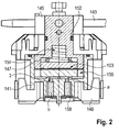
Fig. 2 shows a cross-sectional view of the leveling valve which is of more simplified manner as already described withFig. 1a and Fig. 1b including the noise reducing damping element according to a preferred embodiment, - here the same reference signs have been used to denote elements of similar kind and/or similar function; -
Fig. 3 with views (A) and (B) and with view (C) shows an enlarged representation of the leveling valve according toFig. 2 ; -
Fig. 4 shows an enlarged representation of the noise reducing damping element; -
Fig. 5 shows a block diagram of a vehicle having an air suspension system for use in a vehicle as well as the leveling valve according to a preferred embodiment of the invention - namely e. g. as shown inFig. 1 andFig. 2 . - A leveling
valve 101 in accordance with a preferred embodiment of the invention is depicted inFig. 1a and enlarged in a sectional view inFig. 1b - the simplified shown embodiment is depicted inFig. 2 . Thus, the further description is with regard toFig. 1a, Fig. 1b andFig. 2 in equal terms. The levelingvalve 101 comprises avalve arrangement 103 for directing air between (as shown inFig. 5 ) a plurality ofutilization elements 205a,b and either asource 207 of pressurized air or anexhaust port 3. Thevalve arrangement 103 is preferably a valve disc arrangement. It comprises afirst valve disc 107 and asecond valve disc 109. The first andsecond valve discs valve arrangement 103 comprise respective flow portions forming flow paths for guiding the air through the valve. The first andsecond valve discs first valve disc 107 is mounted to be stationary inside ahousing 140 of the levelingvalve 101. Thesecond valve disc 109 is mounted to be rotatable inside thehousing 140. Thehousing 140 of the levelingvalve 101 comprises abase body 141. Thefirst valve disc 107 is mounted non-rotatably inside thatbase body 141. Thehousing 140 further comprises arotatable housing part 145 which is fastened to thebase body 141 by way of ahousing lid 148 and extends into thebase body 141. Inside afirst air plenum 154 formed between therotatable housing part 145 and thebase body 141, a resilient means, for example in the form of aspring 147, is located and effective to push thesecond valve disc 109 towards thefirst valve disc 107 in order to establish a sealing, preferably air-tight relationship between thevalve discs valve arrangement 103 and the housing, in particular with respect to thebase body 141 of the housing 140 - this is also clearly visible inFig. 2 . - The
base body 141 of thehousing 140 comprises (as shown inFig. 5 ) afirst fluid channel 21 at the end of which there is located aconnector 142a for connecting the levelingvalve 101 and in particular thefirst fluid channel 21 to autilization element 205a of a vehicle (as shown inFig. 5 ). - Further, said
base body 141 comprises asecond fluid channel 22. At the end of thesecond fluid channel 22 there is located a connector 142b for connecting the levelingvalve 101 to asecond utilization element 205b.Utilization elements 205a,b may for example be pneumatic suspension bellows of a truck vehicle, wherein thefirst utilization element 205a might be right side suspension bellow of a vehicle whereas thesecond utilization element 205b might be the left side suspension bellow of the vehicle, or vice versa. - The
fluid channels first valve disc 107 of thevalve arrangement 103. - The rotating
portion 145 of thehousing 140 comprises an external mounting section which inFig. 1a receives alever 143 for operating thevalve 101. The lever comprises at its --inFig. 1a -- rightmost end portion a coupling means 150 engage a portion of the vehicle. Mechanical elements for translating a control motion from the vehicle to thevalve 101 may be rollers, steering rods, etc.. Upon actuation of thelever 143, therotatable housing portion 145 is rotated relative to thebase body 141 of thehousing 140. Thesecond valve disc 109 of thevalve arrangement 103 is mounted non-rotatably with respect to therotatable housing portion 145. Thus, upon actuation of thelever 143, thesecond valve disc 109 is rotated relative to thefirst valve disc 107 in this embodiment. - The
base body 141 and therotatable housing part 145, as well as therotatable housing part 145 and thehousing lid 148, are sealed against dirt ingress with one or more dirt seals 152. Saidfirst air plenum 154 is thus exposed to atmospheric pressure (as e.g. shown inFig. 1a ). The levelingvalve 101 may optionally comprise athrottle 115a or 115c.Fig. 1a exemplarily showsthrottle 115a which formed as a flow passage in the shape of a conical bore in thebase body 141, connecting the first and secondfluid channels second valve discs first valve disc 107. - The fluid flow into and out of the leveling
valve 101 are best seen fromFig. 1a ; this is why in regard to reference signs, explicit reference is made toFig. 1a and the air flow into and out of levelingvalve 101 is accomplished as will be apparent hereinafter. The levelingvalve 101 comprises in its base body 141 afluid supply port 1. Thefluid supply port 1 is in air-tight sealing contact with thefirst valve disc 107 and in fluid communication with afirst air passage 117 in thefirst valve disc 107. - The
fluid supply port 1 also comprises aconnector 142c similar toconnectors 142a,b (shown inFig. 5 ) also shown inFig. 1a , which lead to theutilization elements 205a,b.Connector 142c is adapted for connection to asource 207 of pressurized air. - Adjacent the
connector 142c, thefluid supply port 1 houses acheck valve 5 comprising alip seal 7, wherein thelip seal 7 is configured to allow fluid flow inwards, towards thevalve arrangement 103, and which is configured to prevent flow outwards, meaning from thevalve arrangement 103 towards the source ofpressurized air 207. - The
check valve 5 is mounted directly adjacent theconnector 142c and extends in a firstelongate section 9, as e.g. shown inFig. 1b . Thelip seal 7 abuts against awall 13 of thefluid supply port 1 in the firstelongate section 9. Additionally, thefluid supply port 1 comprises a secondelongate section 11 in which theconnector 142c is mounted. In between the first and secondelongate sections transition zone 10, which comprises a conically tapered section. Optionally, a sealingelement 12 may be arranged in between thecheck valve 5 and theconnector 142c. - Through
fluid supply port 1, pressurized air can be supplied through thefirst air passage 117 into a first flow portion 125 of the first valve disc 107 (Fig. 1 a) . Depending on the angle of rotation of thesecond valve disc 109 relative to thefirst valve disc 107, air will be transported in fluid communication through acrosslink portion 137 of thesecond valve disc 109 to second and third air passages 119, 121 in the first valve disc and from there to the first and secondfluid channels utilization elements 205a,b. In the other switching scenario, air is being transported through thefluid channels first valve disc 107 into thesecond valve disc 109, through a second flow portion 127 in thesecond valve disc 109 and from there to afourth air passage 123 in thefirst valve disc 107. Thefourth air passage 123 in thefirst valve disc 107 is fluid communication with asecond air plenum 156. - With continued reference to the reference signs mentioned with respect to
Fig. 1a and Fig. 1b further details of thecheck valve 5 are described. Thecheck valve 5 has aninlet side 4 and an outlet side 6. Aflow path 8 is defined in between theinlet side 4 and the outlet side 6. The flow path is delimited by abase body 15 of thecheck valve 5 and thelip seal 7. When mounted, as shown inFig. 1a ,wall 13 offluid supply port 1 also delimits theflow path 8. - The
lip seal 7 comprises a sealinglip 17 and anannular base 19. Theannular base 19 matingly engages arecess 24 formed in thebase body 15. The mating engagement prevents inadvertent removal of thelip seal 7 from thebase body 15 of thecheck valve 5. - Air streaming into the
check valve 5 from theinlet side 4 is led from within thecheck valve 5 to theperiphery 20 and onto thelip seal 7. After passing thelip seal 7, a recess provided in thebase body 15 of thecheck valve 5 guides theflow path 8 back inside, away from theperiphery 20 of thecheck valve 5. - On the outlet side 6 of the
check valve 5, a number ofpositioning elements 23 are provided in the form of radial and/or axial protrusions, which act as end stops for thecheck valve 5 inside thefluid supply port 1. Also, the end stop at least axially defines the mounted position of thecheck valve 5 inside thefluid supply port 1. Optionally, thepositioning elements 23 are formed such that they also position thecheck valve 5 radially in thefluid supply port 1 as a centering aid. - The
check valve 5 comprises on the inlet side 4 apositioning element 25, which is in the form of a ring. Thepositioning element 25 protrudes radially from thecheck valve 5 in order to determine the radial position of thecheck valve 5 inside thefluid supply port 1. - Optionally, the
base body 15 may comprise anend stop 27, which is adapted to be an abutment for the fluid conduit, which is introduced into thefluid supply port 1 and secured with theconnector 142c. Also, theend stop 27 prevents the fluid conduit from being introduced too far into the fluid supply port and ensures that the recess 29 for guiding the flow path outwards to theperiphery 20 remains sufficiently open. - As depicted in
Fig. 1b the sealinglip 17 oflip seal 7 is inclined at an angle α (not shown) towards the outlet side 6 of thecheck valve 5. If an air flow enterscheck valve 5 from the outlet side 6 towards the sealinglip 17, the sealing lip is pressed against the inclination angle α, which leads to the sealinglip 17 pressing tightly against the outer wall of thefluid supply port 1. Contrary thereto, when in normal operating condition, air streaming into thecheck valve 5 from theinlet side 4 will easily deform the sealinglip 17 to flex away from theouter wall 13 of thefluid supply port 1. - As can be seen from
Fig. 1a, Fig. 1b and in particular now turning toFig. 2 and also as shown further inFig. 2 , further anexhaust port 3 provided in thebase body 141 of levelingvalve 101 is in fluid communication with saidsecond air plenum 156. Theexhaust port 3 has an exhaust air channel a and is sealed against entry of air with anair flap 158 which opens if the pressure inside thesecond air plenum 156 is greater than the atmospheric pressure outside ofvalve 101. With reference toFig. 2 andFig. 3 theexhaust port 3 has an exhaust air channel a. - Further with reference to
Fig. 4 theexhaust port 3 comprises at least one air-permeable damping element b, which is at least partly positioned within the exhaust air channel a. The damping element b has the shape of a cylindrical ring having an axial through bore f, this is as best shown inFig. 4 a cylindrical ring damping element b'. - As shown in
Fig. 4 in the preferred embodiment, the damping element b, --here the cylindrical ring damping element b'-- has an outer diameter D in the range between D=15 - 19 [mm], preferably 17 [mm] and/or an inner diameter d in the range between d=5,5 - 9,5 [mm], preferably 7,5 [mm] and/or a length L, measured in the direction of the flow within the exhaust air channel, in the range between L= 8 - 12 [mm], preferably L=10[mm]. - In this regard --now turning to
Fig. 3 -- cross-sectionally shownexhaust part 3 with exhaust air channel a is depicted inFig. 3 (A) in a bottom view and a cross-sectional view C-C of the bottom view is depicted inFig. 3 (B) - thus showing the base body of levelingvalve 141 with theexhaust part 3 and the exhaust air channel a - an enlarged view thereof is given inFig. 3 (C) with detail U. - It is clear from this description that the damping element b shown as the cylindrical ring damping element b' in
Fig. 4 is adapted to replace into the exhaust air channel a as best shown inFig. 3 . AlsoFig. 3 (B) and Fig. 3 (C) thus technically show particularly adaptedspace 158c to place the mentionedair flap 158 therein. Thus, the damping element b -here the cylindrical ring damping element b'-- is positioned directly beneath theair flap 158 within the exhaust air channel a as already visible in the lower part ofFig. 3 in a cross-sectional view. So to say the side-by-side placement ofFig. 3 (C) and Fig. 4 depicts an exposition kind of view of the lower part ofFig. 2 with the air pearmable damping element b -here the cylindrical ring damping element b'-taken out of the exhaust air channel a. - As further can be seen from this structure depicted in
Fig. 3 (C) the exhaust air channel is configured within the space body of leveling valve as a kind of tubular recess such that the basically cylindrical ring damping element b' can be positioned therein. - In more detail the damping element b is positioned within a protruding, connected with the
housing 140, namely a tubular sleeve extension section connected with thebase body 141, of the leveling valve as shown inFig. 3 . In other words it is positioned adjacent to and upstream of anair flap 158 as shown inFig. 1a and a washer element (not shown, but near the air flap 158) within the exhaust air channel a. The damping element b is positioned around a central positioning element e extending through an axial through bore f of the damping element b and being positioned centrally within the exhaust air channel a. - Thus, thereby the damping element b -here the cylindrical ring damping element b'-- is positioned around a central positioning element e extending through an axial bore f of the damping element b and being positioned centrally within the exhaust air channel a, and wherein the damping element b -here the cylindrical ring damping element b'--is positioned within a tubular sleeve or tubular section of the housing of the leveling valve. The damping element has a density in the range of 0,19 +/- 0.1 (g/cm3) and/or an air permeability of or above 200 [L/min] and/or a diameter/length ratio in the range of 1.7.
-
Fig. 5 shows an exemplary use of thevalve 101 according to the preferred embodiment ofFigs. 1 to Fig. 4 . In particular,Fig. 5 schematically shows avehicle 300. Thevehicle 300 comprises anaxle 301 supporting a number oftyres 303. Thetyres 303 and theaxle 301 are linked through anair suspension system 200 to asuperstructure 305. - Said
air suspension system 200 comprises a plurality ofutilization elements 205a,b such as pneumatic suspension bellows. Theutilization elements 205a,b are functionally linked to theaxle 301 and/or optionally directly to a single-tyre support (not shown). - Said
utilization elements 205a,b are connected through afirst fluid channel 21 and asecond fluid channel 22 to thevalve disc arrangement 103 ofvalve 101. Upon rotation of a lever (not shown inFig. 5 ), such aslever 143 ofFig. 1 , thevalve 101 can be. Depending on the switching position, air is transported from the utilization elements through thevalve 101 to anexhaust port 3. - Alternatively, air can be supplied from a
source 207 of pressurized air throughfluid supply port 1 to thevalve 101 and from thereon to theutilization elements 205a,b. -
- 1
- fluid (air) supply port
- 3
- fluid (air) exhaust port
- a
- exhaust air channel
- b
- damping element
- b'
- cylindrical ring damping element
- e
- central positioning element
- f
- axial through bore of the damping element
- L
- length
- 4
- inlet side
- 5
- check valve
- 6
- outlet side
- 7
- lip seal
- 8
- flow path
- 9
- first elongate section
- 10
- transition section
- 11
- second elongate section
- 12
- sealing element
- 13
- outer wall
- 15
- base body
- 17
- sealing lip
- 19
- annular base
- 20
- outer periphery
- 21
- first fluid (air) channel
- 22
- second fluid (air) channel
- 23
- (second) positioning element
- 24
- recess
- 25
- (first) positioning element
- 27
- end stop
- 29
- (first) recess
- 31
- (second) recess
- 101
- leveling valve
- 103
- valve arrangement
- 107
- first valve disc
- 109
- second valve disc
- 115a,c
- throttle
- 117
- first air passage (for connection to source of pressurized air)
- 119
- second air passage (for connection to first utilization element)
- 121
- third air passage (for connection to second utilization element)
- 123
- fourth air passage (for connection to air exhaust)
- 125
- first flow portion (of first air passage)
- 127
- second flow portion (of fourth air passage)
- 137
- crosslink flow portion
- 140
- housing
- 141
- base body of leveling valve
- 141s
- tubular sleeve extension section as a protruding, connected with the
base body 141 - 142a,b,c
- connectors
- 143
- lever
- 145
- rotatable housing port
- 147
- spring
- 148
- housing lid
- 150
- coupling means
- 152
- dirt seal
- 154
- first air plenum
- 156
- second air plenum
- 158
- air flap
- 158c
- space
- 200
- Air suspension system
- 205a,b
- utilization elements, in particular in the form of suspension bellows
- 207
- source of pressurized air
- 300
- vehicle
- 301
- vehicle axle
- 303
- tyre
- 305
- superstructure
- α
- inclination angle
Claims (13)
- A leveling valve (101) for discharging and supplying air from and to a plurality of utilization elements (205a, b), in particular pneumatic suspension bellows, the leveling valve comprising:a valve arrangement (103) for directing air between a source (207) of pressurized air, an exhaust port (3) and said utilization elements,a supply port (1) in fluid communication with the valve arrangement (103) and the source (207) of pressurized air, andan exhaust port (3) having an exhaust air channel (a) for discharging exhaust air, wherein the exhaust port (3) comprises at least one air-permeable damping element (b), which is at least partly positioned within the exhaust air channel (a)characterized in that the damping element (b) has the shape of a ring.
- The leveling valve (101) of claim 1,
wherein the damping element (b) comprises or consists of a textile material, preferably felt, wool felt, plastic felt, nonwovens or textile mesh - The leveling valve (101) of claim 1 or 2,
wherein the damping element (b) has a density of 0.19 [g/cm3] +/- 0.1 [g/cm3]. - The leveling valve (101) of at least one of claims 1 to 3,
wherein the damping element (b) has an air permeability in the range between 190 - 210 [L/min], preferably 200 [L/min]. - The leveling valve (101) of at least one of claims 1 to 4,
wherein the damping element (b) has an oil absorption capability in the range between 360-420 %. - The leveling valve (101) according to at least one of the preceding claims,
wherein the damping element (b) is formed as a cylindrical ring damping element (b') having a axial through bore (f), wherein preferably the inner diameter (d) of the axial through bore (f) is in the range between 6 - 8 mm, preferably 7.5 mm. - The leveling valve (101) of claim 6,
wherein the damping element (b) has - an outer diameter (D) in the range between 15 - 19 [mm], preferably an outer diameter (D) of 17 [mm], and/or - an inner diameter (d) in the range between 5,5 - 9,5 [mm], preferably an inner diameter (d) of 7,5 [mm], and/or - a length (L), measured in the direction of the flow within the exhaust air channel (a), in the range between 8 - 12 [mm], preferably a length (L) of 10 [mm]. - The leveling valve (101) according to at least one of the preceding claims,
wherein the damping element (b) is positioned within a tubular recess within the housing (140), in particular base body (141), of the leveling valve (101). - The leveling valve (101) according to at least one of the preceding claims,
wherein the damping element (b) is positioned within a protruding, preferably tubular sleeve extension section (141s), connected with the housing (140), in particular base body (141), of the leveling valve (101). - The leveling valve (101) according to at least one of the preceding claims,
wherein the damping element (b) is positioned upstream of an air flap (158) and/or a washer element within the exhaust air channel (a). - The leveling valve (101) according to at least one of the preceding claims,
wherein the damping element (b) is positioned around a central positioning element (e) extending through an axial through bore (f) of the damping element (b) and being positioned centrally within the exhaust air channel (a), and
wherein the damping element (b) is positioned within a tubular sleeve section (141s) of the housing (140), in particular base body (141), of the leveling valve (101), and/or
wherein the damping element (b) has a density in the range of 0,19 +/- 0.1 (g/cm3) and/or
an air permeability of or above 200 [L/min] and/or
a diameter (D)/length (L) ratio in the range of 1,7. - An air suspension system (200) for use in a vehicle (300), comprising
a plurality of utilization elements (205a, b) a leveling valve (101) for discharging and supplying air from and to said utilization elements (205a, b), and a source (207) of pressurized air connected to a fluid supply port (1) of said leveling valve (101),
characterized in that said leveling valve (101) is a leveling valve (101) according to any one of claims 1 to 11. - Vehicle (300), in particular formed as a commercial vehicle, comprising
a plurality of tires (303) mounted on a vehicle axle (301), a superstructure (305), and an air suspension system (200) coupling the axle (301) to said superstructure (305),
characterized in that said air suspension system (200) is an air suspension system (200) according to claim 12.
Priority Applications (3)
| Application Number | Priority Date | Filing Date | Title |
|---|---|---|---|
| EP17000787.6A EP3401134B1 (en) | 2017-05-08 | 2017-05-08 | Leveling valve for discharging and supplying fluid |
| US15/972,279 US10696120B2 (en) | 2017-05-08 | 2018-05-07 | Leveling valve for discharging and supplying fluid |
| CN201810431251.3A CN108869793B (en) | 2017-05-08 | 2018-05-08 | Leveling valve for discharging and supplying fluid |
Applications Claiming Priority (1)
| Application Number | Priority Date | Filing Date | Title |
|---|---|---|---|
| EP17000787.6A EP3401134B1 (en) | 2017-05-08 | 2017-05-08 | Leveling valve for discharging and supplying fluid |
Publications (2)
| Publication Number | Publication Date |
|---|---|
| EP3401134A1 EP3401134A1 (en) | 2018-11-14 |
| EP3401134B1 true EP3401134B1 (en) | 2020-04-01 |
Family
ID=58698919
Family Applications (1)
| Application Number | Title | Priority Date | Filing Date |
|---|---|---|---|
| EP17000787.6A Active EP3401134B1 (en) | 2017-05-08 | 2017-05-08 | Leveling valve for discharging and supplying fluid |
Country Status (3)
| Country | Link |
|---|---|
| US (1) | US10696120B2 (en) |
| EP (1) | EP3401134B1 (en) |
| CN (1) | CN108869793B (en) |
Cited By (1)
| Publication number | Priority date | Publication date | Assignee | Title |
|---|---|---|---|---|
| EP4596269A1 (en) * | 2024-02-02 | 2025-08-06 | ZF CV Systems Europe BV | Cabin levelling valve and system, commercial vehicle, method of assembling a cabin levelling valve, and use of a cabin levelling valve |
Families Citing this family (4)
| Publication number | Priority date | Publication date | Assignee | Title |
|---|---|---|---|---|
| DE102019101791A1 (en) * | 2019-01-24 | 2020-07-30 | Rapa Automotive Gmbh & Co. Kg | Valve block with filling connection |
| EP3885618B1 (en) * | 2020-03-23 | 2023-12-27 | ZF CV Systems Europe BV | Pneumatic valve, cabin levelling system and vehicle |
| EP4194669B1 (en) * | 2021-12-10 | 2025-02-26 | ZF CV Systems Europe BV | Brake valve with silencer or spout connector |
| EP4596268A1 (en) | 2024-02-02 | 2025-08-06 | ZF CV Systems Europe BV | Cabin levelling valve and system, commercial vehicle, method of assembling a cabin levelling valve, and use of a cabin levelling valve |
Family Cites Families (20)
| Publication number | Priority date | Publication date | Assignee | Title |
|---|---|---|---|---|
| US3162433A (en) * | 1956-10-29 | 1964-12-22 | Borg Warner | Leveling valve mechanism |
| US2965373A (en) * | 1958-04-28 | 1960-12-20 | Thompson Ramo Wooldridge Inc | Leveling valve |
| GB860034A (en) * | 1958-07-18 | 1961-02-01 | New Prod Corp | Control valve for air suspension system |
| BE626818A (en) * | 1962-01-25 | 1900-01-01 | ||
| US4340353A (en) * | 1980-10-31 | 1982-07-20 | Discovision Associates | Hot sprue valve assembly for an injection molding machine |
| US4391579A (en) * | 1981-09-23 | 1983-07-05 | Discovision Associates | Hot sprue valve assembly for an injection molding machine |
| US4886092A (en) * | 1988-10-24 | 1989-12-12 | Ridewell Corporation | Leveling valve |
| DE4440232A1 (en) * | 1993-11-23 | 1995-05-24 | Barksdale Inc | Miniature rotary slider valve |
| AU7069900A (en) * | 1999-08-24 | 2001-03-19 | Holland Neway International, Inc. | Trailing arm suspension and height control valve therefor |
| CA2448577C (en) * | 2001-05-25 | 2008-05-06 | David J. Bolt | Trailing arm suspension and height control system with motorized valve therefor |
| US7204478B2 (en) * | 2002-08-07 | 2007-04-17 | Haldex Brake Corporation | Height control valve with universal mounting for a suspension system |
| US20040120619A1 (en) * | 2002-12-18 | 2004-06-24 | Dong-Yeh Chai | Independent rotational supportive pad with use of flat bearing ring plate for CRT/TFT-LCD/PDP television monitor, computer monitor, stereo speaker, laptop computers and dinner dishes |
| US7503902B2 (en) * | 2004-10-07 | 2009-03-17 | Fresenius Medical Care Holdings, Inc. | Blood flow reversal valves and related systems and methods |
| DE102006017890C5 (en) * | 2005-04-16 | 2015-11-19 | Haldex Brake Products Gmbh | Control valve for systems for raising and lowering a vehicle body |
| US7846369B2 (en) * | 2006-03-29 | 2010-12-07 | Akopyan Razmik L | Apparatus and method for molding polymer parts by displacement injection molding |
| US20080252025A1 (en) * | 2007-04-12 | 2008-10-16 | Plath Victor A | Electronic height control system for a vehicle with multiple input signals |
| DE102009007691B3 (en) | 2009-02-05 | 2010-08-05 | Knorr-Bremse Systeme für Nutzfahrzeuge GmbH | Level control valve with pressure-loaded valve disc |
| US9309979B2 (en) * | 2010-04-28 | 2016-04-12 | Larry Rayner Russell | Self piloted check valve |
| US8973922B2 (en) * | 2013-03-15 | 2015-03-10 | Haldex Brake Products Corporation | Air suspension height control valve with dual ride height positions |
| EP2806194B1 (en) | 2013-05-21 | 2018-01-03 | WABCO Europe BVBA | Leveling valve for discharging and supplying fluid |
-
2017
- 2017-05-08 EP EP17000787.6A patent/EP3401134B1/en active Active
-
2018
- 2018-05-07 US US15/972,279 patent/US10696120B2/en active Active
- 2018-05-08 CN CN201810431251.3A patent/CN108869793B/en active Active
Non-Patent Citations (1)
| Title |
|---|
| None * |
Cited By (1)
| Publication number | Priority date | Publication date | Assignee | Title |
|---|---|---|---|---|
| EP4596269A1 (en) * | 2024-02-02 | 2025-08-06 | ZF CV Systems Europe BV | Cabin levelling valve and system, commercial vehicle, method of assembling a cabin levelling valve, and use of a cabin levelling valve |
Also Published As
| Publication number | Publication date |
|---|---|
| EP3401134A1 (en) | 2018-11-14 |
| CN108869793B (en) | 2022-01-11 |
| US20180319240A1 (en) | 2018-11-08 |
| CN108869793A (en) | 2018-11-23 |
| US10696120B2 (en) | 2020-06-30 |
Similar Documents
| Publication | Publication Date | Title |
|---|---|---|
| US10696120B2 (en) | Leveling valve for discharging and supplying fluid | |
| US9616726B2 (en) | Leveling valve for discharging and supplying fluid | |
| EP3401133B1 (en) | Leveling valve | |
| US8292047B2 (en) | Hydraulic variable shock absorber with flow control valve | |
| JPS6229242B2 (en) | ||
| CA2584927A1 (en) | A body for actuating a standpipe of a replaceable filter element | |
| US20070023981A1 (en) | Gas spring system with centrally guided tubular rolling bellows | |
| CN101583808A (en) | Extensible end member for gas spring assembly | |
| CN216300699U (en) | an air suspension structure | |
| US4616811A (en) | Air suspension | |
| CN110608314B (en) | Air regulating valve, air regulating valve device, vehicle room suspension system and motor vehicle | |
| CN111971488A (en) | Damper bumper cover with labyrinth air passage | |
| EP1146247A2 (en) | Hydraulic damper for a vehicle | |
| US7014178B2 (en) | Hydraulically damping bush bearing | |
| EP1118793A2 (en) | Hydraulic damping valve | |
| US20110017317A1 (en) | Pneumatic tire valve device and the system and the process of setting the tire pressure | |
| KR20050003997A (en) | Automatic pumping, hydropneumatic strut unit | |
| EP3885618B1 (en) | Pneumatic valve, cabin levelling system and vehicle | |
| JPH0399968A (en) | Pressure medium reservoir tank | |
| US7422199B2 (en) | Self-pumping hydropneumatic suspension strut unit | |
| US6213475B1 (en) | Separating piston for a vibration damping system | |
| CN114517819B (en) | Single tube damper assembly and hydraulic rebound stop assembly therefor | |
| CN115556735A (en) | self-adjusting relay valve | |
| CN209813657U (en) | Air suspension system for vehicle | |
| CN223676876U (en) | A monotube magnetorheological vibration damper |
Legal Events
| Date | Code | Title | Description |
|---|---|---|---|
| PUAI | Public reference made under article 153(3) epc to a published international application that has entered the european phase |
Free format text: ORIGINAL CODE: 0009012 |
|
| STAA | Information on the status of an ep patent application or granted ep patent |
Free format text: STATUS: THE APPLICATION HAS BEEN PUBLISHED |
|
| AK | Designated contracting states |
Kind code of ref document: A1 Designated state(s): AL AT BE BG CH CY CZ DE DK EE ES FI FR GB GR HR HU IE IS IT LI LT LU LV MC MK MT NL NO PL PT RO RS SE SI SK SM TR |
|
| AX | Request for extension of the european patent |
Extension state: BA ME |
|
| STAA | Information on the status of an ep patent application or granted ep patent |
Free format text: STATUS: REQUEST FOR EXAMINATION WAS MADE |
|
| 17P | Request for examination filed |
Effective date: 20190514 |
|
| RBV | Designated contracting states (corrected) |
Designated state(s): AL AT BE BG CH CY CZ DE DK EE ES FI FR GB GR HR HU IE IS IT LI LT LU LV MC MK MT NL NO PL PT RO RS SE SI SK SM TR |
|
| GRAP | Despatch of communication of intention to grant a patent |
Free format text: ORIGINAL CODE: EPIDOSNIGR1 |
|
| STAA | Information on the status of an ep patent application or granted ep patent |
Free format text: STATUS: GRANT OF PATENT IS INTENDED |
|
| GRAJ | Information related to disapproval of communication of intention to grant by the applicant or resumption of examination proceedings by the epo deleted |
Free format text: ORIGINAL CODE: EPIDOSDIGR1 |
|
| STAA | Information on the status of an ep patent application or granted ep patent |
Free format text: STATUS: REQUEST FOR EXAMINATION WAS MADE |
|
| INTG | Intention to grant announced |
Effective date: 20191011 |
|
| GRAP | Despatch of communication of intention to grant a patent |
Free format text: ORIGINAL CODE: EPIDOSNIGR1 |
|
| STAA | Information on the status of an ep patent application or granted ep patent |
Free format text: STATUS: GRANT OF PATENT IS INTENDED |
|
| INTC | Intention to grant announced (deleted) | ||
| INTG | Intention to grant announced |
Effective date: 20191121 |
|
| GRAS | Grant fee paid |
Free format text: ORIGINAL CODE: EPIDOSNIGR3 |
|
| GRAA | (expected) grant |
Free format text: ORIGINAL CODE: 0009210 |
|
| STAA | Information on the status of an ep patent application or granted ep patent |
Free format text: STATUS: THE PATENT HAS BEEN GRANTED |
|
| AK | Designated contracting states |
Kind code of ref document: B1 Designated state(s): AL AT BE BG CH CY CZ DE DK EE ES FI FR GB GR HR HU IE IS IT LI LT LU LV MC MK MT NL NO PL PT RO RS SE SI SK SM TR |
|
| REG | Reference to a national code |
Ref country code: GB Ref legal event code: FG4D |
|
| REG | Reference to a national code |
Ref country code: CH Ref legal event code: EP Ref country code: AT Ref legal event code: REF Ref document number: 1250904 Country of ref document: AT Kind code of ref document: T Effective date: 20200415 |
|
| REG | Reference to a national code |
Ref country code: DE Ref legal event code: R096 Ref document number: 602017013779 Country of ref document: DE |
|
| REG | Reference to a national code |
Ref country code: IE Ref legal event code: FG4D |
|
| PG25 | Lapsed in a contracting state [announced via postgrant information from national office to epo] |
Ref country code: BG Free format text: LAPSE BECAUSE OF FAILURE TO SUBMIT A TRANSLATION OF THE DESCRIPTION OR TO PAY THE FEE WITHIN THE PRESCRIBED TIME-LIMIT Effective date: 20200701 |
|
| REG | Reference to a national code |
Ref country code: NL Ref legal event code: MP Effective date: 20200401 |
|
| REG | Reference to a national code |
Ref country code: LT Ref legal event code: MG4D |
|
| PG25 | Lapsed in a contracting state [announced via postgrant information from national office to epo] |
Ref country code: NL Free format text: LAPSE BECAUSE OF FAILURE TO SUBMIT A TRANSLATION OF THE DESCRIPTION OR TO PAY THE FEE WITHIN THE PRESCRIBED TIME-LIMIT Effective date: 20200401 Ref country code: SE Free format text: LAPSE BECAUSE OF FAILURE TO SUBMIT A TRANSLATION OF THE DESCRIPTION OR TO PAY THE FEE WITHIN THE PRESCRIBED TIME-LIMIT Effective date: 20200401 Ref country code: FI Free format text: LAPSE BECAUSE OF FAILURE TO SUBMIT A TRANSLATION OF THE DESCRIPTION OR TO PAY THE FEE WITHIN THE PRESCRIBED TIME-LIMIT Effective date: 20200401 Ref country code: CZ Free format text: LAPSE BECAUSE OF FAILURE TO SUBMIT A TRANSLATION OF THE DESCRIPTION OR TO PAY THE FEE WITHIN THE PRESCRIBED TIME-LIMIT Effective date: 20200401 Ref country code: NO Free format text: LAPSE BECAUSE OF FAILURE TO SUBMIT A TRANSLATION OF THE DESCRIPTION OR TO PAY THE FEE WITHIN THE PRESCRIBED TIME-LIMIT Effective date: 20200701 Ref country code: IS Free format text: LAPSE BECAUSE OF FAILURE TO SUBMIT A TRANSLATION OF THE DESCRIPTION OR TO PAY THE FEE WITHIN THE PRESCRIBED TIME-LIMIT Effective date: 20200801 Ref country code: PT Free format text: LAPSE BECAUSE OF FAILURE TO SUBMIT A TRANSLATION OF THE DESCRIPTION OR TO PAY THE FEE WITHIN THE PRESCRIBED TIME-LIMIT Effective date: 20200817 Ref country code: GR Free format text: LAPSE BECAUSE OF FAILURE TO SUBMIT A TRANSLATION OF THE DESCRIPTION OR TO PAY THE FEE WITHIN THE PRESCRIBED TIME-LIMIT Effective date: 20200702 Ref country code: LT Free format text: LAPSE BECAUSE OF FAILURE TO SUBMIT A TRANSLATION OF THE DESCRIPTION OR TO PAY THE FEE WITHIN THE PRESCRIBED TIME-LIMIT Effective date: 20200401 |
|
| REG | Reference to a national code |
Ref country code: AT Ref legal event code: MK05 Ref document number: 1250904 Country of ref document: AT Kind code of ref document: T Effective date: 20200401 |
|
| PG25 | Lapsed in a contracting state [announced via postgrant information from national office to epo] |
Ref country code: LV Free format text: LAPSE BECAUSE OF FAILURE TO SUBMIT A TRANSLATION OF THE DESCRIPTION OR TO PAY THE FEE WITHIN THE PRESCRIBED TIME-LIMIT Effective date: 20200401 Ref country code: RS Free format text: LAPSE BECAUSE OF FAILURE TO SUBMIT A TRANSLATION OF THE DESCRIPTION OR TO PAY THE FEE WITHIN THE PRESCRIBED TIME-LIMIT Effective date: 20200401 Ref country code: HR Free format text: LAPSE BECAUSE OF FAILURE TO SUBMIT A TRANSLATION OF THE DESCRIPTION OR TO PAY THE FEE WITHIN THE PRESCRIBED TIME-LIMIT Effective date: 20200401 |
|
| PG25 | Lapsed in a contracting state [announced via postgrant information from national office to epo] |
Ref country code: AL Free format text: LAPSE BECAUSE OF FAILURE TO SUBMIT A TRANSLATION OF THE DESCRIPTION OR TO PAY THE FEE WITHIN THE PRESCRIBED TIME-LIMIT Effective date: 20200401 |
|
| REG | Reference to a national code |
Ref country code: DE Ref legal event code: R097 Ref document number: 602017013779 Country of ref document: DE |
|
| PG25 | Lapsed in a contracting state [announced via postgrant information from national office to epo] |
Ref country code: IT Free format text: LAPSE BECAUSE OF FAILURE TO SUBMIT A TRANSLATION OF THE DESCRIPTION OR TO PAY THE FEE WITHIN THE PRESCRIBED TIME-LIMIT Effective date: 20200401 Ref country code: RO Free format text: LAPSE BECAUSE OF FAILURE TO SUBMIT A TRANSLATION OF THE DESCRIPTION OR TO PAY THE FEE WITHIN THE PRESCRIBED TIME-LIMIT Effective date: 20200401 Ref country code: EE Free format text: LAPSE BECAUSE OF FAILURE TO SUBMIT A TRANSLATION OF THE DESCRIPTION OR TO PAY THE FEE WITHIN THE PRESCRIBED TIME-LIMIT Effective date: 20200401 Ref country code: SM Free format text: LAPSE BECAUSE OF FAILURE TO SUBMIT A TRANSLATION OF THE DESCRIPTION OR TO PAY THE FEE WITHIN THE PRESCRIBED TIME-LIMIT Effective date: 20200401 Ref country code: AT Free format text: LAPSE BECAUSE OF FAILURE TO SUBMIT A TRANSLATION OF THE DESCRIPTION OR TO PAY THE FEE WITHIN THE PRESCRIBED TIME-LIMIT Effective date: 20200401 Ref country code: LI Free format text: LAPSE BECAUSE OF NON-PAYMENT OF DUE FEES Effective date: 20200531 Ref country code: DK Free format text: LAPSE BECAUSE OF FAILURE TO SUBMIT A TRANSLATION OF THE DESCRIPTION OR TO PAY THE FEE WITHIN THE PRESCRIBED TIME-LIMIT Effective date: 20200401 Ref country code: ES Free format text: LAPSE BECAUSE OF FAILURE TO SUBMIT A TRANSLATION OF THE DESCRIPTION OR TO PAY THE FEE WITHIN THE PRESCRIBED TIME-LIMIT Effective date: 20200401 Ref country code: MC Free format text: LAPSE BECAUSE OF FAILURE TO SUBMIT A TRANSLATION OF THE DESCRIPTION OR TO PAY THE FEE WITHIN THE PRESCRIBED TIME-LIMIT Effective date: 20200401 Ref country code: CH Free format text: LAPSE BECAUSE OF NON-PAYMENT OF DUE FEES Effective date: 20200531 |
|
| PLBE | No opposition filed within time limit |
Free format text: ORIGINAL CODE: 0009261 |
|
| STAA | Information on the status of an ep patent application or granted ep patent |
Free format text: STATUS: NO OPPOSITION FILED WITHIN TIME LIMIT |
|
| PG25 | Lapsed in a contracting state [announced via postgrant information from national office to epo] |
Ref country code: SK Free format text: LAPSE BECAUSE OF FAILURE TO SUBMIT A TRANSLATION OF THE DESCRIPTION OR TO PAY THE FEE WITHIN THE PRESCRIBED TIME-LIMIT Effective date: 20200401 Ref country code: PL Free format text: LAPSE BECAUSE OF FAILURE TO SUBMIT A TRANSLATION OF THE DESCRIPTION OR TO PAY THE FEE WITHIN THE PRESCRIBED TIME-LIMIT Effective date: 20200401 |
|
| 26N | No opposition filed |
Effective date: 20210112 |
|
| REG | Reference to a national code |
Ref country code: BE Ref legal event code: MM Effective date: 20200531 |
|
| PG25 | Lapsed in a contracting state [announced via postgrant information from national office to epo] |
Ref country code: LU Free format text: LAPSE BECAUSE OF NON-PAYMENT OF DUE FEES Effective date: 20200508 |
|
| PG25 | Lapsed in a contracting state [announced via postgrant information from national office to epo] |
Ref country code: IE Free format text: LAPSE BECAUSE OF NON-PAYMENT OF DUE FEES Effective date: 20200508 |
|
| PG25 | Lapsed in a contracting state [announced via postgrant information from national office to epo] |
Ref country code: BE Free format text: LAPSE BECAUSE OF NON-PAYMENT OF DUE FEES Effective date: 20200531 Ref country code: SI Free format text: LAPSE BECAUSE OF FAILURE TO SUBMIT A TRANSLATION OF THE DESCRIPTION OR TO PAY THE FEE WITHIN THE PRESCRIBED TIME-LIMIT Effective date: 20200401 |
|
| REG | Reference to a national code |
Ref country code: DE Ref legal event code: R081 Ref document number: 602017013779 Country of ref document: DE Owner name: ZF CV SYSTEMS EUROPE BV, BE Free format text: FORMER OWNER: WABCO EUROPE BVBA, BRUESSEL, BE |
|
| PG25 | Lapsed in a contracting state [announced via postgrant information from national office to epo] |
Ref country code: TR Free format text: LAPSE BECAUSE OF FAILURE TO SUBMIT A TRANSLATION OF THE DESCRIPTION OR TO PAY THE FEE WITHIN THE PRESCRIBED TIME-LIMIT Effective date: 20200401 Ref country code: MT Free format text: LAPSE BECAUSE OF FAILURE TO SUBMIT A TRANSLATION OF THE DESCRIPTION OR TO PAY THE FEE WITHIN THE PRESCRIBED TIME-LIMIT Effective date: 20200401 Ref country code: CY Free format text: LAPSE BECAUSE OF FAILURE TO SUBMIT A TRANSLATION OF THE DESCRIPTION OR TO PAY THE FEE WITHIN THE PRESCRIBED TIME-LIMIT Effective date: 20200401 |
|
| PG25 | Lapsed in a contracting state [announced via postgrant information from national office to epo] |
Ref country code: MK Free format text: LAPSE BECAUSE OF FAILURE TO SUBMIT A TRANSLATION OF THE DESCRIPTION OR TO PAY THE FEE WITHIN THE PRESCRIBED TIME-LIMIT Effective date: 20200401 |
|
| P01 | Opt-out of the competence of the unified patent court (upc) registered |
Effective date: 20230528 |
|
| PGFP | Annual fee paid to national office [announced via postgrant information from national office to epo] |
Ref country code: GB Payment date: 20240314 Year of fee payment: 8 |
|
| PGFP | Annual fee paid to national office [announced via postgrant information from national office to epo] |
Ref country code: FR Payment date: 20240308 Year of fee payment: 8 |
|
| PGFP | Annual fee paid to national office [announced via postgrant information from national office to epo] |
Ref country code: DE Payment date: 20250311 Year of fee payment: 9 |
|
| GBPC | Gb: european patent ceased through non-payment of renewal fee |
Effective date: 20250508 |
|
| PG25 | Lapsed in a contracting state [announced via postgrant information from national office to epo] |
Ref country code: GB Free format text: LAPSE BECAUSE OF NON-PAYMENT OF DUE FEES Effective date: 20250508 |
|
| PG25 | Lapsed in a contracting state [announced via postgrant information from national office to epo] |
Ref country code: FR Free format text: LAPSE BECAUSE OF NON-PAYMENT OF DUE FEES Effective date: 20250531 |