EP3400869B1 - Magnetic particle imaging (mpi) device - Google Patents
Magnetic particle imaging (mpi) device Download PDFInfo
- Publication number
- EP3400869B1 EP3400869B1 EP18171932.9A EP18171932A EP3400869B1 EP 3400869 B1 EP3400869 B1 EP 3400869B1 EP 18171932 A EP18171932 A EP 18171932A EP 3400869 B1 EP3400869 B1 EP 3400869B1
- Authority
- EP
- European Patent Office
- Prior art keywords
- magnetic
- electromagnets
- electromagnet
- permanent magnet
- network
- Prior art date
- Legal status (The legal status is an assumption and is not a legal conclusion. Google has not performed a legal analysis and makes no representation as to the accuracy of the status listed.)
- Active
Links
Images


Classifications
-
- A—HUMAN NECESSITIES
- A61—MEDICAL OR VETERINARY SCIENCE; HYGIENE
- A61B—DIAGNOSIS; SURGERY; IDENTIFICATION
- A61B5/00—Measuring for diagnostic purposes; Identification of persons
- A61B5/05—Detecting, measuring or recording for diagnosis by means of electric currents or magnetic fields; Measuring using microwaves or radio waves
- A61B5/0515—Magnetic particle imaging
-
- G—PHYSICS
- G01—MEASURING; TESTING
- G01R—MEASURING ELECTRIC VARIABLES; MEASURING MAGNETIC VARIABLES
- G01R33/00—Arrangements or instruments for measuring magnetic variables
- G01R33/12—Measuring magnetic properties of articles or specimens of solids or fluids
- G01R33/1276—Measuring magnetic properties of articles or specimens of solids or fluids of magnetic particles, e.g. imaging of magnetic nanoparticles
-
- A—HUMAN NECESSITIES
- A61—MEDICAL OR VETERINARY SCIENCE; HYGIENE
- A61B—DIAGNOSIS; SURGERY; IDENTIFICATION
- A61B2562/00—Details of sensors; Constructional details of sensor housings or probes; Accessories for sensors
- A61B2562/02—Details of sensors specially adapted for in-vivo measurements
- A61B2562/0223—Magnetic field sensors
-
- A—HUMAN NECESSITIES
- A61—MEDICAL OR VETERINARY SCIENCE; HYGIENE
- A61B—DIAGNOSIS; SURGERY; IDENTIFICATION
- A61B2562/00—Details of sensors; Constructional details of sensor housings or probes; Accessories for sensors
- A61B2562/04—Arrangements of multiple sensors of the same type
-
- A—HUMAN NECESSITIES
- A61—MEDICAL OR VETERINARY SCIENCE; HYGIENE
- A61B—DIAGNOSIS; SURGERY; IDENTIFICATION
- A61B5/00—Measuring for diagnostic purposes; Identification of persons
- A61B5/72—Signal processing specially adapted for physiological signals or for diagnostic purposes
- A61B5/7225—Details of analogue processing, e.g. isolation amplifier, gain or sensitivity adjustment, filtering, baseline or drift compensation
Definitions
- the present invention relates to an MPI (Magnetic Particle Imaging) device.
- Magnetic particle imaging technology was first presented in 2005 by authors Gleich and Weizenecker ( B. Gleich, and R. Weizenecker) in "Tomographic imaging using the nonlinear response of magnetic particles", Nature, 435 (2005), pp. 1214-1217 ).
- the MPI imaging device further comprises a second magnetic excitation system adapted to generate a pulsating high-frequency magnetic field within this spot so as to excite iron oxide microparticles injected into the circulatory system of a patient having a portion of his or her body positioned in said three-dimensional measuring space.
- MPI analysis also employs an antenna system adapted to detect the response of the iron oxide microparticles.
- the proposed experimental imaging devices provide a measuring space that is entirely surrounded by magnetic deflection systems that make access to the patient impossible when he or she is positioned, totally or partially, within the measuring space.
- the present invention is intended to resolve the aforementioned technical problem.
- Magnetic Particle Imaging device comprising a first magnetic control system configured to generate a magnetic field inside a three-dimensional measuring space and to obtain, within this three-dimensional space, the movement in three directions X, Y, and Z of a spot wherein the field has a value lower than a threshold, said Magnetic Particle Imaging device further comprising a second magnetic excitation system configured to generate a pulsating magnetic field within said spot so as to excite iron oxide microparticles injected into the circulatory system of a patient having a portion of his or her body positioned in said three-dimensional measuring space, said magnetic control system comprises: a first bottom parallelepipedal permanent magnet; a second top parallelepipedal permanent magnet spaced apart from the first magnet in the vertical direction Z, the first permanent magnet and the second permanent magnet having mutually facing poles, coaxial magnetic axes, and being arranged on opposite sides of the three-dimensional measuring space; a first pair of first and second electromagnets arranged respectively
- FIG. 1 a device for MPI imaging (Magnetic Particle Imaging) is indicated by reference numeral 1.
- the device 1 comprises a first magnetic control system 3 configured to generate a magnetic field in a three-dimensional measuring space 4 and obtain, within this three-dimensional space 4, the movement in three directions X, Y and Z of a spot 5 within which the field has a value considerably lower than a threshold.
- the spot 5 can have an approximately spherical shape and a diameter of 1 mm or lower.
- the three-dimensional space 4 can be approximately cubic with sides 0.8-1 metre long.
- the device 1 further comprises a second magnetic excitation system 7 adapted to generate a pulsating magnetic field within the spot 5 so as to excite iron oxide microparticles injected into the circulatory system of a patient (not shown for simplicity) having a portion of his or her body positioned in the three-dimensional measuring space 4.
- a second magnetic excitation system 7 adapted to generate a pulsating magnetic field within the spot 5 so as to excite iron oxide microparticles injected into the circulatory system of a patient (not shown for simplicity) having a portion of his or her body positioned in the three-dimensional measuring space 4.
- the first magnetic control system 3 comprises a first bottom parallelepipedal permanent magnet 10 (its shape is cubic in the example), and a second top parallelepipedal permanent magnet 11 (its shape is cubic in the example) vertically spaced apart from the first magnet 10 in respect to the vertical direction Z.
- the spacing between the two magnets 10 and 11 can be in the order of approximately 1 metre.
- the first permanent magnet 10 and the second permanent magnet 11 have mutually facing poles of the same polarity, coaxial magnetic axes, and are arranged on opposite sides of the three-dimensional measuring space 4.
- the first magnetic control system 1 further comprises a first pair of first and second electromagnets 13a and 13b with axes parallel to the axes of the permanent magnets 10 and 11 in the direction Z, arranged respectively facing a first and a second side face 15a and 15b of the first bottom permanent magnet 10; the first and the second side faces 15a and 15b are arranged on opposite sides of the first parallelepipedal permanent magnet 10.
- the first pair of electromagnets 13a and 13b is adapted to generate, when powered, a magnetic field that combines with the magnetic field generated by the permanent magnets 10 and 11 and modifies the spatial arrangement of the lines of force of the field along a first horizontal direction X.
- the first magnetic control system 1 comprises a second pair of third and fourth electromagnets 13c and 13d with axes parallel to the axes of the permanent magnets 10 and 11 in the direction Z, arranged respectively facing a third and a fourth side face 15c and 15d of the first bottom permanent magnet 10; the third and the fourth side faces 15c and 15d are arranged on opposite sides of the first parallelepipedal permanent magnet 10.
- the second pair of electromagnets 13c and 13d is adapted to generate, when powered, a magnetic field that combines with the magnetic field generated by the permanent magnets 10 and 11 and modifies the spatial arrangement of the lines of force of the field along a second horizontal direction Y.
- the first parallelepipedal permanent magnet 10 has a fifth top face 15e facing the three-dimensional measuring space 4 and a sixth bottom face (not visible in Figure 1 ) facing a base portion of the device 1.
- the magnetic control system 1 comprises a fifth electromagnet 25e with its axis coaxial with the axes of the first and the second permanent magnets 10 and 11; the fifth electromagnet 25e is adapted to generate, when powered, a magnetic field that combines with the magnetic field generated by the permanent magnets 10 and 11 and modifies the spatial arrangement of the lines of force of the field along the vertical direction Z.
- the first and the second permanent magnets 10 and 11 comprise a plurality of magnetic modules 20 arranged alongside one another so as to produce a cubic structure housed in a casing 22 ( Figure 3 ) made of non-magnetic material configured to withstand the repulsive forces generated by the magnetic modules 20 arranged with the corresponding poles facing one another.
- Magnetic modules 20 made of neodymium-iron-boron (NdFeB) can be expediently used, the which, as is known, represent one of the best magnetic materials currently used in the industry.
- the casing 22 can be expediently made of reinforced fibreglass, Kevlar, carbon fibre or a high-resistance plastic material. It is opportune to avoid the use of any metal material (for example, metal screws).
- the first, second, third and fourth electromagnets 13a, 13b, 13c and 13d are devoid of a metal core and each comprise a coil with an insulated conductor wound about a hollow central portion inside which, in use, a cooling liquid circulates (this aspect will be described further on).
- the insulated conductor is expediently formed by a strand of enameled copper wires (litz wire) which is used in order to reduce the "skin effect", reducing the resistance of the AC current circulating in the coil.
- litz wire enameled copper wires
- the magnetic excitation system 7 comprises a plurality of electromagnets, the coils of which develop in planes perpendicular to the direction Z between the fifth face 15e of the first permanent magnet 10 and a bottom side of the three-dimensional measuring space 4.
- the magnetic excitation system 7 comprises a layered structure comprising:
- the first and the second electromagnets 23a and 23b are shaped in plan view like a rectangular frame with rounded corners and arranged with their longer sides parallel to one another
- the third and the fourth electromagnets 24c and 24d are shaped in plan view like a rectangular frame with rounded corners and arranged with their longer sides parallel to one another and perpendicular to the longer sides of the first and the second electromagnets 23a and 23b
- the fifth electromagnet 25e is rectangular in plan view, in particular square, and is arranged with a first pair of sides parallel to the longer sides of the first and the second electromagnets 23a and 23b and with a second pair of sides parallel to the longer sides of the third and the fourth electromagnets 24c and 24d.
- the third layer 25 is set close to and facing the three-dimensional measuring space 4
- the first layer 23 is set close to and facing the fifth face 15e of the bottom permanent magnet
- the second layer 24 is interposed between the first layer 23 and the third layer 25.
- the particular embodiment described above enables creating a measuring space 4 that is laterally open 360 degrees (the measuring space 4 is only delimited by the magnet 11 above and delimited below by the magnet 10 and by the coils belonging to the second magnetic excitation system 7 on top of the bottom magnet 10). Medical personnel can thus work unhindered on a patient with a portion of his or her body positioned in the measuring space.
- Figures 2 and 3 show a supporting and containing structure 30 for supporting the first magnetic control system 3 and the magnetic excitation system 7 that is made entirely of non-magnetic material (for example, in a high-resistance plastic material, generically known as "engineering plastics").
- the supporting structure 30 is formed by a substantially C-shaped portion comprising a vertical upright 32, a top transverse arm 33 adapted to support the second, top, permanent magnet 11, and a bottom structure 34 adapted to support the first bottom permanent magnet 10 and all the electromagnets that belong to the first magnetic control system 3 and to the magnetic excitation system 7.
- the bottom structure 34 supports a fluid-tight container 36 made of non-magnetic material that defines an inner chamber (not shown), which houses the first bottom permanent magnet 10 and all the electromagnets that belong to the first magnetic control system 3 and to the magnetic excitation system 7.
- a cooling system (of known type and not shown) is also provided, this being adapted to enable a flow of insulating cooling fluid (for example, transformer oil) between a supply inlet of the fluid-tight container 36 and a discharge outlet of the fluid-tight container 36. In this way, the cooling fluid can flow around the electromagnets and circulate through the portions of the electromagnets devoid of a metal core.
- Figure 6 shows a simplified wiring diagram of the low-frequency power-supply system 40 for powering the first magnetic control system 3, comprising:
- the first and the second power generators 41 and 43 receive as input the same excitation signal, but with opposite phases
- the third and the fourth power generators 45 and 47 receive as input the same excitation signal, but with opposite phases.
- the capacitors 42, 44, 46, 48 and 50 are expediently carried by the bottom structure 34 and are arranged beneath the fluid-tight container 36.
- a high-frequency power supply system 70 is provided for the magnetic excitation system 7 comprising:
- the first and the second power generators 51 and 53 receive as input the same excitation signal, but with opposite phases, and the third and the fourth power generators 55 and 57 receive as input the same excitation signal, but with opposite phases.
- the capacitors 52, 55, 56, 58 and 59 are expediently carried by the bottom structure 34 and are arranged beneath the fluid-tight container 36.
- Each LC network is provided with a frequency-control system adapted to supply it, by means of the respective power generator 41, 43, 45, 47, 49 and 51, 53, 55, 57, 59, with an AC signal having a frequency close to the resonant frequency of the LC network:
- the frequency-control system is schematically shown in Figure 5 and comprises:
- Figure 4 shows a system for controlling the current within each LC network, this current-control system implementing a control loop external to the control loop provided by the frequency-control system that drives the frequency of a sinusoidal waveform generator that determines the frequency of the sinusoid that powers each LC network.
- the current-control system comprises:
Landscapes
- Health & Medical Sciences (AREA)
- Life Sciences & Earth Sciences (AREA)
- Physics & Mathematics (AREA)
- Engineering & Computer Science (AREA)
- Nuclear Medicine, Radiotherapy & Molecular Imaging (AREA)
- Biophysics (AREA)
- Medical Informatics (AREA)
- Condensed Matter Physics & Semiconductors (AREA)
- Radiology & Medical Imaging (AREA)
- Nanotechnology (AREA)
- Chemical & Material Sciences (AREA)
- Pathology (AREA)
- Biomedical Technology (AREA)
- Heart & Thoracic Surgery (AREA)
- General Physics & Mathematics (AREA)
- Molecular Biology (AREA)
- Surgery (AREA)
- Animal Behavior & Ethology (AREA)
- General Health & Medical Sciences (AREA)
- Public Health (AREA)
- Veterinary Medicine (AREA)
- Magnetic Resonance Imaging Apparatus (AREA)
- Investigating Or Analyzing Materials By The Use Of Magnetic Means (AREA)
Description
- The present invention relates to an MPI (Magnetic Particle Imaging) device.
- Magnetic particle imaging technology was first presented in 2005 by authors Gleich and Weizenecker (B. Gleich, and R. Weizenecker) in "Tomographic imaging using the nonlinear response of magnetic particles", Nature, 435 (2005), pp. 1214-1217).
- Some prototypes of imaging devices have now been developed of the type comprising a first magnetic control system configured to generate a low-frequency magnetic field in a three-dimensional measuring space and obtaining, within said three-dimensional space, the movement along three axes X, Y and Z of a spot in which the field has a value lower than a threshold value. The MPI imaging device further comprises a second magnetic excitation system adapted to generate a pulsating high-frequency magnetic field within this spot so as to excite iron oxide microparticles injected into the circulatory system of a patient having a portion of his or her body positioned in said three-dimensional measuring space. MPI analysis also employs an antenna system adapted to detect the response of the iron oxide microparticles.
- By analysing the signal detected by the antenna it is actually possible to map a three-dimensional image of portions of the human body permeated by blood vessels, as the portion of the body where blood vessels are present corresponds to the portion of the body where the iron oxide microparticles oscillate due to the high-frequency magnetic excitation. Iron oxide microparticles outside the spot cannot oscillate at high frequency as they are polarized by the strong magnetic field produced by the magnetic control system.
- Until now, the proposed experimental imaging devices provide a measuring space that is entirely surrounded by magnetic deflection systems that make access to the patient impossible when he or she is positioned, totally or partially, within the measuring space.
- Document US20157008910 discloses a Magnetic Particle Imaging (MPI) device.
- The present invention is intended to resolve the aforementioned technical problem.
- This technical problem is overcome by the present invention in so far as it relates to a Magnetic Particle Imaging device comprising a first magnetic control system configured to generate a magnetic field inside a three-dimensional measuring space and to obtain, within this three-dimensional space, the movement in three directions X, Y, and Z of a spot wherein the field has a value lower than a threshold, said Magnetic Particle Imaging device further comprising a second magnetic excitation system configured to generate a pulsating magnetic field within said spot so as to excite iron oxide microparticles injected into the circulatory system of a patient having a portion of his or her body positioned in said three-dimensional measuring space, said magnetic control system comprises: a first bottom parallelepipedal permanent magnet; a second top parallelepipedal permanent magnet spaced apart from the first magnet in the vertical direction Z, the first permanent magnet and the second permanent magnet having mutually facing poles, coaxial magnetic axes, and being arranged on opposite sides of the three-dimensional measuring space; a first pair of first and second electromagnets arranged respectively facing a first and a second side face of the first bottom permanent magnet, the first and the second side faces being arranged on opposite sides of the first parallelepipedal permanent magnet, said first pair of electromagnets being configured to generate, when powered, a magnetic field that combines with the magnetic field generated by the permanent magnets and modifies the spatial arrangement of the lines of force of the field along a first horizontal direction X; and a second pair of third and fourth electromagnets arranged respectively facing a third and a fourth face of the first, bottom, permanent magnet, the third and the fourth faces being arranged on opposite sides of the first, parallelepipedal, permanent magnet, said second pair of electromagnets being configured to generate, when powered, a magnetic field that combines with the magnetic field generated by the permanent magnets and modifies the spatial arrangement of the lines of force of the field in a second horizontal direction Y; said first, parallelepipedal, permanent magnet having a fifth, top, face facing the three-dimensional measuring space and a sixth, bottom, face facing a base portion of the device; said magnetic control system further comprising a fifth electromagnet with its axis coaxial with the axes of the first and the second permanent magnets, said fifth electromagnet being adapted to generate, when powered, a magnetic field that combines with the magnetic field generated by the permanent magnets and modifies the spatial arrangement of the lines of force of the field along the vertical direction Z.
- The invention will now be described with reference to the accompanying drawings, which show a preferred non-limitative embodiment, in which:
-
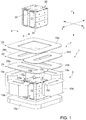
Figure 1 shows an exploded, perspective view of a device for MPI imaging embodied according to the teachings of the present invention; -
Figure 2 shows a side view of a device for MPI imaging embodied according to the teachings of the present invention; -
Figure 3 shows a perspective view of a device for MPI imaging embodied according to the teachings of the present invention; -
Figures 4 and 5 show control devices of the device according to the present invention; and -
Figure 6 shows a schematic circuit diagram of the magnetic part of the device according to the present invention. - In
Figure 1 , a device for MPI imaging (Magnetic Particle Imaging) is indicated byreference numeral 1. - The
device 1 comprises a firstmagnetic control system 3 configured to generate a magnetic field in a three-dimensional measuring space 4 and obtain, within this three-dimensional space 4, the movement in three directions X, Y and Z of aspot 5 within which the field has a value considerably lower than a threshold. Typically, thespot 5 can have an approximately spherical shape and a diameter of 1 mm or lower. The three-dimensional space 4 can be approximately cubic with sides 0.8-1 metre long. - The
device 1 further comprises a second magnetic excitation system 7 adapted to generate a pulsating magnetic field within thespot 5 so as to excite iron oxide microparticles injected into the circulatory system of a patient (not shown for simplicity) having a portion of his or her body positioned in the three-dimensional measuring space 4. - According to the present invention, the first
magnetic control system 3 comprises a first bottom parallelepipedal permanent magnet 10 (its shape is cubic in the example), and a second top parallelepipedal permanent magnet 11 (its shape is cubic in the example) vertically spaced apart from thefirst magnet 10 in respect to the vertical direction Z. The spacing between the twomagnets permanent magnet 10 and the secondpermanent magnet 11 have mutually facing poles of the same polarity, coaxial magnetic axes, and are arranged on opposite sides of the three-dimensional measuring space 4. - The first
magnetic control system 1 further comprises a first pair of first andsecond electromagnets permanent magnets second side face permanent magnet 10; the first and the second side faces 15a and 15b are arranged on opposite sides of the first parallelepipedalpermanent magnet 10. The first pair ofelectromagnets permanent magnets - The first
magnetic control system 1 comprises a second pair of third andfourth electromagnets permanent magnets fourth side face permanent magnet 10; the third and the fourth side faces 15c and 15d are arranged on opposite sides of the first parallelepipedalpermanent magnet 10. The second pair ofelectromagnets permanent magnets - The first parallelepipedal
permanent magnet 10 has a fifthtop face 15e facing the three-dimensional measuring space 4 and a sixth bottom face (not visible inFigure 1 ) facing a base portion of thedevice 1. - Finally, the
magnetic control system 1 comprises afifth electromagnet 25e with its axis coaxial with the axes of the first and the secondpermanent magnets fifth electromagnet 25e is adapted to generate, when powered, a magnetic field that combines with the magnetic field generated by thepermanent magnets - The first and the second
permanent magnets magnetic modules 20 arranged alongside one another so as to produce a cubic structure housed in a casing 22 (Figure 3 ) made of non-magnetic material configured to withstand the repulsive forces generated by themagnetic modules 20 arranged with the corresponding poles facing one another.Magnetic modules 20 made of neodymium-iron-boron (NdFeB) can be expediently used, the which, as is known, represent one of the best magnetic materials currently used in the industry. - The
casing 22 can be expediently made of reinforced fibreglass, Kevlar, carbon fibre or a high-resistance plastic material. It is opportune to avoid the use of any metal material (for example, metal screws). - The first, second, third and
fourth electromagnets - The insulated conductor is expediently formed by a strand of enameled copper wires (litz wire) which is used in order to reduce the "skin effect", reducing the resistance of the AC current circulating in the coil.
- The magnetic excitation system 7 comprises a plurality of electromagnets, the coils of which develop in planes perpendicular to the direction Z between the
fifth face 15e of the firstpermanent magnet 10 and a bottom side of the three-dimensional measuring space 4. - In greater detail, the magnetic excitation system 7 comprises a layered structure comprising:
- a
first bottom layer 23, in which there is a first and asecond excitation electromagnet second electromagnets - a second
intermediate layer 24, in which there is a third and afourth excitation electromagnet fourth electromagnets - a
third top layer 25, in which there is afifth excitation electromagnet 25e having its axis parallel to the direction Z; the field formed by thefifth electromagnet 25e is adapted to create lines of force that move in the third direction Z. - The first and the
second electromagnets fourth electromagnets second electromagnets fifth electromagnet 25e is rectangular in plan view, in particular square, and is arranged with a first pair of sides parallel to the longer sides of the first and thesecond electromagnets fourth electromagnets - The
third layer 25 is set close to and facing the three-dimensional measuring space 4, thefirst layer 23 is set close to and facing thefifth face 15e of the bottom permanent magnet, and thesecond layer 24 is interposed between thefirst layer 23 and thethird layer 25. - The particular embodiment described above enables creating a
measuring space 4 that is laterally open 360 degrees (themeasuring space 4 is only delimited by themagnet 11 above and delimited below by themagnet 10 and by the coils belonging to the second magnetic excitation system 7 on top of the bottom magnet 10). Medical personnel can thus work unhindered on a patient with a portion of his or her body positioned in the measuring space. - This arrangement constitutes an evident advantage with respect to known devices, in which the measuring space is totally surrounded by magnetic deflection systems that make access to the patient impossible when he or she is positioned, totally or partially, in the measuring space.
-
Figures 2 and 3 show a supporting and containingstructure 30 for supporting the firstmagnetic control system 3 and the magnetic excitation system 7 that is made entirely of non-magnetic material (for example, in a high-resistance plastic material, generically known as "engineering plastics"). The supportingstructure 30 is formed by a substantially C-shaped portion comprising a vertical upright 32, a toptransverse arm 33 adapted to support the second, top,permanent magnet 11, and abottom structure 34 adapted to support the first bottompermanent magnet 10 and all the electromagnets that belong to the firstmagnetic control system 3 and to the magnetic excitation system 7. - The
bottom structure 34 supports a fluid-tight container 36 made of non-magnetic material that defines an inner chamber (not shown), which houses the first bottompermanent magnet 10 and all the electromagnets that belong to the firstmagnetic control system 3 and to the magnetic excitation system 7. A cooling system (of known type and not shown) is also provided, this being adapted to enable a flow of insulating cooling fluid (for example, transformer oil) between a supply inlet of the fluid-tight container 36 and a discharge outlet of the fluid-tight container 36. In this way, the cooling fluid can flow around the electromagnets and circulate through the portions of the electromagnets devoid of a metal core. -
Figure 6 shows a simplified wiring diagram of the low-frequency power-supply system 40 for powering the firstmagnetic control system 3, comprising: - a first power generator 41 (with a working frequency ranging between 0.1 Hz and 500 Hz) that supplies an AC signal to a first LC network comprising the
first electromagnet 13a, which constitutes the inductive component, and a first battery ofcapacitors 42, which constitutes the capacitive component; - a second power generator 43 (with a working frequency ranging between 0.1 Hz and 500 Hz) that supplies an AC signal to a second LC network comprising the
second electromagnet 13b, which constitutes the inductive component, and a second battery ofcapacitors 44, which constitutes the capacitive component; - a third power generator 45 (with a working frequency ranging between 0.1 Hz and 500 Hz) that supplies an AC signal to a third LC network comprising the
third electromagnet 13c, which constitutes the inductive component, and a third battery ofcapacitors 46, which constitutes the capacitive component; - a fourth power generator 47 (with a working frequency ranging between 0.1 Hz and 500 Hz) that supplies an AC signal to a fourth LC network comprising the
fourth electromagnet 13d, which constitutes the inductive component, and a fourth battery ofcapacitors 48, which constitutes the capacitive component; and - a fifth power generator 49 (with a working frequency ranging between 0.1 Hz and 500 Hz) that supplies an AC signal to a fifth LC network comprising the
fifth electromagnet 13e, which constitutes the inductive component, and a fifth battery ofcapacitors 50, which constitutes the capacitive component. - The first and the
second power generators fourth power generators - The
capacitors bottom structure 34 and are arranged beneath the fluid-tight container 36. - Similarly, a high-frequency
power supply system 70 is provided for the magnetic excitation system 7 comprising: - a first power generator 51 (with a working frequency ranging between 8 KHz and 30 KHz) that supplies an AC signal to a first LC network comprising the
first electromagnet 23a, which constitutes the inductive component, and a first battery ofcapacitors 52, which constitutes the capacitive component; - a second power generator 53 (with a working frequency ranging between 8 KHz and 30 KHz) that supplies an AC signal to a second LC network comprising the
second electromagnet 23b, which constitutes the inductive component, and a second battery ofcapacitors 54, which constitutes the capacitive component; - a third power generator 55 (with a working frequency ranging between 8 KHz and 30 KHz) that supplies an AC signal to a third LC network comprising the
third electromagnet 24c, which constitutes the inductive component, and a third battery ofcapacitors 56, which constitutes the capacitive component; - a fourth power generator 57 (with a working frequency ranging between 8 KHz and 30 KHz) that supplies an AC signal to a fourth LC network comprising the
fourth electromagnet 24d, which constitutes the inductive component, and a fourth battery of capacitors 58, which constitutes the capacitive component; and - a fifth power generator 59 (with a working frequency ranging between 8 KHz and 30 KHz) that supplies an AC signal to a fifth LC network comprising the
fifth electromagnet 25e, which constitutes the inductive component, and a fifth battery ofcapacitors 60, which constitutes the capacitive component. - The first and the
second power generators fourth power generators - The
capacitors bottom structure 34 and are arranged beneath the fluid-tight container 36. - Each LC network is provided with a frequency-control system adapted to supply it, by means of the
respective power generator
The frequency-control system is schematically shown inFigure 5 and comprises: - an
adder block 61 adapted to produce a present sample of the value of the feedback current at a certain frequency of the AC signal supplied to the LC network and a sample of the value of feedback current sampled at a previous sampling instant and hence at a previous working frequency; - a
comparator 62 adapted to examine the value output from the adder block by comparing it with the zero value; - a
first corrector block 63 adapted to vary, in a discrete manner, the value of the frequency of the signal generated by the power generator in the case where thecomparator 62 arrives at a first determination of less than or equal to zero; and - a
second corrector block 64 adapted to vary, in a discrete manner, the value of the frequency of the signal generated by the power generator in the case where the comparator arrives at a second determination greater than zero. -
Figure 4 shows a system for controlling the current within each LC network, this current-control system implementing a control loop external to the control loop provided by the frequency-control system that drives the frequency of a sinusoidal waveform generator that determines the frequency of the sinusoid that powers each LC network. - The current-control system comprises:
- a
second comparator 72 adapted to check the mean value of current supplied to each LC network against a target value; and - a
PID regulator 73, which receives as input the value of the error signal output from the second comparator and supplies a driving signal for a sine-wave generator that determines the amplitude of the sinusoid that powers each LC network. - The invention is defined by appended claims 1-15.
Claims (15)
- A Magnetic Particle Imaging, MPI, device comprising a first magnetic control system (3) configured to generate, in a three-dimensional measuring space (4), a magnetic field and obtain within said three-dimensional space (4) the movement in three directions X, Y, and Z of a spot (5), wherein the field has a value lower than a threshold, said Magnetic Particle Imaging, MPI, device further comprising a second magnetic excitation system (7) configured to generate a pulsating magnetic field within said spot (5) and configured to excite iron oxide microparticles injected into the circulatory system of a patient having a portion of his or her body positioned in said three-dimensional measuring space, said magnetic control system comprises:a first bottom parallelepipedal permanent magnet (10),a second top parallelepipedal permanent magnet (11) spaced apart from the first magnet (10) in the vertical direction Z; the first permanent magnet (10) and the second permanent magnet (11) having mutually facing poles of the same polarity, sharing the same magnetic axes, and being arranged on opposite sides of the three-dimensional measuring space (4);a first pair of first and second electromagnets (13a, 13b) arranged respectively facing a first side face (15a) and a second side face (15b) of the first bottom permanent magnet (10), the first and the second side faces (15a, 15b) being arranged on opposite sides of the first parallelepipedal permanent magnet (10); said first pair of electromagnets (13a, 13b) being configured to generate, when powered, a magnetic field that combines with the magnetic field generated by the permanent magnets (10, 11) and modifies the spatial arrangement of the lines of force of the field along a first horizontal direction X; anda second pair of third and fourth electromagnets (13c, 13d) arranged respectively facing a third face (15c) and a fourth face (15d) of the first bottom permanent magnet (10), the third and the fourth faces (15c, 15d) being arranged on opposite sides of the first parallelepipedal permanent magnet (10); said second pair of electromagnets (13c, 13d) being adapted to generate, when powered, a magnetic field that combines with the magnetic field generated by the permanent magnets (10, 11) and modifies the spatial arrangement of the lines of force of the field in a second horizontal direction Y;said first, parallelepipedal, permanent magnet (10) having a fifth, top, face (15e) facing the three-dimensional measuring space (4) and a sixth, bottom, face facing a base portion of the device;said magnetic control system (3) further comprising a fifth electromagnet (25e) with axes coaxial to the axes of the first and the second permanent magnets (10, 11), said fifth electromagnet (25e) being configured to generate, when powered, a magnetic field that combines with the magnetic field generated by the permanent magnets (10, 11) and modifies the spatial arrangement of the lines of force of the field along the vertical direction Z.
- The device according to Claim 1, wherein the magnetic excitation system (7) comprises a plurality of electromagnets, the coils of which extend in planes perpendicular to the direction Z between the fifth top face (15e) of the first permanent magnet (10) and a bottom side of the three-dimensional measuring space (4) .
- The device according to Claim 2, wherein the magnetic excitation system (7) comprises a layered structure comprising:a first layer (23), in which there is a first excitation electromagnet (23a) and a second excitation electromagnet (23b) arranged alongside one another and having axes parallel to the direction Z; the field generated by the first and by the second electromagnets being adapted to create lines of force that move in the first direction X;a second layer (24), in which there is a third excitation electromagnet (24c) and a fourth excitation electromagnet (24d) arranged alongside one another and having axes parallel to the direction Z; the field generated by the third and the fourth electromagnets (24c, 24d) being configured to create lines of force that move along the second direction Y;a third layer (25), in which there is a fifth excitation electromagnet (25e) having its axis parallel to direction Z; the field generated by the fifth electromagnet (25e) being adapted to create lines of force that move in the third direction Z.
- The device according to Claim 3, wherein the first and the second electromagnets (23a, 23b) are shaped in plan view as a rectangular frame with rounded corners arranged with their longer sides parallel to one another, the third and the fourth electromagnets (24c, 24d) are shaped in plan view like a rectangular frame with rounded corners arranged with their longer sides parallel to one another and perpendicular to the longer sides of the first and the second electromagnets (23a, 23b), and the fifth electromagnet (25e) is rectangular in plan view, in particular square, and is arranged with a first pair of sides parallel to the longer sides of the first and the second electromagnets (23a, 23b) and with a second pair of sides parallel to the longer sides of the third and the fourth electromagnets (24c, 24d).
- The device according to Claim 3 or Claim 4, wherein the third layer (25) is set close to and facing the three-dimensional measuring space (4), the first layer (23) is set close to and facing the fifth face (15e) of the bottom permanent magnet, and the second layer (24) is interposed between the first layer and the third layer.
- The device according to any one of the preceding claims, wherein the first and the second permanent magnets (10, 11) have a cubic shape.
- The device according to any one of the preceding claims, wherein the first and the second permanent magnets (10, 11) comprise a plurality of separate magnetic modules (20) arranged alongside one another in such a way as to obtain a cubic structure housed in a casing (22) made of non-magnetic material configured to withstand the repulsive forces generated by the magnetic modules arranged with corresponding poles facing one another.
- The device according to any one of the preceding claims, wherein the first, second, third, and fourth electromagnets (13a, 13b, 13c, and 13d) are without a metal core and each comprise a coil of insulated conductive wire wound around a hollow central portion.
- The device according to any one of the preceding claims, wherein the first, second, third, fourth, and fifth electromagnets (13a, 13b, 13c, 13d, and 13e) each comprise a coil of insulated conductive wire formed by a strand of wires.
- The device according to any one of the preceding claims, wherein a supporting structure (30) for supporting the first magnetic control system (3) and the magnetic excitation system (7) is provided, which is made entirely of non-magnetic material; said supporting structure (30) comprising a substantially C-shaped portion comprising a vertical upright (32), a top transverse arm (33) adapted to support the second top permanent magnet (11), and a bottom structure (34) adapted to support the first bottom permanent magnet (10) and all the electromagnets that belong to the first magnetic control system (3) and to the magnetic excitation system (7).
- The device according to Claim 10, wherein the bottom structure supports a fluid-tight container (36) made of non-magnetic material, which houses the first bottom permanent magnet (10) and all the electromagnets that belong to the first magnetic control system (3) and to the magnetic excitation system (7): being moreover provided with a cooling system configured to enable a flow of insulating cooling fluid between a supply inlet of the fluid-tight container (36) and a discharge outlet of the fluid-tight container (36).
- The device according to any one of the preceding claims, wherein a low-frequency power-supply system (40) for powering the first magnetic control system (3) is provided, comprising:a first power generator (41) that supplies an AC signal to a first LC network comprising the first electromagnet (13a), which constitutes the inductive component, and a first battery of capacitors (42), which constitutes the capacitive component;a second power generator (43) that supplies an AC signal to a second LC network comprising the second electromagnet (13b), which constitutes the inductive component, and a second battery of capacitors (44), which constitutes the capacitive component;a third power generator (45) that supplies an AC signal to a third LC network comprising the third electromagnet (13c), which constitutes the inductive component, and a third battery of capacitors (46), which constitutes the capacitive component;a fourth power generator (47) that supplies an AC signal to a fourth LC network comprising the fourth electromagnet (13d), which constitutes the inductive component, and a fourth battery of capacitors (48), which constitutes the capacitive component; anda fifth power generator (49) that supplies an AC signal to a fifth LC network including the fifth electromagnet (13e), which constitutes the inductive component, and a fifth battery of capacitors (50), which constitutes the capacitive component.
- The device according to Claim 12, wherein the first and the second power generators (41, 43) receive as input the same excitation signal with opposite phases, and the third and the fourth power generators (45, 47) receive as input the same excitation signal with opposite phases.
- The device according to Claim 12 or Claim 13, wherein each LC network is provided with a frequency-control system adapted to supply to the network, by means of the respective power generator (41, 43, 45, 47, 49 and 51, 53, 55, 57, 59), with an AC signal having a frequency close to the resonant frequency of the LC network:
said frequency-control system comprises:an adder block (61) adapted to produce a present sample of the value of a feedback current at a certain frequency of the AC signal supplied to the LC network and a sample of the value of feedback current sampled at a previous sampling instant and hence at a previous working frequency;a comparator (62) configured to examine the value output from the adder block by comparing it with the zero value;a first corrector block (63) configured to vary, in a discrete manner, the value of the frequency of the signal generated by the power generator in the case where the comparator (62) arrives at a first determination of less than or equal to zero;a second corrector block (64) adapted to vary, in a discrete manner, the value of the frequency of the signal generated by the power generator in the case where the comparator arrives at a second determination greater than zero. - The device according to Claim 14, wherein a system for controlling the current within each LC network is provided; said current-control system constituting a control loop external to the control loop provided by the frequency-control system that drives the frequency of a sinusoidal waveform generator that determines the frequency of the sinusoid that powers each LC network;
the current-control system comprising:
a second comparator (72) configured to check the mean value of current supplied to each LC network against a threshold value; and a PID regulator (73), which receives as input the value of the error signal output from the second comparator and supplies a driving signal for the respective power generator.
Applications Claiming Priority (1)
| Application Number | Priority Date | Filing Date | Title |
|---|---|---|---|
| IT102017000051917A IT201700051917A1 (en) | 2017-05-12 | 2017-05-12 | MPI TRACKING DEVICE |
Publications (2)
| Publication Number | Publication Date |
|---|---|
| EP3400869A1 EP3400869A1 (en) | 2018-11-14 |
| EP3400869B1 true EP3400869B1 (en) | 2019-10-30 |
Family
ID=60020334
Family Applications (1)
| Application Number | Title | Priority Date | Filing Date |
|---|---|---|---|
| EP18171932.9A Active EP3400869B1 (en) | 2017-05-12 | 2018-05-11 | Magnetic particle imaging (mpi) device |
Country Status (3)
| Country | Link |
|---|---|
| EP (1) | EP3400869B1 (en) |
| ES (1) | ES2767967T3 (en) |
| IT (1) | IT201700051917A1 (en) |
Family Cites Families (2)
| Publication number | Priority date | Publication date | Assignee | Title |
|---|---|---|---|---|
| WO2010008478A2 (en) * | 2008-06-23 | 2010-01-21 | The Regents Of The University Of California, Berkeley | Improved techniques for magnetic particle imaging |
| CN102753091B (en) * | 2010-02-08 | 2015-02-25 | 皇家飞利浦电子股份有限公司 | Device and method for influencing and/or detecting magnetic particles in a field of view with array of single-sided transmitting coil sets |
-
2017
- 2017-05-12 IT IT102017000051917A patent/IT201700051917A1/en unknown
-
2018
- 2018-05-11 ES ES18171932T patent/ES2767967T3/en active Active
- 2018-05-11 EP EP18171932.9A patent/EP3400869B1/en active Active
Non-Patent Citations (1)
| Title |
|---|
| None * |
Also Published As
| Publication number | Publication date |
|---|---|
| ES2767967T3 (en) | 2020-06-19 |
| IT201700051917A1 (en) | 2018-11-12 |
| EP3400869A1 (en) | 2018-11-14 |
Similar Documents
| Publication | Publication Date | Title |
|---|---|---|
| US11204398B2 (en) | Magnetic particle imaging | |
| JP7197684B2 (en) | Hybrid electromagnetic devices for remote control of micronanoscale robots, medical instruments and implantable devices | |
| JP7620068B2 (en) | Normal Conducting Electromagnet System | |
| Novickij et al. | Compact microsecond pulsed magnetic field generator for application in bioelectronics | |
| Min et al. | Analysis and optimization of a new 2-D magnet array for planar motor | |
| Biro et al. | Voltage-driven coils in finite-element formulations using a current vector and a magnetic scalar potential | |
| WO2006031680A2 (en) | Artificial heart using magnetohydrodynamic propulsion | |
| US11363962B2 (en) | Electro-magnet device for magnetic particle imaging and magnetic particle imaging device | |
| Sneller et al. | On the nonlinear electromagnetic coupling between a coil and an oscillating magnet | |
| EP3400869A1 (en) | Magnetic particle imaging (mpi) device | |
| Rossi et al. | Investigation of wall normalelectromagnetic actuator for seawater flow control | |
| WO2021115050A1 (en) | Gradient magnetic field generation device, and space servo motion system | |
| Khushrushahi et al. | Ultrasound velocimetry of ferrofluid spin-up flow measurements using a spherical coil assembly to impose a uniform rotating magnetic field | |
| Caputa et al. | Computer controlled system for producing uniform magnetic fields and its application in biomedical research | |
| Drago et al. | The frequency dependence of an analytical model of an electrically stimulated biological structure | |
| Thangavel et al. | FEA simulation models based development and control of an axial flux PMLOM | |
| Mullins et al. | Design and characterization of a system for exposure of cultured cells to extremely low frequency electric and magnetic fields over a wide range of field strengths | |
| Manos et al. | Wireless Actuation of Magnetic Robots with a Modular 60 mT 3-D Helmholtz Coil System | |
| Malik | Hardware Design and Implementation of an Electromagnetic Levitation System in an Additive Manufacturing Environment | |
| Jang et al. | Theory and experiment for a solenoid based currents and the magnetic drag | |
| CN209311665U (en) | Gradient coil unit for magnetic resonance equipment | |
| Chudorliński et al. | The system for activating the transport of ions in biological structures using a magnetic field | |
| KR101122355B1 (en) | Method for Means of Multi-Activation of Ions and Atoms with NMR and EPR | |
| Qin et al. | Force calculation for hybrid magnetic levitation system | |
| Jiang | A Unipolar Pulse Electromagnetic Field Apparatus for Magnetic Therapy: design, simulation and development |
Legal Events
| Date | Code | Title | Description |
|---|---|---|---|
| PUAI | Public reference made under article 153(3) epc to a published international application that has entered the european phase |
Free format text: ORIGINAL CODE: 0009012 |
|
| STAA | Information on the status of an ep patent application or granted ep patent |
Free format text: STATUS: THE APPLICATION HAS BEEN PUBLISHED |
|
| AK | Designated contracting states |
Kind code of ref document: A1 Designated state(s): AL AT BE BG CH CY CZ DE DK EE ES FI FR GB GR HR HU IE IS IT LI LT LU LV MC MK MT NL NO PL PT RO RS SE SI SK SM TR |
|
| AX | Request for extension of the european patent |
Extension state: BA ME |
|
| STAA | Information on the status of an ep patent application or granted ep patent |
Free format text: STATUS: REQUEST FOR EXAMINATION WAS MADE |
|
| 17P | Request for examination filed |
Effective date: 20181219 |
|
| RBV | Designated contracting states (corrected) |
Designated state(s): AL AT BE BG CH CY CZ DE DK EE ES FI FR GB GR HR HU IE IS IT LI LT LU LV MC MK MT NL NO PL PT RO RS SE SI SK SM TR |
|
| RIC1 | Information provided on ipc code assigned before grant |
Ipc: G01R 33/12 20060101ALI20190410BHEP Ipc: G01R 33/383 20060101ALI20190410BHEP Ipc: A61B 5/00 20060101ALN20190410BHEP Ipc: A61B 5/05 20060101AFI20190410BHEP Ipc: G01R 33/38 20060101ALI20190410BHEP |
|
| GRAP | Despatch of communication of intention to grant a patent |
Free format text: ORIGINAL CODE: EPIDOSNIGR1 |
|
| STAA | Information on the status of an ep patent application or granted ep patent |
Free format text: STATUS: GRANT OF PATENT IS INTENDED |
|
| INTG | Intention to grant announced |
Effective date: 20190517 |
|
| GRAS | Grant fee paid |
Free format text: ORIGINAL CODE: EPIDOSNIGR3 |
|
| GRAA | (expected) grant |
Free format text: ORIGINAL CODE: 0009210 |
|
| STAA | Information on the status of an ep patent application or granted ep patent |
Free format text: STATUS: THE PATENT HAS BEEN GRANTED |
|
| AK | Designated contracting states |
Kind code of ref document: B1 Designated state(s): AL AT BE BG CH CY CZ DE DK EE ES FI FR GB GR HR HU IE IS IT LI LT LU LV MC MK MT NL NO PL PT RO RS SE SI SK SM TR |
|
| REG | Reference to a national code |
Ref country code: GB Ref legal event code: FG4D |
|
| REG | Reference to a national code |
Ref country code: CH Ref legal event code: EP |
|
| REG | Reference to a national code |
Ref country code: AT Ref legal event code: REF Ref document number: 1195282 Country of ref document: AT Kind code of ref document: T Effective date: 20191115 |
|
| REG | Reference to a national code |
Ref country code: DE Ref legal event code: R096 Ref document number: 602018001024 Country of ref document: DE |
|
| REG | Reference to a national code |
Ref country code: IE Ref legal event code: FG4D |
|
| REG | Reference to a national code |
Ref country code: CH Ref legal event code: NV Representative=s name: HEPP WENGER RYFFEL AG, CH |
|
| REG | Reference to a national code |
Ref country code: LT Ref legal event code: MG4D |
|
| PG25 | Lapsed in a contracting state [announced via postgrant information from national office to epo] |
Ref country code: PL Free format text: LAPSE BECAUSE OF FAILURE TO SUBMIT A TRANSLATION OF THE DESCRIPTION OR TO PAY THE FEE WITHIN THE PRESCRIBED TIME-LIMIT Effective date: 20191030 Ref country code: GR Free format text: LAPSE BECAUSE OF FAILURE TO SUBMIT A TRANSLATION OF THE DESCRIPTION OR TO PAY THE FEE WITHIN THE PRESCRIBED TIME-LIMIT Effective date: 20200131 Ref country code: FI Free format text: LAPSE BECAUSE OF FAILURE TO SUBMIT A TRANSLATION OF THE DESCRIPTION OR TO PAY THE FEE WITHIN THE PRESCRIBED TIME-LIMIT Effective date: 20191030 Ref country code: LT Free format text: LAPSE BECAUSE OF FAILURE TO SUBMIT A TRANSLATION OF THE DESCRIPTION OR TO PAY THE FEE WITHIN THE PRESCRIBED TIME-LIMIT Effective date: 20191030 Ref country code: BG Free format text: LAPSE BECAUSE OF FAILURE TO SUBMIT A TRANSLATION OF THE DESCRIPTION OR TO PAY THE FEE WITHIN THE PRESCRIBED TIME-LIMIT Effective date: 20200130 Ref country code: NL Free format text: LAPSE BECAUSE OF FAILURE TO SUBMIT A TRANSLATION OF THE DESCRIPTION OR TO PAY THE FEE WITHIN THE PRESCRIBED TIME-LIMIT Effective date: 20191030 Ref country code: PT Free format text: LAPSE BECAUSE OF FAILURE TO SUBMIT A TRANSLATION OF THE DESCRIPTION OR TO PAY THE FEE WITHIN THE PRESCRIBED TIME-LIMIT Effective date: 20200302 Ref country code: LV Free format text: LAPSE BECAUSE OF FAILURE TO SUBMIT A TRANSLATION OF THE DESCRIPTION OR TO PAY THE FEE WITHIN THE PRESCRIBED TIME-LIMIT Effective date: 20191030 Ref country code: SE Free format text: LAPSE BECAUSE OF FAILURE TO SUBMIT A TRANSLATION OF THE DESCRIPTION OR TO PAY THE FEE WITHIN THE PRESCRIBED TIME-LIMIT Effective date: 20191030 Ref country code: NO Free format text: LAPSE BECAUSE OF FAILURE TO SUBMIT A TRANSLATION OF THE DESCRIPTION OR TO PAY THE FEE WITHIN THE PRESCRIBED TIME-LIMIT Effective date: 20200130 |
|
| REG | Reference to a national code |
Ref country code: NL Ref legal event code: MP Effective date: 20191030 |
|
| PG25 | Lapsed in a contracting state [announced via postgrant information from national office to epo] |
Ref country code: IS Free format text: LAPSE BECAUSE OF FAILURE TO SUBMIT A TRANSLATION OF THE DESCRIPTION OR TO PAY THE FEE WITHIN THE PRESCRIBED TIME-LIMIT Effective date: 20200229 Ref country code: HR Free format text: LAPSE BECAUSE OF FAILURE TO SUBMIT A TRANSLATION OF THE DESCRIPTION OR TO PAY THE FEE WITHIN THE PRESCRIBED TIME-LIMIT Effective date: 20191030 Ref country code: RS Free format text: LAPSE BECAUSE OF FAILURE TO SUBMIT A TRANSLATION OF THE DESCRIPTION OR TO PAY THE FEE WITHIN THE PRESCRIBED TIME-LIMIT Effective date: 20191030 |
|
| REG | Reference to a national code |
Ref country code: ES Ref legal event code: FG2A Ref document number: 2767967 Country of ref document: ES Kind code of ref document: T3 Effective date: 20200619 |
|
| PG25 | Lapsed in a contracting state [announced via postgrant information from national office to epo] |
Ref country code: AL Free format text: LAPSE BECAUSE OF FAILURE TO SUBMIT A TRANSLATION OF THE DESCRIPTION OR TO PAY THE FEE WITHIN THE PRESCRIBED TIME-LIMIT Effective date: 20191030 |
|
| PG25 | Lapsed in a contracting state [announced via postgrant information from national office to epo] |
Ref country code: CZ Free format text: LAPSE BECAUSE OF FAILURE TO SUBMIT A TRANSLATION OF THE DESCRIPTION OR TO PAY THE FEE WITHIN THE PRESCRIBED TIME-LIMIT Effective date: 20191030 Ref country code: RO Free format text: LAPSE BECAUSE OF FAILURE TO SUBMIT A TRANSLATION OF THE DESCRIPTION OR TO PAY THE FEE WITHIN THE PRESCRIBED TIME-LIMIT Effective date: 20191030 Ref country code: DK Free format text: LAPSE BECAUSE OF FAILURE TO SUBMIT A TRANSLATION OF THE DESCRIPTION OR TO PAY THE FEE WITHIN THE PRESCRIBED TIME-LIMIT Effective date: 20191030 Ref country code: EE Free format text: LAPSE BECAUSE OF FAILURE TO SUBMIT A TRANSLATION OF THE DESCRIPTION OR TO PAY THE FEE WITHIN THE PRESCRIBED TIME-LIMIT Effective date: 20191030 |
|
| REG | Reference to a national code |
Ref country code: DE Ref legal event code: R097 Ref document number: 602018001024 Country of ref document: DE |
|
| REG | Reference to a national code |
Ref country code: AT Ref legal event code: MK05 Ref document number: 1195282 Country of ref document: AT Kind code of ref document: T Effective date: 20191030 |
|
| PG25 | Lapsed in a contracting state [announced via postgrant information from national office to epo] |
Ref country code: SK Free format text: LAPSE BECAUSE OF FAILURE TO SUBMIT A TRANSLATION OF THE DESCRIPTION OR TO PAY THE FEE WITHIN THE PRESCRIBED TIME-LIMIT Effective date: 20191030 Ref country code: SM Free format text: LAPSE BECAUSE OF FAILURE TO SUBMIT A TRANSLATION OF THE DESCRIPTION OR TO PAY THE FEE WITHIN THE PRESCRIBED TIME-LIMIT Effective date: 20191030 Ref country code: IT Free format text: LAPSE BECAUSE OF FAILURE TO SUBMIT A TRANSLATION OF THE DESCRIPTION OR TO PAY THE FEE WITHIN THE PRESCRIBED TIME-LIMIT Effective date: 20191030 |
|
| PLBE | No opposition filed within time limit |
Free format text: ORIGINAL CODE: 0009261 |
|
| STAA | Information on the status of an ep patent application or granted ep patent |
Free format text: STATUS: NO OPPOSITION FILED WITHIN TIME LIMIT |
|
| 26N | No opposition filed |
Effective date: 20200731 |
|
| PG25 | Lapsed in a contracting state [announced via postgrant information from national office to epo] |
Ref country code: AT Free format text: LAPSE BECAUSE OF FAILURE TO SUBMIT A TRANSLATION OF THE DESCRIPTION OR TO PAY THE FEE WITHIN THE PRESCRIBED TIME-LIMIT Effective date: 20191030 Ref country code: SI Free format text: LAPSE BECAUSE OF FAILURE TO SUBMIT A TRANSLATION OF THE DESCRIPTION OR TO PAY THE FEE WITHIN THE PRESCRIBED TIME-LIMIT Effective date: 20191030 |
|
| PG25 | Lapsed in a contracting state [announced via postgrant information from national office to epo] |
Ref country code: MC Free format text: LAPSE BECAUSE OF FAILURE TO SUBMIT A TRANSLATION OF THE DESCRIPTION OR TO PAY THE FEE WITHIN THE PRESCRIBED TIME-LIMIT Effective date: 20191030 |
|
| REG | Reference to a national code |
Ref country code: BE Ref legal event code: MM Effective date: 20200531 |
|
| PG25 | Lapsed in a contracting state [announced via postgrant information from national office to epo] |
Ref country code: LU Free format text: LAPSE BECAUSE OF NON-PAYMENT OF DUE FEES Effective date: 20200511 |
|
| PG25 | Lapsed in a contracting state [announced via postgrant information from national office to epo] |
Ref country code: IE Free format text: LAPSE BECAUSE OF NON-PAYMENT OF DUE FEES Effective date: 20200511 |
|
| PG25 | Lapsed in a contracting state [announced via postgrant information from national office to epo] |
Ref country code: BE Free format text: LAPSE BECAUSE OF NON-PAYMENT OF DUE FEES Effective date: 20200531 |
|
| PG25 | Lapsed in a contracting state [announced via postgrant information from national office to epo] |
Ref country code: TR Free format text: LAPSE BECAUSE OF FAILURE TO SUBMIT A TRANSLATION OF THE DESCRIPTION OR TO PAY THE FEE WITHIN THE PRESCRIBED TIME-LIMIT Effective date: 20191030 Ref country code: MT Free format text: LAPSE BECAUSE OF FAILURE TO SUBMIT A TRANSLATION OF THE DESCRIPTION OR TO PAY THE FEE WITHIN THE PRESCRIBED TIME-LIMIT Effective date: 20191030 Ref country code: CY Free format text: LAPSE BECAUSE OF FAILURE TO SUBMIT A TRANSLATION OF THE DESCRIPTION OR TO PAY THE FEE WITHIN THE PRESCRIBED TIME-LIMIT Effective date: 20191030 |
|
| PG25 | Lapsed in a contracting state [announced via postgrant information from national office to epo] |
Ref country code: MK Free format text: LAPSE BECAUSE OF FAILURE TO SUBMIT A TRANSLATION OF THE DESCRIPTION OR TO PAY THE FEE WITHIN THE PRESCRIBED TIME-LIMIT Effective date: 20191030 |
|
| PGFP | Annual fee paid to national office [announced via postgrant information from national office to epo] |
Ref country code: GB Payment date: 20220526 Year of fee payment: 5 Ref country code: FR Payment date: 20220526 Year of fee payment: 5 Ref country code: ES Payment date: 20220613 Year of fee payment: 5 |
|
| PGFP | Annual fee paid to national office [announced via postgrant information from national office to epo] |
Ref country code: CH Payment date: 20220530 Year of fee payment: 5 |
|
| PGFP | Annual fee paid to national office [announced via postgrant information from national office to epo] |
Ref country code: DE Payment date: 20230530 Year of fee payment: 6 |
|
| REG | Reference to a national code |
Ref country code: CH Ref legal event code: PL |
|
| GBPC | Gb: european patent ceased through non-payment of renewal fee |
Effective date: 20230511 |
|
| PG25 | Lapsed in a contracting state [announced via postgrant information from national office to epo] |
Ref country code: LI Free format text: LAPSE BECAUSE OF NON-PAYMENT OF DUE FEES Effective date: 20230531 Ref country code: CH Free format text: LAPSE BECAUSE OF NON-PAYMENT OF DUE FEES Effective date: 20230531 |
|
| PG25 | Lapsed in a contracting state [announced via postgrant information from national office to epo] |
Ref country code: GB Free format text: LAPSE BECAUSE OF NON-PAYMENT OF DUE FEES Effective date: 20230511 |
|
| PG25 | Lapsed in a contracting state [announced via postgrant information from national office to epo] |
Ref country code: FR Free format text: LAPSE BECAUSE OF NON-PAYMENT OF DUE FEES Effective date: 20230531 |
|
| REG | Reference to a national code |
Ref country code: ES Ref legal event code: FD2A Effective date: 20240627 |
|
| PG25 | Lapsed in a contracting state [announced via postgrant information from national office to epo] |
Ref country code: ES Free format text: LAPSE BECAUSE OF NON-PAYMENT OF DUE FEES Effective date: 20230512 |
|
| PG25 | Lapsed in a contracting state [announced via postgrant information from national office to epo] |
Ref country code: ES Free format text: LAPSE BECAUSE OF NON-PAYMENT OF DUE FEES Effective date: 20230512 |
|
| REG | Reference to a national code |
Ref country code: DE Ref legal event code: R119 Ref document number: 602018001024 Country of ref document: DE |
|
| PG25 | Lapsed in a contracting state [announced via postgrant information from national office to epo] |
Ref country code: DE Free format text: LAPSE BECAUSE OF NON-PAYMENT OF DUE FEES Effective date: 20241203 |