EP3400786A1 - Ballenpresse - Google Patents
Ballenpresse Download PDFInfo
- Publication number
- EP3400786A1 EP3400786A1 EP18152445.5A EP18152445A EP3400786A1 EP 3400786 A1 EP3400786 A1 EP 3400786A1 EP 18152445 A EP18152445 A EP 18152445A EP 3400786 A1 EP3400786 A1 EP 3400786A1
- Authority
- EP
- European Patent Office
- Prior art keywords
- mass element
- baling press
- energy store
- press according
- inertia
- Prior art date
- Legal status (The legal status is an assumption and is not a legal conclusion. Google has not performed a legal analysis and makes no representation as to the accuracy of the status listed.)
- Granted
Links
Images
Classifications
-
- A—HUMAN NECESSITIES
- A01—AGRICULTURE; FORESTRY; ANIMAL HUSBANDRY; HUNTING; TRAPPING; FISHING
- A01F—PROCESSING OF HARVESTED PRODUCE; HAY OR STRAW PRESSES; DEVICES FOR STORING AGRICULTURAL OR HORTICULTURAL PRODUCE
- A01F15/00—Baling presses for straw, hay or the like
- A01F15/08—Details
- A01F15/0841—Drives for balers
Definitions
- the invention relates to an agricultural baler according to the preamble of claim 1.
- Balers are used in agriculture to record, for example, swaths stored straw-like crops such as straw, hay, grass or the like and to press into bales.
- balers have various working units that serve the required promotion and / or processing of the crop.
- the working units are usually in drive connection with a central drive train of the baling press.
- Such an agricultural baler is in the form of a square baler, for example, from EP 0 819 375 A1 known, which has at least one cutting rotor, a Raffer and a plunger, which are drivable via a central drive train.
- the baler is pulled by a tractor and is connected on the drive train side with a PTO shaft of the tractor for driving the baler.
- the drive train of the square balers in this case has a pressing piston drive.
- usually a crankshaft with a correspondingly articulated connecting rod arrangement is used to transform a transmitted via drive shafts and, for example, a transmission to the crankshaft rotational movement in a translational oscillating movement of the plunger.
- the power train of square balers is therefore assigned an energy store, usually in the form of a flywheel. Its deliberately high selected moment of inertia ensures that through the Press piston drive conditional periodic load surges can be largely absorbed. Flywheels used in today's square balers have, for example, masses of a few hundred kilograms with a correspondingly high moment of inertia.
- the high moment of inertia of the drive train of the baler has the disadvantage that when starting the baler a relatively high mechanical effort for the acceleration is required. Since the driving tractor can put the powertrain only slowly in motion, the starting process pulls over quite a long period of time and requires a high drive power. In addition, may be required during operation of the baler braking, re-accelerating or even a restart, for example, in the overload case of individual work and / or delivery aggregates or other work interruptions, which each leads to a high load on the drive train and the drive motor of the towing vehicle.
- an agricultural baler in particular square baler, with at least one working unit for processing and / or promotion of crop, and a drive train for driving the at least one working unit, the drive train is associated with at least one energy storage.
- the energy store has a variable moment of inertia.
- the moment of inertia of the at least one energy store can be varied during operation and / or at standstill of the baler, that is changeable.
- the moment of inertia of the energy storage for example, at a standstill and / or be lower at a low speed of the drive train, as at a high speed.
- This has the advantage that when starting and / or accelerating the baler due to the lower moment of inertia, a lower torque and thus a reduced drive power is required, as in a powertrain with immutable, higher moment of inertia.
- This also has the advantage that a load on the drive train during acceleration and / or startup of the drive train can be reduced.
- torque fluctuations can be compensated by a corresponding variation of the moment of inertia during operation of the baler, whereby operation of the baler can be improved.
- the energy store has at least one displaceable mass element whose center of gravity can be displaced at least in the radial direction to change the moment of inertia of the energy store.
- the moment of inertia of an energy storage depends i.a. from the mass distribution with respect to, for example, a rotation axis. The further a mass element is removed from the axis of rotation in the radial direction, the more it contributes to the moment of inertia and the greater the moment of inertia. As a result, a change in the moment of inertia can be made possible by a displacement of the mass element. In this case, by a displacement in the radial direction, for example, to a rotational axis out, the moment of inertia of the energy storage can be reduced and increased by a shift away from it.
- the mass element is arranged translationally and / or rotationally displaceable on the energy store.
- a translational displacement of a mass element can be effected, for example, in the radial and / or tangential direction, for example, to a rotational axis of the energy store.
- a rotational displacement can be done for example by pivoting the mass element about a pivot axis.
- the mass element can be brought into a star position and / or an operating position.
- a start position may be a position of the mass element in which the moment of inertia of the energy store has a minimum.
- the moment of inertia of the energy accumulator may have a greater value than in the start position and / or a maximum.
- the mass element is self-adjusting and / or, for example by means of an actuator, actively adjustable.
- a self-adjusting mass element can be adjustable depending on the centrifugal force, in particular automatically.
- the mass element can be displaced by centrifugal force from the start position to an operating position. This has the advantage that no further control or regulation is necessary, and the mass element, for example, automatically returns to the starting position when the baling press and / or the energy store is stopped.
- An active adjustment of the mass element for example by means of an electrically and / or hydraulically driven actuator has the advantage that an accurate control of the moment of inertia of the energy storage is possible.
- At least one elastically deformable element is assigned to the mass element.
- the mass element is displaceable by the at least one elastic element, in particular when the baler and / or the energy store is at a standstill, in particular in a start position or operating position.
- An elastic element may be in the form of a spring, for example a tension or compression spring, and / or a plastic element. In a displacement of the mass element, the elastic element can be deformed, whereby, for example, a structurally simple provision of the mass element can be effected in the start position.
- At least one guide device for guiding the displacement of the mass element is associated with the mass element.
- the guide device can be designed in the form of a profiling, guide surfaces and / or a stop. This has the advantage that Uncontrolled movements of the mass element can be avoided or defined positions, such as the starting position, can be determined.
- the at least one energy store in the form of a flywheel is formed, which is rotatably mounted about a rotation axis.
- a flywheel represents a structurally simple and robust energy storage, the moment of inertia is variable by displaceable mass elements in a simple manner.
- the mass element is advantageously, in particular partially, disposed within or on a surface of the energy store, whereby a space-saving arrangement of the at least one mass element is made possible on the flywheel.
- a control device for, in particular automatic, displacing the at least one mass element.
- one or more mass elements in particular individually or jointly, can be actively adjusted, for example by a corresponding control of an actuator or actuators assigned to the respective mass elements.
- This allows in addition to an automatic start of a starting position of mass elements a forward-looking change in the moment of inertia of the energy storage in the operation of the baler.
- a speed of the flywheel can be changed by a displacement of mass elements.
- a single shift of mass elements has the advantage that in this way a flywheel can be weighted, which, for example, reduced loads on the storage and life can be increased.
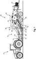
- FIG. 1 shows a schematic side view of a combination of an agricultural baler 10 in the form of a square baler and a tractor 12, wherein the baler 10 is pulled by the tractor 12 through a field.
- the tractor 12 has at the rear a known PTO 14, via which the baler 10 can be supplied with mechanical drive energy.
- the baler 10 working units such as a pickup 20, a cutting rotor 22, a Raffer 24, a plunger 26 and a knotter device 28 through which the crop 16 promoted and / or processed.
- the pickup 20 is used to record on the field floor - usually in the form of a so-called swath - lying crop 16 and supply this to the downstream conveying and / or processing units.
- the thus picked crop 16 reaches after leaving the pickup 20, the cutting rotor 22, which causes a further crushing of the crop 16. Subsequently, the crop 16 passes into a feed channel in which a Raffer 24 by periodic filling and Sammelhubterrorismen performs a pre-compaction of the crop 16 and a promotion of the crop 16 in the pressing chamber 30.
- a plunger 32 is mounted translationally movable, which is offset by a plunger drive in oscillating movements. Pre-pressed square bales 18 are dropped from the rear of the baler 10 on the field.
- the working units of the baler 10, in particular the pickup 20, the cutting rotor 22, the gripper 24, the plunger 32 and the above the pressing chamber 30 arranged knotter 28 are driven by a central drive train 34 of the baler 10.
- This drive train 34 essentially comprises a shaft 36 which is connected to the PTO shaft 14 tractor 12 in Drive connection is, an input gear 38, a propeller shaft 40, an energy storage 42 in the form of a flywheel 44 and a main gear 46.
- a provided by the tractor 12 via the PTO 14 drive power is thus transmitted via the drive train 34 to the main gear 46 to from there to individual work units such as pickup 20, cutting rotor 22, Raffer 24, plunger 32 and knotter 28 of the baler 10 to be distributed.
- the baler 10 has an energy store 42 with a variable moment of inertia.
- the drive train 34 has a specifically increased moment of inertia through the energy accumulator 42 arranged between the propeller shaft 40 and the main transmission 46 in the form of the flywheel 44. This has the advantage that the tractor-side PTO shaft 14 is protected from periodic load peaks, resulting in particular from interactions by the drive of the plunger 32. Due to the increased moment of inertia, a higher mechanical effort for accelerating the drive train 34 is required when the baler 10 starts up.
- the variable moment of inertia can be reduced during the starting process, whereby a start of the baler 10 can be made more quickly.
- the moment of inertia can then be increased, for example, starting from a predetermined rotational speed of the drive train 34 and / or the flywheel 44, in particular to a maximum.
- braking and / or accelerating the drive train 34 may be required, for example, in the overload case of a working unit 20, 22, 24, 26, 28 as a blockage by crop or more generally in work interruptions.
- braking the drive train 34 and / or the flywheel 44 for example, by lowering the moment of inertia, first the rotational speed of the drive train 34 and / or the flywheel 44 can be raised, and then the moment of inertia can be increased.
- An energy store 42 with a variable moment of inertia in the form of a flywheel 44 can, for example, be scaffolded in addition to an existing flywheel.
- an energy storage device 42 may be formed with variable moment of inertia.
- the energy storage 42 is in each case in the form of a flywheel 44, which is rotatably mounted about a rotation axis 50.
- the flywheel 44 in this case has a plurality of mass elements 52, whose centers of gravity 54 are designed to be displaceable perpendicular to the axis of rotation 50 in the radial direction R.
- the mass elements 52 are arranged within the flywheel 44, in particular flush with the surface, within receiving openings 56.
- the mass elements 52 have a substantially cuboidal shape and are guided by first guide devices 58 in the form of side surfaces of the receiving openings 56 and prevented from rotating. Furthermore, the mass elements 52 are arranged on a second guide device 60 in the form of a rod and are guided in the radial direction R through this. Radially on the outside and / or inside, an elastic element 62 in the form of a spring is arranged on the mass element 52, which is supported relative to the flywheel 44, in particular within the receiving opening 56.
- Fig. 2a the flywheel 44 is shown with a reduced moment of inertia, wherein the mass elements 52 are each shown in a start position 64, radially inward.
- the mass elements 52 are displaced radially outward against the elastic members 62, whereby the moment of inertia of the flywheel is increased.
- the displacement of the mass elements 52 takes place translationally in the radial direction R.
- a maximum moment of inertia of the flywheel 44 is reached ( Fig. 2b ), when the mass elements 52 have reached their respective radially outside operating position 66.
- the mass elements 52 can be returned to the starting position 64 by the elastic elements 62.
- a displacement of the mass element 52 can also by means of an actuator (not shown), in particular speed-independent, take place.
- the second guide device 60 may be formed, for example, in the form of a spindle drive, whereby, for example, a speed-independent displacement of the mass element 52 can be made possible.
- the actuator can be controlled by the control device 48.
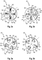
- the mass elements 52 are each pivotally mounted about a pivot axis 68.
- the center of gravity 54 of a mass element 52 is translationally and / or rotationally displaceable in the radial direction R into a start position and / or an operating position 66.
- the pivot axes 68 are arranged parallel to the axis of rotation 50 of the flywheel 44.
- the mass elements 52 are arranged on a surface of the flywheel 44.
- an elastic element 62 for example in the form of a tension or compression spring, is arranged between the mass element 52 and the third guide device 70, which is compressed from the start position 64 to the operating position 66 when the mass element 52 is displaced. Due to the elastic element 62, the mass element 52 can be transferred to the starting position again at a standstill or at a low rotational speed of the flywheel.
- the mass elements 52 may have an inhomogeneous structure, wherein the center of gravity 54 is arranged outside of a centroid of the mass element 52.
- the mass elements 52 may be formed, for example, pendulum-shaped and displaceable about a pivot axis.
Landscapes
- Life Sciences & Earth Sciences (AREA)
- Environmental Sciences (AREA)
- Harvester Elements (AREA)
- Harvesting Machines For Specific Crops (AREA)
Abstract
Description
- Die Erfindung betrifft eine landwirtschaftliche Ballenpresse gemäß dem Oberbegriff des Anspruches 1.
- Ballenpressen werden in der Landwirtschaft dazu eingesetzt beispielsweise im Schwad abgelegtes halmartiges Erntegut wie Stroh, Heu, Gras oder dergleichen aufzunehmen und zu Ballen zu pressen. Hierzu verfügen Ballenpressen über verschiedene Arbeitsaggregate, die der erforderlichen Förderung und/oder Verarbeitung des Ernteguts dienen. Die Arbeitsaggregate stehen üblicherweise mit einem zentralen Antriebsstrang der Ballenpresse in Antriebsverbindung.
- Eine derartige landwirtschaftliche Ballenpresse ist in Form einer Quaderballenpresse beispielsweise aus der
EP 0 819 375 A1 bekannt, welche eine zumindest einen Schneidrotor, einen Raffer und einen Presskolben aufweist, welche über einen zentralen Antriebsstrang antreibbar sind. Die Ballenpresse wird von einem Traktor gezogen und ist antriebsstrangseitig mit einer Zapfwelle des Traktors zum Antrieb der Ballenpresse verbunden. Der Antriebsstrang der Quaderballenpressen weist dabei einen Presskolbenantrieb auf. Dabei dient üblicherweise eine Kurbelwelle mit entsprechend angelenkter Pleuelstangenanordnung dazu, eine über Antriebswellen und beispielsweise einem Getriebe auf die Kurbelwelle übertragene Rotationsbewegung in eine translatorische Pendelbewegung des Presskolbens umzuformen. Die im Pressbetrieb ständig erfolgende Pendelbewegung des Presskolbens, der zur Erzielung einer gewünschten Wucht beim Auftreffen auf das Erntegut eine nicht unerhebliche Masse aufweisen muss, steht dabei in Wechselwirkung mit dem zugeordneten Antriebsstrang, so dass die periodischen Kolbenhübe eine ebenfalls periodische Rückwirkung auf den gesamten vorgelagerten Antriebsstrang ausüben. Zum Schutz zumindest einiger Komponenten des Antriebsstrangs, insbesondere zum Schutz des Zapfwellenantriebsstrangs des Traktors vor periodischen Lastspitzen ist dem Antriebsstrang von Quaderballenpressen daher ein Energiespeicher üblicherweise in Form eines Schwungrades zugeordnet. Dessen bewusst hoch gewähltes Trägheitsmoment sorgt dafür, dass die durch den Presskolbenantrieb bedingten periodischen Laststöße weitestgehend abgefangen werden können. In heutigen Quaderballenpressen verwendete Schwungräder weisen dazu beispielsweise Massen von einigen hundert Kilogramm mit einem entsprechend hohen Trägheitsmoment auf. - Das hohe Trägheitsmoment des Antriebsstranges der Ballenpresse hat jedoch den Nachteil, dass bei einem Anfahren der Ballenpresse ein verhältnismäßig hoher mechanischer Aufwand für die Beschleunigung erforderlich ist. Da der antreibende Traktor den Antriebsstrang nur langsam in Bewegung versetzen kann, zieht sich der Startvorgang durchaus über einen längeren Zeitraum hin und erfordert dabei eine hohe Antriebsleistung. Zudem kann während des Betriebs der Ballenpresse ein Abbremsen, ein Wiederbeschleunigen oder gar ein Neustart erforderlich sein, beispielsweise im Überlastungsfall einzelner Arbeits- und/oder Förderaggregate oder sonstigen Arbeitsunterbrechungen, was jeweils zu einer hohen Belastung des Antriebsstranges und des Antriebmotors des Zugfahrzeuges führt.
- Es ist daher eine Aufgabe der vorliegenden Erfindung, eine landwirtschaftliche Ballenpresse bereitzustellen, welche eine Reduzierung der Belastung des Antriebsstranges und ein verbessertes Betreiben der Ballenpresse ermöglicht.
- Die Lösung der Aufgabe erfolgt erfindungsgemäß durch die kennzeichnenden Merkmale des Anspruches 1. Vorteilhafte Ausgestaltungen der Erfindung sind in den Unteransprüchen angegeben.
- Die Aufgabe wird gelöst durch eine landwirtschaftliche Ballenpresse, insbesondere Quaderballenpresse, mit zumindest einem Arbeitsaggregat zur Verarbeitung und/oder Förderung von Erntegut, und einem Antriebsstrang zum Antrieb des mindestens einen Arbeitsaggregates, wobei dem Antriebsstrang mindestens ein Energiespeicher zugeordnet ist. Gemäß der Erfindung weist der Energiespeicher ein veränderbares Trägheitsmoment auf.
- Das Trägheitsmoment des mindestens einen Energiespeichers ist während des Betriebs und/oder im Stillstand der Ballenpresse variierbar, also veränderbar. Hierdurch kann das Trägheitsmoment des Energiespeichers beispielsweise im Stillstand und/oder bei einer niedrigen Drehzahl des Antriebsstranges geringer sein, als bei einer hohen Drehzahl. Dies hat den Vorteil, dass bei einem Anfahren und/oder Beschleunigen der Ballenpresse aufgrund des niedrigeren Trägheitsmoments ein geringeres Drehmoment und damit eine verringerte Antriebsleistung benötigt wird, als bei einem Antriebsstrang mit unveränderbarem, höheren Trägheitsmoment. Dies hat weiterhin den Vorteil, dass eine Belastung des Antriebsstranges während eines Beschleunigens und/oder Anfahrens des Antriebsstranges reduziert werden kann. Zudem können Drehmomentschwankungen durch ein entsprechendes Variieren des Trägheitsmomentes während des Betriebs der Ballenpresse ausgeglichen werden, wodurch ein Betrieb der Ballenpresse verbessert werden kann.
- In einer bevorzugten Ausgestaltung der Erfindung weist der Energiespeicher mindestens ein verlagerbares Masseelement auf, dessen Schwerpunkt zur Veränderung des Trägheitsmomentes des Energiespeichers zumindest in radialer Richtung verlagerbar ist. Das Trägheitsmoment eines Energiespeichers hängt u.a. von der Massenverteilung in Bezug auf beispielsweise eine Drehachse ab. Je weiter ein Masseelement dabei von der Drehachse in radialer Richtung entfernt ist, desto mehr trägt es zum Trägheitsmoment bei und so größer wird das Trägheitsmoment. Dadurch kann durch eine Verlagerung des Masseelementes eine Veränderung des Trägheitsmomentes ermöglicht werden. Dabei ist durch eine Verlagerung in radialer Richtung beispielsweise zu einer Drehachse hin, das Trägheitsmoment des Energiespeichers verkleinerbar und durch eine Verlagerung weg davon vergrößerbar.
- In einer bevorzugten Ausgestaltung der Erfindung ist das Masseelement translatorisch und/oder rotatorisch verlagerbar an dem Energiespeicher angeordnet. Eine translatorische Verlagerung eines Masseelementes kann beispielsweise in radialer und/oder tangentialer Richtung beispielsweise zu einer Drehachse des Energiespeichers erfolgen. Eine rotatorische Verlagerung kann beispielsweise durch ein Verschwenken des Masseelementes um eine Schwenkachse erfolgen. Durch eine translatorische und/oder rotatorische Verlagerung des Masseelementes relativ zu dem Energiespeicher kann eine konstruktiv günstige Verlagerung des Massenschwerpunktes des Masselelementes gewählt werden.
- Ferner ist bevorzugt vorgesehen, dass das Masseelement in eine Starposition und/oder eine Betriebsposition verbringbar ist. Eine Startposition kann dabei eine Position des Masseelementes sein, in der das Trägheitsmoment des Energiespeichers ein Minimum aufweist. In einer Betriebsposition des Masseelementes kann das Trägheitsmoment des Energiespeichers einen größeren Wert als in der Startposition und/oder ein Maximum aufweisen. Durch eine definierte Startposition des mindestens einen Masseelementes kann ein energieeffizientes Anfahren der Ballenpresse ermöglicht werden.
- Vorteilhafterweise ist das Masseelement selbstverstellend und/oder, beispielswiese mittels eines Aktors, aktiv verstellbar ausgebildet. Ein selbstverstellendes Masseelement kann in Abhängigkeit der Fliehkraft, insbesondere automatisch, verstellbar sein. Hierbei kann das Masseelement fliehkraftbedingt von der Startposition in eine Betriebsposition verlagert werden. Dies hat den Vorteil, dass keine weitere Steuerung oder Regelung notwendig ist, und das Masseelement beispielsweise bei einem Anhalten der Ballenpresse und oder des Energiespeichers selbsttätig in die Startposition zurückkehrt. Eine aktive Verstellung des Masseelementes, beispielsweise mittels eines elektrisch und/oder hydraulisch antreibbaren Aktors hat den Vorteil, dass eine genaue Steuerung des Trägheitsmomentes des Energiespeichers ermöglicht wird.
- In einer bevorzugten Ausgestaltung der Erfindung ist dem Masseelement mindestens ein elastisch verformbareres Element zugeordnet. Das Masseelement ist durch das mindestens eine elastische Element, insbesondere bei einem Stillstand der Ballenpresse und/oder des Energiespeichers, verlagerbar, insbesondere in eine Startposition oder Betriebsposition. Ein elastisches Element kann in Form einer Feder, beispielsweise Zug- oder Druckfeder, und/oder eines Kunststoffelementes ausgebildet sein. Bei einer Verlagerung des Masseelementes kann das elastische Element verformt werden, wodurch beispielsweise eine konstruktiv einfache Rückstellung des Masseelementes in die Startposition bewirkt werden kann.
- In einer besonders bevorzugten Ausgestaltung der Erfindung ist dem Masseelement mindestens eine Führungsvorrichtung zur Führung der Verlagerung des Masseelementes zugeordnet. Die Führungsvorrichtung kann in Form einer Profilierung, Führungsflächen und/oder eines Anschlags ausgebildet sein. Dies hat den Vorteil, dass unkontrollierte Bewegungen des Masseelementes vermieden werden können oder auch definierte Positionen, beispielsweise die Startposition, bestimmt werden können.
- In einer besonders bevorzugten Ausgestaltung der Erfindung ist der mindestens eine Energiespeicher in Form eines Schwungrades ausgebildet, welches um eine Drehachse drehbar gelagert ist. Ein Schwungrad stellt dabei einen konstruktiv einfachen und robusten Energiespeicher dar, dessen Trägheitsmoment durch verlagerbare Masseelemente auf einfache Weise veränderbar ist. Zudem ist das Masseelement vorteilhafterweise, insbesondere teilweise, innerhalb oder auf einer Oberfläche des Energiespeichers angeordnet, wodurch eine bauraumsparende Anordnung des mindestens einen Masseelementes an dem Schwungrad ermöglicht wird.
- In einer besonders bevorzugten Ausgestaltung der Erfindung ist eine Steuervorrichtung zum, insbesondere automatischen, Verlagern des mindestens einen Masseelementes vorgesehen. Durch die Steuervorrichtung können ein oder mehrere Masseelemente, insbesondere einzeln oder gemeinsam, aktiv verstellt werden, beispielsweise durch eine entsprechende Ansteuerung von einem den jeweiligen Masseelementen zugeordneten Aktor oder Aktoren. Dies ermöglicht neben einem automatischen Anfahren einer Startposition von Masseelementen eine vorausschauende Änderung des Trägheitsmomentes des Energiespeichers im Betrieb der Ballenpresse. So kann beispielsweise eine Drehzahl des Schwungrades durch eine Verlagerung von Masseelementen verändert werden. Zudem hat eine einzelne Verlagerung von Masselementen den Vorteil, dass hierdurch ein Schwungrad ausgewichtet werden kann, wodurch beispielsweise Belastungen auf dessen Lagerung verringert und die Lebensdauer erhöht werden können.
- Nachfolgend wird die Erfindung unter Bezugnahme auf die anliegenden Zeichnungen näher erläutert.
- Es zeigt:
- Fig. 1:
- eine Kombination aus einem Traktor und einer Ballenpresse in schematischer Seitenansicht;
- Fig. 2a,b:
- eine schematische Detailansicht eines ersten Schwungrades in einer Startposition und einer Betriebsposition; und
- Fig. 3a,b:
- eine schematische Detailansicht eines zweiten Schwungrades in einer Startposition und einer Betriebsposition.
-
Figur 1 zeigt in einer schematischen Seitenansicht eine Kombination aus einer landwirtschaftlichen Ballenpresse 10 in Form einer Quaderballenpresse und einem Traktor 12, wobei die Ballenpresse 10 von dem Traktor 12 über ein Feld gezogen wird. Der Traktor 12 weist heckseitig einen an sich bekannten Zapfwellenabtrieb 14 auf, über den die Ballenpresse 10 mit mechanischer Antriebsenergie versorgt werden kann. Zur Verarbeitung von Erntegut 16 zu Quaderballen 18 weist die Ballenpresse 10 Arbeitsaggregate wie eine Pickup 20, einen Schneidrotor 22, einen Raffer 24, einen Presskolben 26 und eine Knotereinrichtung 28 auf, durch welche das Erntegut 16 gefördert und/oder bearbeitet wird. Dabei dient die Pickup 20 dazu, auf dem Feldboden - zumeist in Form eines sogenannten Schwads - liegendes Erntegut 16 aufzunehmen und dieses den nachgelagerten Förder- und/oder Verarbeitungsaggregaten zuzuführen. - Das so aufgenommene Erntegut 16 erreicht nach Verlassen der Pickup 20 den Schneidrotor 22, welcher eine weitere Zerkleinerung des Ernteguts 16 bewirkt. Anschließend gelangt das Erntegut 16 in einen Zuführkanal, in welchem ein Raffer 24 durch periodische Füll- und Sammelhubbewegungen eine Vorverdichtung des Erntegutes 16 und eine Förderung des Ernteguts 16 in die Presskammer 30 durchführt. In der Presskammer 30 ist ein Presskolben 32 translatorisch beweglich gelagert, welcher über einen Presskolbenantrieb in oszillierende Bewegungen versetzt wird. Fertig gepresste Quaderballen 18 werden heckseitig aus der Ballenpresse 10 auf das Feld abgeworfen.
- Die Arbeitsaggregate der Ballenpresse 10, insbesondere die Pickup 20, der Schneidrotor 22, der Raffer 24, der Presskolben 32 sowie die oberhalb der Presskammer 30 angeordnete Knotereinrichtung 28, werden über einen zentralen Antriebsstrang 34 der Ballenpresse 10 angetrieben. Dieser Antriebsstrang 34 umfasst im Wesentlichen eine Welle 36, die mit der Zapfwelle 14 Traktors 12 in Antriebsverbindung steht, ein Eingangsgetriebe 38, eine Gelenkwelle 40, ein Energiespeicher 42 in Form eines Schwungrades 44 und ein Hauptgetriebe 46. Eine vom Traktor 12 über die Zapfwelle 14 bereitgestellte Antriebsleistung wird somit über den Antriebsstrang 34 zum Hauptgetriebe 46 übertragen, um von dort aus an einzelne Arbeitsaggregate wie Pickup 20, Schneidrotor 22, Raffer 24, Presskolben 32 und Knotereinrichtung 28 der Ballenpresse 10 verteilt zu werden.
- Erfindungsgemäß weist die Ballenpresse 10 einen Energiespeicher 42 mit einem variablen Trägheitsmoment auf. Der Antriebsstrang 34 weist durch den zwischen der Gelenkwelle 40 und dem Hauptgetriebe 46 angeordnete Energiespeicher 42 in Form des Schwungrades 44 ein gezielt erhöhtes Trägheitsmoment auf. Dieses hat den Vorteil, dass die traktorseitige Zapfwelle 14 vor periodischen Lastspitzen geschützt wird, welche sich insbesondere aus Wechselwirkungen durch den Antrieb des Presskolbens 32 ergeben. Aufgrund des erhöhten Trägheitsmomentes wird bei einem Anfahren der Ballenpresse 10 ein höherer mechanischer Aufwand zur Beschleunigung des Antriebsstrangs 34 benötigt.
- Da der antreibende Traktor 12 den Antriebsstrang 34 - mitsamt davon angetriebenen Arbeitsaggregaten 20, 22, 24, 26, 28 - nur langsam in Bewegung versetzen kann, zieht sich der Startvorgang durchaus über einen nicht unerheblichen Zeitraum hin und erfordert dabei viel Energie. Bei einem erfindungsgemäßen Energiespeicher 42, besonders in Form eines Schwungrades 44, kann das variable Trägheitsmoment während des Startvorganges reduziert werden, wodurch ein Anfahren der Ballenpresse 10 zügiger erfolgen kann. Das Trägheitsmoment kann dann beispielsweise bei ab einer vorgegebenen Drehzahl des Antriebsstranges 34 und/oder des Schwungrades 44, insbesondere auf ein Maximum, erhöht werden.
- Während des Betriebs der Ballenpresse 10 kann ein Abbremsen und/oder Beschleunigen des Antriebsstrangs 34 erforderlich sein, beispielsweise im Überlastungsfall eines Arbeitsaggregates 20, 22, 24, 26, 28 wie einer Blockierungen durch Erntegut oder ganz allgemein bei Arbeitsunterbrechungen. Nach einem Abbremsen des Antriebsstranges 34 und/oder des Schwungrades 44 kann beispielsweise durch ein Absenken des Trägheitsmomentes zunächst die Drehzahl des Antriebsstranges 34 und/oder des Schwungrades 44 angehoben werden, und anschließend das Trägheitsmoment erhöht werden. Durch eine insbesondere automatische Reglung mittels einer traktor- und/oder pressenseitigen Steuervorrichtung 48 können auch Drehzahlschwankungen durch eine Veränderung des Trägheitsmomentes ausgeglichen werden. Ein Energiespeicher 42 mit variablem Trägheitsmoment in Form eines Schwungrades 44 kann beispielsweise zusätzlich zu einem bestehenden Schwungrad eingerüstet werden.
- In den
Fig. 2 und 3 sind verschiedenen Ausführungsbeispielen Möglichkeiten gezeigt, wie ein Energiespeicher 42 mit variablem Trägheitsmoment ausgebildet sein kann. Der Energiespeicher 42 ist dabei jeweils in Form eines Schwungrades 44 ausgebildet, welches um eine Drehachse 50 drehbar gelagert ist. Das Schwungrad 44 weist dabei mehrere Masseelemente 52 auf, deren Schwerpunkte 54 senkrecht zur Drehachse 50 in radialer Richtung R verlagerbar ausgestaltet sind. Die Masseelemente 52 sind dabei innerhalb des Schwungrades 44, insbesondere oberflächenbündig, innerhalb von Aufnahmeöffnungen 56 angeordnet. - Die Masseelemente 52 weisen eine im Wesentlichen quaderförmige Form auf und werden durch erste Führungsvorrichtungen 58 in Form von Seitenflächen der Aufnahmeöffnungen 56 geführt und an einer Drehbewegung gehindert. Weiterhin sind die Masseelemente 52 an einer zweiten Führungsvorrichtung 60 in Form eines Stabes angeordnet und werden in radialer Richtung R durch diesen geführt. Radial außenseitig und/oder innenseitig ist an dem Masseelemente 52 ein elastisches Element 62 in Form einer Feder angeordnet, welche gegenüber dem Schwungrad 44, insbesondere innerhalb der Aufnahmeöffnung 56, abgestützt ist.
- In
Fig. 2a ist das Schwungrad 44 mit einem verringerten Trägheitsmoment dargestellt, wobei die Masseelemente 52 jeweils in einer Startposition 64, radial innen, dargestellt sind. Bei einem Anfahren der Ballenpresse 10 und einer zunehmenden Drehzahl des Schwungrades 44 werden die Masselelemente 52 gegen die elastischen Elemente 62 nach radial außen verlagert, wodurch das Trägheitsmoment des Schwungrades erhöht wird. Die Verlagerung der Masseelemente 52 erfolgt dabei translatorisch in radialer Richtung R. Ein maximales Trägheitsmoment des Schwungrades 44 ist erreicht (Fig. 2b ), wenn die Masseelemente 52 ihre jeweilige radial außenseitige Betriebsposition 66 erreicht haben. - Bei einem Anhalten der Ballenpresse 10 und dem Schwungrad 44 können die Masseelemente 52 durch die elastischen Elemente 62 wieder in die Startposition 64 zurück verbracht werden. Eine Verlagerung des Masseelementes 52 kann auch mittels eines Aktors (nicht dargestellt), insbesondere drehzahlunabhängig, erfolgen. So kann die zweite Führungsvorrichtung 60 beispielsweise in Form eines Spindeltriebes ausgebildet sein, wodurch beispielsweise eine drehzahlunabhängige Verlagerung des Masseelementes 52 ermöglicht werden kann. Der Aktor kann dabei durch die Steuervorrichtung 48 gesteuert werden.
- In
Fig. 3a und 3b sind die Masseelementen 52 jeweils um eine Schwenkachse 68 schwenkbar gelagert. Hierdurch ist der Schwerpunkt 54 eines Masseelementes 52 translatorisch und/oder rotatorisch in radialer Richtung R in eine Startposition und/oder eine Betriebsposition 66 verlagerbar. Die Schenkachsen 68 sind parallel zu der Drehachse 50 des Schwungrades 44 angeordnet. Die Masseelemente 52 sind auf einer Oberfläche des Schwungrades 44 angeordnet. Durch eine dritte Führungsvorrichtung 70 in Form eines Anschlags wird eine Schwenkbewegung eines Masseelementes 52 in der Betriebsposition 66 begrenzt (Fig. 3b ). Zwischen dem Masseelement 52 und der dritten Führungsvorrichtung 70 ist dabei jeweils ein elastisches Element 62, beispielsweise in Form eines Zug- oder Druckfeder, angeordnet, welches bei einer Verlagerung des Masseelementes 52 von der Startposition 64 in die Betriebsposition 66 komprimiert wird. Durch das elastische Element 62 ist das Masseelement 52 bei einem Stillstand oder einer geringen Drehzahl des Schwungrades wieder in die Startposition überführbar. - Die Masseelemente 52 können einen inhomogenen Aufbau aufweisen, wobei der Schwerpunkt 54 außerhalb eines Flächenschwerpunktes des Masseelementes 52 angeordnet ist. Das Masseelemente 52 kann dabei beispielsweise pendelförmig ausgebildet und um eine Schwenkachse verlagerbar sein.
-
- 10
- Ballenpresse
- 12
- Traktor
- 14
- Zapfwellen_antrieb/_abtrieb
- 16
- Erntegut
- 18
- Quaderballen
- 20
- Pickup
- 22
- Schneidrotor
- 24
- Raffer
- 26
- Presskolben
- 28
- Knoterreinigung
- 30
- Presskammer
- 32
- Presskolben
- 34
- Antriebsstrang
- 36
- Welle
- 38
- Eingangsgetriebe
- 40
- Gelenkwelle
- 42
- Energiespeicher
- 44
- Schwungrad
- 46
- Hauptgetriebe
- 48
- Steuervorrichtung
- 50
- Drehachse
- 52
- Masseelemente
- 54
- Schwerpunkt
- 56
- Aufnahmeöffnung
- 58
- erste Führungsvorrichtung
- 60
- zweite Führungsvorrichtung
- 62
- elastisches Elemente
- 64
- Startposition
- 66
- Betriebsposition
- 68
- Schwenkachse
- 70
- dritte Führungsvorrichtung
- R
- radiale Richtung
Claims (10)
- Landwirtschaftliche Ballenpresse, insbesondere Quaderballenpresse, mit zumindest einem Arbeitsaggregat (20, 22, 24, 26, 28) zur Verarbeitung und/oder Förderung von Erntegut (16), und einem Antriebsstrang (34) zum Antrieb des mindestens einen Arbeitsaggregates (20, 22, 24, 26, 28), wobei dem Antriebsstrang (34) mindestens ein Energiespeicher (42) zugeordnet ist, dadurch gekennzeichnet, dass der Energiespeicher (42) ein variables Trägheitsmoment aufweist.
- Ballenpresse nach Anspruch 1, dadurch gekennzeichnet, dass der Energiespeicher (42) mindestens ein verlagerbares Masseelement (52) aufweist, dessen Schwerpunkt (54) zur Veränderung des Trägheitsmomentes des Energiespeichers (42) zumindest in radialer Richtung (R) verlagerbar ist.
- Ballenpresse nach Anspruch 1 oder 2, dadurch gekennzeichnet, dass das Masseelement (52) translatorisch und/oder rotatorisch verlagerbar an dem Energiespeicher (42) angeordnet ist.
- Ballenpresse nach einem der vorherigen Ansprüche, dadurch gekennzeichnet, dass das Masseelement (52) in eine Starposition (64) und/oder eine Betriebsposition (66) verbringbar ist.
- Ballenpresse nach einem der vorherigen Ansprüche, dadurch gekennzeichnet, dass das Masseelement (52) selbstverstellend und/oder, beispielswiese mittels eines Aktors (), aktiv verstellbar ausgebildet ist.
- Ballenpresse nach einem der vorherigen Ansprüche, dadurch gekennzeichnet, dass dem Masseelement (52) mindestens ein elastisch verformbareres Element (62) zugeordnet ist.
- Ballenpresse nach einem der vorherigen Ansprüche, dadurch gekennzeichnet, dass dem Masseelement (52) mindestens eine Führungsvorrichtung (58, 60, 70) zur Führung der Verlagerung des Masseelementes (52) zugeordnet ist.
- Ballenpresse nach einem der vorherigen Ansprüche, dadurch gekennzeichnet, dass der mindestens eine Energiespeicher (42) in Form eines Schwungrades (44) ausgebildet ist, welches um eine Drehachse (50) drehbar gelagert ist.
- Ballenpresse nach einem der vorherigen Ansprüche, dadurch gekennzeichnet, dass das Masseelement (52), insbesondere teilweise, innerhalb oder auf einer Oberfläche des Energiespeichers (42) angeordnet ist.
- Ballenpresse nach einem der vorherigen Ansprüche, dadurch gekennzeichnet, dass eine Steuervorrichtung (48) zum, insbesondere automatischen, Verlagern des mindestens einen Masseelementes (52) vorgesehen ist.
Applications Claiming Priority (1)
| Application Number | Priority Date | Filing Date | Title |
|---|---|---|---|
| DE102017109782.1A DE102017109782A1 (de) | 2017-05-08 | 2017-05-08 | Ballenpresse |
Publications (3)
| Publication Number | Publication Date |
|---|---|
| EP3400786A1 true EP3400786A1 (de) | 2018-11-14 |
| EP3400786B1 EP3400786B1 (de) | 2019-12-04 |
| EP3400786B2 EP3400786B2 (de) | 2022-09-21 |
Family
ID=61007558
Family Applications (1)
| Application Number | Title | Priority Date | Filing Date |
|---|---|---|---|
| EP18152445.5A Active EP3400786B2 (de) | 2017-05-08 | 2018-01-19 | Ballenpresse |
Country Status (2)
| Country | Link |
|---|---|
| EP (1) | EP3400786B2 (de) |
| DE (1) | DE102017109782A1 (de) |
Cited By (1)
| Publication number | Priority date | Publication date | Assignee | Title |
|---|---|---|---|---|
| DE102020125541A1 (de) | 2020-09-30 | 2022-03-31 | Usines Claas France S.A.S. | Landwirtschaftliche Quaderballenpresse |
Families Citing this family (2)
| Publication number | Priority date | Publication date | Assignee | Title |
|---|---|---|---|---|
| GB202115147D0 (en) * | 2021-10-21 | 2021-12-08 | Kuhn Geldrop Bv | Baler and a method of baling |
| EP4646919A1 (de) | 2024-05-08 | 2025-11-12 | Ortlinghaus-Werke GmbH | Kupplungsanordnung |
Citations (4)
| Publication number | Priority date | Publication date | Assignee | Title |
|---|---|---|---|---|
| US2685804A (en) * | 1950-11-24 | 1954-08-10 | Int Harvester Co | Friction drive flywheel for hay balers |
| EP0819375A1 (de) | 1996-07-16 | 1998-01-21 | Usines Claas France S.A. | Antriebssystem für landwirtschaftliche Grossballenpresse |
| EP2929776A1 (de) * | 2014-04-08 | 2015-10-14 | Usines Claas France S.A.S | Landwirtschaftliche Ballenpresse |
| EP3320769A1 (de) * | 2016-11-10 | 2018-05-16 | Deere & Company | Rechteckballenpresse mit einer die stopferbewegung kompensierenden gegenmasse |
-
2017
- 2017-05-08 DE DE102017109782.1A patent/DE102017109782A1/de not_active Withdrawn
-
2018
- 2018-01-19 EP EP18152445.5A patent/EP3400786B2/de active Active
Patent Citations (4)
| Publication number | Priority date | Publication date | Assignee | Title |
|---|---|---|---|---|
| US2685804A (en) * | 1950-11-24 | 1954-08-10 | Int Harvester Co | Friction drive flywheel for hay balers |
| EP0819375A1 (de) | 1996-07-16 | 1998-01-21 | Usines Claas France S.A. | Antriebssystem für landwirtschaftliche Grossballenpresse |
| EP2929776A1 (de) * | 2014-04-08 | 2015-10-14 | Usines Claas France S.A.S | Landwirtschaftliche Ballenpresse |
| EP3320769A1 (de) * | 2016-11-10 | 2018-05-16 | Deere & Company | Rechteckballenpresse mit einer die stopferbewegung kompensierenden gegenmasse |
Cited By (2)
| Publication number | Priority date | Publication date | Assignee | Title |
|---|---|---|---|---|
| DE102020125541A1 (de) | 2020-09-30 | 2022-03-31 | Usines Claas France S.A.S. | Landwirtschaftliche Quaderballenpresse |
| EP3977843A2 (de) | 2020-09-30 | 2022-04-06 | Usines Claas France S.A.S | Landwirtschaftliche quaderballenpresse |
Also Published As
| Publication number | Publication date |
|---|---|
| EP3400786B1 (de) | 2019-12-04 |
| DE102017109782A1 (de) | 2018-11-08 |
| EP3400786B2 (de) | 2022-09-21 |
Similar Documents
| Publication | Publication Date | Title |
|---|---|---|
| EP3563665B1 (de) | Rechteckballenpresse mit einer die stopferbewegung kompensierenden gegenmasse | |
| EP1974601B1 (de) | Großballenpresse | |
| EP0819374B1 (de) | Antriebssystem für landwirtschaftliche Grossballenpresse | |
| EP1769674B1 (de) | Landwirtschaftliche Kolbenpresse | |
| EP3400786B1 (de) | Ballenpresse | |
| EP2929776A1 (de) | Landwirtschaftliche Ballenpresse | |
| EP1008292A1 (de) | Verfahren und Vorrichtung zum Herstellen von hochverdichteten Rundballen aus landwirtschaftlichen Erntegütern | |
| EP2243349A2 (de) | Rundballenpresse | |
| EP4151077B1 (de) | Getriebeanordnung zum antreiben eines presskolbens einer quaderballenpresse | |
| EP0819375B1 (de) | Antriebssystem für landwirtschaftliche Grossballenpresse | |
| EP1825742A1 (de) | Verfahren und Vorrichtung zum Verdichten von abgeerntetem Erntegut zur Silageerzeugung | |
| EP4385312B1 (de) | Quaderballenpresse | |
| EP4385311B1 (de) | Getriebeanordnung für eine quaderballenpresse | |
| EP2995192B1 (de) | Quaderballenpresse | |
| EP3977843B1 (de) | Landwirtschaftliche quaderballenpresse | |
| DE102020211498A1 (de) | Drehmomentglättvorrichtungen für grossquaderballenpressen | |
| DE102021116061A1 (de) | Antriebsstrangbaugruppe zum Antreiben eines Arbeitsaggregats mit schwankender Last | |
| DE102025119441A1 (de) | Landwirtschaftliche ballenpresse | |
| EP4588336A1 (de) | Bindeeinrichtung für eine quaderballenpresse | |
| EP4588335A1 (de) | Bindeeinrichtung für eine quaderballenpresse | |
| EP4275478A1 (de) | Verfahren zum betreiben einer rundballenpresse sowie rundballenpresse | |
| EP4646919A1 (de) | Kupplungsanordnung | |
| DE102010036801A1 (de) | Antrieb für eine Überladeeinrichtung einer landwirtschaftlichen Erntemaschine | |
| DE1627903B2 (de) | Presse zum Verdichten von faserigen Futterstoffen |
Legal Events
| Date | Code | Title | Description |
|---|---|---|---|
| PUAI | Public reference made under article 153(3) epc to a published international application that has entered the european phase |
Free format text: ORIGINAL CODE: 0009012 |
|
| STAA | Information on the status of an ep patent application or granted ep patent |
Free format text: STATUS: THE APPLICATION HAS BEEN PUBLISHED |
|
| AK | Designated contracting states |
Kind code of ref document: A1 Designated state(s): AL AT BE BG CH CY CZ DE DK EE ES FI FR GB GR HR HU IE IS IT LI LT LU LV MC MK MT NL NO PL PT RO RS SE SI SK SM TR |
|
| AX | Request for extension of the european patent |
Extension state: BA ME |
|
| STAA | Information on the status of an ep patent application or granted ep patent |
Free format text: STATUS: REQUEST FOR EXAMINATION WAS MADE |
|
| 17P | Request for examination filed |
Effective date: 20190514 |
|
| RBV | Designated contracting states (corrected) |
Designated state(s): AL AT BE BG CH CY CZ DE DK EE ES FI FR GB GR HR HU IE IS IT LI LT LU LV MC MK MT NL NO PL PT RO RS SE SI SK SM TR |
|
| GRAP | Despatch of communication of intention to grant a patent |
Free format text: ORIGINAL CODE: EPIDOSNIGR1 |
|
| STAA | Information on the status of an ep patent application or granted ep patent |
Free format text: STATUS: GRANT OF PATENT IS INTENDED |
|
| RIC1 | Information provided on ipc code assigned before grant |
Ipc: A01F 15/08 20060101AFI20190702BHEP |
|
| INTG | Intention to grant announced |
Effective date: 20190805 |
|
| GRAS | Grant fee paid |
Free format text: ORIGINAL CODE: EPIDOSNIGR3 |
|
| GRAA | (expected) grant |
Free format text: ORIGINAL CODE: 0009210 |
|
| STAA | Information on the status of an ep patent application or granted ep patent |
Free format text: STATUS: THE PATENT HAS BEEN GRANTED |
|
| AK | Designated contracting states |
Kind code of ref document: B1 Designated state(s): AL AT BE BG CH CY CZ DE DK EE ES FI FR GB GR HR HU IE IS IT LI LT LU LV MC MK MT NL NO PL PT RO RS SE SI SK SM TR |
|
| REG | Reference to a national code |
Ref country code: GB Ref legal event code: FG4D Free format text: NOT ENGLISH |
|
| REG | Reference to a national code |
Ref country code: CH Ref legal event code: EP |
|
| REG | Reference to a national code |
Ref country code: AT Ref legal event code: REF Ref document number: 1208232 Country of ref document: AT Kind code of ref document: T Effective date: 20191215 |
|
| REG | Reference to a national code |
Ref country code: DE Ref legal event code: R096 Ref document number: 502018000446 Country of ref document: DE |
|
| REG | Reference to a national code |
Ref country code: IE Ref legal event code: FG4D Free format text: LANGUAGE OF EP DOCUMENT: GERMAN |
|
| REG | Reference to a national code |
Ref country code: NL Ref legal event code: MP Effective date: 20191204 |
|
| REG | Reference to a national code |
Ref country code: LT Ref legal event code: MG4D |
|
| PG25 | Lapsed in a contracting state [announced via postgrant information from national office to epo] |
Ref country code: LT Free format text: LAPSE BECAUSE OF FAILURE TO SUBMIT A TRANSLATION OF THE DESCRIPTION OR TO PAY THE FEE WITHIN THE PRESCRIBED TIME-LIMIT Effective date: 20191204 Ref country code: GR Free format text: LAPSE BECAUSE OF FAILURE TO SUBMIT A TRANSLATION OF THE DESCRIPTION OR TO PAY THE FEE WITHIN THE PRESCRIBED TIME-LIMIT Effective date: 20200305 Ref country code: NO Free format text: LAPSE BECAUSE OF FAILURE TO SUBMIT A TRANSLATION OF THE DESCRIPTION OR TO PAY THE FEE WITHIN THE PRESCRIBED TIME-LIMIT Effective date: 20200304 Ref country code: SE Free format text: LAPSE BECAUSE OF FAILURE TO SUBMIT A TRANSLATION OF THE DESCRIPTION OR TO PAY THE FEE WITHIN THE PRESCRIBED TIME-LIMIT Effective date: 20191204 Ref country code: LV Free format text: LAPSE BECAUSE OF FAILURE TO SUBMIT A TRANSLATION OF THE DESCRIPTION OR TO PAY THE FEE WITHIN THE PRESCRIBED TIME-LIMIT Effective date: 20191204 Ref country code: FI Free format text: LAPSE BECAUSE OF FAILURE TO SUBMIT A TRANSLATION OF THE DESCRIPTION OR TO PAY THE FEE WITHIN THE PRESCRIBED TIME-LIMIT Effective date: 20191204 Ref country code: BG Free format text: LAPSE BECAUSE OF FAILURE TO SUBMIT A TRANSLATION OF THE DESCRIPTION OR TO PAY THE FEE WITHIN THE PRESCRIBED TIME-LIMIT Effective date: 20200304 |
|
| PG25 | Lapsed in a contracting state [announced via postgrant information from national office to epo] |
Ref country code: RS Free format text: LAPSE BECAUSE OF FAILURE TO SUBMIT A TRANSLATION OF THE DESCRIPTION OR TO PAY THE FEE WITHIN THE PRESCRIBED TIME-LIMIT Effective date: 20191204 Ref country code: HR Free format text: LAPSE BECAUSE OF FAILURE TO SUBMIT A TRANSLATION OF THE DESCRIPTION OR TO PAY THE FEE WITHIN THE PRESCRIBED TIME-LIMIT Effective date: 20191204 |
|
| PG25 | Lapsed in a contracting state [announced via postgrant information from national office to epo] |
Ref country code: AL Free format text: LAPSE BECAUSE OF FAILURE TO SUBMIT A TRANSLATION OF THE DESCRIPTION OR TO PAY THE FEE WITHIN THE PRESCRIBED TIME-LIMIT Effective date: 20191204 |
|
| PG25 | Lapsed in a contracting state [announced via postgrant information from national office to epo] |
Ref country code: EE Free format text: LAPSE BECAUSE OF FAILURE TO SUBMIT A TRANSLATION OF THE DESCRIPTION OR TO PAY THE FEE WITHIN THE PRESCRIBED TIME-LIMIT Effective date: 20191204 Ref country code: ES Free format text: LAPSE BECAUSE OF FAILURE TO SUBMIT A TRANSLATION OF THE DESCRIPTION OR TO PAY THE FEE WITHIN THE PRESCRIBED TIME-LIMIT Effective date: 20191204 Ref country code: PT Free format text: LAPSE BECAUSE OF FAILURE TO SUBMIT A TRANSLATION OF THE DESCRIPTION OR TO PAY THE FEE WITHIN THE PRESCRIBED TIME-LIMIT Effective date: 20200429 Ref country code: CZ Free format text: LAPSE BECAUSE OF FAILURE TO SUBMIT A TRANSLATION OF THE DESCRIPTION OR TO PAY THE FEE WITHIN THE PRESCRIBED TIME-LIMIT Effective date: 20191204 Ref country code: RO Free format text: LAPSE BECAUSE OF FAILURE TO SUBMIT A TRANSLATION OF THE DESCRIPTION OR TO PAY THE FEE WITHIN THE PRESCRIBED TIME-LIMIT Effective date: 20191204 Ref country code: NL Free format text: LAPSE BECAUSE OF FAILURE TO SUBMIT A TRANSLATION OF THE DESCRIPTION OR TO PAY THE FEE WITHIN THE PRESCRIBED TIME-LIMIT Effective date: 20191204 |
|
| REG | Reference to a national code |
Ref country code: DE Ref legal event code: R026 Ref document number: 502018000446 Country of ref document: DE |
|
| PLBI | Opposition filed |
Free format text: ORIGINAL CODE: 0009260 |
|
| PG25 | Lapsed in a contracting state [announced via postgrant information from national office to epo] |
Ref country code: SM Free format text: LAPSE BECAUSE OF FAILURE TO SUBMIT A TRANSLATION OF THE DESCRIPTION OR TO PAY THE FEE WITHIN THE PRESCRIBED TIME-LIMIT Effective date: 20191204 Ref country code: IS Free format text: LAPSE BECAUSE OF FAILURE TO SUBMIT A TRANSLATION OF THE DESCRIPTION OR TO PAY THE FEE WITHIN THE PRESCRIBED TIME-LIMIT Effective date: 20200404 Ref country code: SK Free format text: LAPSE BECAUSE OF FAILURE TO SUBMIT A TRANSLATION OF THE DESCRIPTION OR TO PAY THE FEE WITHIN THE PRESCRIBED TIME-LIMIT Effective date: 20191204 |
|
| PLAX | Notice of opposition and request to file observation + time limit sent |
Free format text: ORIGINAL CODE: EPIDOSNOBS2 |
|
| 26 | Opposition filed |
Opponent name: DEERE & COMPANY/JOHN DEERE GMBH & CO. KG Effective date: 20200826 |
|
| PG25 | Lapsed in a contracting state [announced via postgrant information from national office to epo] |
Ref country code: MC Free format text: LAPSE BECAUSE OF FAILURE TO SUBMIT A TRANSLATION OF THE DESCRIPTION OR TO PAY THE FEE WITHIN THE PRESCRIBED TIME-LIMIT Effective date: 20191204 |
|
| PG25 | Lapsed in a contracting state [announced via postgrant information from national office to epo] |
Ref country code: LU Free format text: LAPSE BECAUSE OF NON-PAYMENT OF DUE FEES Effective date: 20200119 Ref country code: DK Free format text: LAPSE BECAUSE OF FAILURE TO SUBMIT A TRANSLATION OF THE DESCRIPTION OR TO PAY THE FEE WITHIN THE PRESCRIBED TIME-LIMIT Effective date: 20191204 |
|
| PG25 | Lapsed in a contracting state [announced via postgrant information from national office to epo] |
Ref country code: SI Free format text: LAPSE BECAUSE OF FAILURE TO SUBMIT A TRANSLATION OF THE DESCRIPTION OR TO PAY THE FEE WITHIN THE PRESCRIBED TIME-LIMIT Effective date: 20191204 Ref country code: PL Free format text: LAPSE BECAUSE OF FAILURE TO SUBMIT A TRANSLATION OF THE DESCRIPTION OR TO PAY THE FEE WITHIN THE PRESCRIBED TIME-LIMIT Effective date: 20191204 |
|
| PG25 | Lapsed in a contracting state [announced via postgrant information from national office to epo] |
Ref country code: IE Free format text: LAPSE BECAUSE OF NON-PAYMENT OF DUE FEES Effective date: 20200119 Ref country code: IT Free format text: LAPSE BECAUSE OF FAILURE TO SUBMIT A TRANSLATION OF THE DESCRIPTION OR TO PAY THE FEE WITHIN THE PRESCRIBED TIME-LIMIT Effective date: 20191204 |
|
| PLBB | Reply of patent proprietor to notice(s) of opposition received |
Free format text: ORIGINAL CODE: EPIDOSNOBS3 |
|
| REG | Reference to a national code |
Ref country code: CH Ref legal event code: PL |
|
| PG25 | Lapsed in a contracting state [announced via postgrant information from national office to epo] |
Ref country code: LI Free format text: LAPSE BECAUSE OF NON-PAYMENT OF DUE FEES Effective date: 20210131 Ref country code: CH Free format text: LAPSE BECAUSE OF NON-PAYMENT OF DUE FEES Effective date: 20210131 |
|
| PG25 | Lapsed in a contracting state [announced via postgrant information from national office to epo] |
Ref country code: TR Free format text: LAPSE BECAUSE OF FAILURE TO SUBMIT A TRANSLATION OF THE DESCRIPTION OR TO PAY THE FEE WITHIN THE PRESCRIBED TIME-LIMIT Effective date: 20191204 Ref country code: MT Free format text: LAPSE BECAUSE OF FAILURE TO SUBMIT A TRANSLATION OF THE DESCRIPTION OR TO PAY THE FEE WITHIN THE PRESCRIBED TIME-LIMIT Effective date: 20191204 Ref country code: CY Free format text: LAPSE BECAUSE OF FAILURE TO SUBMIT A TRANSLATION OF THE DESCRIPTION OR TO PAY THE FEE WITHIN THE PRESCRIBED TIME-LIMIT Effective date: 20191204 |
|
| PG25 | Lapsed in a contracting state [announced via postgrant information from national office to epo] |
Ref country code: MK Free format text: LAPSE BECAUSE OF FAILURE TO SUBMIT A TRANSLATION OF THE DESCRIPTION OR TO PAY THE FEE WITHIN THE PRESCRIBED TIME-LIMIT Effective date: 20191204 |
|
| PUAH | Patent maintained in amended form |
Free format text: ORIGINAL CODE: 0009272 |
|
| STAA | Information on the status of an ep patent application or granted ep patent |
Free format text: STATUS: PATENT MAINTAINED AS AMENDED |
|
| 27A | Patent maintained in amended form |
Effective date: 20220921 |
|
| AK | Designated contracting states |
Kind code of ref document: B2 Designated state(s): AL AT BE BG CH CY CZ DE DK EE ES FI FR GB GR HR HU IE IS IT LI LT LU LV MC MK MT NL NO PL PT RO RS SE SI SK SM TR |
|
| REG | Reference to a national code |
Ref country code: DE Ref legal event code: R102 Ref document number: 502018000446 Country of ref document: DE |
|
| GBPC | Gb: european patent ceased through non-payment of renewal fee |
Effective date: 20220119 |
|
| PG25 | Lapsed in a contracting state [announced via postgrant information from national office to epo] |
Ref country code: GB Free format text: LAPSE BECAUSE OF NON-PAYMENT OF DUE FEES Effective date: 20220119 |
|
| P01 | Opt-out of the competence of the unified patent court (upc) registered |
Effective date: 20230516 |
|
| REG | Reference to a national code |
Ref country code: AT Ref legal event code: MM01 Ref document number: 1208232 Country of ref document: AT Kind code of ref document: T Effective date: 20230119 |
|
| PG25 | Lapsed in a contracting state [announced via postgrant information from national office to epo] |
Ref country code: AT Free format text: LAPSE BECAUSE OF NON-PAYMENT OF DUE FEES Effective date: 20230119 |
|
| PG25 | Lapsed in a contracting state [announced via postgrant information from national office to epo] |
Ref country code: AT Free format text: LAPSE BECAUSE OF NON-PAYMENT OF DUE FEES Effective date: 20230119 |
|
| PGFP | Annual fee paid to national office [announced via postgrant information from national office to epo] |
Ref country code: DE Payment date: 20260121 Year of fee payment: 9 |
|
| PGFP | Annual fee paid to national office [announced via postgrant information from national office to epo] |
Ref country code: AT Payment date: 20260410 Year of fee payment: 5 |
|
| PGFP | Annual fee paid to national office [announced via postgrant information from national office to epo] |
Ref country code: BE Payment date: 20260121 Year of fee payment: 9 |
|
| PGFP | Annual fee paid to national office [announced via postgrant information from national office to epo] |
Ref country code: FR Payment date: 20260123 Year of fee payment: 9 |