EP3399603B1 - Method and apparatus for amplifying optical signals - Google Patents
Method and apparatus for amplifying optical signals Download PDFInfo
- Publication number
- EP3399603B1 EP3399603B1 EP18162187.1A EP18162187A EP3399603B1 EP 3399603 B1 EP3399603 B1 EP 3399603B1 EP 18162187 A EP18162187 A EP 18162187A EP 3399603 B1 EP3399603 B1 EP 3399603B1
- Authority
- EP
- European Patent Office
- Prior art keywords
- control module
- amplifier
- pump
- master
- control
- Prior art date
- Legal status (The legal status is an assumption and is not a legal conclusion. Google has not performed a legal analysis and makes no representation as to the accuracy of the status listed.)
- Ceased
Links
Images

Classifications
-
- H—ELECTRICITY
- H01—ELECTRIC ELEMENTS
- H01S—DEVICES USING THE PROCESS OF LIGHT AMPLIFICATION BY STIMULATED EMISSION OF RADIATION [LASER] TO AMPLIFY OR GENERATE LIGHT; DEVICES USING STIMULATED EMISSION OF ELECTROMAGNETIC RADIATION IN WAVE RANGES OTHER THAN OPTICAL
- H01S3/00—Lasers, i.e. devices using stimulated emission of electromagnetic radiation in the infrared, visible or ultraviolet wave range
- H01S3/09—Processes or apparatus for excitation, e.g. pumping
- H01S3/091—Processes or apparatus for excitation, e.g. pumping using optical pumping
- H01S3/094—Processes or apparatus for excitation, e.g. pumping using optical pumping by coherent light
- H01S3/094003—Processes or apparatus for excitation, e.g. pumping using optical pumping by coherent light the pumped medium being a fibre
-
- H—ELECTRICITY
- H01—ELECTRIC ELEMENTS
- H01S—DEVICES USING THE PROCESS OF LIGHT AMPLIFICATION BY STIMULATED EMISSION OF RADIATION [LASER] TO AMPLIFY OR GENERATE LIGHT; DEVICES USING STIMULATED EMISSION OF ELECTROMAGNETIC RADIATION IN WAVE RANGES OTHER THAN OPTICAL
- H01S3/00—Lasers, i.e. devices using stimulated emission of electromagnetic radiation in the infrared, visible or ultraviolet wave range
- H01S3/10—Controlling the intensity, frequency, phase, polarisation or direction of the emitted radiation, e.g. switching, gating, modulating or demodulating
- H01S3/13—Stabilisation of laser output parameters, e.g. frequency or amplitude
- H01S3/131—Stabilisation of laser output parameters, e.g. frequency or amplitude by controlling the active medium, e.g. by controlling the processes or apparatus for excitation
- H01S3/1312—Stabilisation of laser output parameters, e.g. frequency or amplitude by controlling the active medium, e.g. by controlling the processes or apparatus for excitation by controlling the optical pumping
-
- H—ELECTRICITY
- H01—ELECTRIC ELEMENTS
- H01S—DEVICES USING THE PROCESS OF LIGHT AMPLIFICATION BY STIMULATED EMISSION OF RADIATION [LASER] TO AMPLIFY OR GENERATE LIGHT; DEVICES USING STIMULATED EMISSION OF ELECTROMAGNETIC RADIATION IN WAVE RANGES OTHER THAN OPTICAL
- H01S3/00—Lasers, i.e. devices using stimulated emission of electromagnetic radiation in the infrared, visible or ultraviolet wave range
- H01S3/09—Processes or apparatus for excitation, e.g. pumping
- H01S3/091—Processes or apparatus for excitation, e.g. pumping using optical pumping
- H01S3/094—Processes or apparatus for excitation, e.g. pumping using optical pumping by coherent light
- H01S3/094003—Processes or apparatus for excitation, e.g. pumping using optical pumping by coherent light the pumped medium being a fibre
- H01S3/094011—Processes or apparatus for excitation, e.g. pumping using optical pumping by coherent light the pumped medium being a fibre with bidirectional pumping, i.e. with injection of the pump light from both two ends of the fibre
-
- H—ELECTRICITY
- H01—ELECTRIC ELEMENTS
- H01S—DEVICES USING THE PROCESS OF LIGHT AMPLIFICATION BY STIMULATED EMISSION OF RADIATION [LASER] TO AMPLIFY OR GENERATE LIGHT; DEVICES USING STIMULATED EMISSION OF ELECTROMAGNETIC RADIATION IN WAVE RANGES OTHER THAN OPTICAL
- H01S3/00—Lasers, i.e. devices using stimulated emission of electromagnetic radiation in the infrared, visible or ultraviolet wave range
- H01S3/10—Controlling the intensity, frequency, phase, polarisation or direction of the emitted radiation, e.g. switching, gating, modulating or demodulating
- H01S3/13—Stabilisation of laser output parameters, e.g. frequency or amplitude
- H01S3/1305—Feedback control systems
Definitions
- the present invention relates to a method and apparatus for amplifying optical communication signals and adjusting the amplifier.
- both incoming an outgoing signals are amplified at the line terminal equipment (LTE) to ensure adequate signal strength.
- Optical amplifiers such as erbium-doped fibre amplifiers (EDFAs)
- EDFAs erbium-doped fibre amplifiers
- a pump is applied at a wavelength which causes excitement of the erbium atoms in such a way that there is consequent amplification of the optical signal.
- Suitable lasers for the task are widely available, and are conventionally provided with integrated control electronics.
- EP0525684 discloses an optical feedback stabilisation system of a plurality of lasers in which a master laser is feedback stabilised, and the same stabilising commands are applied to the slave lasers.
- US5995275 discloses a single optical amplifier with two pump laser each having a control module.
- a method of adjusting the gain of an optical amplifier using a plurality of pump lasers controlled by a plurality of respective control modules comprising the steps of:
- the operational parameter is an applied input current.
- the operational parameter may be the output of the pump lasers.
- the step of adjusting the output of each of the remaining pump lasers comprises adjusting the operational parameter of each of the remaining pump lasers towards the operational parameter of the pump laser associated with the master control module.
- an apparatus for amplifying optical communication signals comprising a plurality of pump lasers controlled by a plurality of control modules , wherein the apparatus is configured to perform the method of the first aspect.
- a computer program product comprising computer executable code for implementing the method of the first aspect.
- FIG. 1 shows a schematic view of the conventional structure of an optical amplifier used in submarine optical communications.
- two pump lasers are provided for redundancy.
- Each pump laser and its associated control electronics are integrated as distinct modules which are connected to the optical amplifier by optical fibre connections.
- Replacement of a laser or its control electronics consequently involves replacement of both and is made arduous not only by the laser safety issues involved in disturbing the optical connection but also by the extreme susceptibility of laser-carrying optical fibres to dirt. Were dust to enter the fibre during the replacement process the performance of the replacement module would be severely compromised.
- the replacement of lasers or their control electronics in conventional systems can be time consuming and consequently expensive.
- pump lasers In recent times, significant improvements have been made to the reliability of the pump lasers. Moreover, the life of pump lasers is increased when they are operated below their maximum power, further increasing their reliability in a system that typically provides two pumps for each amplifier. Consequently, if suitably rated pump lasers are used, it is now possible to produce pump laser pairs that satisfy the design life requirements typically set for submarine optical amplifiers.
- control electronics are less reliable than typical amplifier requirements. Since in conventional systems the lasers and control electronics are typically integrated, pump lasers are often replaced during the amplifier lifetime unnecessarily.
- the present invention overcomes this problem by separating the pump laser and its control electronics, allowing the electronics to be replaced separately. Moreover, because of their improved reliability, the pump lasers may be integrated with the EDFA into an integrated amplifier module. Such a module contains all the required optical pathways, negating the need for external optical connections. Consequently, the control electronics may be replaced without any laser safety issues.
- FIGS 2 to 4 show a preferred embodiment of the present invention.
- two amplifier modules and two control modules are integrated on a single circuit pack.
- Each amplifier module contains an EDFA and two pump lasers, with each pump laser in a single amplifier module being controlled by a separate control module.
- the control modules therefore, control a single pump laser in each amplifier module.
- the pump lasers are rated such that they may drive an EDFA alone, the provision of two lasers increases their lifetime and allows for redundancy. Nevertheless, it must be understood that the removal or failure of a single control module does not disable either amplifier module.
- the present invention therefore provides a system for replacing amplifier control circuitry that not only leaves all optical pathways unaffected but also leaves amplifier performance undiminished.
- each pump laser may be more than two pump lasers in each amplifier module, or any number of amplifier modules on a single circuit pack.
- control modules of the preferred embodiment utilise shared electronics to control a plurality of pump lasers, it should be understood that the control circuitry for each pump laser may be entirely independent. In all cases, however, the logical control of each pump laser is separate. Indeed, it would be possible to employ separate control modules for each pump laser if so desired. The only requirement in this regard is that each pump laser on a given amplifier module must be controlled by separately replaceable control circuitry.
- control modules have a simple electrical interface to the amplifier modules. This makes it very easy to provide simple microprocessor-based control modules that are compact and simple. The simplicity increases reliability and reduces heat dissipation.
- Each control module receives amplifier input and output power measurements and pump power measurements from the amplifier modules.
- Each control module can adjust the power of each pump (by altering its bias current) to control the overall amplifier output power or gain.
- the control modules co-operate to ensure the two pumps for each amplifier share the input current or the power equally.
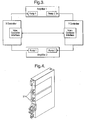
- FIG. 3 shows the interfaces between the control modules and with the amplifiers and their pumps.
- Each control module may have access to certain attributes of the pumps managed by the other control module so it can balance the pumps.
- the control modules may balance the pumps by passing the relevant pump attributes between each other.
- FIG 4 shows the mechanical arrangement of an embodiment of the present invention. Since the control modules hold only electronic components, this arrangement is simple (there being only electrical interfaces between the amplifier modules and the control modules).
- the control modules 31 are able to slide out from the front of the Circuit Pack allowing replacement to take just a few seconds. All optical connections are on the main part of the Circuit Pack so are not affected by control module replacement.
- control modules operate the pump lasers in each amplifier module in a master/slave arrangement; the master maintains the overall amplifier gain/power (by controlling pump power) whilst the slave balances the pumps (using either their bias currents or output power) to equalise the pump laser ageing.
- Envisaged indications that are passed between the control modules include:
- Each control module deems the other to be operational under the following circumstances: the other controller is present; the other controller is operating (its active indicator is on); and the other controller is sending regular status messages.
- the status indicatorss are passed between the control modules at a high rate in order to allow a rapid response.
- the fastest possible reaction time will clearly be the repetition rate of the amplifier control loop controlling the signal applied to the pump lasers.
- the election may be controlled by a simple algorithm that recognises whether a master already exists, and, if it detects one, adopts the role of slave. If initially both control modules adopt the role of master, one module may be biased to back down and become the slave while the other is biased to remain as the master. If the controllers are labelled X and Y, and the Y controller is biased to back down, an example algorithm followed by each controller may be expressed as follows:
- the master control module uses the common PID (Proportional, Integral, Derivative) control loop algorithm.
- the amplifier output power is the controlled variable whilst the pump bias current is the control variable. If the amplifier is in constant gain mode then the desired output power is calculated from the amplifier input power and desired gain.
- PID Proportional, Integral, Derivative
- the slave makes small adjustments to its pump control to balance the wear on the pump lasers.
- the adjustments may be made in dependence on the output levels of the pump lasers or on the level of the bias currents driving them.
- the applied bias current level is adopted since it negates the need for electronic pump output measurement devices within the integrated pump amplifier module. Moreover, it is typically easier to obtain reliable and accurate measurements of currents than laser outputs.
- Each adjustment moves the slave pump level towards the master pump level, with the ultimate aim of equalising the two levels.
- a further advantage of using bias currents rather than output powers as the relevant levels arises from the possibility of differences in the ageing rate of each laser. In such a scenario, equalising the power output of the lasers would have the effect of driving a more worn laser at a higher current than the other, thus increasing the likelihood of further differentiation in the ageing rates of the two lasers.
- the slave adjustments cause a small error in the amplifier output gain which is subsequently detected and corrected by the master power control loop.
- the magnitude of each adjustment is set to be very small so that the impact on the amplifier power/gain is negligible.
- the slave may have some control over the output power as well as the balance between the pump lasers. This may improve reaction times when the master fails, since the slave need not directly detect this before ensuring an adequate amplifier output. However, if the slave is too sensitive to the overall input any difference between the amplifier output measured by the master and the slave is found to force continual imbalances between the pumps. It is therefore preferable that, if the slave is to control output power at all, it does so with a large deadband. When the error between desired and actual power is within the deadband, the slave then balances the pumps.
- the status indications of each control module will be passed to all of the other control modules. This may be done over multi-drop links (i.e. a single transmission link from one module will be received by the remaining modules) or across any available communications bus. Any links are preferably duplicated for redundancy.
Landscapes
- Physics & Mathematics (AREA)
- Electromagnetism (AREA)
- Engineering & Computer Science (AREA)
- Plasma & Fusion (AREA)
- Optics & Photonics (AREA)
- Lasers (AREA)
- Semiconductor Lasers (AREA)
Description
- The present invention relates to a method and apparatus for amplifying optical communication signals and adjusting the amplifier.
- In optical transmission systems, both incoming an outgoing signals are amplified at the line terminal equipment (LTE) to ensure adequate signal strength. Optical amplifiers, such as erbium-doped fibre amplifiers (EDFAs), are now in widespread use to achieve this aim. When the optical signal passes through an EDFA a pump is applied at a wavelength which causes excitement of the erbium atoms in such a way that there is consequent amplification of the optical signal. Suitable lasers for the task are widely available, and are conventionally provided with integrated control electronics.
- Traditionally, when designing high-reliability optical amplifiers for use in Submarine LTEs, the pump lasers and their associated electronics are duplicated to provide redundancy should one fail. They are also replaceable. Since they are integrated, failure of either a pump or of its control electronics requires replacement of both. As the pump laser must clearly be optically connected to the EDFA, this requires optical fibres to be disconnected creating a potential safety hazard.
US2003174390 discloses a method for adjusting the gain of an optical amplifier using a plurality of pump lasers controlled by a controller, comprising the steps of monitoring the output of the amplifier and adjusting an operational parameter of the pump lasers such that the gain of the optical amplifier is equal to a predetermined value.EP0525684 discloses an optical feedback stabilisation system of a plurality of lasers in which a master laser is feedback stabilised, and the same stabilising commands are applied to the slave lasers.US5995275 discloses a single optical amplifier with two pump laser each having a control module. - The invention is as defined in the appended claims. According to a first aspect of the present invention, there is provided a method of adjusting the gain of an optical amplifier using a plurality of pump lasers controlled by a plurality of respective control modules, comprising the steps of:
- electing which of the control modules is a master control module;
- adjusting an operational parameter of the pump laser associated with the master control module towards the point at which the gain of the optical amplifier is equal to a predetermined ideal value; and,
- adjusting the operational parameter of each of the remaining pump lasers towards the point at which the operational parameters of all the pump lasers are equal.
- Preferably, the operational parameter is an applied input current. However, it is also envisaged that the operational parameter may be the output of the pump lasers.
- Preferably the step of adjusting the output of each of the remaining pump lasers comprises adjusting the operational parameter of each of the remaining pump lasers towards the operational parameter of the pump laser associated with the master control module.
- According to a second aspect of the invention, there is provided an apparatus for amplifying optical communication signals, comprising a plurality of pump lasers controlled by a plurality of control modules , wherein the apparatus is configured to perform the method of the first aspect.
- According to a third aspect of the present invention, there is provided a computer program product comprising computer executable code for implementing the method of the first aspect.
- Examples of the present invention will now be described in detail with reference to the accompanying drawings, in which:
-
Figure 1 is a schematic view of the configuration of a typical prior art optical amplifier; -
Figure 2 is a schematic view of a dual amplifier circuit pack in accordance with one embodiment of the present invention; -
Figure 3 is a schematic view of the interface between pump lasers and control modules in accordance with one embodiment of the present invention; and, -
Figure 4 is a view of the mechanical arrangement of a dual amplifier circuit pack in accordance with one embodiment of the present invention. -
Figure 1 shows a schematic view of the conventional structure of an optical amplifier used in submarine optical communications. As can be seen, two pump lasers are provided for redundancy. Each pump laser and its associated control electronics are integrated as distinct modules which are connected to the optical amplifier by optical fibre connections. Replacement of a laser or its control electronics consequently involves replacement of both and is made arduous not only by the laser safety issues involved in disturbing the optical connection but also by the extreme susceptibility of laser-carrying optical fibres to dirt. Were dust to enter the fibre during the replacement process the performance of the replacement module would be severely compromised. As a result of the care needed, the replacement of lasers or their control electronics in conventional systems can be time consuming and consequently expensive. - In recent times, significant improvements have been made to the reliability of the pump lasers. Moreover, the life of pump lasers is increased when they are operated below their maximum power, further increasing their reliability in a system that typically provides two pumps for each amplifier. Consequently, if suitably rated pump lasers are used, it is now possible to produce pump laser pairs that satisfy the design life requirements typically set for submarine optical amplifiers.
- Nevertheless, the control electronics are less reliable than typical amplifier requirements. Since in conventional systems the lasers and control electronics are typically integrated, pump lasers are often replaced during the amplifier lifetime unnecessarily.
- The present invention overcomes this problem by separating the pump laser and its control electronics, allowing the electronics to be replaced separately. Moreover, because of their improved reliability, the pump lasers may be integrated with the EDFA into an integrated amplifier module. Such a module contains all the required optical pathways, negating the need for external optical connections. Consequently, the control electronics may be replaced without any laser safety issues.
-
Figures 2 to 4 show a preferred embodiment of the present invention. In this embodiment two amplifier modules and two control modules are integrated on a single circuit pack. Each amplifier module contains an EDFA and two pump lasers, with each pump laser in a single amplifier module being controlled by a separate control module. The control modules, therefore, control a single pump laser in each amplifier module. Though the pump lasers are rated such that they may drive an EDFA alone, the provision of two lasers increases their lifetime and allows for redundancy. Nevertheless, it must be understood that the removal or failure of a single control module does not disable either amplifier module. - The present invention therefore provides a system for replacing amplifier control circuitry that not only leaves all optical pathways unaffected but also leaves amplifier performance undiminished.
- It is to be understood that the embodiment described by the figures is not the only envisaged implementation of the present invention. There may, for example, be more than two pump lasers in each amplifier module, or any number of amplifier modules on a single circuit pack. Moreover, though the control modules of the preferred embodiment utilise shared electronics to control a plurality of pump lasers, it should be understood that the control circuitry for each pump laser may be entirely independent. In all cases, however, the logical control of each pump laser is separate. Indeed, it would be possible to employ separate control modules for each pump laser if so desired. The only requirement in this regard is that each pump laser on a given amplifier module must be controlled by separately replaceable control circuitry.
- The control modules have a simple electrical interface to the amplifier modules. This makes it very easy to provide simple microprocessor-based control modules that are compact and simple. The simplicity increases reliability and reduces heat dissipation.
- Each control module receives amplifier input and output power measurements and pump power measurements from the amplifier modules. Each control module can adjust the power of each pump (by altering its bias current) to control the overall amplifier output power or gain. The control modules co-operate to ensure the two pumps for each amplifier share the input current or the power equally.
-
Figure 3 shows the interfaces between the control modules and with the amplifiers and their pumps. Each control module may have access to certain attributes of the pumps managed by the other control module so it can balance the pumps. Alternatively, the control modules may balance the pumps by passing the relevant pump attributes between each other. -
Figure 4 shows the mechanical arrangement of an embodiment of the present invention. Since the control modules hold only electronic components, this arrangement is simple (there being only electrical interfaces between the amplifier modules and the control modules). Thecontrol modules 31 are able to slide out from the front of the Circuit Pack allowing replacement to take just a few seconds. All optical connections are on the main part of the Circuit Pack so are not affected by control module replacement. - The control modules operate the pump lasers in each amplifier module in a master/slave arrangement; the master maintains the overall amplifier gain/power (by controlling pump power) whilst the slave balances the pumps (using either their bias currents or output power) to equalise the pump laser ageing.
- In order to facilitate the coordination of the control modules a number of status indicators is passed between the control modules. Envisaged indications that are passed between the control modules include:
- A presence indicator (indicating whether or not the controller is plugged in).
- An activity indicator (indicating that the controller is operating properly).
- Regular and frequent status messages indicating whether the controller is acting as the master or the slave controller for the amplifier.
- Regular and frequent status messages indicating whether or not the amplifier pump is in automatic control. As an emergency measure, the control modules may adopt manual control (rather than the usual automatic) when a severe failure occurs, for instance in the electronics or lasers of the present invention. Moreover, should the lasers be shut down for any reason (for example laser safety reasons if an optical fibre were to break) the control modules may take the pump lasers out of automatic control.
- Each control module deems the other to be operational under the following circumstances: the other controller is present; the other controller is operating (its active indicator is on); and the other controller is sending regular status messages.
- The status indicatorss are passed between the control modules at a high rate in order to allow a rapid response. The fastest possible reaction time will clearly be the repetition rate of the amplifier control loop controlling the signal applied to the pump lasers.
- Which pump laser acts as master is decided by election between the control modules. If ever there is any doubt, all pump lasers operate as masters until the election completes to ensure that the amplifier gain/power is maintained even if the pumps are not balanced. Eventually one becomes the slave. The master/slave election operates independently for each amplifier.
- The election may be controlled by a simple algorithm that recognises whether a master already exists, and, if it detects one, adopts the role of slave. If initially both control modules adopt the role of master, one module may be biased to back down and become the slave while the other is biased to remain as the master. If the controllers are labelled X and Y, and the Y controller is biased to back down, an example algorithm followed by each controller may be expressed as follows:
- IF the other control module is not operational THEN this control module is the master
- ELSE IF this control module is in automatic control mode AND the other control module is not in automatic control mode THEN this control module is the master
- ELSE IF this control module is not in automatic control mode AND the other control module is in automatic control mode THEN this control module is the slave
- ELSE IF BOTH control modules claim to be the master THEN
- IF this condition has lasted for a predetermined period of time AND this is the Y control module THEN this control module is the slave
- ELSE This control module remains the master
- END IF
- ELSE IF the other control module is the slave THEN this control module is the master
- ELSE this control module is the slave.
- END IF
- It is clear from the above that if the links between the controllers fail then both controllers will opt to be masters. This will ensure that the gain of the amplifier remains steady and as desired though it will not ensure the balancing of the pump lasers.
- In one embodiment, the master control module uses the common PID (Proportional, Integral, Derivative) control loop algorithm. The amplifier output power is the controlled variable whilst the pump bias current is the control variable. If the amplifier is in constant gain mode then the desired output power is calculated from the amplifier input power and desired gain.
- The slave makes small adjustments to its pump control to balance the wear on the pump lasers. As referred to above, the adjustments may be made in dependence on the output levels of the pump lasers or on the level of the bias currents driving them. Preferably, the applied bias current level is adopted since it negates the need for electronic pump output measurement devices within the integrated pump amplifier module. Moreover, it is typically easier to obtain reliable and accurate measurements of currents than laser outputs.
- Each adjustment moves the slave pump level towards the master pump level, with the ultimate aim of equalising the two levels. A further advantage of using bias currents rather than output powers as the relevant levels arises from the possibility of differences in the ageing rate of each laser. In such a scenario, equalising the power output of the lasers would have the effect of driving a more worn laser at a higher current than the other, thus increasing the likelihood of further differentiation in the ageing rates of the two lasers.
- The slave adjustments cause a small error in the amplifier output gain which is subsequently detected and corrected by the master power control loop. The magnitude of each adjustment is set to be very small so that the impact on the amplifier power/gain is negligible.
- If a pump fails or a control module fails or is removed, the remaining working controller/pump combination takes over full control of the amplifier (becoming the master if it was not previously) and increases the pump power to compensate for the loss of the other pump. When a replacement control module is inserted, it will assume the slave role and adjust the pumps until the two pumps for each amplifier are balanced again.
- In one embodiment of the present invention, the slave may have some control over the output power as well as the balance between the pump lasers. This may improve reaction times when the master fails, since the slave need not directly detect this before ensuring an adequate amplifier output. However, if the slave is too sensitive to the overall input any difference between the amplifier output measured by the master and the slave is found to force continual imbalances between the pumps. It is therefore preferable that, if the slave is to control output power at all, it does so with a large deadband. When the error between desired and actual power is within the deadband, the slave then balances the pumps.
- Though the master/slave relationship is described above in terms of a two pump per amplifier system it is important to recall that the possibility of further lasers in each amplifier has been considered. According to the present invention, when three or more pump lasers are present only one will be controlled as the master, while the remaining lasers will be slaves (every slave aiming to balance with the master).
- In an embodiment comprising three or more control modules, the status indications of each control module will be passed to all of the other control modules. This may be done over multi-drop links (i.e. a single transmission link from one module will be received by the remaining modules) or across any available communications bus. Any links are preferably duplicated for redundancy.
- To illustrate the operation of more than two control modules, consider a system operating with three control modules, one of which is the master. If the two slave outputs are either side of the master output they will be adjusted towards the master output, and assuming they are adjusted at a similar rate the master output will not alter. Conversely, if the output of the master is equal to one of the slave outputs then the other slave will adjust itself towards the master output, causing the master output to fall (conserving the total output) and the previous situation to be re-entered. Finally, if both slave outputs lie to one side of the master output they will clearly both adjust towards the master and the master will consequently adjust towards them.
Claims (9)
- A method of adjusting the gain of an optical amplifier using a plurality of pump lasers controlled by a plurality of respective control modules (31), comprising the steps of:electing which of the control modules (31) is a master control module;adjusting an operational parameter of the pump laser associated with the master control module towards the point at which the gain of the optical amplifier is equal to a predetermined ideal value;adjusting the operational parameter of each of the remaining pump lasers towards the point at which the operational parameters of all the pump lasers are equal; andpassing status indicators between the plurality of control modules (31), the status indicators comprising at least one of:a presence indicator to indicate whether the control module (31) is plugged in;an activity indicator indicating that the control module (31) is working;status messages indicating whether the controller is acting as the master or a slave controller;status messages indicating whether or not the control module (31) is automatically controlling its respective pump laser.
- The method according to claim 1, wherein the operational parameter is an input current applied to the pump lasers.
- The method according to claim 2, wherein the operational parameter is an output of the pump lasers.
- The method according to claim 1, wherein the step of adjusting the output of each of the remaining pump lasers comprises adjusting the operational parameter of each of the remaining pump lasers towards the operational parameter of the pump laser associated with the master control module.
- The method of claim 1, wherein electing which of the control modules (31) is a master control module comprises each of the control modules (31) acting as a slave if that control module detects another control module (31) acting as a master.
- A computer program product comprising computer executable code for performing the method of claim 1.
- Apparatus for amplifying optical communication signals, comprising an amplifier and a plurality of pump lasers controlled by a plurality of respective control modules (31), and a number of status indicators passed between the control modules, wherein the apparatus is configured to perform the method of claims 1-5.
- The apparatus of claim 7, comprising:a first and second amplifier module, each of the first and second amplifier modules comprising an optical amplifier and at least two of the plurality of pump lasers;a first and second control module, each of the first and second control module managing one pump laser from each amplifier.
- The apparatus of claim 8, wherein the first and second control modules are hot-swappable.
Applications Claiming Priority (3)
| Application Number | Priority Date | Filing Date | Title |
|---|---|---|---|
| US70223505P | 2005-07-25 | 2005-07-25 | |
| EP06765080.4A EP1911133B1 (en) | 2005-07-25 | 2006-07-21 | Twin optical amplifier with dual pump power control |
| PCT/GB2006/002752 WO2007012829A2 (en) | 2005-07-25 | 2006-07-21 | Twin optical amplifier with dual pump power control |
Related Parent Applications (1)
| Application Number | Title | Priority Date | Filing Date |
|---|---|---|---|
| EP06765080.4A Division EP1911133B1 (en) | 2005-07-25 | 2006-07-21 | Twin optical amplifier with dual pump power control |
Publications (2)
| Publication Number | Publication Date |
|---|---|
| EP3399603A1 EP3399603A1 (en) | 2018-11-07 |
| EP3399603B1 true EP3399603B1 (en) | 2020-09-23 |
Family
ID=36499221
Family Applications (2)
| Application Number | Title | Priority Date | Filing Date |
|---|---|---|---|
| EP18162187.1A Ceased EP3399603B1 (en) | 2005-07-25 | 2006-07-21 | Method and apparatus for amplifying optical signals |
| EP06765080.4A Ceased EP1911133B1 (en) | 2005-07-25 | 2006-07-21 | Twin optical amplifier with dual pump power control |
Family Applications After (1)
| Application Number | Title | Priority Date | Filing Date |
|---|---|---|---|
| EP06765080.4A Ceased EP1911133B1 (en) | 2005-07-25 | 2006-07-21 | Twin optical amplifier with dual pump power control |
Country Status (5)
| Country | Link |
|---|---|
| US (1) | US7515331B2 (en) |
| EP (2) | EP3399603B1 (en) |
| JP (1) | JP2009503835A (en) |
| GB (1) | GB2428920B (en) |
| WO (1) | WO2007012829A2 (en) |
Families Citing this family (1)
| Publication number | Priority date | Publication date | Assignee | Title |
|---|---|---|---|---|
| CN108111220A (en) * | 2017-12-14 | 2018-06-01 | 无锡路通视信网络股份有限公司 | The multipath light signal standby system and method for a kind of image intensifer |
Family Cites Families (27)
| Publication number | Priority date | Publication date | Assignee | Title |
|---|---|---|---|---|
| JPH043029A (en) * | 1990-04-20 | 1992-01-08 | Fujitsu Ltd | Method for driving pumping light source for optical amplification |
| JP3130571B2 (en) * | 1991-07-24 | 2001-01-31 | 富士通株式会社 | Semiconductor laser array device |
| JPH05199184A (en) * | 1992-01-20 | 1993-08-06 | Fujitsu Ltd | Optical amplifier repeater |
| IT1255953B (en) * | 1992-10-30 | 1995-11-17 | Pirelli Cavi Spa | COMPACT OPTICAL AMPLIFIER WITH SEPARATE FUNCTIONS |
| JPH05235458A (en) * | 1992-02-19 | 1993-09-10 | Nec Corp | Optical fiber amplifier device |
| JPH05267757A (en) * | 1992-03-23 | 1993-10-15 | Mitsubishi Electric Corp | Fiber type optical amplifier |
| JPH06188833A (en) * | 1992-12-22 | 1994-07-08 | Mitsubishi Cable Ind Ltd | Optical communication system |
| JP3741767B2 (en) * | 1996-02-26 | 2006-02-01 | 富士通株式会社 | Optical fiber amplifier |
| SE506403C2 (en) * | 1996-09-13 | 1997-12-15 | Ericsson Telefon Ab L M | Transmission system with feedback optical amplifier |
| US5912761A (en) * | 1998-01-22 | 1999-06-15 | Tyco Submarine Systems Ltd. | Apparatus and method for controlling shared optical pump power sources |
| JPH11238930A (en) * | 1998-02-20 | 1999-08-31 | Kdd | Optical amplification transmission system and optical amplification repeater |
| US6839522B2 (en) * | 1998-07-21 | 2005-01-04 | Corvis Corporation | Optical signal varying devices, systems and methods |
| US6327077B1 (en) * | 1998-09-29 | 2001-12-04 | Nec Corporation | Optical direct amplifier device and bidirectionally pumped optical direct amplifier device |
| JP2000114624A (en) * | 1998-09-29 | 2000-04-21 | Nec Corp | Bi-directional excitation light direct amplifying device |
| JP2001308420A (en) * | 2000-04-19 | 2001-11-02 | Kdd Submarine Cable Systems Inc | Optical amplifier |
| US6810173B2 (en) * | 2000-09-05 | 2004-10-26 | Avanex Corporation | Pump power monitor system and method for gain control of optical amplifier |
| US6943937B2 (en) * | 2001-05-17 | 2005-09-13 | Avanex Corporation | Optical amplifier performance controller and method of use |
| US6483978B1 (en) * | 2001-06-08 | 2002-11-19 | Photon-X, Inc. | Compact optical amplifier module |
| US20020186458A1 (en) * | 2001-06-08 | 2002-12-12 | Photon-X, Inc. | Dynamically controlled optical amplifier module |
| US6456426B1 (en) * | 2001-06-28 | 2002-09-24 | Onetta, Inc. | Raman amplifiers with modulated pumps |
| JP3823764B2 (en) * | 2001-07-04 | 2006-09-20 | 日本電気株式会社 | Direct optical amplifier |
| JP3832361B2 (en) * | 2002-03-04 | 2006-10-11 | 住友電気工業株式会社 | Optical amplifier and optical communication system |
| US7064890B2 (en) * | 2001-12-10 | 2006-06-20 | Sumitomo Electric Industries, Ltd. | Optical amplifier and optical communication system including the same |
| JP3893963B2 (en) * | 2001-12-10 | 2007-03-14 | 住友電気工業株式会社 | Optical amplifier and optical communication system |
| JP2003283019A (en) * | 2002-03-20 | 2003-10-03 | Nec Corp | Optical repeater and optical transmission system |
| US6922281B2 (en) * | 2002-05-03 | 2005-07-26 | Lightwaves 2020, Inc. | Erbium-doped fiber amplifier and integrated module components |
| US20040126107A1 (en) * | 2002-12-31 | 2004-07-01 | Intelligent Photonics Control Corporation | Optical control system |
-
2006
- 2006-07-21 EP EP18162187.1A patent/EP3399603B1/en not_active Ceased
- 2006-07-21 EP EP06765080.4A patent/EP1911133B1/en not_active Ceased
- 2006-07-21 WO PCT/GB2006/002752 patent/WO2007012829A2/en not_active Ceased
- 2006-07-21 GB GB0614554A patent/GB2428920B/en not_active Expired - Fee Related
- 2006-07-21 JP JP2008523441A patent/JP2009503835A/en active Pending
- 2006-07-24 US US11/459,539 patent/US7515331B2/en active Active
Non-Patent Citations (1)
| Title |
|---|
| None * |
Also Published As
| Publication number | Publication date |
|---|---|
| EP1911133B1 (en) | 2018-03-21 |
| EP3399603A1 (en) | 2018-11-07 |
| US20070019284A1 (en) | 2007-01-25 |
| GB2428920B (en) | 2007-12-05 |
| WO2007012829A3 (en) | 2007-05-03 |
| GB2428920A (en) | 2007-02-07 |
| WO2007012829A2 (en) | 2007-02-01 |
| US7515331B2 (en) | 2009-04-07 |
| EP1911133A2 (en) | 2008-04-16 |
| GB0614554D0 (en) | 2006-08-30 |
| JP2009503835A (en) | 2009-01-29 |
Similar Documents
| Publication | Publication Date | Title |
|---|---|---|
| EP2816678B1 (en) | Relay device, and excitation light supply device and excitation light supply method therefor | |
| US8676054B2 (en) | Optical transmission receiver and method for the same | |
| US6341034B1 (en) | Optical amplifier system with transient control using spectrally filtered input | |
| US6008915A (en) | Method of identifying faults in WDM optical networks | |
| US6798567B2 (en) | Method and apparatus for controlling power transients in an optical communication system | |
| US9490896B2 (en) | Optical transceiver, optical transmission system, and light source output monitoring method | |
| US6633430B1 (en) | Booster amplifier with spectral control for optical communications systems | |
| US8948588B2 (en) | Node equipment | |
| US7151895B2 (en) | Method and system for automatically setting gain for an amplifier in an optical network | |
| JP5689838B2 (en) | Communications system | |
| US7515331B2 (en) | Twin optical amplifier with dual pump power control | |
| JP4499132B2 (en) | Light source and WDM optical communication system | |
| JP2009043784A (en) | Laser diode driving circuit and laser diode driving method | |
| GB2440428A (en) | Optical amplifier with at least two pumping lasers and one controller for each pumping laser, the controllers having master-slave relationships. | |
| JP5151453B2 (en) | Optical transmission system using optical amplifier | |
| US7206512B2 (en) | Method of controlling optical wavelength division multiplexing transmission apparatus | |
| JP5735198B2 (en) | Automatic optical link power control | |
| WO2014141684A1 (en) | Optical amplifier and method for controlling same | |
| JP2004014760A (en) | Optical amplifier | |
| JP2007150471A (en) | Optical transmission apparatus and system, and control method and program thereof | |
| JP4312577B2 (en) | Optical fiber amplifier | |
| JPH0425822A (en) | Optical amplifier | |
| JP2008079163A (en) | Optical transmission apparatus and redundant switching method of optical transmission apparatus | |
| JPH11135867A (en) | Optical fiber amplifier | |
| US8995053B2 (en) | Positive optical amplifier power transient suppression |
Legal Events
| Date | Code | Title | Description |
|---|---|---|---|
| PUAI | Public reference made under article 153(3) epc to a published international application that has entered the european phase |
Free format text: ORIGINAL CODE: 0009012 |
|
| STAA | Information on the status of an ep patent application or granted ep patent |
Free format text: STATUS: THE APPLICATION HAS BEEN PUBLISHED |
|
| AC | Divisional application: reference to earlier application |
Ref document number: 1911133 Country of ref document: EP Kind code of ref document: P |
|
| AK | Designated contracting states |
Kind code of ref document: A1 Designated state(s): DE FR GB IT |
|
| STAA | Information on the status of an ep patent application or granted ep patent |
Free format text: STATUS: REQUEST FOR EXAMINATION WAS MADE |
|
| 17P | Request for examination filed |
Effective date: 20190503 |
|
| RBV | Designated contracting states (corrected) |
Designated state(s): DE FR GB IT |
|
| GRAP | Despatch of communication of intention to grant a patent |
Free format text: ORIGINAL CODE: EPIDOSNIGR1 |
|
| STAA | Information on the status of an ep patent application or granted ep patent |
Free format text: STATUS: GRANT OF PATENT IS INTENDED |
|
| INTG | Intention to grant announced |
Effective date: 20200420 |
|
| GRAS | Grant fee paid |
Free format text: ORIGINAL CODE: EPIDOSNIGR3 |
|
| GRAA | (expected) grant |
Free format text: ORIGINAL CODE: 0009210 |
|
| STAA | Information on the status of an ep patent application or granted ep patent |
Free format text: STATUS: THE PATENT HAS BEEN GRANTED |
|
| AC | Divisional application: reference to earlier application |
Ref document number: 1911133 Country of ref document: EP Kind code of ref document: P |
|
| AK | Designated contracting states |
Kind code of ref document: B1 Designated state(s): DE FR GB IT |
|
| REG | Reference to a national code |
Ref country code: GB Ref legal event code: FG4D |
|
| REG | Reference to a national code |
Ref country code: DE Ref legal event code: R096 Ref document number: 602006059701 Country of ref document: DE |
|
| REG | Reference to a national code |
Ref country code: DE Ref legal event code: R097 Ref document number: 602006059701 Country of ref document: DE |
|
| PLBE | No opposition filed within time limit |
Free format text: ORIGINAL CODE: 0009261 |
|
| STAA | Information on the status of an ep patent application or granted ep patent |
Free format text: STATUS: NO OPPOSITION FILED WITHIN TIME LIMIT |
|
| 26N | No opposition filed |
Effective date: 20210624 |
|
| PG25 | Lapsed in a contracting state [announced via postgrant information from national office to epo] |
Ref country code: IT Free format text: LAPSE BECAUSE OF FAILURE TO SUBMIT A TRANSLATION OF THE DESCRIPTION OR TO PAY THE FEE WITHIN THE PRESCRIBED TIME-LIMIT Effective date: 20200923 |
|
| PGFP | Annual fee paid to national office [announced via postgrant information from national office to epo] |
Ref country code: GB Payment date: 20240530 Year of fee payment: 19 |
|
| PGFP | Annual fee paid to national office [announced via postgrant information from national office to epo] |
Ref country code: FR Payment date: 20240611 Year of fee payment: 19 |
|
| PGFP | Annual fee paid to national office [announced via postgrant information from national office to epo] |
Ref country code: DE Payment date: 20240604 Year of fee payment: 19 |
|
| REG | Reference to a national code |
Ref country code: DE Ref legal event code: R119 Ref document number: 602006059701 Country of ref document: DE |
|
| GBPC | Gb: european patent ceased through non-payment of renewal fee |
Effective date: 20250721 |
|
| PG25 | Lapsed in a contracting state [announced via postgrant information from national office to epo] |
Ref country code: GB Free format text: LAPSE BECAUSE OF NON-PAYMENT OF DUE FEES Effective date: 20250721 |
|
| PG25 | Lapsed in a contracting state [announced via postgrant information from national office to epo] |
Ref country code: DE Free format text: LAPSE BECAUSE OF NON-PAYMENT OF DUE FEES Effective date: 20260203 |
|
| PG25 | Lapsed in a contracting state [announced via postgrant information from national office to epo] |
Ref country code: FR Free format text: LAPSE BECAUSE OF NON-PAYMENT OF DUE FEES Effective date: 20250731 |