EP3399569A1 - Battery cell comprising battery case including accommodation part and electrode lead groove - Google Patents
Battery cell comprising battery case including accommodation part and electrode lead groove Download PDFInfo
- Publication number
- EP3399569A1 EP3399569A1 EP17856788.9A EP17856788A EP3399569A1 EP 3399569 A1 EP3399569 A1 EP 3399569A1 EP 17856788 A EP17856788 A EP 17856788A EP 3399569 A1 EP3399569 A1 EP 3399569A1
- Authority
- EP
- European Patent Office
- Prior art keywords
- electrode
- casing
- battery cell
- casings
- peripheral portions
- Prior art date
- Legal status (The legal status is an assumption and is not a legal conclusion. Google has not performed a legal analysis and makes no representation as to the accuracy of the status listed.)
- Granted
Links
Images

Classifications
-
- H—ELECTRICITY
- H01—ELECTRIC ELEMENTS
- H01M—PROCESSES OR MEANS, e.g. BATTERIES, FOR THE DIRECT CONVERSION OF CHEMICAL ENERGY INTO ELECTRICAL ENERGY
- H01M50/00—Constructional details or processes of manufacture of the non-active parts of electrochemical cells other than fuel cells, e.g. hybrid cells
- H01M50/10—Primary casings; Jackets or wrappings
- H01M50/172—Arrangements of electric connectors penetrating the casing
-
- H—ELECTRICITY
- H01—ELECTRIC ELEMENTS
- H01M—PROCESSES OR MEANS, e.g. BATTERIES, FOR THE DIRECT CONVERSION OF CHEMICAL ENERGY INTO ELECTRICAL ENERGY
- H01M50/00—Constructional details or processes of manufacture of the non-active parts of electrochemical cells other than fuel cells, e.g. hybrid cells
- H01M50/10—Primary casings; Jackets or wrappings
- H01M50/116—Primary casings; Jackets or wrappings characterised by the material
- H01M50/124—Primary casings; Jackets or wrappings characterised by the material having a layered structure
-
- H—ELECTRICITY
- H01—ELECTRIC ELEMENTS
- H01M—PROCESSES OR MEANS, e.g. BATTERIES, FOR THE DIRECT CONVERSION OF CHEMICAL ENERGY INTO ELECTRICAL ENERGY
- H01M10/00—Secondary cells; Manufacture thereof
- H01M10/04—Construction or manufacture in general
- H01M10/0431—Cells with wound or folded electrodes
-
- H—ELECTRICITY
- H01—ELECTRIC ELEMENTS
- H01M—PROCESSES OR MEANS, e.g. BATTERIES, FOR THE DIRECT CONVERSION OF CHEMICAL ENERGY INTO ELECTRICAL ENERGY
- H01M50/00—Constructional details or processes of manufacture of the non-active parts of electrochemical cells other than fuel cells, e.g. hybrid cells
- H01M50/10—Primary casings; Jackets or wrappings
- H01M50/116—Primary casings; Jackets or wrappings characterised by the material
- H01M50/117—Inorganic material
- H01M50/119—Metals
-
- H—ELECTRICITY
- H01—ELECTRIC ELEMENTS
- H01M—PROCESSES OR MEANS, e.g. BATTERIES, FOR THE DIRECT CONVERSION OF CHEMICAL ENERGY INTO ELECTRICAL ENERGY
- H01M50/00—Constructional details or processes of manufacture of the non-active parts of electrochemical cells other than fuel cells, e.g. hybrid cells
- H01M50/10—Primary casings; Jackets or wrappings
- H01M50/116—Primary casings; Jackets or wrappings characterised by the material
- H01M50/121—Organic material
-
- H—ELECTRICITY
- H01—ELECTRIC ELEMENTS
- H01M—PROCESSES OR MEANS, e.g. BATTERIES, FOR THE DIRECT CONVERSION OF CHEMICAL ENERGY INTO ELECTRICAL ENERGY
- H01M50/00—Constructional details or processes of manufacture of the non-active parts of electrochemical cells other than fuel cells, e.g. hybrid cells
- H01M50/10—Primary casings; Jackets or wrappings
- H01M50/172—Arrangements of electric connectors penetrating the casing
- H01M50/174—Arrangements of electric connectors penetrating the casing adapted for the shape of the cells
- H01M50/178—Arrangements of electric connectors penetrating the casing adapted for the shape of the cells for pouch or flexible bag cells
-
- H—ELECTRICITY
- H01—ELECTRIC ELEMENTS
- H01M—PROCESSES OR MEANS, e.g. BATTERIES, FOR THE DIRECT CONVERSION OF CHEMICAL ENERGY INTO ELECTRICAL ENERGY
- H01M50/00—Constructional details or processes of manufacture of the non-active parts of electrochemical cells other than fuel cells, e.g. hybrid cells
- H01M50/10—Primary casings; Jackets or wrappings
- H01M50/183—Sealing members
- H01M50/186—Sealing members characterised by the disposition of the sealing members
-
- H—ELECTRICITY
- H01—ELECTRIC ELEMENTS
- H01M—PROCESSES OR MEANS, e.g. BATTERIES, FOR THE DIRECT CONVERSION OF CHEMICAL ENERGY INTO ELECTRICAL ENERGY
- H01M50/00—Constructional details or processes of manufacture of the non-active parts of electrochemical cells other than fuel cells, e.g. hybrid cells
- H01M50/50—Current conducting connections for cells or batteries
- H01M50/531—Electrode connections inside a battery casing
- H01M50/54—Connection of several leads or tabs of plate-like electrode stacks, e.g. electrode pole straps or bridges
-
- H—ELECTRICITY
- H01—ELECTRIC ELEMENTS
- H01M—PROCESSES OR MEANS, e.g. BATTERIES, FOR THE DIRECT CONVERSION OF CHEMICAL ENERGY INTO ELECTRICAL ENERGY
- H01M50/00—Constructional details or processes of manufacture of the non-active parts of electrochemical cells other than fuel cells, e.g. hybrid cells
- H01M50/50—Current conducting connections for cells or batteries
- H01M50/543—Terminals
- H01M50/547—Terminals characterised by the disposition of the terminals on the cells
- H01M50/55—Terminals characterised by the disposition of the terminals on the cells on the same side of the cell
-
- H—ELECTRICITY
- H01—ELECTRIC ELEMENTS
- H01M—PROCESSES OR MEANS, e.g. BATTERIES, FOR THE DIRECT CONVERSION OF CHEMICAL ENERGY INTO ELECTRICAL ENERGY
- H01M50/00—Constructional details or processes of manufacture of the non-active parts of electrochemical cells other than fuel cells, e.g. hybrid cells
- H01M50/50—Current conducting connections for cells or batteries
- H01M50/543—Terminals
- H01M50/552—Terminals characterised by their shape
- H01M50/553—Terminals adapted for prismatic, pouch or rectangular cells
- H01M50/557—Plate-shaped terminals
-
- Y—GENERAL TAGGING OF NEW TECHNOLOGICAL DEVELOPMENTS; GENERAL TAGGING OF CROSS-SECTIONAL TECHNOLOGIES SPANNING OVER SEVERAL SECTIONS OF THE IPC; TECHNICAL SUBJECTS COVERED BY FORMER USPC CROSS-REFERENCE ART COLLECTIONS [XRACs] AND DIGESTS
- Y02—TECHNOLOGIES OR APPLICATIONS FOR MITIGATION OR ADAPTATION AGAINST CLIMATE CHANGE
- Y02E—REDUCTION OF GREENHOUSE GAS [GHG] EMISSIONS, RELATED TO ENERGY GENERATION, TRANSMISSION OR DISTRIBUTION
- Y02E60/00—Enabling technologies; Technologies with a potential or indirect contribution to GHG emissions mitigation
- Y02E60/10—Energy storage using batteries
-
- Y—GENERAL TAGGING OF NEW TECHNOLOGICAL DEVELOPMENTS; GENERAL TAGGING OF CROSS-SECTIONAL TECHNOLOGIES SPANNING OVER SEVERAL SECTIONS OF THE IPC; TECHNICAL SUBJECTS COVERED BY FORMER USPC CROSS-REFERENCE ART COLLECTIONS [XRACs] AND DIGESTS
- Y02—TECHNOLOGIES OR APPLICATIONS FOR MITIGATION OR ADAPTATION AGAINST CLIMATE CHANGE
- Y02P—CLIMATE CHANGE MITIGATION TECHNOLOGIES IN THE PRODUCTION OR PROCESSING OF GOODS
- Y02P70/00—Climate change mitigation technologies in the production process for final industrial or consumer products
- Y02P70/50—Manufacturing or production processes characterised by the final manufactured product
Definitions
- the present invention relates to a battery cell having a battery casing with a receiving part and an electrode lead groove.
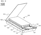
- FIG. 1 is an exploded perspective view schematically showing a structure of a conventional pouch-shaped battery cell.
- a pouch-shaped battery cell 100 includes an electrode assembly 130, electrode tabs 131 and 132 extending from the electrode assembly 130, electrode leads 140 and 141 welded to the electrode tabs 131 and 132, respectively, and a battery casing 120 in which the electrode assembly 130 is mounted.
- the electrode assembly 130 is a power generating device including a positive electrode and a negative electrode sequentially stacked with a separator interposed therebetween, and may be configured to have a stack type structure or a stack/folding type structure.
- the electrode tabs 131 and 132 extend from electrode plates of the electrode assembly 130, respectively.
- the electrode leads 140 and 141 are electrically connected to the electrode tabs 131 and 132, respectively, which extend from the electrode plates of the electrode assembly 130, for example, by welding.
- the electrode leads 140 and 141 are partially exposed outward from the battery casing 120.
- an insulating film 150 is partially attached to upper and lower surfaces of each of the electrode leads 140 and 141 in order to improve sealing between the electrode leads 140 and 141 and the battery casing 120 while ensuring electrical insulation therebetween.
- the battery casing 120 includes a casing body 122 having a concave-shaped receiving part 123 in which the electrode assembly 130 is seated, and a cover 121 integrated with the casing body 122. In a state in which the electrode assembly 130 is accommodated in the receiving part 123, opposite sides 124 and upper end 125 of the casing body 122 and the cover 121 come into contact with each other and then are bonded to each other, whereby a battery is completed.
- the battery casing 120 is configured to have an aluminum laminate structure including an outer layer of resin, a barrier layer of metal, and a sealant layer of resin exhibiting a thermal bonding property.
- the cover 121 and the opposite sides 124 and the upper end 125 of the casing body 122 come into contact with each other and then are bonded to each other when heat and pressure are applied thereto such that the resin layers are thermally fused together, whereby sealed margin portions are formed. Since the same resin layers of upper and lower parts of the battery casing are in direct contact with each other, the opposite sides 124 of the casing body 122 are allowed to be uniformly sealed with the cover 121 by thermal fusion.
- the electrode leads 140 and 141 positioned at the upper end 125 of the casing body 122 while protruding outward from the battery casing 120.
- the cover 121 and the upper end 150 of the casing body 122 are thermally fused together in a state in which the insulation films are interposed therebetween.
- the receiving part of the battery casing constituting the pouch-shaped battery cell is generally manufactured by a deep drawing method.
- Deep drawing is a representative forming process of manufacturing a hollow container without a joint using a planar plate, in which a plate material placed on a surface of a die is compressed by a punch and subjected to plastic working.
- the deep drawing method has an advantage of high process efficiency because a final hollow casing may be manufactured from a plate material by a series of successive processes.
- the elongation percentage of a metal plate material differs in each portion depending on the shape of a mold, and thus when the elongation percentage of the metal plate material exceeds the allowable range of elongation percentage, edge cracks may occur. Accordingly, the shape able to be processed by the deep drawing method is limited.
- portions that remain unfused may be formed at positions where the electrode leads are positioned due to the thickness of the electrode leads.
- a battery casing is divided into a first casing and a second casing provided with a first receiving part and a second receiving part, respectively, the first and second receiving parts having different sizes or shapes.
- the inventors of the present application have found that it is not necessary to form a single receiving part into a complicated structure to correspond to the shape of an electrode assembly having a complicated structure, so that the battery casing is formed more easily, thereby eliminating or reducing defects that may occur in the forming of the battery casing.
- the battery casing is provided with electrode lead grooves having a downwardly recessed structure, whereby at positions of the electrode leads of the battery casing, the occurrence of portions that remain unfused due to the thickness of the electrode leads is suppressed and thus the safety of a battery cell is efficiently enhanced, thereby leading to the present invention.
- a battery cell including: an electrode assembly including a positive electrode, a negative electrode, and a separator interposed between the positive electrode and the negative electrode, with electrode tabs protruding from at least one side of outside peripheral portions of the electrode assembly; and a battery casing including a first casing and a second casing provided with a first receiving part and a second receiving part, respectively, the first and second receiving parts respectively accommodating the electrode assemblies and having different sizes or shapes, wherein in a state in which electrode leads connected to the electrode tabs protrude from outside peripheral portions of the first and second casings, the battery casing is sealed by thermal fusion along the outside peripheral portions of the first and second casings, wherein electrode lead grooves are provided at a portion of the outside peripheral portions of the first and second casings where the electrode leads protrude, the electrode lead grooves being recessed downwardly such that the electrode leads are seated therein.
- the battery casing is not particularly limited in its material or construction as long as it can exert the above described effect.
- the battery casing may be made of a laminate sheet including a metal layer and a resin layer, considering ease of forming of the receiving parts, ease of sealing by thermal fusion, weight reduction of the battery cell, etc.
- the battery casing may be configured such that the first and second casings are integrated into a single unit at a predetermined portion of the outside peripheral portions, the first and second casings being configured such that in a state in which the first and second casings are folded at the predetermined portion, remaining portions of the outside peripheral portions are sealed by thermal fusion, such that the first and second receiving parts accommodate the electrode assemblies, respectively.
- the first and second receiving parts which are different in size or shape from each other, are formed on a planar laminate sheet having a predetermined unit size, whereby the first and second casings integrated with each other at the predetermined portion of the outside peripheral portions are formed to constitute the battery casing.
- first and second casings are integrated into a single unit, so that structural stability of the battery casing can be further improved.
- the distance between the first and second receiving parts may be in a range of 1.0 to 2.0 millimeter and more specifically, may be in a range of 1.1 to 1.7 millimeters.
- the battery casing may be damaged or thinned due to elongation occurring at the predetermined portion of the outside peripheral portions where the first casing and the second casing are integrated with each other due to the material characteristics of the battery casing made of a laminate sheet, which may lead to a degradation in structural stability or safety.
- a sealing portion may be formed in an excessively large size in the process of thermal fusion to the outside peripheral portion of the battery casing and thus an additional process for removing an unnecessary portion of the sealing portion may be required or an overall size of the battery cell may be increased. Accordingly, a space for mounting a device to which the battery cell is applied may be limited.
- first and second casings may be configured as separate members, and all the outside peripheral portions may be sealed by thermal fusion.
- the first and second casing are provided with the first and second receiving parts, respectively, which are different in size or shape from each other, the first and second receiving parts may be more variously configured and may be selectively and easily adapted according to the size or shape of the electrode assembly.
- first receiving part or the second receiving part, or both the first receiving part and the second receiving part may include at least one inner peripheral surface having a tapered structure in which width becomes gradually narrower outwards in a vertical cross section.
- the first and second receiving parts can be adapted more easily without additionally forming receiving parts in response to such structures.
- the electrode lead grooves may be formed at the portion of the outside peripheral portions of the first casing, or the second casing, or each of the first and second casings.
- the battery casing may be provided with the electrode lead grooves formed downwardly at the outside peripheral portion of the battery casing where the electrode leads protrude such that the electrode leads are seated in the grooves. More specifically, the battery casing may be configured such that the electrode lead grooves are formed only at one portion of the outside peripheral portions of the first or second casing, or are formed at portions of the outside peripheral portions of the first and second casings, respectively, which correspond to each other.
- the electrode lead grooves may be formed at the portion of the outside peripheral portions of each of the first casing and the second casing, and a total depth obtained by adding a depth of the electrode lead grooves formed at the first casing and a depth of the electrode lead grooves formed at the second casing may be smaller than thickness of the electrode leads.
- the electrode lead grooves are formed at the portion of the outside peripheral portions of each of the first and second casings, so that the electrode lead grooves can be recessed to have a lower depth than in the case where the electrode lead grooves are formed only at one portion of the outside peripheral portions of the battery casing.
- damage or defects that may occur in the outside peripheral portions of the battery casing can be efficiently prevented.
- the total depth obtained by adding the depth of the electrode lead grooves formed at the first casing and the depth of the electrode lead grooves formed at the second casing is relatively small compared to the thickness of the electrode leads, whereby when the battery casing is sealed by thermal fusion, the outside peripheral portions thereof are properly elongated and thus an aesthetic and smooth appearance can be presented.
- the total depth obtained by adding the depth of the electrode lead grooves formed at the first casing and the depth of the electrode lead grooves formed at the second casing may be 50 to 99% with respect to the thickness of the electrode leads.
- the effect through provision of the electrode lead grooves may not be obtained.
- the portions where the electrode lead grooves are formed may overlap each other and may be wrinkled, leading to the occurrence of poor appearance. Accordingly, when a sealing portion formed by the thermal fusion is additionally subjected to a process such as bending, the sealing portion may not be easily deformed.
- the depth of the electrode lead grooves formed at the first casing and the depth of the electrode lead grooves formed at the second casing may be equal to each other.
- the electrode assembly may include: a first unit cell having a structure corresponding to an inside shape of the first receiving part; and a second unit cell having a structure corresponding to an inside shape of the second receiving part.
- the electrode assembly may be composed of a combination of the first and second unit cells that are different in size or shape from each other, corresponding to the inside shapes of the first and second receiving parts, respectively.
- the first and second unit cells may not be particularly limited in structure as long as they can be easily formed into structures corresponding to the inside shapes of the first and second receiving parts, respectively.
- At least one unit cell of the first and second unit cells may be configured such that a positive electrode plate and a negative electrode plate are stacked with a separator interposed therebetween.
- the first unit cell, or the second unit cell, or both the first and second unit cells may be configured to have a stack type structure in which a positive electrode plate and a negative electrode plate are stacked with a separator interposed therebetween.
- At least one of the first and second unit cells may be configured such that a positive electrode sheet and a negative electrode sheet are wound with a separator sheet interposed therebetween in one direction.
- the first unit cell, or the second unit cell, or both the first and second unit cells may have a winding type structure in which a positive electrode sheet, a separator sheet, and a negative electrode sheet, which are formed in a long sheet shape, are simultaneously wound in one direction.
- At least one of the first and second unit cells may be configured such that a plurality of basic units each including a positive electrode plate, a negative electrode plate, and a separator interposed between the positive electrode plate and the negative electrode plate are wound using a separator sheet interposed between each of the basic units.
- the first unit cell, or the second unit cell, or both the first and second unit cells may be configured to have a stack/folding type structure in which the basic units each including a positive electrode plate, a negative electrode plate, and a separator interposed between the positive electrode plate and the negative electrode plate are arranged on a long-sheet shaped separator sheet and then simultaneously wound in one direction, such that the separator sheet is interposed between each of the basic units.
- the first and second unit cells may be configured such that a plurality of basic units of both the first and second unit cells are simultaneously wound using a single separator sheet interposed between each of the basic units, each of the basic units including a positive electrode plate, a negative electrode plate, and a separator interposed between the positive electrode plate and the negative electrode plate.
- the first and second unit cells may have a structure in which the single separator sheet is interposed between each of the basic units, such that the basic units of the first and second unit cells are simultaneously wound using the separator sheet to be connected to each other.
- the battery casing is divided into the first casing and the second casing provided with the first receiving part and the second receiving part, respectively, the first and second receiving parts having different sizes or shapes.
- the battery casing is provided with the electrode lead grooves having a downwardly recessed structure, whereby at positions of the electrode leads of the battery casing, the occurrence of portions that remain unfused due to the thickness of the electrode leads can be suppressed and thus the safety of the battery cell can be efficiently enhanced.
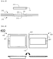
- FIG. 2 is a schematic view showing a structure of a battery casing of a battery cell according to an embodiment of the present invention
- FIG. 3 is an enlarged schematic front view showing electrode lead grooves of the battery casing of FIG. 2 .
- a battery casing 200 includes a first casing 210 and a second casing 220.
- the first and second casings 210 and 220 are integrated into a single unit at a predetermined portion 202 of outside peripheral portions, which is opposite to outside peripheral portions 201 and 201' where electrode tabs protrude, respectively.
- the first casing 210 and the second casing 220 includes a first receiving part 211 and a second receiving part 221, respectively, the first and second receiving parts 211 and 221 being recessed downwardly and in which electrode assemblies are accommodated, respectively.
- the first and second receiving parts 211 and 221 are formed in a rectangular parallelepiped shape, and configured such that lengths L1 and L2, which are corresponding to directions in which the electrode tabs protrude, are the same, while widths W1 and W2 and depths D1 and D2, which are perpendicular to the directions in which the electrode tabs protrude, are different from each other, respectively. More specifically, the width W1 and the depth D1 of the first receiving part 211 are relatively greater than the width W2 and the depth D2 of the second receiving part 221.
- the first and second casings 210 and 220 are folded at the predetermined portion 202 of the outside peripheral portions where the first and second casings 210 and 220 are integrated with each other, and then the remaining outside peripheral portions are thermal fused together, whereby the first and second casings 210 and 220 are sealed.
- the electrode assemblies are accommodated in the receiving parts 211 and 221, respectively.
- a distance L3 between the first and second receiving parts 211 and 221 at the predetermined portion 202 of the outside peripheral portions where the first and second casings 210 and 220 are integrated with each other may be formed in a range of 1.0 to 2.0 millimeters, such that in the process of forming the receiving parts 211 and 221 by deep drawing, damages to the predetermined portion 202 where the first and second casings 210 and 220 are integrated with each other can be prevented while formation of unnecessary sealing portions can be minimized. More specifically, the distance L3 may be in a range of 1.1 to 1.7 millimeters.
- the first and second casings 210 and 220 are provided with electrode lead grooves 212 and 222, respectively, the electrode lead grooves 212 and 222 being formed on the outside peripheral portions 201 and 201' where electrode leads 310 connected to the electrode taps protrude, respectively.
- the electrode lead grooves 212 and 222 are recessed downwardly such that the electrode leads 310 are seated therein, and the electrode lead grooves 212 and 222 are configured to communicate with the first receiving part 211 of the first casing 210 and the second receiving part 221 of the second casing 220.
- the depths of the electrode lead grooves 212 and 222 are equal to each other, and a total depth D3 obtained by adding the depths of the electrode lead grooves 212 and 222 is about 50% with respect to a thickness T1 of the electrode leads 310.
- the electrode lead grooves 212 and 222 can exhibit proper elongation whereby the finished appearance of the battery casing 200 is allowed to present an aesthetic and smooth appearance.
- FIGS. 4 and 5 are schematic views showing a structure of a battery casing of a battery cell according to further embodiments of the present invention.
- a battery casing 400 includes a first casing 410 and a second casing 420.
- the first casing 410 and the second casing 420 are configured as separate members structured such that second outside peripheral portions 402 and 402' opposite to first outside peripheral portions 401 and 401' where electrode tabs protrude, respectively, are separated from each other.
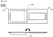
- a battery casing 500 includes a first casing 510 and a second casing 520.
- the first casing 510 includes an inner peripheral surface 513 inclindely formed at a position adjacent to a predetermined portion 502 of outside peripheral portions where first and second casings 510 and 520 are integrated with each other.
Landscapes
- Chemical & Material Sciences (AREA)
- Chemical Kinetics & Catalysis (AREA)
- Electrochemistry (AREA)
- General Chemical & Material Sciences (AREA)
- Inorganic Chemistry (AREA)
- Engineering & Computer Science (AREA)
- Manufacturing & Machinery (AREA)
- Sealing Battery Cases Or Jackets (AREA)
Abstract
Description
- The present invention relates to a battery cell having a battery casing with a receiving part and an electrode lead groove.
- In recent years, as the costs of energy sources have increased due to depletion of fossil fuels and interest in environmental pollution has become more intense, the demand for environmentally-friendly alternative energy sources has become an inevitable factor for the future. Thus, studies on techniques for generating electric power, such as nuclear energy, solar energy, wind energy, tidal energy, etc., continue to be conducted, and electric power storage devices for more efficient use of such generated energy are also attracting much attention.
- In particular, as techniques associated with mobile devices continue to develop and the demand therefor continues to increase, the demand for batteries as energy sources is rapidly increasing. Accordingly, various studies are being conducted on batteries that can meet various demands.
- In terms of the shape of batteries, there is a high demand for prismatic secondary batteries or pouch-shaped secondary batteries, which are thin enough to be applied to products such as mobile phones. In terms of the material for batteries, on the other hand, there is a high demand for lithium secondary batteries such as lithium ion batteries and lithium ion polymer batteries, which exhibit high energy density, discharge voltage, and output stability.
-
FIG. 1 is an exploded perspective view schematically showing a structure of a conventional pouch-shaped battery cell. - Referring to
FIG. 1 , a pouch-shaped battery cell 100 includes anelectrode assembly 130,electrode tabs electrode assembly 130, electrode leads 140 and 141 welded to theelectrode tabs battery casing 120 in which theelectrode assembly 130 is mounted. - The
electrode assembly 130 is a power generating device including a positive electrode and a negative electrode sequentially stacked with a separator interposed therebetween, and may be configured to have a stack type structure or a stack/folding type structure. Theelectrode tabs electrode assembly 130, respectively. The electrode leads 140 and 141 are electrically connected to theelectrode tabs electrode assembly 130, for example, by welding. The electrode leads 140 and 141 are partially exposed outward from thebattery casing 120. In addition, aninsulating film 150 is partially attached to upper and lower surfaces of each of the electrode leads 140 and 141 in order to improve sealing between the electrode leads 140 and 141 and thebattery casing 120 while ensuring electrical insulation therebetween. - The
battery casing 120 includes acasing body 122 having a concave-shaped receivingpart 123 in which theelectrode assembly 130 is seated, and acover 121 integrated with thecasing body 122. In a state in which theelectrode assembly 130 is accommodated in thereceiving part 123,opposite sides 124 andupper end 125 of thecasing body 122 and thecover 121 come into contact with each other and then are bonded to each other, whereby a battery is completed. Thebattery casing 120 is configured to have an aluminum laminate structure including an outer layer of resin, a barrier layer of metal, and a sealant layer of resin exhibiting a thermal bonding property. Thus, thecover 121 and theopposite sides 124 and theupper end 125 of thecasing body 122 come into contact with each other and then are bonded to each other when heat and pressure are applied thereto such that the resin layers are thermally fused together, whereby sealed margin portions are formed. Since the same resin layers of upper and lower parts of the battery casing are in direct contact with each other, theopposite sides 124 of thecasing body 122 are allowed to be uniformly sealed with thecover 121 by thermal fusion. On the other hand, the electrode leads 140 and 141 positioned at theupper end 125 of thecasing body 122 while protruding outward from thebattery casing 120. For this reason, in order to enhance sealing of thebattery casing 120 in consideration of the thickness of the electrode leads 140 and 141 and the difference in material between the electrode leads 140 and 141 and thebattery casing 120, thecover 121 and theupper end 150 of thecasing body 122 are thermally fused together in a state in which the insulation films are interposed therebetween. - In order to maximize the capacity of the secondary batteries by making maximum use of a battery cell mounting space in a device having various structures and sizes, studies on battery cells including a plurality of unit cells having different sizes have been actively conducted.
- In this regard, the receiving part of the battery casing constituting the pouch-shaped battery cell is generally manufactured by a deep drawing method. Deep drawing is a representative forming process of manufacturing a hollow container without a joint using a planar plate, in which a plate material placed on a surface of a die is compressed by a punch and subjected to plastic working.
- The deep drawing method has an advantage of high process efficiency because a final hollow casing may be manufactured from a plate material by a series of successive processes. However, the elongation percentage of a metal plate material differs in each portion depending on the shape of a mold, and thus when the elongation percentage of the metal plate material exceeds the allowable range of elongation percentage, edge cracks may occur. Accordingly, the shape able to be processed by the deep drawing method is limited.
- In particular, when forming the receiving part having a complicated structure corresponding to the shapes of the plurality of unit cells, such problems may be exacerbated due to the material characteristics of the pouch-shaped battery casing.
- In addition, even when the pouch-shaped battery casing is subjected to thermal fusion while the insulating films are interposed between the electrode leads, portions that remain unfused may be formed at positions where the electrode leads are positioned due to the thickness of the electrode leads.
- Consequently, sealing of the battery casing may be degraded at positions of the electrode leads. Moreover, in the case that swelling of the battery cell occurs due to gas generated by reactions between electrodes and electrolyte, pressure of the gas may be concentrated on the unfused portions formed at positions of the electrode leads, leading to damages to the battery casing and degradation in safety.
- Thus, there is a high demand for a technique for fundamentally solving these problems.
- The foregoing is intended merely to aid in the understanding of the background of the present invention, and is not intended to mean that the present invention falls within the purview of the related art that is already known to those skilled in the art.
- Accordingly, the present invention has been made keeping in mind the above problems occurring in the related art.
- The present inventors of the present application have carried out intensive research and various experiments. As described later, a battery casing is divided into a first casing and a second casing provided with a first receiving part and a second receiving part, respectively, the first and second receiving parts having different sizes or shapes. Thus, the inventors of the present application have found that it is not necessary to form a single receiving part into a complicated structure to correspond to the shape of an electrode assembly having a complicated structure, so that the battery casing is formed more easily, thereby eliminating or reducing defects that may occur in the forming of the battery casing. In addition, the battery casing is provided with electrode lead grooves having a downwardly recessed structure, whereby at positions of the electrode leads of the battery casing, the occurrence of portions that remain unfused due to the thickness of the electrode leads is suppressed and thus the safety of a battery cell is efficiently enhanced, thereby leading to the present invention.
- In order to achieve the above object, according to one aspect of the present invention, there is provided a battery cell, including: an electrode assembly including a positive electrode, a negative electrode, and a separator interposed between the positive electrode and the negative electrode, with electrode tabs protruding from at least one side of outside peripheral portions of the electrode assembly; and a battery casing including a first casing and a second casing provided with a first receiving part and a second receiving part, respectively, the first and second receiving parts respectively accommodating the electrode assemblies and having different sizes or shapes, wherein in a state in which electrode leads connected to the electrode tabs protrude from outside peripheral portions of the first and second casings, the battery casing is sealed by thermal fusion along the outside peripheral portions of the first and second casings, wherein electrode lead grooves are provided at a portion of the outside peripheral portions of the first and second casings where the electrode leads protrude, the electrode lead grooves being recessed downwardly such that the electrode leads are seated therein.
- Thus, it is not necessary to form a single receiving part into a complicated structure corresponding to the shape of the electrode assembly having a complicated structure, so that the battery casing can be formed more easily, thereby eliminating or reducing defects that may occur in the forming of the battery casing. In addition, due to provision of the electrode lead grooves, at positions of the electrode leads of the battery casing, the occurrence of portions that remain unfused due to the thickness of the electrode leads can be suppressed and thus the safety of a battery cell can be efficiently enhanced.
- In one specific example, the battery casing is not particularly limited in its material or construction as long as it can exert the above described effect. Specifically, the battery casing may be made of a laminate sheet including a metal layer and a resin layer, considering ease of forming of the receiving parts, ease of sealing by thermal fusion, weight reduction of the battery cell, etc.
- Further, the battery casing may be configured such that the first and second casings are integrated into a single unit at a predetermined portion of the outside peripheral portions, the first and second casings being configured such that in a state in which the first and second casings are folded at the predetermined portion, remaining portions of the outside peripheral portions are sealed by thermal fusion, such that the first and second receiving parts accommodate the electrode assemblies, respectively.
- In other words, the first and second receiving parts, which are different in size or shape from each other, are formed on a planar laminate sheet having a predetermined unit size, whereby the first and second casings integrated with each other at the predetermined portion of the outside peripheral portions are formed to constitute the battery casing.
- Thus, a forming process of the laminate sheet, which is required to separately form the first and second casings, can be partially omitted, so that time required for manufacturing the battery casing can be saved. In addition, the first and second casings are integrated into a single unit, so that structural stability of the battery casing can be further improved.
- In this case, at the predetermined portion of the outside peripheral portions where the first and second casings are integrated into a single unit, the distance between the first and second receiving parts may be in a range of 1.0 to 2.0 millimeter and more specifically, may be in a range of 1.1 to 1.7 millimeters.
- In the case that at the predetermined portion of the outside peripheral portions where the first and second casings are integrated into a single unit, the distance between the first and second receiving parts is excessively narrow outside the ranges, thus in the process of forming the first and second receiving parts by a deep drawing method, the battery casing may be damaged or thinned due to elongation occurring at the predetermined portion of the outside peripheral portions where the first casing and the second casing are integrated with each other due to the material characteristics of the battery casing made of a laminate sheet, which may lead to a degradation in structural stability or safety.
- On the other hand, in the case that at the predetermined portion of the outside peripheral portions where the first and second casings are integrated into a single unit, the distance between the first and second receiving parts is excessively wide outside the ranges, thus a sealing portion may be formed in an excessively large size in the process of thermal fusion to the outside peripheral portion of the battery casing and thus an additional process for removing an unnecessary portion of the sealing portion may be required or an overall size of the battery cell may be increased. Accordingly, a space for mounting a device to which the battery cell is applied may be limited.
- Meanwhile, the first and second casings may be configured as separate members, and all the outside peripheral portions may be sealed by thermal fusion.
- Accordingly, since the first and second casing are provided with the first and second receiving parts, respectively, which are different in size or shape from each other, the first and second receiving parts may be more variously configured and may be selectively and easily adapted according to the size or shape of the electrode assembly.
- Further, the first receiving part, or the second receiving part, or both the first receiving part and the second receiving part may include at least one inner peripheral surface having a tapered structure in which width becomes gradually narrower outwards in a vertical cross section.
- Thus, even when the electrode assembly accommodated in the first receiving part or the second receiving part further includes an irregular structure such as a step-like structure or an inclined structure, the first and second receiving parts can be adapted more easily without additionally forming receiving parts in response to such structures.
- In one specific example, the electrode lead grooves may be formed at the portion of the outside peripheral portions of the first casing, or the second casing, or each of the first and second casings.
- As described above, the battery casing may be provided with the electrode lead grooves formed downwardly at the outside peripheral portion of the battery casing where the electrode leads protrude such that the electrode leads are seated in the grooves. More specifically, the battery casing may be configured such that the electrode lead grooves are formed only at one portion of the outside peripheral portions of the first or second casing, or are formed at portions of the outside peripheral portions of the first and second casings, respectively, which correspond to each other.
- In this case, the electrode lead grooves may be formed at the portion of the outside peripheral portions of each of the first casing and the second casing, and a total depth obtained by adding a depth of the electrode lead grooves formed at the first casing and a depth of the electrode lead grooves formed at the second casing may be smaller than thickness of the electrode leads.
- More specifically, the electrode lead grooves are formed at the portion of the outside peripheral portions of each of the first and second casings, so that the electrode lead grooves can be recessed to have a lower depth than in the case where the electrode lead grooves are formed only at one portion of the outside peripheral portions of the battery casing. Thus, in the process of forming the electrode lead grooves through a deep drawing method, damage or defects that may occur in the outside peripheral portions of the battery casing can be efficiently prevented.
- In addition, the total depth obtained by adding the depth of the electrode lead grooves formed at the first casing and the depth of the electrode lead grooves formed at the second casing is relatively small compared to the thickness of the electrode leads, whereby when the battery casing is sealed by thermal fusion, the outside peripheral portions thereof are properly elongated and thus an aesthetic and smooth appearance can be presented.
- More specifically, the total depth obtained by adding the depth of the electrode lead grooves formed at the first casing and the depth of the electrode lead grooves formed at the second casing may be 50 to 99% with respect to the thickness of the electrode leads.
- In the case that obtained by adding the depth of the electrode lead grooves formed at the first casing and the depth of the electrode lead grooves formed at the second casing is less than 50% with respect to the thickness of the electrode leads, the effect through provision of the electrode lead grooves may not be obtained.
- On the other hand, in the case that obtained by adding the depth of the electrode lead grooves formed at the first casing and the depth of the electrode lead grooves formed at the second casing exceeds 99% with respect to the thickness of the electrode leads, in the process of thermal fusion of the outside peripheral portions of the battery casing, the portions where the electrode lead grooves are formed may overlap each other and may be wrinkled, leading to the occurrence of poor appearance. Accordingly, when a sealing portion formed by the thermal fusion is additionally subjected to a process such as bending, the sealing portion may not be easily deformed.
- Meanwhile, the depth of the electrode lead grooves formed at the first casing and the depth of the electrode lead grooves formed at the second casing may be equal to each other.
- Thus, in the process of thermal fusion of the outside peripheral portions of the battery casing, conditions such as temperature, pressure, etc. applied to the electrode lead grooves formed at each of the first and second casings can be more easily adjusted. In addition, the deformation ratios of the outside peripheral portions of the battery casing due to the thermal fusion are similar or almost the same, whereby the outer circumferential surface of the sealing portion of the outside peripheral portions can present a more smooth appearance.
- In one specific example, the electrode assembly may include: a first unit cell having a structure corresponding to an inside shape of the first receiving part; and a second unit cell having a structure corresponding to an inside shape of the second receiving part.
- In other words, the electrode assembly may be composed of a combination of the first and second unit cells that are different in size or shape from each other, corresponding to the inside shapes of the first and second receiving parts, respectively.
- In this case, the first and second unit cells may not be particularly limited in structure as long as they can be easily formed into structures corresponding to the inside shapes of the first and second receiving parts, respectively.
- In one specific example, at least one unit cell of the first and second unit cells may be configured such that a positive electrode plate and a negative electrode plate are stacked with a separator interposed therebetween.
- In other words, the first unit cell, or the second unit cell, or both the first and second unit cells may be configured to have a stack type structure in which a positive electrode plate and a negative electrode plate are stacked with a separator interposed therebetween.
- In another specific example, at least one of the first and second unit cells may be configured such that a positive electrode sheet and a negative electrode sheet are wound with a separator sheet interposed therebetween in one direction.
- In other words, the first unit cell, or the second unit cell, or both the first and second unit cells may have a winding type structure in which a positive electrode sheet, a separator sheet, and a negative electrode sheet, which are formed in a long sheet shape, are simultaneously wound in one direction.
- In a further specific example, at least one of the first and second unit cells may be configured such that a plurality of basic units each including a positive electrode plate, a negative electrode plate, and a separator interposed between the positive electrode plate and the negative electrode plate are wound using a separator sheet interposed between each of the basic units.
- In other words, the first unit cell, or the second unit cell, or both the first and second unit cells may be configured to have a stack/folding type structure in which the basic units each including a positive electrode plate, a negative electrode plate, and a separator interposed between the positive electrode plate and the negative electrode plate are arranged on a long-sheet shaped separator sheet and then simultaneously wound in one direction, such that the separator sheet is interposed between each of the basic units.
- In yet another specific example, the first and second unit cells may be configured such that a plurality of basic units of both the first and second unit cells are simultaneously wound using a single separator sheet interposed between each of the basic units, each of the basic units including a positive electrode plate, a negative electrode plate, and a separator interposed between the positive electrode plate and the negative electrode plate.
- In other words, the first and second unit cells may have a structure in which the single separator sheet is interposed between each of the basic units, such that the basic units of the first and second unit cells are simultaneously wound using the separator sheet to be connected to each other.
- The remaining configurations of the battery cell except for the above configuration and structure are well known in the art, so a detailed description thereof will be omitted herein.
- As described above, in the present invention, the battery casing is divided into the first casing and the second casing provided with the first receiving part and the second receiving part, respectively, the first and second receiving parts having different sizes or shapes. Thus, it is not necessary to form a single receiving part into a complicated structure to correspond to the shape of an electrode assembly having a complicated structure, so that the battery casing can be formed more easily, thereby eliminating or reducing defects that may occur in the forming of the battery casing. In addition, the battery casing is provided with the electrode lead grooves having a downwardly recessed structure, whereby at positions of the electrode leads of the battery casing, the occurrence of portions that remain unfused due to the thickness of the electrode leads can be suppressed and thus the safety of the battery cell can be efficiently enhanced.
- The above and other objects, features and other advantages of the present invention will be more clearly understood from the following detailed description when taken in conjunction with the accompanying drawings, in which:
-
FIG. 1 is an exploded perspective view schematically showing a structure of a conventional pouch-shaped battery cell; -
FIG. 2 is a schematic view showing a structure of a battery casing of a battery cell according to an embodiment of the present invention; -
FIG. 3 is an enlarged schematic front view showing electrode lead grooves of the battery casing ofFIG. 2 ; and -
FIGS. 4 and5 are schematic views showing a structure of a battery casing of a battery cell according to further embodiments of the present invention. - Hereinbelow, exemplary embodiments of the present invention will be described in detail with reference to the accompanying drawings. Various changes to the following embodiments are possible and the scope of the present invention is not limited to the following embodiments.
-
FIG. 2 is a schematic view showing a structure of a battery casing of a battery cell according to an embodiment of the present invention, andFIG. 3 is an enlarged schematic front view showing electrode lead grooves of the battery casing ofFIG. 2 . - Referring to
FIGS. 2 and3 , a battery casing 200 includes afirst casing 210 and asecond casing 220. The first andsecond casings predetermined portion 202 of outside peripheral portions, which is opposite to outsideperipheral portions 201 and 201' where electrode tabs protrude, respectively. - The
first casing 210 and thesecond casing 220 includes a first receivingpart 211 and asecond receiving part 221, respectively, the first and second receivingparts - The first and second receiving
parts part 211 are relatively greater than the width W2 and the depth D2 of the second receivingpart 221. - The first and
second casings predetermined portion 202 of the outside peripheral portions where the first andsecond casings second casings parts - A distance L3 between the first and second receiving
parts predetermined portion 202 of the outside peripheral portions where the first andsecond casings parts predetermined portion 202 where the first andsecond casings - The first and
second casings electrode lead grooves electrode lead grooves peripheral portions 201 and 201' where electrode leads 310 connected to the electrode taps protrude, respectively. - The
electrode lead grooves electrode lead grooves part 211 of thefirst casing 210 and the second receivingpart 221 of thesecond casing 220. - The depths of the
electrode lead grooves electrode lead grooves - Thus, when the outside
peripheral portions 201 and 202' of the battery casing 200 where the electrode leads 310 protrude are thermally fused together, the portions that remain unfused due to the thickness T1 of the electrode leads 310 can be suppressed from being generated. In addition, theelectrode lead grooves -
FIGS. 4 and5 are schematic views showing a structure of a battery casing of a battery cell according to further embodiments of the present invention. - First, referring to
FIG. 4 , abattery casing 400 includes afirst casing 410 and asecond casing 420. Thefirst casing 410 and thesecond casing 420 are configured as separate members structured such that second outsideperipheral portions 402 and 402' opposite to first outsideperipheral portions 401 and 401' where electrode tabs protrude, respectively, are separated from each other. - The remaining configurations except for the above configuration are the same as those of the battery casing of
FIG. 2 , so a detailed description thereof will be omitted. - Referring to
FIG. 5 , abattery casing 500 includes afirst casing 510 and asecond casing 520. Thefirst casing 510 includes an innerperipheral surface 513 inclindely formed at a position adjacent to apredetermined portion 502 of outside peripheral portions where first andsecond casings - The remaining configurations except for the above configuration are the same as those of the battery casing of
FIG. 2 , so a detailed description thereof will be omitted. - Although a preferred embodiment of the present invention has been described for illustrative purposes, those skilled in the art will appreciate that various modifications, additions and substitutions are possible, without departing from the scope and spirit of the invention as disclosed in the accompanying claims.
Claims (15)
- A battery cell, comprising:an electrode assembly including a positive electrode, a negative electrode, and a separator interposed between the positive electrode and the negative electrode, with electrode tabs protruding from at least one side of outside peripheral portions of the electrode assembly; anda battery casing including a first casing and a second casing provided with a first receiving part and a second receiving part, respectively, the first and second receiving parts respectively accommodating the electrode assemblies and having different sizes or shapes, wherein in a state in which electrode leads connected to the electrode tabs protrude from outside peripheral portions of the first and second casings, the battery casing is sealed by thermal fusion along the outside peripheral portions of the first and second casings,wherein electrode lead grooves are provided at a portion of the outside peripheral portions of the first and second casings where the electrode leads protrude, the electrode lead grooves being recessed downwardly such that the electrode leads are seated therein.
- The battery cell of claim 1, wherein the battery casing is made of a laminate sheet including a metal layer and a resin layer.
- The battery cell of claim 1, wherein the battery casing in configured such that the first and second casings are integrated into a single unit at a predetermined portion of the outside peripheral portions, the first and second casings being configured such that in a state in which the first and second casings are folded at the predetermined portion, remaining portions of the outside peripheral portions are sealed by thermal fusion, such that the first and second receiving parts accommodate the electrode assemblies, respectively.
- The battery cell of claim 3, wherein at the predetermined portion where the first and second casings are integrated into the single unit, a distance between the first and second receiving parts is in a range of 1.0 to 2.0 millimeters.
- The battery cell of claim 1, wherein the first and second casings are configured as separated members, and all the outside peripheral portions are sealed by thermal fusion.
- The battery cell of claim 1, wherein the first receiving part, or the second receiving part, or both the first receiving part and the second receiving part include at least one inner peripheral surface having a tapered structure in which width becomes gradually narrower outwards in a vertical cross section.
- The battery cell of claim 1, wherein the electrode lead grooves are formed at the portion of the outside peripheral portions of the first casing, or the second casing, or each of the first and second casings.
- The battery cell of claim 7, wherein the electrode lead grooves are formed at the portion of the outside peripheral portions of each of the first casing and the second casing; and
a total depth obtained by adding a depth of the electrode lead grooves formed at the first casing and a depth of the electrode lead grooves formed at the second casing is smaller than thickness of the electrode leads. - The battery cell of claim 8, wherein the total depth obtained by adding the depth of the electrode lead grooves formed at the first casing and the depth of the electrode lead grooves formed the second casing is 50 to 99% with respect to the thickness of the electrode leads.
- The battery cell of claim 8, wherein the depth of the electrode lead grooves formed at the first casing and the depth of the electrode lead grooves formed at the second casing are equal to each other.
- The battery cell of claim 1, wherein the electrode assembly includes:a first unit cell having a structure corresponding to an inside shape of the first receiving part; anda second unit cell having a structure corresponding to an inside shape of the second receiving part.
- The battery cell of claim 11, wherein at least one of the first and second unit cells is configured such that a positive electrode plate and a negative electrode plate are stacked with a separator interposed therebetween.
- The battery cell of claim 11, wherein at least one of the first and second unit cells is configured such that a positive electrode sheet and a negative electrode sheet are wound with a separator sheet interposed therebetween in one direction.
- The battery cell of claim 11, wherein at least one of the first and second unit cells is configured such that a plurality of basic units each including a positive electrode plate, a negative electrode plate, and a separator interposed between the positive electrode plate and the negative electrode plate are wound using a separator sheet interposed between each of the basic units.
- The battery cell of claim 11, wherein the first and second unit cells are configured such that a plurality of basic units of both the first and second unit cells are simultaneously wound using a single separator sheet interposed between each of the basic units, each of the basic units including a positive electrode plate, a negative electrode plate, and a separator interposed between the positive electrode plate and the negative electrode plate.
Applications Claiming Priority (2)
| Application Number | Priority Date | Filing Date | Title |
|---|---|---|---|
| KR1020160124699A KR20180034903A (en) | 2016-09-28 | 2016-09-28 | Battery Cell Comprising Battery Case Having Receiving Part and Groove for Electrode Lead |
| PCT/KR2017/010841 WO2018062902A1 (en) | 2016-09-28 | 2017-09-28 | Battery cell comprising battery case including accommodation part and electrode lead groove |
Publications (3)
| Publication Number | Publication Date |
|---|---|
| EP3399569A1 true EP3399569A1 (en) | 2018-11-07 |
| EP3399569A4 EP3399569A4 (en) | 2019-03-06 |
| EP3399569B1 EP3399569B1 (en) | 2024-12-25 |
Family
ID=61763505
Family Applications (1)
| Application Number | Title | Priority Date | Filing Date |
|---|---|---|---|
| EP17856788.9A Active EP3399569B1 (en) | 2016-09-28 | 2017-09-28 | Battery cell comprising battery case including accommodation part and electrode lead groove |
Country Status (8)
| Country | Link |
|---|---|
| US (1) | US11855296B2 (en) |
| EP (1) | EP3399569B1 (en) |
| KR (1) | KR20180034903A (en) |
| CN (1) | CN108780857B (en) |
| ES (1) | ES3005782T3 (en) |
| HU (1) | HUE069930T2 (en) |
| PL (1) | PL3399569T3 (en) |
| WO (1) | WO2018062902A1 (en) |
Cited By (1)
| Publication number | Priority date | Publication date | Assignee | Title |
|---|---|---|---|---|
| EP4164038A4 (en) * | 2020-07-02 | 2023-09-20 | Ningde Amperex Technology Limited | ELECTROCHEMICAL DEVICE AND ELECTRICAL DEVICE |
Families Citing this family (3)
| Publication number | Priority date | Publication date | Assignee | Title |
|---|---|---|---|---|
| KR102826600B1 (en) * | 2020-07-14 | 2025-06-27 | 에스케이온 주식회사 | Pouch case for secondary battery, Pouch type Secondary Battery, Secondary Battery Module and Manufacturing method of the secondary battery |
| CN115189079B (en) * | 2022-06-16 | 2023-10-03 | 万向一二三股份公司 | Method for optimizing wedge angle and shell distance of wedge-shaped end socket of flexible package power battery |
| KR20240079515A (en) * | 2022-11-29 | 2024-06-05 | 에스케이온 주식회사 | Pouch unit and battery cell including the same |
Family Cites Families (15)
| Publication number | Priority date | Publication date | Assignee | Title |
|---|---|---|---|---|
| KR20050020357A (en) | 2003-08-22 | 2005-03-04 | 삼성에스디아이 주식회사 | Pouch case and pouched type secondary battery comprising the same |
| KR100571269B1 (en) | 2004-09-22 | 2006-04-13 | 삼성에스디아이 주식회사 | Pouches for secondary batteries and pouch type secondary batteries |
| KR101170881B1 (en) * | 2007-11-17 | 2012-08-03 | 주식회사 엘지화학 | High Power Secondary Battery of Series Connection Structure |
| JP5793788B2 (en) | 2009-05-21 | 2015-10-14 | エルジー ケム. エルティーディ. | Water-resistant pouch-type secondary battery |
| KR101441530B1 (en) | 2011-06-09 | 2014-09-17 | 주식회사 엘지화학 | Battery Cell of Novel Structure And Battery Pack Employed with the Same |
| KR101940362B1 (en) * | 2012-02-29 | 2019-01-18 | 닛신 세이코 가부시키가이샤 | Exterior material for laminated battery, method for manufacturing exterior material for laminated battery, method for manufacturing laminated battery and laminated battery |
| KR101560563B1 (en) * | 2012-09-19 | 2015-10-16 | 주식회사 엘지화학 | Secondary Battery Of Improved Cooling Efficiency |
| KR20140100032A (en) * | 2013-02-05 | 2014-08-14 | 주식회사 엘지화학 | Battery Cell Having Structure of Steps-Formed |
| JP2014170459A (en) | 2013-03-05 | 2014-09-18 | Toshiba Corp | Electronic apparatus and heat dissipation device |
| WO2015147066A1 (en) * | 2014-03-25 | 2015-10-01 | 日本電気株式会社 | Multilayer battery and manufacturing method therefor |
| KR101725901B1 (en) | 2014-10-07 | 2017-04-11 | 주식회사 엘지화학 | Battery Cell Comprising Battery Case of Shape Corresponding to Electrode Assembly of Stair-like Structure |
| KR101794939B1 (en) * | 2014-11-26 | 2017-11-07 | 주식회사 엘지화학 | Battery Cell Comprising Electrode Assemblies of Different Size and Method for Preparing the Same |
| KR101793729B1 (en) | 2014-12-24 | 2017-11-03 | 주식회사 엘지화학 | Pouch type secondary battery and a method of making the same |
| KR102360413B1 (en) | 2015-02-16 | 2022-02-09 | 삼성에스디아이 주식회사 | Secondary Battery |
| KR20150133165A (en) | 2015-11-12 | 2015-11-27 | 주식회사 엘지화학 | Battery Cell Having Structure of Steps-Formed |
-
2016
- 2016-09-28 KR KR1020160124699A patent/KR20180034903A/en not_active Ceased
-
2017
- 2017-09-28 ES ES17856788T patent/ES3005782T3/en active Active
- 2017-09-28 PL PL17856788.9T patent/PL3399569T3/en unknown
- 2017-09-28 CN CN201780017120.4A patent/CN108780857B/en active Active
- 2017-09-28 WO PCT/KR2017/010841 patent/WO2018062902A1/en not_active Ceased
- 2017-09-28 HU HUE17856788A patent/HUE069930T2/en unknown
- 2017-09-28 EP EP17856788.9A patent/EP3399569B1/en active Active
- 2017-09-28 US US16/076,430 patent/US11855296B2/en active Active
Cited By (2)
| Publication number | Priority date | Publication date | Assignee | Title |
|---|---|---|---|---|
| EP4164038A4 (en) * | 2020-07-02 | 2023-09-20 | Ningde Amperex Technology Limited | ELECTROCHEMICAL DEVICE AND ELECTRICAL DEVICE |
| US12573695B2 (en) | 2020-07-02 | 2026-03-10 | Ningde Amperex Technology Limited | Electrochemical device and electrical device |
Also Published As
| Publication number | Publication date |
|---|---|
| EP3399569B1 (en) | 2024-12-25 |
| EP3399569A4 (en) | 2019-03-06 |
| US20190044106A1 (en) | 2019-02-07 |
| PL3399569T3 (en) | 2025-03-10 |
| CN108780857B (en) | 2022-05-06 |
| CN108780857A (en) | 2018-11-09 |
| US11855296B2 (en) | 2023-12-26 |
| ES3005782T3 (en) | 2025-03-17 |
| WO2018062902A1 (en) | 2018-04-05 |
| KR20180034903A (en) | 2018-04-05 |
| HUE069930T2 (en) | 2025-04-28 |
Similar Documents
| Publication | Publication Date | Title |
|---|---|---|
| US11935997B2 (en) | Pouch exterior for secondary battery, pouch-type secondary battery using the pouch exterior, and method of manufacturing the pouch-type secondary battery | |
| KR101402657B1 (en) | Battery Pack of Irregular Structure | |
| KR101596269B1 (en) | Battery Cell of Novel Structure | |
| US11050103B2 (en) | Pouch cell and method of forming same | |
| WO2019121332A1 (en) | Pouch cell and method of manufacturing same | |
| EP3399569B1 (en) | Battery cell comprising battery case including accommodation part and electrode lead groove | |
| KR102275545B1 (en) | Bettery cell and fabricating method of the same | |
| KR101786908B1 (en) | Battery Case Having Pattern For Anti-wrinkle | |
| EP3255722B1 (en) | Battery module having improved cooling structure | |
| KR20160041247A (en) | Battery Cell Comprising Battery Case of Shape Corresponding to Electrode Assembly of Stair-like Structure | |
| CN110993836A (en) | Battery module | |
| KR102238177B1 (en) | Battery cell and method of preparing electrode lead | |
| US12183933B2 (en) | Cylindrical battery and manufacturing method thereof | |
| KR102115624B1 (en) | Electric storage device | |
| KR101994842B1 (en) | Electrode Plate Having Structure Capable of Maximizing Interior Space Occupancy for Secondary Battery, and Secondary Battery or Capacitor Comprising the Same | |
| KR102576583B1 (en) | Bettery cell | |
| KR101867650B1 (en) | Battery Cell Employed with Battery Case Having Depressed Groove | |
| KR20210037460A (en) | The Battery Case For Secondary Battery And The Method For Manufacturing Thereof | |
| JP7035954B2 (en) | Battery module | |
| KR20170072487A (en) | Method Preparing Electrode Assembly Having Corner Cutting Structure and Electrode Assembly Prepared Using the Same | |
| WO2021144928A1 (en) | Power storage element and method for manufacturing same | |
| KR20230070964A (en) | Forming apparatus |
Legal Events
| Date | Code | Title | Description |
|---|---|---|---|
| STAA | Information on the status of an ep patent application or granted ep patent |
Free format text: STATUS: THE INTERNATIONAL PUBLICATION HAS BEEN MADE |
|
| PUAI | Public reference made under article 153(3) epc to a published international application that has entered the european phase |
Free format text: ORIGINAL CODE: 0009012 |
|
| STAA | Information on the status of an ep patent application or granted ep patent |
Free format text: STATUS: REQUEST FOR EXAMINATION WAS MADE |
|
| 17P | Request for examination filed |
Effective date: 20180801 |
|
| AK | Designated contracting states |
Kind code of ref document: A1 Designated state(s): AL AT BE BG CH CY CZ DE DK EE ES FI FR GB GR HR HU IE IS IT LI LT LU LV MC MK MT NL NO PL PT RO RS SE SI SK SM TR |
|
| AX | Request for extension of the european patent |
Extension state: BA ME |
|
| RIC1 | Information provided on ipc code assigned before grant |
Ipc: H01M 2/06 20060101AFI20190123BHEP Ipc: H01M 10/04 20060101ALI20190123BHEP Ipc: H01M 2/02 20060101ALI20190123BHEP |
|
| A4 | Supplementary search report drawn up and despatched |
Effective date: 20190131 |
|
| DAV | Request for validation of the european patent (deleted) | ||
| DAX | Request for extension of the european patent (deleted) | ||
| STAA | Information on the status of an ep patent application or granted ep patent |
Free format text: STATUS: EXAMINATION IS IN PROGRESS |
|
| 17Q | First examination report despatched |
Effective date: 20210604 |
|
| RAP1 | Party data changed (applicant data changed or rights of an application transferred) |
Owner name: LG ENERGY SOLUTION LTD. |
|
| RAP3 | Party data changed (applicant data changed or rights of an application transferred) |
Owner name: LG ENERGY SOLUTION, LTD. |
|
| REG | Reference to a national code |
Ref country code: DE Ref legal event code: R079 Free format text: PREVIOUS MAIN CLASS: H01M0002060000 Ipc: H01M0050124000 Ref country code: DE Ref legal event code: R079 Ref document number: 602017086993 Country of ref document: DE Free format text: PREVIOUS MAIN CLASS: H01M0002060000 Ipc: H01M0050124000 |
|
| GRAP | Despatch of communication of intention to grant a patent |
Free format text: ORIGINAL CODE: EPIDOSNIGR1 |
|
| STAA | Information on the status of an ep patent application or granted ep patent |
Free format text: STATUS: GRANT OF PATENT IS INTENDED |
|
| RIC1 | Information provided on ipc code assigned before grant |
Ipc: H01M 50/186 20210101ALI20240828BHEP Ipc: H01M 50/121 20210101ALI20240828BHEP Ipc: H01M 50/119 20210101ALI20240828BHEP Ipc: H01M 50/178 20210101ALI20240828BHEP Ipc: H01M 50/54 20210101ALI20240828BHEP Ipc: H01M 50/55 20210101ALI20240828BHEP Ipc: H01M 50/124 20210101AFI20240828BHEP |
|
| INTG | Intention to grant announced |
Effective date: 20240909 |
|
| GRAS | Grant fee paid |
Free format text: ORIGINAL CODE: EPIDOSNIGR3 |
|
| GRAA | (expected) grant |
Free format text: ORIGINAL CODE: 0009210 |
|
| STAA | Information on the status of an ep patent application or granted ep patent |
Free format text: STATUS: THE PATENT HAS BEEN GRANTED |
|
| P01 | Opt-out of the competence of the unified patent court (upc) registered |
Free format text: CASE NUMBER: APP_56914/2024 Effective date: 20241018 |
|
| AK | Designated contracting states |
Kind code of ref document: B1 Designated state(s): AL AT BE BG CH CY CZ DE DK EE ES FI FR GB GR HR HU IE IS IT LI LT LU LV MC MK MT NL NO PL PT RO RS SE SI SK SM TR |
|
| REG | Reference to a national code |
Ref country code: GB Ref legal event code: FG4D |
|
| REG | Reference to a national code |
Ref country code: CH Ref legal event code: EP |
|
| REG | Reference to a national code |
Ref country code: DE Ref legal event code: R096 Ref document number: 602017086993 Country of ref document: DE |
|
| REG | Reference to a national code |
Ref country code: IE Ref legal event code: FG4D |
|
| REG | Reference to a national code |
Ref country code: SE Ref legal event code: TRGR |
|
| REG | Reference to a national code |
Ref country code: ES Ref legal event code: FG2A Ref document number: 3005782 Country of ref document: ES Kind code of ref document: T3 Effective date: 20250317 |
|
| REG | Reference to a national code |
Ref country code: LT Ref legal event code: MG9D |
|
| PG25 | Lapsed in a contracting state [announced via postgrant information from national office to epo] |
Ref country code: FI Free format text: LAPSE BECAUSE OF FAILURE TO SUBMIT A TRANSLATION OF THE DESCRIPTION OR TO PAY THE FEE WITHIN THE PRESCRIBED TIME-LIMIT Effective date: 20241225 |
|
| PG25 | Lapsed in a contracting state [announced via postgrant information from national office to epo] |
Ref country code: BG Free format text: LAPSE BECAUSE OF FAILURE TO SUBMIT A TRANSLATION OF THE DESCRIPTION OR TO PAY THE FEE WITHIN THE PRESCRIBED TIME-LIMIT Effective date: 20241225 |
|
| PG25 | Lapsed in a contracting state [announced via postgrant information from national office to epo] |
Ref country code: NO Free format text: LAPSE BECAUSE OF FAILURE TO SUBMIT A TRANSLATION OF THE DESCRIPTION OR TO PAY THE FEE WITHIN THE PRESCRIBED TIME-LIMIT Effective date: 20250325 |
|
| PG25 | Lapsed in a contracting state [announced via postgrant information from national office to epo] |
Ref country code: GR Free format text: LAPSE BECAUSE OF FAILURE TO SUBMIT A TRANSLATION OF THE DESCRIPTION OR TO PAY THE FEE WITHIN THE PRESCRIBED TIME-LIMIT Effective date: 20250326 Ref country code: LV Free format text: LAPSE BECAUSE OF FAILURE TO SUBMIT A TRANSLATION OF THE DESCRIPTION OR TO PAY THE FEE WITHIN THE PRESCRIBED TIME-LIMIT Effective date: 20241225 |
|
| REG | Reference to a national code |
Ref country code: HU Ref legal event code: AG4A Ref document number: E069930 Country of ref document: HU |
|
| PG25 | Lapsed in a contracting state [announced via postgrant information from national office to epo] |
Ref country code: RS Free format text: LAPSE BECAUSE OF FAILURE TO SUBMIT A TRANSLATION OF THE DESCRIPTION OR TO PAY THE FEE WITHIN THE PRESCRIBED TIME-LIMIT Effective date: 20250325 |
|
| REG | Reference to a national code |
Ref country code: NL Ref legal event code: MP Effective date: 20241225 |
|
| PG25 | Lapsed in a contracting state [announced via postgrant information from national office to epo] |
Ref country code: NL Free format text: LAPSE BECAUSE OF FAILURE TO SUBMIT A TRANSLATION OF THE DESCRIPTION OR TO PAY THE FEE WITHIN THE PRESCRIBED TIME-LIMIT Effective date: 20241225 |
|
| REG | Reference to a national code |
Ref country code: AT Ref legal event code: MK05 Ref document number: 1754986 Country of ref document: AT Kind code of ref document: T Effective date: 20241225 |
|
| PG25 | Lapsed in a contracting state [announced via postgrant information from national office to epo] |
Ref country code: SM Free format text: LAPSE BECAUSE OF FAILURE TO SUBMIT A TRANSLATION OF THE DESCRIPTION OR TO PAY THE FEE WITHIN THE PRESCRIBED TIME-LIMIT Effective date: 20241225 |
|
| PG25 | Lapsed in a contracting state [announced via postgrant information from national office to epo] |
Ref country code: IS Free format text: LAPSE BECAUSE OF FAILURE TO SUBMIT A TRANSLATION OF THE DESCRIPTION OR TO PAY THE FEE WITHIN THE PRESCRIBED TIME-LIMIT Effective date: 20250425 |
|
| PG25 | Lapsed in a contracting state [announced via postgrant information from national office to epo] |
Ref country code: PT Free format text: LAPSE BECAUSE OF FAILURE TO SUBMIT A TRANSLATION OF THE DESCRIPTION OR TO PAY THE FEE WITHIN THE PRESCRIBED TIME-LIMIT Effective date: 20250428 |
|
| PG25 | Lapsed in a contracting state [announced via postgrant information from national office to epo] |
Ref country code: EE Free format text: LAPSE BECAUSE OF FAILURE TO SUBMIT A TRANSLATION OF THE DESCRIPTION OR TO PAY THE FEE WITHIN THE PRESCRIBED TIME-LIMIT Effective date: 20241225 |
|
| PG25 | Lapsed in a contracting state [announced via postgrant information from national office to epo] |
Ref country code: AT Free format text: LAPSE BECAUSE OF FAILURE TO SUBMIT A TRANSLATION OF THE DESCRIPTION OR TO PAY THE FEE WITHIN THE PRESCRIBED TIME-LIMIT Effective date: 20241225 Ref country code: RO Free format text: LAPSE BECAUSE OF FAILURE TO SUBMIT A TRANSLATION OF THE DESCRIPTION OR TO PAY THE FEE WITHIN THE PRESCRIBED TIME-LIMIT Effective date: 20241225 |
|
| PG25 | Lapsed in a contracting state [announced via postgrant information from national office to epo] |
Ref country code: SK Free format text: LAPSE BECAUSE OF FAILURE TO SUBMIT A TRANSLATION OF THE DESCRIPTION OR TO PAY THE FEE WITHIN THE PRESCRIBED TIME-LIMIT Effective date: 20241225 |
|
| PG25 | Lapsed in a contracting state [announced via postgrant information from national office to epo] |
Ref country code: CZ Free format text: LAPSE BECAUSE OF FAILURE TO SUBMIT A TRANSLATION OF THE DESCRIPTION OR TO PAY THE FEE WITHIN THE PRESCRIBED TIME-LIMIT Effective date: 20241225 |
|
| PG25 | Lapsed in a contracting state [announced via postgrant information from national office to epo] |
Ref country code: IT Free format text: LAPSE BECAUSE OF FAILURE TO SUBMIT A TRANSLATION OF THE DESCRIPTION OR TO PAY THE FEE WITHIN THE PRESCRIBED TIME-LIMIT Effective date: 20241225 |
|
| REG | Reference to a national code |
Ref country code: DE Ref legal event code: R097 Ref document number: 602017086993 Country of ref document: DE |
|
| PG25 | Lapsed in a contracting state [announced via postgrant information from national office to epo] |
Ref country code: DK Free format text: LAPSE BECAUSE OF FAILURE TO SUBMIT A TRANSLATION OF THE DESCRIPTION OR TO PAY THE FEE WITHIN THE PRESCRIBED TIME-LIMIT Effective date: 20241225 |
|
| PGFP | Annual fee paid to national office [announced via postgrant information from national office to epo] |
Ref country code: DE Payment date: 20250820 Year of fee payment: 9 |
|
| PGFP | Annual fee paid to national office [announced via postgrant information from national office to epo] |
Ref country code: PL Payment date: 20250825 Year of fee payment: 9 |
|
| PGFP | Annual fee paid to national office [announced via postgrant information from national office to epo] |
Ref country code: HU Payment date: 20250929 Year of fee payment: 9 Ref country code: BE Payment date: 20250820 Year of fee payment: 9 Ref country code: GB Payment date: 20250820 Year of fee payment: 9 |
|
| PGFP | Annual fee paid to national office [announced via postgrant information from national office to epo] |
Ref country code: FR Payment date: 20250821 Year of fee payment: 9 |
|
| PGFP | Annual fee paid to national office [announced via postgrant information from national office to epo] |
Ref country code: SE Payment date: 20250821 Year of fee payment: 9 |
|
| PLBE | No opposition filed within time limit |
Free format text: ORIGINAL CODE: 0009261 |
|
| STAA | Information on the status of an ep patent application or granted ep patent |
Free format text: STATUS: NO OPPOSITION FILED WITHIN TIME LIMIT |
|
| REG | Reference to a national code |
Ref country code: CH Ref legal event code: L10 Free format text: ST27 STATUS EVENT CODE: U-0-0-L10-L00 (AS PROVIDED BY THE NATIONAL OFFICE) Effective date: 20251105 |
|
| 26N | No opposition filed |
Effective date: 20250926 |
|
| PGFP | Annual fee paid to national office [announced via postgrant information from national office to epo] |
Ref country code: ES Payment date: 20251007 Year of fee payment: 9 |
|
| PG25 | Lapsed in a contracting state [announced via postgrant information from national office to epo] |
Ref country code: HR Free format text: LAPSE BECAUSE OF FAILURE TO SUBMIT A TRANSLATION OF THE DESCRIPTION OR TO PAY THE FEE WITHIN THE PRESCRIBED TIME-LIMIT Effective date: 20241225 |
|
| REG | Reference to a national code |
Ref country code: CH Ref legal event code: H13 Free format text: ST27 STATUS EVENT CODE: U-0-0-H10-H13 (AS PROVIDED BY THE NATIONAL OFFICE) Effective date: 20260425 |