EP3399516A1 - Bendable mobile terminal - Google Patents
Bendable mobile terminal Download PDFInfo
- Publication number
- EP3399516A1 EP3399516A1 EP15912017.9A EP15912017A EP3399516A1 EP 3399516 A1 EP3399516 A1 EP 3399516A1 EP 15912017 A EP15912017 A EP 15912017A EP 3399516 A1 EP3399516 A1 EP 3399516A1
- Authority
- EP
- European Patent Office
- Prior art keywords
- bendable
- mobile terminal
- bending
- portions
- bearing surface
- Prior art date
- Legal status (The legal status is an assumption and is not a legal conclusion. Google has not performed a legal analysis and makes no representation as to the accuracy of the status listed.)
- Withdrawn
Links
Images




Classifications
-
- G—PHYSICS
- G06—COMPUTING OR CALCULATING; COUNTING
- G06F—ELECTRIC DIGITAL DATA PROCESSING
- G06F1/00—Details not covered by groups G06F3/00 - G06F13/00 and G06F21/00
- G06F1/16—Constructional details or arrangements
- G06F1/1613—Constructional details or arrangements for portable computers
- G06F1/1633—Constructional details or arrangements of portable computers not specific to the type of enclosures covered by groups G06F1/1615 - G06F1/1626
- G06F1/1637—Details related to the display arrangement, including those related to the mounting of the display in the housing
- G06F1/1652—Details related to the display arrangement, including those related to the mounting of the display in the housing the display being flexible, e.g. mimicking a sheet of paper, or rollable
-
- G—PHYSICS
- G06—COMPUTING OR CALCULATING; COUNTING
- G06F—ELECTRIC DIGITAL DATA PROCESSING
- G06F1/00—Details not covered by groups G06F3/00 - G06F13/00 and G06F21/00
- G06F1/16—Constructional details or arrangements
- G06F1/1613—Constructional details or arrangements for portable computers
- G06F1/1633—Constructional details or arrangements of portable computers not specific to the type of enclosures covered by groups G06F1/1615 - G06F1/1626
- G06F1/1637—Details related to the display arrangement, including those related to the mounting of the display in the housing
- G06F1/1641—Details related to the display arrangement, including those related to the mounting of the display in the housing the display being formed by a plurality of foldable display components
-
- G—PHYSICS
- G06—COMPUTING OR CALCULATING; COUNTING
- G06F—ELECTRIC DIGITAL DATA PROCESSING
- G06F1/00—Details not covered by groups G06F3/00 - G06F13/00 and G06F21/00
- G06F1/16—Constructional details or arrangements
- G06F1/1613—Constructional details or arrangements for portable computers
- G06F1/1633—Constructional details or arrangements of portable computers not specific to the type of enclosures covered by groups G06F1/1615 - G06F1/1626
- G06F1/1637—Details related to the display arrangement, including those related to the mounting of the display in the housing
- G06F1/1647—Details related to the display arrangement, including those related to the mounting of the display in the housing including at least an additional display
- G06F1/1649—Details related to the display arrangement, including those related to the mounting of the display in the housing including at least an additional display the additional display being independently orientable, e.g. for presenting information to a second user
-
- G—PHYSICS
- G06—COMPUTING OR CALCULATING; COUNTING
- G06F—ELECTRIC DIGITAL DATA PROCESSING
- G06F1/00—Details not covered by groups G06F3/00 - G06F13/00 and G06F21/00
- G06F1/16—Constructional details or arrangements
- G06F1/1613—Constructional details or arrangements for portable computers
- G06F1/1633—Constructional details or arrangements of portable computers not specific to the type of enclosures covered by groups G06F1/1615 - G06F1/1626
- G06F1/1675—Miscellaneous details related to the relative movement between the different enclosures or enclosure parts
- G06F1/1681—Details related solely to hinges
-
- G—PHYSICS
- G09—EDUCATION; CRYPTOGRAPHY; DISPLAY; ADVERTISING; SEALS
- G09F—DISPLAYING; ADVERTISING; SIGNS; LABELS OR NAME-PLATES; SEALS
- G09F9/00—Indicating arrangements for variable information in which the information is built-up on a support by selection or combination of individual elements
- G09F9/30—Indicating arrangements for variable information in which the information is built-up on a support by selection or combination of individual elements in which the desired character or characters are formed by combining individual elements
-
- H—ELECTRICITY
- H04—ELECTRIC COMMUNICATION TECHNIQUE
- H04M—TELEPHONIC COMMUNICATION
- H04M1/00—Substation equipment, e.g. for use by subscribers
- H04M1/02—Constructional features of telephone sets
- H04M1/0202—Portable telephone sets, e.g. cordless phones, mobile phones or bar type handsets
- H04M1/0206—Portable telephones comprising a plurality of mechanically joined movable body parts, e.g. hinged housings
- H04M1/0208—Portable telephones comprising a plurality of mechanically joined movable body parts, e.g. hinged housings characterized by the relative motions of the body parts
- H04M1/0214—Foldable telephones, i.e. with body parts pivoting to an open position around an axis parallel to the plane they define in closed position
- H04M1/0216—Foldable in one direction, i.e. using a one degree of freedom hinge
- H04M1/022—The hinge comprising two parallel pivoting axes
-
- H—ELECTRICITY
- H04—ELECTRIC COMMUNICATION TECHNIQUE
- H04M—TELEPHONIC COMMUNICATION
- H04M1/00—Substation equipment, e.g. for use by subscribers
- H04M1/02—Constructional features of telephone sets
- H04M1/0202—Portable telephone sets, e.g. cordless phones, mobile phones or bar type handsets
- H04M1/026—Details of the structure or mounting of specific components
- H04M1/0266—Details of the structure or mounting of specific components for a display module assembly
- H04M1/0268—Details of the structure or mounting of specific components for a display module assembly including a flexible display panel
-
- G—PHYSICS
- G06—COMPUTING OR CALCULATING; COUNTING
- G06F—ELECTRIC DIGITAL DATA PROCESSING
- G06F1/00—Details not covered by groups G06F3/00 - G06F13/00 and G06F21/00
- G06F1/16—Constructional details or arrangements
- G06F1/1613—Constructional details or arrangements for portable computers
- G06F1/1626—Constructional details or arrangements for portable computers with a single-body enclosure integrating a flat display, e.g. Personal Digital Assistants [PDAs]
-
- G—PHYSICS
- G06—COMPUTING OR CALCULATING; COUNTING
- G06F—ELECTRIC DIGITAL DATA PROCESSING
- G06F1/00—Details not covered by groups G06F3/00 - G06F13/00 and G06F21/00
- G06F1/26—Power supply means, e.g. regulation thereof
- G06F1/32—Means for saving power
- G06F1/3203—Power management, i.e. event-based initiation of a power-saving mode
- G06F1/3206—Monitoring of events, devices or parameters that trigger a change in power modality
- G06F1/3215—Monitoring of peripheral devices
- G06F1/3218—Monitoring of peripheral devices of display devices
-
- G—PHYSICS
- G06—COMPUTING OR CALCULATING; COUNTING
- G06F—ELECTRIC DIGITAL DATA PROCESSING
- G06F1/00—Details not covered by groups G06F3/00 - G06F13/00 and G06F21/00
- G06F1/26—Power supply means, e.g. regulation thereof
- G06F1/32—Means for saving power
- G06F1/3203—Power management, i.e. event-based initiation of a power-saving mode
- G06F1/3234—Power saving characterised by the action undertaken
- G06F1/325—Power saving in peripheral device
- G06F1/3265—Power saving in display device
-
- H—ELECTRICITY
- H04—ELECTRIC COMMUNICATION TECHNIQUE
- H04M—TELEPHONIC COMMUNICATION
- H04M2250/00—Details of telephonic subscriber devices
- H04M2250/16—Details of telephonic subscriber devices including more than one display unit
-
- Y—GENERAL TAGGING OF NEW TECHNOLOGICAL DEVELOPMENTS; GENERAL TAGGING OF CROSS-SECTIONAL TECHNOLOGIES SPANNING OVER SEVERAL SECTIONS OF THE IPC; TECHNICAL SUBJECTS COVERED BY FORMER USPC CROSS-REFERENCE ART COLLECTIONS [XRACs] AND DIGESTS
- Y02—TECHNOLOGIES OR APPLICATIONS FOR MITIGATION OR ADAPTATION AGAINST CLIMATE CHANGE
- Y02D—CLIMATE CHANGE MITIGATION TECHNOLOGIES IN INFORMATION AND COMMUNICATION TECHNOLOGIES [ICT], I.E. INFORMATION AND COMMUNICATION TECHNOLOGIES AIMING AT THE REDUCTION OF THEIR OWN ENERGY USE
- Y02D10/00—Energy efficient computing, e.g. low power processors, power management or thermal management
Definitions
- the present disclosure relates to the field of mobile terminals, and more particularly relates to a bendable mobile terminal.
- Portable mobile terminals such as mobile phones, tablet computers, and so on, have been widely used. With the development of flexible display technology, the above mobile terminals develop gradually toward the directions of being bendable. On one hand, current mobile terminals usually cannot be bent. On the other hand, if the mobile terminals are provided with functions of supporting themselves, they are usually use external support structures. However, the addition of the external structures increases the weight and volume of the mobile terminals themselves and reduces the portability.
- Embodiments of the present disclosure provide a bendable mobile terminal, which enables the mobile terminal to be bent and provides support by bending itself, so as to improve the portability of the mobile terminal.
- the present disclosure provides a bendable mobile terminal, which includes two bendable mechanisms.
- the bendable mobile terminal is capable of being bent at the locations of the two bendable mechanisms.
- One of the bendable mechanisms is located at a middle portion of the bendable mobile terminal, and the other bendable mechanism is located at a middle portion between the one bendable mechanism and one side of the bendable mobile terminal.
- the bendable mobile terminal provided by the present disclosure can provide its own supporting function after any one of the bendable mechanisms being bent, so as to reduce additional supporting components and improve the portability of the mobile terminal.
- the present disclosure provides a bendable mobile terminal 700, which may be a mobile terminal device such as a tablet computer, a mobile phone, a notebook, and so on.
- the bendable mobile terminal 700 includes two bendable mechanisms 100, and the bendable mobile terminal 700 is capable of being bent at the locations of the two bendable mechanisms 100.
- One of the bendable mechanisms 100 is located at a middle portion of the bendable mobile terminal 700, and the other bendable mechanism 100 is located at a middle portion between the one bendable mechanism and one side of the bendable mobile terminal. Therefore, the bendable mobile terminal 700 is able to be in a state of being folded in half as illustrated in FIG.
- the bendable mobile terminal 700 can provide its own supporting function when any one of the bendable mechanisms 100 being bent, thereby additional supporting components, and improving the portability of the mobile terminal.
- the bendable mobile terminal 700 further includes a first body 710, a second body 720, a third body 730, and a display screen 740.
- the first body 710, the second body 720, and the third body 730 are housings, and may accommodate components such as chips, batteries, cameras, and so on.
- the first body 710, the second body 720 and the third body 730 are sequentially connected.
- the first body 710 and the second body 720, the second body 720 and the third body 730 are respectively connected through the bendable mechanisms 100.
- the first body 710, the second body 720 and the third body 730 are respectively provided with a first bearing surface 711, a second bearing surface 721 and a third bearing surface 731.
- the first bearing surface 711, the second bearing surface 721 and the third bearing surface 731 are together to form a plane or a nearly plane.
- the areas of the second bearing surface 721 and the third bearing surface 731 are both smaller than the area of the first bearing surface 711.
- the area of the first bearing surface 711 is larger than the sum of the areas of the second bearing surface 721 and the third bearing surface 731, and the area of the second bearing surface 721 is substantially equal to the area of the third bearing surface 731. That is, one of the bendable mechanisms 100 is located at a position of about a half of the bendable mobile terminal 700, and the other bendable mechanism 100 is located at a position of about one quarter of the bendable mobile terminal 700.
- the display screen 740 includes a flexible display screen, the flexible display screen is located on a surface which is cooperatively formed by the first bearing surface 711, the second bearing surface 721, and the third bearing surface 731, that is, the first bearing surface 711, the second bearing surface 721, and the third bearing surface 731 are configured to cooperatively bear the display screen 740.
- the third body 730 may not be provided with the display screen 740.
- the display screen 740 may include a flexible display screen and a non-flexible display screen, and the flexible display screen is located on a surface formed by the first bearing surface 711 and the second bearing surface 721, and the non-flexible display screen is located on the third bearing surface 731.
- the bendable mobile terminal 700 mainly includes four working states.
- the first working state is a fully deployed state (not illustrated), that is, the first body 710, the second body 720 and the third body 730 are coplanar, and the display screen is a flat surface, in this case, the flexible mobile terminal 700 can be used as a common tablet computer or a mobile phone.
- the second working state is a folded state, and in this case, the bendable mobile terminal 700 is folded in half through the bendable mechanism 100 located between the first body 710 and the second body 720. This working status is easy to be carried.
- the third working state is a first standing state, and in this case, the bendable mobile terminal 700 can stand approximately when the bendable mechanism 100 located between the second body 720 and the third body 730 being bent.
- the bendable mobile terminal 700 Due to the self-balance of the bendable mobile terminal 700, in the third working state, only a small angle can be bent. And in this state, the third body serves as a support, so that a portion of the display screen 740 covering the third bearing surface 731 does not display any image in an operating state, thereby saving energy consumption.
- the fourth working state is a second standing state, and in this case, both the two bendable mechanisms 100 are bent, so that the second body 720 serves as a support, with the first bearing surface 711 and the third bearing surface 731 facing opposite directions. In this state, a portion of the display screen 740 covering the second carrying surface 721 does not display any image in an operating state, thereby saving energy consumption.
- the display screen 740 covering the first carrying surface 711 and the third carrying surface 731 may be used simultaneously.
- the bendable mobile terminal 700 may also stay at a bent position under any bending state, so that the user may adjust the position according to actual needs.
- FIGs. 4 to 6 illustrate structure schematic diagrams of the bendable mechanism of the bendable mobile terminal of FIG. 1 , according to a first embodiment.
- the bendable mechanism includes n bending portions and n-1 connecting portions, where n is an integer greater than or equal to two.
- the bendable mechanism 100 includes six bending portions 130 and five connecting portions 170. Two adjacent bending portions 130 are rotatably connected through the connecting portion 170 and form a chain-type structure.
- the bending portion 130 is a block with its bottom surface appearing a " " shape.
- the bending portion 130 includes a first end 131 and a second end 132 opposite to each other. Two opposite edges of the first end 131 are respectively provided with a first hinge portion 133.
- the first hinge portion 133 may be a cylindrical protrusion or a hinge hole.
- the first hinge portion 133 is preferably a hinge hole.
- the edges of two opposite sides of the second end 132 are respectively provided with a first abutting portion 134.
- the first abutting portions 134 are two opposite corners on the second end 132 of the bending portion 130.
- Two opposite sides of the bending portion 130 respectively define a groove 135.
- the groove 135 penetrates through the first end 131 of the bending portion.
- the first hinge portion 133 are arranged on two opposite walls of the groove 135.
- the connecting portion 170 is a rectangular block. Two opposite edges of one end of the connecting portion 170 are respectively provided with a second hinge portion 171 hinged with the first hinge portion 133.
- the second hinge portion 172 may be a hinge hole or a cylindrical protrusion. In the present embodiment, the second hinge portion 172 is preferably a hinge hole passing through the connecting portion 170.
- the first hinge portion 133 and the second hinge portion 171 are hinged and closely fitted with each other through a pin shaft, and the closely fitting increases frictional force, therefore, the bending portion 130 may stay at any position after rotated with respect to the connecting portion 170.
- Two ends of the connecting portion 170 connected to the end where the second hinge portion 171 is located can be received in two opposite grooves 135 on two adjacent bending portions 130. The arrangement of the groove 135 increases the rotatable angle of the bending portion 130 relative to the connecting portion 170.
- first ends 131 of the six bending portions 130 joint together to form a support surface 110.
- the support surface 110 may also be cooperatively formed by the end surface of the first end 131 of the bent portion 130 and the end surface of the connecting portion 170 where the second hinge portion 171 is located, as long as the support function can be achieve without prejudice to prevent the bendable mechanism to be bent.
- the support surface 110 is a flat surface or is substantially a flat surface, and the support surface 110 can provide support for various bending states of the flexible display screen of the mobile terminal.
- the direction opposite to the support surface 110 is a first direction, and the bendable mechanism 130 may be bent toward the first direction in an arc shape.
- the bendable mechanism 100 When the bendable mechanism 100 is bent, the six bending portions 130 rotate together toward the first direction and can stay at any bent position. When the opposite first abutting portions 134 of two adjacent bending portions 130 abut against each other, the bendable mechanism 100 is in the first bending state.
- the first bending state refers to the bendable mechanism 100 reaches a minimum bending radius of curvature, that is, an extreme position for the bendable mechanism 100 after being bent.
- FIG. 7 illustrates a structure schematic diagram of the bendable mechanism of the bendable mobile terminal of FIG. 1 , according to a second embodiment.
- the bendable mechanism includes n bending portions and n-1 connecting portions, where n is an integer greater than or equal to two.
- the bendable mechanism 200 includes five bending portions 230 and four connecting portions 270. Two adjacent bending portions 230 are rotatably connected through the connecting portion 270 and form a chain-type structure.
- the bending portion 230 is a straight prism with its bottom surface is an isosceles triangle and/or an isosceles trapezoid.
- the bottom surface is an isosceles triangle
- two edges connected by the bottom edge of the bottom surface are respectively provided with a third hinge portion.
- the bottom surface is an isosceles trapezoid
- two edges connected by the lower bottom edge of the bottom surface are respectively provided with a third hinge portion.
- the bending portion 230 is a straight prism with its bottom surface 234 having an isosceles trapezoid shaped. Two edges 231 connected by the longer lower bottom edge of the two bottom edges of the bottom surface 234 are respectively provided with a third hinge portion 232.
- the third hinge portion 232 is a number of hinge holes or hinge tabs arranged along the edge 231.
- the connecting portion is a pin shaft (not labeled).
- the third hinge portions 232 on two adjacent bending portions 230 are hinged and closely fitted with each other through the connecting portions, and the close fitting increases frictional force, therefore, the bending portions 230 may stay at any position after rotating with respect to an adjacent bending portion 230.
- the surface where the two edges 231 of the five bending portions 230 are commonly located forms a support surface 210.
- the support surface 210 is a flat surface, and the support surface 210 can provide support for various bending states of the flexible display screen of the mobile terminal.
- the direction opposite to the support surface 210 is a first direction, and the bendable mechanism 230 may be bent toward the first direction in an arc shape.
- the bendable mechanism 200 is bent, the five bending portions 230 rotate together toward the first direction and can stay at any bent position.
- Two opposite surfaces each having an edge 231 are second abutting portions 233. When the opposite second abutting portions 233 of two adjacent bending portions 230 abut against each other, the bendable mechanism 200 is in the first bending state, that is, the bendable mechanism 200 reaches a minimum bending radius of curvature.
- FIG. 8 illustrates a structure schematic diagram of the bendable mechanism of the bendable mobile terminal of FIG. 1 , according to a third embodiment.
- the bendable mechanism includes n bending portions and n-1 connecting portions, where n is an integer greater than or equal to three.
- the bendable mechanism 400 includes four bending portions 430 and three connecting portions 470. Two adjacent bending portions 430 are rotatably connected through the connecting portion 470 and form a bendable chain-type structure.
- the bending portion 430 is a rod.
- Four bending portions 430 are arranged side by side and adjacent to each other. Each of the bending portions 430 defines a number of first external gears 431 and a number of second external gears 432 along its axial direction.
- the amount of the first external gear 431 and the second external gear 432 are respectively two.
- the two first external gears 431 and the two second external gears 432 are respectively defined on two opposite ends of the bending portion 430.
- the first external gears 431 on one of the bending portions 430 mesh with the first external gears 431 on the bending portion 430 adjacent to one side of the one bending portions 430
- the second external gears 432 on the one bending portions 430 mesh with the second external gear 432 on the bending portion 430 adjacent to the other side of the one bending portions 430.
- the meshing among the gears can prevent the bending portions 430 from slipping during positioning.
- the connecting portion 470 is a thin-walled sleeve.
- the connecting portion 470 is sleeved on two adjacent bending portions 430 and closely fitted, and the close fitting increases the frictional force, therefore, the bending portion 430 may stay at any position after rotating with respect to the adjacent bending portions 430.
- the surfaces composed by the bending portions 430 arranged side by side form a support surface.
- the bendable mechanism 400 may include two opposite support surfaces. In the present embodiment, any one of them is selected to be the support surface 410.
- the support surface 410 can provide support for various bending states of the flexible display screen of the mobile terminal.
- the direction opposite to the support surface 410 is a first direction, and the bendable mechanism 430 may be bent toward the first direction in an arc shape.
- the four bending portions 430 rotate together toward the first direction and can stay at any bent position.
- FIGs. 9 to 10 illustrates structure schematic diagrams of the bendable mechanism of the bendable mobile terminal of FIG. 1 , according to a fourth embodiment.
- the bendable mechanism 300 is a rectangular plate with a groove on its surface.
- the bendable mechanism 300 is integrally formed of a special material that has the property of keeping its shape after being bent and staying at the bent position, such as galvanized steel.
- One surface of the bendable mechanism 300 is provided with V-shaped grooves arranged in parallel and spaced apart.
- the V-shaped grooves are arranged along an extending direction of the surface and across two ends of the surface. A portion penetrating through along the extending direction of the surface and connecting between two adjacent V-shaped grooves is a bump.
- the bump forms a bending portion 330, and the V-shaped groove forms a connecting portion 370.
- Two adjacent bending portions 330 are connected through the connecting portion 370 and form a bendable chain-type structure.
- the amount of the bending portions 330 is four, and the amount of the connecting portions is three.
- the outer surface of the bendable mechanism 300 is preferably wrapped with injection-molded rubber material to protect and prolong the service life of the bendable mechanism 300.
- a surface of the bendable mechanism 300 opposite to the surface where the connecting portion 370 is located is a support surface 310, and the support surface 310 can provide support for various bending states of the flexible display screen of the mobile terminal.
- the direction opposite to the support surface 310 is a first direction, and the bendable mechanism 300 may be bent toward the first direction in an arc shape.
- the bendable mechanism 300 When the bendable mechanism 300 is bent, the four bending portions 330 rotate together toward the first direction and can stay at any bent position.
- the bendable mechanism 300 is in the first bending state, that is, the bendable mechanism 300 reaches a minimum bending radius of curvature.
- the bendable mechanism of the bendable mobile terminal 700 can adopt one or a combination of any two of the bendable mechanisms in the first to fourth embodiments described above.
Landscapes
- Engineering & Computer Science (AREA)
- Theoretical Computer Science (AREA)
- Computer Hardware Design (AREA)
- Physics & Mathematics (AREA)
- General Physics & Mathematics (AREA)
- Human Computer Interaction (AREA)
- General Engineering & Computer Science (AREA)
- Signal Processing (AREA)
- Telephone Set Structure (AREA)
- Devices For Indicating Variable Information By Combining Individual Elements (AREA)
- Casings For Electric Apparatus (AREA)
Abstract
Description
- The present disclosure relates to the field of mobile terminals, and more particularly relates to a bendable mobile terminal.
- Portable mobile terminals such as mobile phones, tablet computers, and so on, have been widely used. With the development of flexible display technology, the above mobile terminals develop gradually toward the directions of being bendable. On one hand, current mobile terminals usually cannot be bent. On the other hand, if the mobile terminals are provided with functions of supporting themselves, they are usually use external support structures. However, the addition of the external structures increases the weight and volume of the mobile terminals themselves and reduces the portability.
- Embodiments of the present disclosure provide a bendable mobile terminal, which enables the mobile terminal to be bent and provides support by bending itself, so as to improve the portability of the mobile terminal.
- In order to achieve the above object, the embodiments of the present disclosure provide the following technical solutions:
The present disclosure provides a bendable mobile terminal, which includes two bendable mechanisms. The bendable mobile terminal is capable of being bent at the locations of the two bendable mechanisms. One of the bendable mechanisms is located at a middle portion of the bendable mobile terminal, and the other bendable mechanism is located at a middle portion between the one bendable mechanism and one side of the bendable mobile terminal. - With the arrangement of the two bendable mechanisms, the bendable mobile terminal provided by the present disclosure can provide its own supporting function after any one of the bendable mechanisms being bent, so as to reduce additional supporting components and improve the portability of the mobile terminal.
- To better illustrate the technical solutions of embodiments of the present disclosure, the following descriptions will briefly illustrate the accompanying drawings described in the embodiments. Obviously, the following described accompanying drawings are some embodiments of the present disclosure. Those skilled in the art can obtain other accompanying drawings according to the described accompanying drawings without creative efforts.
-
FIG. 1 is a schematic diagram illustrating a state of a bendable mobile terminal according to an embodiment of the present disclosure, which has two bendable mechanisms, and one of the bendable mechanisms is in a bent state. -
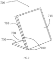
FIG. 2 is a schematic diagram illustrating another state of the bendable mobile terminal ofFIG. 1 , with the other bendable mechanism being in a bent state. -
FIG. 3 is a schematic diagram illustrating another state of the bendable mobile terminal ofFIG. 1 , with both the two bendable mechanisms being in a bent state. -
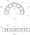
FIG. 4 is a structure schematic diagram of the bendable mechanism ofFIG. 1 , which is in a bent state, according to a first embodiment. -
FIG. 5 is a side view of the bendable mechanism ofFIG. 4 , which is in a fully deployed state. -
FIG. 6 is a plan view of the bendable mechanism ofFIG. 4 , which is in a fully deployed state. -
FIG. 7 is a structure schematic diagram of the bendable mechanism ofFIG. 1 , which is in a fully deployed state, according to a second embodiment. -
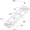
FIG. 8 is a structure schematic diagram of the bendable mechanism ofFIG. 1 , which is in a fully deployed state, according to a third embodiment. -
FIG. 9 is a structure schematic diagram of the bendable mechanism ofFIG. 1 , which is in a fully deployed state, according to a fourth embodiment. -
FIG. 10 is a structure schematic diagram of the bendable mechanism ofFIG. 9 , which is in a bent state. - The technical solutions of embodiments of the present disclosure will be described clearly and completely in combination with the accompanying drawings of the embodiments of the present disclosure.
- Referring to
FIGs. 1 to 3 , the present disclosure provides a bendablemobile terminal 700, which may be a mobile terminal device such as a tablet computer, a mobile phone, a notebook, and so on. The bendablemobile terminal 700 includes twobendable mechanisms 100, and the bendablemobile terminal 700 is capable of being bent at the locations of the twobendable mechanisms 100. One of thebendable mechanisms 100 is located at a middle portion of the bendablemobile terminal 700, and the otherbendable mechanism 100 is located at a middle portion between the one bendable mechanism and one side of the bendable mobile terminal. Therefore, the bendablemobile terminal 700 is able to be in a state of being folded in half as illustrated inFIG. 1 , with only one of thebendable mechanisms 100 being bent; or in a first standing state as illustrated inFIG. 2 , with only the otherbendable mechanism 100 being bent; or in a second standing state as illustrated inFIG. 3 , with both of the twobendable mechanisms 100 being bent; or in a fully deployed state (not illustrated) with both of the twobendable mechanisms 100 not being bent. It can be seen that, with the arrangement of the twobendable mechanisms 100, the bendablemobile terminal 700 can provide its own supporting function when any one of thebendable mechanisms 100 being bent, thereby additional supporting components, and improving the portability of the mobile terminal. - Specifically, in the present embodiment, the bendable
mobile terminal 700 further includes afirst body 710, asecond body 720, athird body 730, and adisplay screen 740. Thefirst body 710, thesecond body 720, and thethird body 730 are housings, and may accommodate components such as chips, batteries, cameras, and so on. Thefirst body 710, thesecond body 720 and thethird body 730 are sequentially connected. Thefirst body 710 and thesecond body 720, thesecond body 720 and thethird body 730 are respectively connected through thebendable mechanisms 100. Thefirst body 710, thesecond body 720 and thethird body 730 are respectively provided with a first bearingsurface 711, a second bearingsurface 721 and a third bearingsurface 731. When the bendablemobile terminal 700 is fully deployed, the first bearingsurface 711, the second bearingsurface 721 and the third bearingsurface 731 are together to form a plane or a nearly plane. The areas of the second bearingsurface 721 and the third bearingsurface 731 are both smaller than the area of the first bearingsurface 711. In the present embodiment, the area of the first bearingsurface 711 is larger than the sum of the areas of the second bearingsurface 721 and the third bearingsurface 731, and the area of the second bearingsurface 721 is substantially equal to the area of the third bearingsurface 731. That is, one of thebendable mechanisms 100 is located at a position of about a half of the bendablemobile terminal 700, and the otherbendable mechanism 100 is located at a position of about one quarter of the bendablemobile terminal 700. - In the present embodiment, the
display screen 740 includes a flexible display screen, the flexible display screen is located on a surface which is cooperatively formed by the first bearingsurface 711, the second bearingsurface 721, and the third bearingsurface 731, that is, the first bearingsurface 711, the second bearingsurface 721, and the third bearingsurface 731 are configured to cooperatively bear thedisplay screen 740. Of course, in other embodiments, thethird body 730 may not be provided with thedisplay screen 740. Alternatively, thedisplay screen 740 may include a flexible display screen and a non-flexible display screen, and the flexible display screen is located on a surface formed by the first bearingsurface 711 and the second bearingsurface 721, and the non-flexible display screen is located on the third bearingsurface 731. - The bendable
mobile terminal 700 mainly includes four working states. The first working state is a fully deployed state (not illustrated), that is, thefirst body 710, thesecond body 720 and thethird body 730 are coplanar, and the display screen is a flat surface, in this case, the flexiblemobile terminal 700 can be used as a common tablet computer or a mobile phone. The second working state is a folded state, and in this case, the bendablemobile terminal 700 is folded in half through thebendable mechanism 100 located between thefirst body 710 and thesecond body 720. This working status is easy to be carried. The third working state is a first standing state, and in this case, the bendablemobile terminal 700 can stand approximately when thebendable mechanism 100 located between thesecond body 720 and thethird body 730 being bent. Due to the self-balance of the bendablemobile terminal 700, in the third working state, only a small angle can be bent. And in this state, the third body serves as a support, so that a portion of thedisplay screen 740 covering the third bearingsurface 731 does not display any image in an operating state, thereby saving energy consumption. The fourth working state is a second standing state, and in this case, both the twobendable mechanisms 100 are bent, so that thesecond body 720 serves as a support, with the first bearingsurface 711 and the third bearingsurface 731 facing opposite directions. In this state, a portion of thedisplay screen 740 covering the second carryingsurface 721 does not display any image in an operating state, thereby saving energy consumption. Thedisplay screen 740 covering the first carryingsurface 711 and the third carryingsurface 731 may be used simultaneously. The bendablemobile terminal 700 may also stay at a bent position under any bending state, so that the user may adjust the position according to actual needs. - Further,
FIGs. 4 to 6 illustrate structure schematic diagrams of the bendable mechanism of the bendable mobile terminal ofFIG. 1 , according to a first embodiment. The bendable mechanism includes n bending portions and n-1 connecting portions, where n is an integer greater than or equal to two. Specifically, thebendable mechanism 100 includes sixbending portions 130 and five connectingportions 170. Twoadjacent bending portions 130 are rotatably connected through the connectingportion 170 and form a chain-type structure. Thebending portion 130 is a block with its bottom surface appearing a "" shape. The
bending portion 130 includes afirst end 131 and asecond end 132 opposite to each other. Two opposite edges of thefirst end 131 are respectively provided with afirst hinge portion 133. Thefirst hinge portion 133 may be a cylindrical protrusion or a hinge hole. In the present embodiment, thefirst hinge portion 133 is preferably a hinge hole. The edges of two opposite sides of thesecond end 132 are respectively provided with a firstabutting portion 134. The first abuttingportions 134 are two opposite corners on thesecond end 132 of the bendingportion 130. Two opposite sides of the bendingportion 130 respectively define agroove 135. Thegroove 135 penetrates through thefirst end 131 of the bending portion. Thefirst hinge portion 133 are arranged on two opposite walls of thegroove 135. - Further, the connecting
portion 170 is a rectangular block. Two opposite edges of one end of the connectingportion 170 are respectively provided with asecond hinge portion 171 hinged with thefirst hinge portion 133. The second hinge portion 172 may be a hinge hole or a cylindrical protrusion. In the present embodiment, the second hinge portion 172 is preferably a hinge hole passing through the connectingportion 170. Thefirst hinge portion 133 and thesecond hinge portion 171 are hinged and closely fitted with each other through a pin shaft, and the closely fitting increases frictional force, therefore, the bendingportion 130 may stay at any position after rotated with respect to the connectingportion 170. Two ends of the connectingportion 170 connected to the end where thesecond hinge portion 171 is located can be received in twoopposite grooves 135 on twoadjacent bending portions 130. The arrangement of thegroove 135 increases the rotatable angle of the bendingportion 130 relative to the connectingportion 170. - Further, the first ends 131 of the six bending
portions 130 joint together to form asupport surface 110. It should be understood that, thesupport surface 110 may also be cooperatively formed by the end surface of thefirst end 131 of thebent portion 130 and the end surface of the connectingportion 170 where thesecond hinge portion 171 is located, as long as the support function can be achieve without prejudice to prevent the bendable mechanism to be bent. When thebendable mechanism 100 is fully deployed, thesupport surface 110 is a flat surface or is substantially a flat surface, and thesupport surface 110 can provide support for various bending states of the flexible display screen of the mobile terminal. The direction opposite to thesupport surface 110 is a first direction, and thebendable mechanism 130 may be bent toward the first direction in an arc shape. When thebendable mechanism 100 is bent, the six bendingportions 130 rotate together toward the first direction and can stay at any bent position. When the opposite first abuttingportions 134 of twoadjacent bending portions 130 abut against each other, thebendable mechanism 100 is in the first bending state. The first bending state refers to thebendable mechanism 100 reaches a minimum bending radius of curvature, that is, an extreme position for thebendable mechanism 100 after being bent. -
FIG. 7 illustrates a structure schematic diagram of the bendable mechanism of the bendable mobile terminal ofFIG. 1 , according to a second embodiment. The bendable mechanism includes n bending portions and n-1 connecting portions, where n is an integer greater than or equal to two. Specifically, thebendable mechanism 200 includes five bending portions 230 and four connecting portions 270. Two adjacent bending portions 230 are rotatably connected through the connecting portion 270 and form a chain-type structure. - Further, the bending portion 230 is a straight prism with its bottom surface is an isosceles triangle and/or an isosceles trapezoid. When the bottom surface is an isosceles triangle, two edges connected by the bottom edge of the bottom surface are respectively provided with a third hinge portion. When the bottom surface is an isosceles trapezoid, two edges connected by the lower bottom edge of the bottom surface are respectively provided with a third hinge portion. In the present embodiment, the bending portion 230 is a straight prism with its
bottom surface 234 having an isosceles trapezoid shaped. Twoedges 231 connected by the longer lower bottom edge of the two bottom edges of thebottom surface 234 are respectively provided with athird hinge portion 232. Thethird hinge portion 232 is a number of hinge holes or hinge tabs arranged along theedge 231. The connecting portion is a pin shaft (not labeled). Thethird hinge portions 232 on two adjacent bending portions 230 are hinged and closely fitted with each other through the connecting portions, and the close fitting increases frictional force, therefore, the bending portions 230 may stay at any position after rotating with respect to an adjacent bending portion 230. - Further, the surface where the two
edges 231 of the five bending portions 230 are commonly located forms asupport surface 210. When thebendable mechanism 200 is fully deployed, thesupport surface 210 is a flat surface, and thesupport surface 210 can provide support for various bending states of the flexible display screen of the mobile terminal. The direction opposite to thesupport surface 210 is a first direction, and the bendable mechanism 230 may be bent toward the first direction in an arc shape. When thebendable mechanism 200 is bent, the five bending portions 230 rotate together toward the first direction and can stay at any bent position. Two opposite surfaces each having anedge 231 are second abuttingportions 233. When the opposite second abuttingportions 233 of two adjacent bending portions 230 abut against each other, thebendable mechanism 200 is in the first bending state, that is, thebendable mechanism 200 reaches a minimum bending radius of curvature. -
FIG. 8 illustrates a structure schematic diagram of the bendable mechanism of the bendable mobile terminal ofFIG. 1 , according to a third embodiment. The bendable mechanism includes n bending portions and n-1 connecting portions, where n is an integer greater than or equal to three. Preferably, thebendable mechanism 400 includes four bendingportions 430 and three connectingportions 470. Two adjacent bendingportions 430 are rotatably connected through the connectingportion 470 and form a bendable chain-type structure. The bendingportion 430 is a rod. Four bendingportions 430 are arranged side by side and adjacent to each other. Each of the bendingportions 430 defines a number of firstexternal gears 431 and a number of secondexternal gears 432 along its axial direction. In the present embodiment, the amount of the firstexternal gear 431 and the secondexternal gear 432 are respectively two. The two firstexternal gears 431 and the two secondexternal gears 432 are respectively defined on two opposite ends of the bendingportion 430. The firstexternal gears 431 on one of the bendingportions 430 mesh with the firstexternal gears 431 on the bendingportion 430 adjacent to one side of the onebending portions 430, and the secondexternal gears 432 on the onebending portions 430 mesh with the secondexternal gear 432 on the bendingportion 430 adjacent to the other side of the onebending portions 430. The meshing among the gears can prevent the bendingportions 430 from slipping during positioning. - Further, the connecting
portion 470 is a thin-walled sleeve. The connectingportion 470 is sleeved on twoadjacent bending portions 430 and closely fitted, and the close fitting increases the frictional force, therefore, the bendingportion 430 may stay at any position after rotating with respect to theadjacent bending portions 430. The surfaces composed by the bendingportions 430 arranged side by side form a support surface. It should be understood that, thebendable mechanism 400 may include two opposite support surfaces. In the present embodiment, any one of them is selected to be thesupport surface 410. Thesupport surface 410 can provide support for various bending states of the flexible display screen of the mobile terminal. The direction opposite to thesupport surface 410 is a first direction, and thebendable mechanism 430 may be bent toward the first direction in an arc shape. The fourbending portions 430 rotate together toward the first direction and can stay at any bent position. -
FIGs. 9 to 10 illustrates structure schematic diagrams of the bendable mechanism of the bendable mobile terminal ofFIG. 1 , according to a fourth embodiment. Thebendable mechanism 300 is a rectangular plate with a groove on its surface. Thebendable mechanism 300 is integrally formed of a special material that has the property of keeping its shape after being bent and staying at the bent position, such as galvanized steel. One surface of thebendable mechanism 300 is provided with V-shaped grooves arranged in parallel and spaced apart. The V-shaped grooves are arranged along an extending direction of the surface and across two ends of the surface. A portion penetrating through along the extending direction of the surface and connecting between two adjacent V-shaped grooves is a bump. The bump forms a bendingportion 330, and the V-shaped groove forms a connectingportion 370. Two adjacent bendingportions 330 are connected through the connectingportion 370 and form a bendable chain-type structure. In the present embodiment, the amount of the bendingportions 330 is four, and the amount of the connecting portions is three. The outer surface of thebendable mechanism 300 is preferably wrapped with injection-molded rubber material to protect and prolong the service life of thebendable mechanism 300. - Further, a surface of the
bendable mechanism 300 opposite to the surface where the connectingportion 370 is located is asupport surface 310, and thesupport surface 310 can provide support for various bending states of the flexible display screen of the mobile terminal. The direction opposite to thesupport surface 310 is a first direction, and thebendable mechanism 300 may be bent toward the first direction in an arc shape. When thebendable mechanism 300 is bent, the four bendingportions 330 rotate together toward the first direction and can stay at any bent position. When two opposite sides of each connectingportions 370 abut against each other, thebendable mechanism 300 is in the first bending state, that is, thebendable mechanism 300 reaches a minimum bending radius of curvature. - It should be understood that, the bendable mechanism of the bendable mobile terminal 700 can adopt one or a combination of any two of the bendable mechanisms in the first to fourth embodiments described above.
- The above are the preferred embodiments of the present disclosure. It should be noted that those skilled in the art may still make various improvements and modifications without departing from the principle of the present disclosure, and such improvements and modifications are also considered to be within the scope of the present disclosure.
Claims (16)
Applications Claiming Priority (1)
| Application Number | Priority Date | Filing Date | Title |
|---|---|---|---|
| PCT/CN2015/100314 WO2017113393A1 (en) | 2015-12-31 | 2015-12-31 | Bendable mobile terminal |
Publications (2)
| Publication Number | Publication Date |
|---|---|
| EP3399516A1 true EP3399516A1 (en) | 2018-11-07 |
| EP3399516A4 EP3399516A4 (en) | 2019-08-14 |
Family
ID=59224290
Family Applications (1)
| Application Number | Title | Priority Date | Filing Date |
|---|---|---|---|
| EP15912017.9A Withdrawn EP3399516A4 (en) | 2015-12-31 | 2015-12-31 | Bendable mobile terminal |
Country Status (4)
| Country | Link |
|---|---|
| US (1) | US10429894B2 (en) |
| EP (1) | EP3399516A4 (en) |
| CN (1) | CN107408362B (en) |
| WO (1) | WO2017113393A1 (en) |
Families Citing this family (34)
| Publication number | Priority date | Publication date | Assignee | Title |
|---|---|---|---|---|
| USD353539S (en) * | 1990-07-20 | 1994-12-20 | Norden Pac Development Ab | Combined tube and cap |
| KR102701604B1 (en) * | 2017-02-23 | 2024-09-03 | 삼성전자주식회사 | Out-foldable electronic apparatus and control method thereof |
| WO2018229941A1 (en) * | 2017-06-15 | 2018-12-20 | シャープ株式会社 | Display device |
| KR20200030557A (en) * | 2017-07-17 | 2020-03-20 | 쓰리엠 이노베이티브 프로퍼티즈 컴파니 | Curvature limiting film |
| CN110770814B (en) * | 2017-08-03 | 2021-11-16 | 深圳市柔宇科技股份有限公司 | Folding mechanism and terminal |
| WO2019024044A1 (en) * | 2017-08-03 | 2019-02-07 | 深圳市柔宇科技有限公司 | Folding mechanism and terminal |
| USD893475S1 (en) * | 2017-10-11 | 2020-08-18 | Samsung Display Co., Ltd. | Display device |
| USD885381S1 (en) * | 2017-10-11 | 2020-05-26 | Samsung Display Co., Ltd. | Display device |
| USD891427S1 (en) * | 2017-11-13 | 2020-07-28 | Samsung Display Co., Ltd. | Display device |
| CN110720083B (en) * | 2017-12-20 | 2023-07-04 | 谷歌有限责任公司 | Foldable display device with multiple pages |
| KR102450111B1 (en) * | 2017-12-28 | 2022-10-05 | 삼성디스플레이 주식회사 | Display device |
| KR102583233B1 (en) * | 2018-02-12 | 2023-09-26 | 삼성디스플레이 주식회사 | Foldable display device |
| CN112313729A (en) * | 2018-03-12 | 2021-02-02 | 深圳市柔宇科技股份有限公司 | Bending components and flexible display devices |
| WO2019223013A1 (en) * | 2018-05-25 | 2019-11-28 | 深圳市柔宇科技有限公司 | Bendable mechanism, bendable display module, and bendable terminal |
| CN111344771A (en) * | 2018-05-28 | 2020-06-26 | 华为技术有限公司 | Foldable display device |
| USD925525S1 (en) * | 2019-02-22 | 2021-07-20 | Samsung Display Co., Ltd. | Display device |
| CN111091755A (en) * | 2019-04-19 | 2020-05-01 | 广东小天才科技有限公司 | Eye-protecting panel with turnover screen |
| KR102747652B1 (en) * | 2019-06-05 | 2024-12-31 | 삼성전자주식회사 | Foldable electronic device |
| EP3986739A1 (en) | 2019-06-20 | 2022-04-27 | Corning Incorporated | Supports for dynamically bendable auto interior cover materials |
| USD1020731S1 (en) * | 2019-06-27 | 2024-04-02 | Intel Corporation | Computer with a wrap around display |
| CN110609588A (en) * | 2019-08-14 | 2019-12-24 | 联想(北京)有限公司 | Connecting devices and electronic equipment |
| WO2021078366A1 (en) * | 2019-10-22 | 2021-04-29 | Huawei Technologies Co., Ltd. | Hinge assembly for controlled folding of an electronic device |
| CN112751952B (en) * | 2019-10-30 | 2022-03-11 | 北京小米移动软件有限公司 | Mobile terminal cover and mobile terminal |
| TWI727637B (en) * | 2020-01-31 | 2021-05-11 | 友達光電股份有限公司 | Bendable display device |
| WO2021158014A1 (en) * | 2020-02-07 | 2021-08-12 | 엘지전자 주식회사 | Display device |
| USD979527S1 (en) * | 2020-02-24 | 2023-02-28 | Beijing Xiaomi Mobile Software Co., Ltd. | Mobile phone |
| CN113744634A (en) * | 2020-05-29 | 2021-12-03 | 华为技术有限公司 | Display device and electronic apparatus |
| CN113936549A (en) * | 2020-06-29 | 2022-01-14 | 云谷(固安)科技有限公司 | Bending spacer, display panel and display device |
| US11190629B1 (en) * | 2020-08-17 | 2021-11-30 | Wei Hu Koh | Sectioned wearable smartphone devices |
| CN112581864B (en) * | 2020-09-24 | 2025-03-11 | 东莞市驭舟精密科技有限公司 | A rotating shaft mechanism for a flexible screen |
| KR20230094203A (en) * | 2021-12-20 | 2023-06-28 | 삼성디스플레이 주식회사 | Electronic device |
| CN115394188A (en) * | 2022-07-20 | 2022-11-25 | 合肥维信诺科技有限公司 | Display panel and electronic device |
| US12566911B2 (en) | 2022-09-30 | 2026-03-03 | Honeywell International Inc. | Machine learning tool for layout design of printed circuit board |
| WO2026059032A1 (en) * | 2024-09-11 | 2026-03-19 | 삼성전자주식회사 | Multi-foldable electronic device |
Family Cites Families (41)
| Publication number | Priority date | Publication date | Assignee | Title |
|---|---|---|---|---|
| EP1264230A2 (en) * | 2000-01-24 | 2002-12-11 | Spotware Technologies, Inc. | Compactable/convertible modular pda |
| US7446757B2 (en) * | 2002-09-17 | 2008-11-04 | Brother Kogyo Kabushiki Kaisha | Foldable display, input device provided with the display and foldable keyboard, and personal computer provided with the input device |
| US8860632B2 (en) * | 2008-09-08 | 2014-10-14 | Qualcomm Incorporated | Multi-panel device with configurable interface |
| KR101067587B1 (en) * | 2010-01-29 | 2011-09-27 | 주식회사 팬택 | Flexible terminal with shape conversion characteristics, shape conversion method and shape conversion device |
| TWM395340U (en) * | 2010-08-04 | 2010-12-21 | Micro Star Int Co Ltd | Foldable electronic apparatus |
| TWM395341U (en) * | 2010-08-04 | 2010-12-21 | Micro Star Int Co Ltd | Foldable electronic apparatus |
| KR101227644B1 (en) * | 2010-08-10 | 2013-01-30 | 유상규 | Rollable flexible display device |
| CN201788636U (en) * | 2010-08-16 | 2011-04-06 | 苏加兴 | Foldable LED display screen |
| US9176535B2 (en) * | 2011-06-03 | 2015-11-03 | Microsoft Technology Licensing, Llc | Flexible display flexure assembly |
| KR101320384B1 (en) * | 2011-06-30 | 2013-10-23 | 삼성디스플레이 주식회사 | Flexible display panel and the display apparatus comprising the flexible display panel |
| US8605421B2 (en) * | 2011-08-17 | 2013-12-10 | Creator Technology B.V. | Display device with flexible display |
| CN202210385U (en) * | 2011-09-20 | 2012-05-02 | 深圳市安科讯实业有限公司 | Display screen protective leather folder |
| US8897731B2 (en) * | 2012-03-02 | 2014-11-25 | Apple Inc. | Methods and apparatus for adaptive receiver diversity in a wireless network |
| US9120290B2 (en) * | 2012-10-10 | 2015-09-01 | Universal Display Corporation | Flexible screen backed with rigid ribs |
| US9158332B2 (en) * | 2012-10-22 | 2015-10-13 | Nokia Technologies Oy | Limiting movement |
| US9348362B2 (en) * | 2013-02-08 | 2016-05-24 | Samsung Electronics Co., Ltd. | Flexible portable terminal |
| KR102081932B1 (en) * | 2013-03-21 | 2020-04-14 | 엘지전자 주식회사 | Display device and method for controlling the same |
| CN104135831A (en) | 2013-04-30 | 2014-11-05 | 鸿富锦精密工业(深圳)有限公司 | Flexible electronic device |
| KR102032383B1 (en) * | 2013-06-03 | 2019-11-11 | 삼성디스플레이 주식회사 | Display panel and manufacturing method thereof |
| CN203397633U (en) * | 2013-06-20 | 2014-01-15 | 湖北爱商光电股份有限公司 | Foldable LED (Light-Emitting Diode) display screen |
| US9395070B2 (en) * | 2013-07-19 | 2016-07-19 | Semiconductor Energy Laboratory Co., Ltd. | Support of flexible component and light-emitting device |
| KR102105959B1 (en) * | 2013-07-22 | 2020-04-29 | 엘지전자 주식회사 | Foldable display device providing image layer and method for controlling the same |
| KR101663728B1 (en) * | 2013-08-26 | 2016-10-07 | 삼성전자주식회사 | foldable electronic device having flexible display |
| KR101547640B1 (en) * | 2013-09-16 | 2015-08-27 | (주) 프렉코 | Foldable flexible display device with guide device |
| TWI647607B (en) * | 2013-10-11 | 2019-01-11 | 半導體能源研究所股份有限公司 | Portable data processing device and method for driving the portable data processing device |
| KR102123997B1 (en) * | 2013-11-25 | 2020-06-18 | 삼성디스플레이 주식회사 | Flexible display |
| KR20250078585A (en) * | 2013-11-28 | 2025-06-02 | 가부시키가이샤 한도오따이 에네루기 켄큐쇼 | Electronic device and driving method thereof |
| KR20230175342A (en) * | 2014-05-06 | 2023-12-29 | 가부시키가이샤 한도오따이 에네루기 켄큐쇼 | Electronic device |
| KR102226694B1 (en) * | 2014-09-01 | 2021-03-11 | 엘지디스플레이 주식회사 | Foldable display apparatus |
| KR20160041693A (en) * | 2014-10-08 | 2016-04-18 | 엘지전자 주식회사 | Mobile terminal |
| CN204331666U (en) * | 2014-12-19 | 2015-05-13 | 上海协度电子科技有限公司 | Folding display screen |
| CN204463715U (en) * | 2014-12-26 | 2015-07-08 | 上海摩软通讯技术有限公司 | Bend unit, flexible display screen and mobile terminal |
| KR102318656B1 (en) * | 2015-01-05 | 2021-10-28 | 삼성디스플레이 주식회사 | Apparatus for supporting display panel |
| JP6404158B2 (en) * | 2015-03-30 | 2018-10-10 | 株式会社ジャパンディスプレイ | Display device |
| CN104851365B (en) | 2015-05-28 | 2017-07-04 | 京东方科技集团股份有限公司 | Folding display device |
| CN106325373B (en) * | 2015-06-30 | 2024-06-21 | 联想(北京)有限公司 | Electronic device and information processing method |
| CN105159405B (en) * | 2015-09-16 | 2020-01-31 | 联想(北京)有限公司 | Information processing method and electronic equipment |
| CN105407194A (en) * | 2015-12-29 | 2016-03-16 | 广东欧珀移动通信有限公司 | Mobile terminal with flexible screen |
| KR20170084504A (en) * | 2016-01-12 | 2017-07-20 | 삼성전자주식회사 | Electronic device and wearing form recognizing method therefor |
| KR20180039342A (en) * | 2016-10-10 | 2018-04-18 | 삼성전자주식회사 | the Electronic Device including the Flexible Display |
| KR102716181B1 (en) * | 2016-11-18 | 2024-10-11 | 삼성디스플레이 주식회사 | Foldable display device |
-
2015
- 2015-12-31 EP EP15912017.9A patent/EP3399516A4/en not_active Withdrawn
- 2015-12-31 US US15/769,691 patent/US10429894B2/en not_active Expired - Fee Related
- 2015-12-31 WO PCT/CN2015/100314 patent/WO2017113393A1/en not_active Ceased
- 2015-12-31 CN CN201580075354.5A patent/CN107408362B/en not_active Expired - Fee Related
Also Published As
| Publication number | Publication date |
|---|---|
| US10429894B2 (en) | 2019-10-01 |
| CN107408362A (en) | 2017-11-28 |
| EP3399516A4 (en) | 2019-08-14 |
| US20180314299A1 (en) | 2018-11-01 |
| CN107408362B (en) | 2020-04-14 |
| WO2017113393A1 (en) | 2017-07-06 |
Similar Documents
| Publication | Publication Date | Title |
|---|---|---|
| US10429894B2 (en) | Bendable mobile terminal | |
| KR102450835B1 (en) | Foldable mechanism and its display device | |
| US9888100B2 (en) | Foldable display device | |
| EP4142267B1 (en) | Support structure, screen assembly and electronic device | |
| KR102344937B1 (en) | Structure of Hinge including a detent structure and Foldable Electronic Device including the same | |
| US11960331B2 (en) | Foldable apparatus and electronic device | |
| US10705563B2 (en) | Foldable terminal | |
| US8534619B2 (en) | Support stand for electronic device | |
| KR102413137B1 (en) | Rotating Shafts and Electronic Devices | |
| WO2017114469A1 (en) | Foldable terminal | |
| US11070711B2 (en) | Terminal, screen assembly, and electronic device | |
| CN115013421B (en) | Folding mechanism and terminal equipment | |
| CN105283004B (en) | Foldable electronic device and limiting structure | |
| EP4512985A3 (en) | Electronic device including hinge structure with arm structure | |
| KR102178724B1 (en) | Hinge unit and Foldable display apparatus having the same | |
| CN105867533B (en) | Electronic equipment | |
| CN109058284B (en) | Rotating assembly, hinge and electronic equipment | |
| US8339777B2 (en) | Portable electronic device with improved pivoting range | |
| MX2012003110A (en) | Variable display area type display device. | |
| CN105407194A (en) | Mobile terminal with flexible screen | |
| US7690081B2 (en) | Hinge for laptop computer | |
| US20250155928A1 (en) | Flexible display device | |
| US12222764B2 (en) | Foldable display device | |
| KR20190108668A (en) | Subsidary hinge system of portable device within flexible display | |
| EP2696254A3 (en) | Pivoting, multi-configuration mobile device with auto change |
Legal Events
| Date | Code | Title | Description |
|---|---|---|---|
| STAA | Information on the status of an ep patent application or granted ep patent |
Free format text: STATUS: THE INTERNATIONAL PUBLICATION HAS BEEN MADE |
|
| PUAI | Public reference made under article 153(3) epc to a published international application that has entered the european phase |
Free format text: ORIGINAL CODE: 0009012 |
|
| STAA | Information on the status of an ep patent application or granted ep patent |
Free format text: STATUS: REQUEST FOR EXAMINATION WAS MADE |
|
| 17P | Request for examination filed |
Effective date: 20180416 |
|
| AK | Designated contracting states |
Kind code of ref document: A1 Designated state(s): AL AT BE BG CH CY CZ DE DK EE ES FI FR GB GR HR HU IE IS IT LI LT LU LV MC MK MT NL NO PL PT RO RS SE SI SK SM TR |
|
| AX | Request for extension of the european patent |
Extension state: BA ME |
|
| DAV | Request for validation of the european patent (deleted) | ||
| DAX | Request for extension of the european patent (deleted) | ||
| A4 | Supplementary search report drawn up and despatched |
Effective date: 20190711 |
|
| RIC1 | Information provided on ipc code assigned before grant |
Ipc: G09F 9/30 20060101AFI20190705BHEP Ipc: G06F 1/3218 20190101ALN20190705BHEP Ipc: G06F 1/16 20060101ALI20190705BHEP Ipc: G06F 1/3234 20190101ALN20190705BHEP |
|
| STAA | Information on the status of an ep patent application or granted ep patent |
Free format text: STATUS: EXAMINATION IS IN PROGRESS |
|
| 17Q | First examination report despatched |
Effective date: 20200327 |
|
| STAA | Information on the status of an ep patent application or granted ep patent |
Free format text: STATUS: THE APPLICATION HAS BEEN WITHDRAWN |
|
| 18W | Application withdrawn |
Effective date: 20200909 |