EP3399413A1 - Component logical threads quantity adjustment method and device - Google Patents
Component logical threads quantity adjustment method and device Download PDFInfo
- Publication number
- EP3399413A1 EP3399413A1 EP16880970.5A EP16880970A EP3399413A1 EP 3399413 A1 EP3399413 A1 EP 3399413A1 EP 16880970 A EP16880970 A EP 16880970A EP 3399413 A1 EP3399413 A1 EP 3399413A1
- Authority
- EP
- European Patent Office
- Prior art keywords
- logical threads
- component
- logical
- threads
- added
- Prior art date
- Legal status (The legal status is an assumption and is not a legal conclusion. Google has not performed a legal analysis and makes no representation as to the accuracy of the status listed.)
- Granted
Links
Images



Classifications
-
- G—PHYSICS
- G06—COMPUTING OR CALCULATING; COUNTING
- G06F—ELECTRIC DIGITAL DATA PROCESSING
- G06F9/00—Arrangements for program control, e.g. control units
- G06F9/06—Arrangements for program control, e.g. control units using stored programs, i.e. using an internal store of processing equipment to receive or retain programs
- G06F9/46—Multiprogramming arrangements
- G06F9/50—Allocation of resources, e.g. of the central processing unit [CPU]
- G06F9/5005—Allocation of resources, e.g. of the central processing unit [CPU] to service a request
- G06F9/5027—Allocation of resources, e.g. of the central processing unit [CPU] to service a request the resource being a machine, e.g. CPUs, Servers, Terminals
- G06F9/505—Allocation of resources, e.g. of the central processing unit [CPU] to service a request the resource being a machine, e.g. CPUs, Servers, Terminals considering the load
-
- G—PHYSICS
- G06—COMPUTING OR CALCULATING; COUNTING
- G06F—ELECTRIC DIGITAL DATA PROCESSING
- G06F9/00—Arrangements for program control, e.g. control units
- G06F9/06—Arrangements for program control, e.g. control units using stored programs, i.e. using an internal store of processing equipment to receive or retain programs
- G06F9/46—Multiprogramming arrangements
- G06F9/50—Allocation of resources, e.g. of the central processing unit [CPU]
- G06F9/5005—Allocation of resources, e.g. of the central processing unit [CPU] to service a request
- G06F9/5027—Allocation of resources, e.g. of the central processing unit [CPU] to service a request the resource being a machine, e.g. CPUs, Servers, Terminals
-
- G—PHYSICS
- G06—COMPUTING OR CALCULATING; COUNTING
- G06F—ELECTRIC DIGITAL DATA PROCESSING
- G06F9/00—Arrangements for program control, e.g. control units
- G06F9/06—Arrangements for program control, e.g. control units using stored programs, i.e. using an internal store of processing equipment to receive or retain programs
- G06F9/46—Multiprogramming arrangements
- G06F9/50—Allocation of resources, e.g. of the central processing unit [CPU]
- G06F9/5083—Techniques for rebalancing the load in a distributed system
-
- G—PHYSICS
- G06—COMPUTING OR CALCULATING; COUNTING
- G06F—ELECTRIC DIGITAL DATA PROCESSING
- G06F2209/00—Indexing scheme relating to G06F9/00
- G06F2209/50—Indexing scheme relating to G06F9/50
- G06F2209/5018—Thread allocation
-
- G—PHYSICS
- G06—COMPUTING OR CALCULATING; COUNTING
- G06F—ELECTRIC DIGITAL DATA PROCESSING
- G06F2209/00—Indexing scheme relating to G06F9/00
- G06F2209/50—Indexing scheme relating to G06F9/50
- G06F2209/503—Resource availability
Definitions
- the present disclosure relates to the field of the Internet, and, more particularly, to a method and an apparatus for adjusting the number of component logical threads.
- a computer cluster may be disposed in a distributed real-time computing system.
- Real-time computing of data may be implemented by using the computer cluster.
- a master device and a plurality of slave devices may be disposed in the cluster.
- a real-time computing program is stored in the master device.
- the real-time computing program in the master device will invoke resources in the slave devices to implement data computing.
- the real-time computing program is composed of multiple components and each component executes a specific task.
- the slave devices may provide multiple logical thread resources for the master device to invoke. Therefore, the master device generally pre-allocates fixed logical thread resources to each component in the real-time computing program. When there is data that needs to be processed, each component in the real-time computing program will invoke the pre-allocated logical thread resources to execute a task, thus completing computing of the data.
- the data amount of externally input data is not fixed, while the logical thread resources allocated to each component are fixed.
- each component has many tasks to process.
- the component will have low execution efficiency, affecting real-time computing of the data.
- resources will be wasted. Therefore, a method and an apparatus for adjusting the number of component logical threads are urgently needed in the conventional techniques, to improve the utilization rate of resources while ensuring real-time computing of data.
- the example embodiments of the present disclosure provide a method and an apparatus for adjusting the number of component logical threads, to improve the utilization rate of resources while ensuring real-time computing of data.
- the present disclosure discloses a method for adjusting the number of component logical threads, including:
- the step of adjusting the number of logical threads of the component according to the determination result includes: adjusting the number of logical threads of the component to be: the number of current logical threads of the component * the data amount of data sent by a sending apparatus per second / the data amount of data received by the component per second, the sending apparatus being an apparatus that sends data to the component.
- the abnormal load state includes a high load state and a low load state
- the utilization rate is equal to space occupied by data stored in a message queue / pre-allocated storage space of the message queue
- the step of determining a load state of each logical thread according to a utilization rate of a data processing queue corresponding to each logical thread includes:
- the step of determining whether the number of logical threads of the component needs to be adjusted according to the load states of all the logical threads of the component includes:
- the logical threads run in an operational process, and the method further includes:
- the step of determining whether logical threads are allowable to be added in an operational process associated with the current logical threads includes:
- the step of determining the number of operational processes that need to be added includes:
- the method further includes:
- the method further includes:
- the present disclosure further discloses an apparatus for adjusting the number of component logical threads, including:
- the adjustment module includes: an adjustment unit configured to adjust the number of logical threads of the component to: the number of current logical threads of the component * the data amount of data sent by a sending apparatus per second / the data amount of data received by the component per second, the sending apparatus being an apparatus that sends data to the component.
- the abnormal load state includes a high load state and a low load state
- the utilization rate is equal to space occupied by data stored in a message queue / pre-allocated storage space of the message queue
- the determination module includes:
- the apparatus further includes:
- the second determination module includes:
- the third determination unit includes:
- the apparatus further includes:
- the apparatus further includes:
- a load state of each logical thread is determined according to a utilization rate of a data processing queue corresponding to each logical thread, the load state including a normal load state and an abnormal load state. Then, according to the load states of the logical threads of the component, whether the number of logical threads of the component needs to be adjusted is determined. Finally, the number of logical threads of the component is adjusted according to the determination result if the number of logical threads of the component needs to be adjusted.
- the number of logical threads that is callable by a component may be adjusted according to load states of the logical threads, thereby preventing logical threads that may be called by a component from being excessive or insufficient, thus improving the utilization rate of logical thread resources while ensuring real-time processing of data.
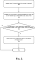
- the present disclosure discloses a method for adjusting the number of component logical threads. As shown in FIG. 1 , the method at least includes the following steps:
- each logical thread there is a data processing queue inside each logical thread.
- the data processing queue is used to store data that needs to be processed by the corresponding logical thread.
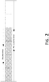
- the data processing queue may be specifically as shown in FIG. 2 , and the shaded portion represents occupied space that is already occupied by data stored in the processing queue.
- a utilization rate of a message queue space occupied by data stored in the message queue / pre-allocated storage space of the message queue.
- a load state i.e., a normal load state or an abnormal load state
- the abnormal load state may specifically include a high load state with an excessively high utilization rate and a low load state with an excessively low utilization rate.
- the logical thread cannot ensure real-time processing of data.
- the low load state logical thread resources allocated to the component will be wasted.
- Step S13 whether the number of logical threads of the component needs to be adjusted is determined according to the load states of the logical threads of the component; if yes, step S14 is performed; otherwise, the procedure ends.
- Step S14 The number of logical threads of the component is adjusted according to the determination result.
- the number of logical threads of the component may be specifically adjusted to: the number of current logical threads of the component * the data amount of data sent by a sending apparatus per second / the data amount of data received by the component per second, the sending apparatus being an apparatus that sends data to the component.
- a real-time computing program is generally composed of a Spout (message source) component and a Blot (message processing) component.
- a plurality of components may process data iteratively.
- a real-time computing program is composed of one Spout component and two Bolt components, and the two Bolt components are a first Bolt component and a second Bolt component respectively.
- the Spout component may receive data sent from a message source, and call pre-allocated logical threads to process the data.
- the Spout component serves as an upstream component to send the data to the first Bolt component that serves as a downstream component.
- the first Bolt component will serve as an upstream component to send the data to the second Bolt component that serves as a downstream component.
- the sending apparatus may be a message source device. If the current component is a Bolt component, the sending apparatus may be an upstream component of the current component.
- a load state of each logical thread is determined according to a utilization rate of a data processing queue corresponding to each logical thread, the load state including a normal load state and an abnormal load state. Then, it is determined according to the load states of the logical threads of the component whether the number of logical threads of the component needs to be adjusted. Finally, the number of logical threads of the component is adjusted according to the determination result if the number of logical threads of the component needs to be adjusted.
- the number of logical threads that may be called by a component may be adjusted according to load states of the logical threads, preventing logical threads that may be called by a component from being excessive or insufficient, thus improving the utilization rate of logical thread resources while ensuring real-time processing of data.
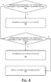
- step S12 in all the foregoing example embodiments may include the following steps: Step S41: whether a utilization rate of a data processing queue corresponding to a logical thread is greater than a first preset threshold is determined; if yes, step S42 is performed; otherwise, step S43 is performed.
- a user may set the value of the first preset threshold on his/her own as required.
- the first preset threshold is 80%.
- Step S42 the logical thread is determined in a high load state.
- a utilization rate of a data processing queue corresponding to a logical thread when a utilization rate of a data processing queue corresponding to a logical thread is greater than the first preset threshold, it indicates that the logical thread has a large amount of data to be processed but fails to process the data in real time, and it is determined that the logical thread is in a high load state.
- Step S43 whether the utilization rate of the data processing queue corresponding to the current logical thread is less than a second preset threshold is determined; if yes, step S44 is performed; otherwise, step S45 is performed.
- the user may also set the value of the second preset threshold on his/her own as required.
- the second preset threshold is 20%.
- Step S44 the logical thread is determined in a low load state.
- a utilization rate of a data processing queue corresponding to a logical thread is less than the second preset threshold, it indicates that the logical thread is idle and wastes resources, and it is determined that the logical thread is in a low load state.
- Step S45 the logical thread is determined in a normal load state.
- a utilization rate of a data processing queue corresponding to a logical thread is greater than or equal to the second preset threshold and less than or equal to the first preset threshold, it indicates that the logical thread may process data normally, that is, the logical thread may ensure real-time processing of data without wasting resources. Thus, it is determined that the logical thread is in a normal load state.
- a load state of a logical thread may be determined, and then load states of all logical threads that may be called by a component may be determined.
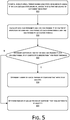
- step S13 in the all the foregoing example embodiments may include the following steps:
- load states of all the logical threads in the current component may be collected at intervals of a preset time. After the load states of all the logical threads have been collected a preset number of times, the number of logical threads in the high load state and the number of logical threads in the low load state are counted.
- Step S53 whether at least one of the high load probability and the low load probability of the component is greater than a third preset threshold is determined; if yes, step S54 is performed; otherwise, step S55 is performed.
- the user may set the value of the third preset threshold on his/her own as required.
- the third preset threshold may be set to 80%.
- step S54 may be performed when the high load probability of the component is greater than the third preset threshold; or step S54 may be performed when the low load probability of the component is greater than the third preset threshold; or step S54 may be performed when both the high load probability and the low load probability of the component are greater than the third preset threshold.
- Step S54 the number of logical threads of the component that needs to be adjusted is determined.
- Step S55 the number of logical threads of the component that does not need to be adjusted is determined.
- the logical threads in all the foregoing example embodiments all run in an operational process.
- the method in all the foregoing example embodiments may further include the following steps: Step S61: logical threads need to be added or deleted for the component are determined according to the number of logical threads of the component that needs to be adjusted and the number of current logical threads.
- the number of logical threads of a component needs to be adjusted to 3 upon calculation by using the foregoing method, and the number of current logical threads of the component is 5. Then, it may be determined that two logical threads of the component need to be deleted currently.
- Step S62 whether logical threads are allowable to be added in an operational process associated with the current logical threads is determined, if the logical threads need to be added; if yes, step S63 is performed; otherwise, step S64 is performed.
- the operational process associated with the current logical threads includes all operational processes in a computer cluster where the current logical threads are located.
- Step S63 The logical threads are added in the operational process associated with the current logical threads.
- Step S64 The number of operational processes that need to be added is determined.
- Step S65 Logical threads are deleted in the operational process if the corresponding logical threads need to be deleted.
- the number of logical threads that need to be deleted may be determined according to a difference between the number of current logical threads of the component and the number of logical threads after adjustment. Then, a corresponding number of logical threads are deleted from the current component at random.
- step S62 in all the foregoing example embodiments may include the following steps: Step S71: A plurality of operational processes associated with the current logical threads is determined.
- the plurality of associated operational processes includes all operational processes in a computer cluster where the component is located.
- the total pre-allocated resources of the operational process may be CPU resources or storage space pre-allocated to the operational process
- the resources occupied by the operational process for running logical threads may be CPU resources or storage space occupied by the operational process for running the logical threads.
- the user may set the value of the third preset threshold on his/her own as required.
- the third preset threshold may be set to 80%.
- Step S73 The total number of logical threads that is allowable to be added in all the associated operational processes is counted.
- Step S74 whether the total number of logical threads that is allowable to be added is greater than or equal to the number of logical threads that need to be added for the component is determined; if yes, step S75 is performed; otherwise, step S76 is performed.
- Step S75 the logical threads are determined to be allowable to be added in the associated operational processes.
- Step S76 the logical threads are determined not to be allowable to be added in the associated operational processes.
- step S64 in all the foregoing example embodiments may include the following steps: Step S81: The number Q of logical threads that is allowable to run in the associated operational processes under a preset load threshold is acquired.
- the preset load threshold may specifically be 80% of a load limit of the operational processes.
- the method in all the foregoing example embodiments may further include:
- a component may include an upstream component and a downstream component.
- the number of logical threads that may be called by each component varies by using the method in the example embodiment of the present disclosure. Normal data transmission of logical threads between upstream and downstream components may be determined by using the method disclosed in the present disclosure.
- the method in all the foregoing example embodiments may further include:
- an operation of deleting logical threads when performed, it may cause an operational process to be empty of logical threads. In this case, the operational process does not execute any task. Resources occupied by the operational process may be released in time by using the method disclosed in the present disclosure.
- the computer software product may be stored in a storage medium, and includes several instructions for instructing a computer device (which may be a personal computer, a server, a network device, or the like) to perform all or some of the steps of the methods described in the example embodiments of the present disclosure.
- the foregoing storage medium includes: any medium that may store program codes, such as a Read-Only Memory (ROM), a Random Access Memory (RAM), a magnetic disk, or an optical disc.
- the present disclosure further provides an apparatus for adjusting the number of component logical threads.
- the apparatus includes:
- the function of the adjustment module 94 may be specifically implemented by an adjustment unit.
- the adjustment unit is configured to adjust the number of logical threads of the component to: the number of current logical threads of the component * the data amount of data sent by a sending apparatus per second / the data amount of data received by the component per second, the sending apparatus being an apparatus that sends data to the component.
- a load state of each logical thread is determined according to a utilization rate of a data processing queue corresponding to each logical thread, the load state including a normal load state and an abnormal load state. Then, it is determined according to the load states of the logical threads of the component whether the number of logical threads of the component needs to be adjusted. Finally, the number of logical threads of the component is adjusted according to the determination result if the number of logical threads of the component needs to be adjusted.
- the number of logical threads that may be called by a component may be adjusted according to load states of the logical threads, preventing logical threads that may be called by a component from being excessive or insufficient, thus improving the utilization rate of logical thread resources while ensuring real-time processing of data.
- the abnormal load state in all the foregoing example embodiments includes a high load state and a low load state, and the utilization rate is equal to space occupied by data stored in a message queue / pre-allocated storage space of the message queue; and the determination module includes:
- a load state of a logical thread may be determined.
- the judgment module in all the foregoing example embodiments includes:
- the apparatus in all the foregoing example embodiments may further include:
- the second judgment module in all the foregoing example embodiments includes:
- the third determination unit in all the foregoing example embodiments includes:
- the apparatus in all the foregoing example embodiments further includes:
- the apparatus in all the foregoing example embodiments further includes:
Landscapes
- Engineering & Computer Science (AREA)
- Software Systems (AREA)
- Theoretical Computer Science (AREA)
- Physics & Mathematics (AREA)
- General Engineering & Computer Science (AREA)
- General Physics & Mathematics (AREA)
- Data Exchanges In Wide-Area Networks (AREA)
- Debugging And Monitoring (AREA)
Abstract
Description
- The present disclosure relates to the field of the Internet, and, more particularly, to a method and an apparatus for adjusting the number of component logical threads.
- Generally, a computer cluster may be disposed in a distributed real-time computing system. Real-time computing of data may be implemented by using the computer cluster. Typically, a master device and a plurality of slave devices may be disposed in the cluster. A real-time computing program is stored in the master device. When there is data that needs to be processed (that is, when external data is input to the distributed real-time computing system), the real-time computing program in the master device will invoke resources in the slave devices to implement data computing.
- In an actual application, the real-time computing program is composed of multiple components and each component executes a specific task. The slave devices may provide multiple logical thread resources for the master device to invoke. Therefore, the master device generally pre-allocates fixed logical thread resources to each component in the real-time computing program. When there is data that needs to be processed, each component in the real-time computing program will invoke the pre-allocated logical thread resources to execute a task, thus completing computing of the data.
- In the real-time computing system, the data amount of externally input data is not fixed, while the logical thread resources allocated to each component are fixed. When a large amount of external data is input, each component has many tasks to process. In this case, if a small number of logical thread resources are pre-allocated to one component, the component will have low execution efficiency, affecting real-time computing of the data. Likewise, if a small amount of external data is input while many logical thread resources are pre-allocated to one component, resources will be wasted. Therefore, a method and an apparatus for adjusting the number of component logical threads are urgently needed in the conventional techniques, to improve the utilization rate of resources while ensuring real-time computing of data.
- The example embodiments of the present disclosure provide a method and an apparatus for adjusting the number of component logical threads, to improve the utilization rate of resources while ensuring real-time computing of data.
- To solve the foregoing technical problem, the example embodiments of the present disclosure disclose the following technical solutions:
In an aspect, the present disclosure discloses a method for adjusting the number of component logical threads, including: - acquiring a plurality of logical threads that is callable by a component;
- determining a load state of each logical thread according to a utilization rate of a data processing queue corresponding to each logical thread, the load state including a normal load state and an abnormal load state;
- determining, according to the load states of the logical threads of the component, whether the number of logical threads of the component needs to be adjusted; and
- adjusting the number of logical threads of the component according to the determination result if the number of logical threads of the component needs to be adjusted.
- Optionally, the step of adjusting the number of logical threads of the component according to the determination result includes:
adjusting the number of logical threads of the component to be: the number of current logical threads of the component * the data amount of data sent by a sending apparatus per second / the data amount of data received by the component per second, the sending apparatus being an apparatus that sends data to the component. - Optionally, the abnormal load state includes a high load state and a low load state, and the utilization rate is equal to space occupied by data stored in a message queue / pre-allocated storage space of the message queue; and the step of determining a load state of each logical thread according to a utilization rate of a data processing queue corresponding to each logical thread includes:
- determining whether a utilization rate of a data processing queue corresponding to a logical thread is greater than a first preset threshold;
- determining that the logical thread is in a high load state if the utilization rate is greater than the first preset threshold;
- determining whether the utilization rate of the data processing queue corresponding to the current logical thread is less than a second preset threshold if the utilization rate is not greater than the first preset threshold; and
- determining that the logical thread is in a low load state if the utilization rate is less than the second preset threshold.
- Optionally, the step of determining whether the number of logical threads of the component needs to be adjusted according to the load states of all the logical threads of the component includes:
- respectively counting the number of logical threads in the high load state and the number of logical threads in the low load state among all the logical threads that are callable by the component;
- calculating a high load probability and a low load probability of the component respectively by using a high load probability calculation formula and a low load probability calculation formula, the high load probability calculation formula = the number of logical threads in the high load state / the number of all the logical threads that are callable by the current component, and the low load probability calculation formula = the number of logical threads in the low load state / the number of all the logical threads that are callable by the current component;
- determining whether at least one of the high load probability and the low load probability of the component is greater than a third preset threshold; and
- determining that the number of logical threads of the component needs to be adjusted if at least one of the high load probability and the low load probability of the component is greater than the third preset threshold.
- Optionally, the logical threads run in an operational process, and the method further includes:
- determining whether logical threads need to be added or deleted for the component according to the number of logical threads that the component needs to be adjusted and the number of current logical threads;
- determining whether logical threads are allowable to be added in an operational process associated with the current logical threads if the logical threads need to be added;
- adding the logical threads in the operational process associated with the current logical threads if the logical threads are allowable to be added in the operational process associated with the current logical threads;
- determining the number of operational processes that need to be added if the logical threads cannot be added in the operational process associated with the current logical threads; and
- deleting logical threads in the operational process if the corresponding logical threads need to be deleted.
- Optionally, the step of determining whether logical threads are allowable to be added in an operational process associated with the current logical threads includes:
- determining a plurality of operational processes associated with the current logical threads;
- determining, according to a preset increase formula, the number of logical threads that is allowable to be added in each operational process, the increase formula being: the number of logical threads that is allowable to be added in the operational process = (pre-allocated total resources of the operational process / resources occupied by the operational process for running logical threads * a fourth preset value - 1) * the number of logical threads running in the current operational process;
- counting the total number of logical threads that is allowable to be added in all the associated operational processes;
- determining whether the total number of logical threads that is allowable to be added is greater than or equal to the number of logical threads that need to be added for the component; and
- determining that the logical threads are allowable to be added in the associated operational processes if the total number of logical threads that is allowable to be added is greater than or equal to the number of logical threads that need to be added for the component.
- Optionally, the step of determining the number of operational processes that need to be added includes:
- acquiring the number Q of logical threads that is allowable to run in the associated operational processes under a preset load threshold; and
- calculating, by using an operational process calculation formula, the number of operational processes that need to be added, the operational process calculation formula being: the number of added operational processes = (N - T) /Q + 1, wherein N is the number of logical threads that need to be added for the component, T is the number of logical threads that is allowable to be added in the associated operational processes, and T, N and Q are positive integers.
- Optionally, the method further includes:
- determining, at intervals of a preset time, first logical threads that are callable by an upstream component of a component and second logical threads that are callable by a downstream component; and
- establishing a communication connection between third logical threads that are callable by the current component and the first logical threads as well as a communication connection between the third logical threads and the second logical threads.
- Optionally, the method further includes:
- determining sequentially whether any logical thread exists in each operational process associated with the current component; and
- deleting the operational process if no logical thread exists in the operational process.
- In another aspect, the present disclosure further discloses an apparatus for adjusting the number of component logical threads, including:
- an acquisition module configured to acquire a plurality of logical threads that is callable by a component;
- a first determination module configured to determine a load state of each logical thread according to a utilization rate of a data processing queue corresponding to each logical thread, the load state including a normal load state and an abnormal load state;
- a first judgment module configured to determine, according to the load states of the logical threads of the component, whether the number of logical threads of the component needs to be adjusted; and
- an adjustment module configured to adjust the number of logical threads of the component according to the determination result if the number of logical threads of the component needs to be adjusted.
- Optionally, the adjustment module includes:
an adjustment unit configured to adjust the number of logical threads of the component to: the number of current logical threads of the component * the data amount of data sent by a sending apparatus per second / the data amount of data received by the component per second, the sending apparatus being an apparatus that sends data to the component. - Optionally, the abnormal load state includes a high load state and a low load state, and the utilization rate is equal to space occupied by data stored in a message queue / pre-allocated storage space of the message queue; and the determination module includes:
- a first judgment unit configured to determine whether a utilization rate of a data processing queue corresponding to a logical thread is greater than a first preset threshold;
- a high load state determination unit configured to determine that the logical thread is in a high load state if the utilization rate is greater than the first preset threshold;
- a second judgment unit configured to determine whether the utilization rate of the data processing queue corresponding to the current logical thread is less than a second preset threshold if the utilization rate is not greater than the first preset threshold; and
- a low load state determination unit configured to determine that the logical thread is in a low load state if the utilization rate is less than the second preset threshold.
- Optionally, the determination module includes:
- a first counting unit configured to respectively count the number of logical threads in the high load state and the number of logical threads in the low load state among all the logical threads that are callable by the component;
- a first calculation unit configured to calculate a high load probability and a low load probability of the component respectively by using a high load probability calculation formula and a low load probability calculation formula, the high load probability calculation formula = the number of logical threads in the high load state / the number of all the logical threads that are callable by the current component, and the low load probability calculation formula = the number of logical threads in the low load state / the number of all the logical threads that are callable by the current component;
- a third judgment unit configured to determine whether at least one of the high load probability and the low load probability of the component is greater than a third preset threshold; and
- a first determination unit configured to determine that the number of logical threads of the component needs to be adjusted if at least one of the high load probability and the low load probability of the component is greater than the third preset threshold.
- Optionally, the apparatus further includes:
- a second determination module configured to determine whether logical threads need to be added or deleted for the component according to the number of logical threads that the component needs to be adjusted and the number of current logical threads;
- a second judgment module configured to determine whether logical threads are allowable to be added in an operational process associated with the current logical threads if the logical threads need to be added;
- an adding module configured to add the logical threads in the operational process associated with the current logical threads if the logical threads are allowable to be added in the operational process associated with the current logical threads;
- a third determination module configured to determine the number of operational processes that need to be added if the logical threads cannot be added in the operational process associated with the current logical threads; and
- a deletion module configured to delete logical threads in the operational process if the corresponding logical threads need to be deleted.
- Optionally, the second determination module includes:
- a second determination unit configured to determine a plurality of operational processes associated with the current logical threads;
- a third determination unit configured to determine, according to a preset increase formula, the number of logical threads that is allowable to be added in each operational process, the increase formula being: the number of logical threads that is allowable to be added in the operational process = (total pre-allocated resources of the operational process / resources occupied by the operational process for running logical threads * a fourth preset value - 1) * the number of logical threads running in the current operational process;
- a second counting unit configured to count the total number of logical threads that is allowable to be added in all the associated operational processes;
- a fourth judgment unit configured to determine whether the total number of logical threads that is allowable to be added is greater than or equal to the number of logical threads that need to be added for the component; and
- a third determination unit configured to determine that the logical threads are allowable to be added in the associated operational processes if the total number of logical threads that is allowable to be added is greater than or equal to the number of logical threads that need to be added for the component.
- Optionally, the third determination unit includes:
- an acquisition subunit configured to acquire the number Q of logical threads that is allowable to run in the associated operational processes under a preset load threshold; and
- a calculation subunit configured to calculate, by using an operational process calculation formula, the number of operational processes that need to be added, the operational process calculation formula being: the number of added operational processes = (N - T) /Q + 1, wherein N is the number of logical threads that needs to be added for the component, T is the number of logical threads that is allowable to be added in the associated operational processes, and T, N and Q are positive integers.
- Optionally, the apparatus further includes:
- a fourth determination module configured to determine, at intervals of a preset time, first logical threads that are callable by an upstream component of a component and second logical threads that are callable by a downstream component; and
- an establishment module configured to establish a communication connection between third logical threads that are callable by the current component and the first logical threads as well as a communication connection between the third logical threads and the second logical threads.
- Optionally, the apparatus further includes:
- a third judgment module configured to determine sequentially whether any logical thread exists in each operational process associated with the current component; and
- a deletion module configured to delete the operational process if no logical thread exists in the operational process.
- As shown from the above technical solutions that in the example embodiments of the present disclosure, first, a load state of each logical thread is determined according to a utilization rate of a data processing queue corresponding to each logical thread, the load state including a normal load state and an abnormal load state. Then, according to the load states of the logical threads of the component, whether the number of logical threads of the component needs to be adjusted is determined. Finally, the number of logical threads of the component is adjusted according to the determination result if the number of logical threads of the component needs to be adjusted. In the example embodiments of the present disclosure, the number of logical threads that is callable by a component may be adjusted according to load states of the logical threads, thereby preventing logical threads that may be called by a component from being excessive or insufficient, thus improving the utilization rate of logical thread resources while ensuring real-time processing of data.
- In order to illustrate the technical solutions in the example embodiments of the present disclosure or in the conventional techniques more clearly, the accompanying drawings for describing the example embodiments or the conventional techniques are briefly introduced in the following. It is apparent that those of ordinary skill in the art may obtain other drawings from these accompanying drawings without creative efforts.
-
FIG. 1 is a schematic flowchart of a method for adjusting the number of component logical threads according to an example embodiment of the present disclosure; -
FIG. 2 is a schematic diagram of a data processing queue according to an example embodiment of the present disclosure; -
FIG. 3 is a schematic diagram of logical threads according to an example embodiment of the present disclosure; -
FIG. 4 is a schematic flowchart of a method for adjusting the number of component logical threads according to an example embodiment of the present disclosure; -
FIG. 5 is a schematic flowchart of a method for adjusting the number of component logical threads according to an example embodiment of the present disclosure; -
FIG. 6 is a schematic flowchart of a method for adjusting the number of component logical threads according to an example embodiment of the present disclosure; -
FIG. 7 is a schematic flowchart of a method for adjusting the number of component logical threads according to an example embodiment of the present disclosure; -
FIG. 8 is a schematic flowchart of a method for adjusting the number of component logical threads according to an example embodiment of the present disclosure; and -
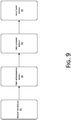
FIG. 9 is a schematic modular diagram of an apparatus for adjusting the number of component logical threads according to an example embodiment of the present disclosure. - The technical solutions in the example embodiments of the present disclosure will be clearly and completely described below with reference to the accompanying drawings in the example embodiments of the present disclosure. It is apparent that the example embodiments described merely represent some example embodiments rather than all example embodiments of the present disclosure. Based on the example embodiments in the present disclosure, all other example embodiments obtained by those of ordinary skill in the art without creative efforts should belong to the protection scope of the present disclosure.
- The present disclosure discloses a method for adjusting the number of component logical threads. As shown in
FIG. 1 , the method at least includes the following steps: - Step S11: A plurality of logical threads that is callable by a component is acquired.
- Step S12: A load state of each logical thread is determined according to a utilization rate of a data processing queue corresponding to each logical thread, the load state including a normal load state and an abnormal load state.
- In the example embodiment of the present disclosure, there is a data processing queue inside each logical thread. The data processing queue is used to store data that needs to be processed by the corresponding logical thread. In the example embodiment of the present disclosure, the data processing queue may be specifically as shown in
FIG. 2 , and the shaded portion represents occupied space that is already occupied by data stored in the processing queue. - In the example embodiment of the present disclosure, a utilization rate of a message queue = space occupied by data stored in the message queue / pre-allocated storage space of the message queue. Thus, a load state, i.e., a normal load state or an abnormal load state, of a corresponding logical thread may be determined according to a utilization rate of a message queue. The abnormal load state may specifically include a high load state with an excessively high utilization rate and a low load state with an excessively low utilization rate. In the high load state, the logical thread cannot ensure real-time processing of data. In the low load state, logical thread resources allocated to the component will be wasted.
- Step S13: whether the number of logical threads of the component needs to be adjusted is determined according to the load states of the logical threads of the component; if yes, step S14 is performed; otherwise, the procedure ends.
- In the example embodiment of the present disclosure, it may specifically be determined, according to a proportion of logical threads in the normal load state or the abnormal load state in all the logical threads that are callable by the component, whether the number of logical threads of a component needs to be adjusted. For example, if logical threads in the normal load state account for 80% of logical threads that may be called by a component, it may be determined that the number of logical threads of the component does not need to be adjusted. If logical threads in the abnormal load state account for 80%, it may be determined that the number of logical threads of the component needs to be adjusted.
- Step S14: The number of logical threads of the component is adjusted according to the determination result.
- In the example embodiment of the present disclosure, the number of logical threads of the component may be specifically adjusted to: the number of current logical threads of the component * the data amount of data sent by a sending apparatus per second / the data amount of data received by the component per second, the sending apparatus being an apparatus that sends data to the component.
- In the example embodiment of the present disclosure, a real-time computing program is generally composed of a Spout (message source) component and a Blot (message processing) component. A plurality of components may process data iteratively. As shown in
FIG. 3 , for example, a real-time computing program is composed of one Spout component and two Bolt components, and the two Bolt components are a first Bolt component and a second Bolt component respectively. In the example embodiment of the present disclosure, the Spout component may receive data sent from a message source, and call pre-allocated logical threads to process the data. Upon completion of the processing, the Spout component serves as an upstream component to send the data to the first Bolt component that serves as a downstream component. Likewise, upon completion of the data processing, the first Bolt component will serve as an upstream component to send the data to the second Bolt component that serves as a downstream component. In the example embodiment of the present disclosure, if the current component is a Spout component, the sending apparatus may be a message source device. If the current component is a Bolt component, the sending apparatus may be an upstream component of the current component. - As shown from the above technical solution that in the example embodiment of the present disclosure, first, a load state of each logical thread is determined according to a utilization rate of a data processing queue corresponding to each logical thread, the load state including a normal load state and an abnormal load state. Then, it is determined according to the load states of the logical threads of the component whether the number of logical threads of the component needs to be adjusted. Finally, the number of logical threads of the component is adjusted according to the determination result if the number of logical threads of the component needs to be adjusted. In the example embodiment of the present disclosure, the number of logical threads that may be called by a component may be adjusted according to load states of the logical threads, preventing logical threads that may be called by a component from being excessive or insufficient, thus improving the utilization rate of logical thread resources while ensuring real-time processing of data.
- In another feasible example embodiment of the present disclosure, as shown in
FIG. 4 , step S12 in all the foregoing example embodiments may include the following steps:
Step S41: whether a utilization rate of a data processing queue corresponding to a logical thread is greater than a first preset threshold is determined; if yes, step S42 is performed; otherwise, step S43 is performed. - In the example embodiment of the present disclosure, a user may set the value of the first preset threshold on his/her own as required. In a preferred example embodiment, the first preset threshold is 80%.
- Step S42: the logical thread is determined in a high load state.
- In the example embodiment of the present disclosure, when a utilization rate of a data processing queue corresponding to a logical thread is greater than the first preset threshold, it indicates that the logical thread has a large amount of data to be processed but fails to process the data in real time, and it is determined that the logical thread is in a high load state.
- Step S43: whether the utilization rate of the data processing queue corresponding to the current logical thread is less than a second preset threshold is determined; if yes, step S44 is performed; otherwise, step S45 is performed.
- In the example embodiment of the present disclosure, the user may also set the value of the second preset threshold on his/her own as required. In a preferred example embodiment, the second preset threshold is 20%.
- Step S44: the logical thread is determined in a low load state.
- In the example embodiment of the present disclosure, when a utilization rate of a data processing queue corresponding to a logical thread is less than the second preset threshold, it indicates that the logical thread is idle and wastes resources, and it is determined that the logical thread is in a low load state.
- Step S45: the logical thread is determined in a normal load state.
- In the example embodiment of the present disclosure, when a utilization rate of a data processing queue corresponding to a logical thread is greater than or equal to the second preset threshold and less than or equal to the first preset threshold, it indicates that the logical thread may process data normally, that is, the logical thread may ensure real-time processing of data without wasting resources. Thus, it is determined that the logical thread is in a normal load state.
- As shown from the above, by using the method in the example embodiment of the present disclosure, a load state of a logical thread may be determined, and then load states of all logical threads that may be called by a component may be determined.
- In another feasible example embodiment of the present disclosure, as shown in
FIG. 5 , step S13 in the all the foregoing example embodiments may include the following steps: - Step S51: The number of logical threads in the high load state and the number of logical threads in the low load state among all the logical threads that are callable by the component are counted respectively.
- Step S52: A high load probability and a low load probability of the component are calculated respectively by using a high load probability calculation formula and a low load probability calculation formula, the high load probability calculation formula = the number of logical threads in the high load state / the number of all the logical threads that are callable by the current component, and the low load probability calculation formula = the number of logical threads in the low load state / the number of all the logical threads that are callable by the current component.
- In the example embodiment of the present disclosure, in order to improve the accuracy, load states of all the logical threads in the current component may be collected at intervals of a preset time. After the load states of all the logical threads have been collected a preset number of times, the number of logical threads in the high load state and the number of logical threads in the low load state are counted. Then, a high load probability and a low load probability of the component are calculated by using the following calculation formulas: the high load probability calculation formula = the number of logical threads in the high load state / the number of all the logical threads that are callable by the current component * a preset number of times, and the low load probability calculation formula = the number of logical threads in the low load state / the number of all the logical threads that are callable by the current component * a preset number of times.
- Step S53: whether at least one of the high load probability and the low load probability of the component is greater than a third preset threshold is determined; if yes, step S54 is performed; otherwise, step S55 is performed.
- In the example embodiment of the present disclosure, the user may set the value of the third preset threshold on his/her own as required. In a preferred example embodiment, the third preset threshold may be set to 80%.
- In the example embodiment of the present disclosure, step S54 may be performed when the high load probability of the component is greater than the third preset threshold; or step S54 may be performed when the low load probability of the component is greater than the third preset threshold; or step S54 may be performed when both the high load probability and the low load probability of the component are greater than the third preset threshold.
- Step S54: the number of logical threads of the component that needs to be adjusted is determined.
- Step S55: the number of logical threads of the component that does not need to be adjusted is determined.
- As shown from the above, in the example embodiment of the present disclosure, whether the number of logical threads of a component needs to be adjusted is determined.
- In another feasible example embodiment of the present disclosure, the logical threads in all the foregoing example embodiments all run in an operational process. As shown in
FIG. 6 , the method in all the foregoing example embodiments may further include the following steps:
Step S61: logical threads need to be added or deleted for the component are determined according to the number of logical threads of the component that needs to be adjusted and the number of current logical threads. - In the example embodiment of the present disclosure, it is assumed that the number of logical threads of a component needs to be adjusted to 3 upon calculation by using the foregoing method, and the number of current logical threads of the component is 5. Then, it may be determined that two logical threads of the component need to be deleted currently.
- Step S62: whether logical threads are allowable to be added in an operational process associated with the current logical threads is determined, if the logical threads need to be added; if yes, step S63 is performed; otherwise, step S64 is performed.
- In the example embodiment of the present disclosure, the operational process associated with the current logical threads includes all operational processes in a computer cluster where the current logical threads are located.
- Step S63: The logical threads are added in the operational process associated with the current logical threads.
- Step S64: The number of operational processes that need to be added is determined.
- Step S65: Logical threads are deleted in the operational process if the corresponding logical threads need to be deleted.
- In the example embodiment of the present disclosure, all logical threads of a component are at the same level. Therefore, in the example embodiment of the present disclosure, the number of logical threads that need to be deleted may be determined according to a difference between the number of current logical threads of the component and the number of logical threads after adjustment. Then, a corresponding number of logical threads are deleted from the current component at random.
- It is thus clear that in the example embodiment of the present disclosure, logical threads of a current component may be specifically added or deleted.
- In another feasible example embodiment of the present disclosure, as shown in
FIG. 7 , step S62 in all the foregoing example embodiments may include the following steps:
Step S71: A plurality of operational processes associated with the current logical threads is determined. - In the example embodiment of the present disclosure, as stated above, the plurality of associated operational processes includes all operational processes in a computer cluster where the component is located.
- Step S72: The number of logical threads that is allowable to be added in each operational process is determined according to a preset increase formula, the increase formula being: the number of logical threads that is allowable to be added in the operational process = (total pre-allocated resources of the operational process / resources occupied by the operational process for running logical threads * a fourth preset value - 1) * the number of logical threads running in the current operational process.
- In the example embodiment of the present disclosure, the total pre-allocated resources of the operational process may be CPU resources or storage space pre-allocated to the operational process, and the resources occupied by the operational process for running logical threads may be CPU resources or storage space occupied by the operational process for running the logical threads.
- In the example embodiment of the present disclosure, the user may set the value of the third preset threshold on his/her own as required. In a preferred example embodiment, the third preset threshold may be set to 80%.
- Step S73: The total number of logical threads that is allowable to be added in all the associated operational processes is counted.
- In the example embodiment of the present disclosure, it is assumed that there are three operational processes in a computer cluster where the current component is located, which are a first operational process, a second operational process and a third operational process respectively, and it is determined by using the method provided in step S72 that two logical threads are allowable to be added to the first operational process, three logical threads are allowable to be added to the second operational process, and three logical threads are allowable to be added to the third operational process. Then, the total number of logical threads that is allowable to be added to the whole computer cluster is: 8 = 2 + 3 + 3.
- Step S74: whether the total number of logical threads that is allowable to be added is greater than or equal to the number of logical threads that need to be added for the component is determined; if yes, step S75 is performed; otherwise, step S76 is performed.
- Step S75: the logical threads are determined to be allowable to be added in the associated operational processes.
- Step S76: the logical threads are determined not to be allowable to be added in the associated operational processes.
- It is thus clear that in the example embodiment of the present disclosure, it may be determined whether to add logical threads that need to be added for a current component in operational processes associated with the current component.
- In still another feasible example embodiment of the present disclosure, as shown in
FIG. 8 , step S64 in all the foregoing example embodiments may include the following steps:
Step S81: The number Q of logical threads that is allowable to run in the associated operational processes under a preset load threshold is acquired. - In the example embodiment of the present disclosure, the preset load threshold may specifically be 80% of a load limit of the operational processes.
- Step S82: The number of operational processes that need to be added is calculated by using an operational process calculation formula, the operational process calculation formula being: the number of operational processes added = (N - T) /Q + 1, wherein N is the number of logical threads that need to be added for the component, T is the number of logical threads that is allowable to be added in the associated operational processes, and T, N and Q are positive integers.
- It is thus clear that the number of operational processes that need to be added may be determined by using the foregoing method.
- In still another feasible example embodiment of the present disclosure, when a first component and a second component transmit data, the method in all the foregoing example embodiments may further include:
- determining, at intervals of a preset time, first logical threads that are callable by an upstream component of a component and second logical threads that are callable by a downstream component; and
- establishing a communication connection between third logical threads that are callable by the current component and the first logical threads as well as a communication connection between the third logical threads and the second logical threads.
- As stated above, a component may include an upstream component and a downstream component. The number of logical threads that may be called by each component varies by using the method in the example embodiment of the present disclosure. Normal data transmission of logical threads between upstream and downstream components may be determined by using the method disclosed in the present disclosure.
- In still another feasible example embodiment of the present disclosure, the method in all the foregoing example embodiments may further include:
- determining sequentially whether any logical thread exists in each operational process associated with the current component; and
- deleting the operational process if no logical thread exists in the operational process.
- In the example embodiment of the present disclosure, when an operation of deleting logical threads is performed, it may cause an operational process to be empty of logical threads. In this case, the operational process does not execute any task. Resources occupied by the operational process may be released in time by using the method disclosed in the present disclosure.
- From the description of the method example embodiments above, those skilled in the art may clearly understand that the present disclosure may be implemented by software plus a necessary universal hardware platform, and certainly may also be implemented by hardware. However, the former is a preferred implementation under most circumstances. Based on such an understanding, the technical solutions of the present disclosure essentially or the part making contributions to the conventional techniques may be embodied in the form of a software product. The computer software product may be stored in a storage medium, and includes several instructions for instructing a computer device (which may be a personal computer, a server, a network device, or the like) to perform all or some of the steps of the methods described in the example embodiments of the present disclosure. The foregoing storage medium includes: any medium that may store program codes, such as a Read-Only Memory (ROM), a Random Access Memory (RAM), a magnetic disk, or an optical disc.
- Corresponding to the example embodiment of the method for adjusting the number of component logical threads provided in the present disclosure, the present disclosure further provides an apparatus for adjusting the number of component logical threads. As shown in
FIG. 9 , the apparatus includes: - an
acquisition module 91 configured to acquire a plurality of logical threads that is callable by a component; - a
first determination module 92 configured to determine a load state of each logical thread according to a utilization rate of a data processing queue corresponding to each logical thread, the load state including a normal load state and an abnormal load state; - a
first judgment module 93 configured to determine, according to the load states of the logical threads of the component, whether the number of logical threads of the component needs to be adjusted; and - an
adjustment module 94 configured to adjust the number of logical threads of the component according to the determination result if the number of logical threads of the component needs to be adjusted. - In the example embodiment of the present disclosure, the function of the
adjustment module 94 may be specifically implemented by an adjustment unit. The adjustment unit is configured to adjust the number of logical threads of the component to: the number of current logical threads of the component * the data amount of data sent by a sending apparatus per second / the data amount of data received by the component per second, the sending apparatus being an apparatus that sends data to the component. - A shown from the above technical solution, in the example embodiment of the present disclosure, first, a load state of each logical thread is determined according to a utilization rate of a data processing queue corresponding to each logical thread, the load state including a normal load state and an abnormal load state. Then, it is determined according to the load states of the logical threads of the component whether the number of logical threads of the component needs to be adjusted. Finally, the number of logical threads of the component is adjusted according to the determination result if the number of logical threads of the component needs to be adjusted. In the example embodiment of the present disclosure, the number of logical threads that may be called by a component may be adjusted according to load states of the logical threads, preventing logical threads that may be called by a component from being excessive or insufficient, thus improving the utilization rate of logical thread resources while ensuring real-time processing of data.
- In another feasible example embodiment of the present disclosure, the abnormal load state in all the foregoing example embodiments includes a high load state and a low load state, and the utilization rate is equal to space occupied by data stored in a message queue / pre-allocated storage space of the message queue; and the determination module includes:
- a first judgment unit configured to determine whether a utilization rate of a data processing queue corresponding to a logical thread is greater than a first preset threshold;
- a high load state determination unit configured to determine that the logical thread is in a high load state if the utilization rate is greater than the first preset threshold;
- a second judgment unit configured to determine whether the utilization rate of the data processing queue corresponding to the current logical thread is less than a second preset threshold if the utilization rate is not greater than the first preset threshold; and
- a low load state determination unit configured to determine that the logical thread is in a low load state if the utilization rate is less than the second preset threshold.
- It is thus clear that in the example embodiment of the present disclosure, a load state of a logical thread may be determined.
- In still another feasible example embodiment of the present disclosure, the judgment module in all the foregoing example embodiments includes:
- a first counting unit configured to respectively count the number of logical threads in the high load state and the number of logical threads in the low load state among all the logical threads that are callable by the component;
- a first calculation unit configured to calculate a high load probability and a low load probability of the component respectively by using a high load probability calculation formula and a low load probability calculation formula, the high load probability calculation formula = the number of logical threads in the high load state / the number of all the logical threads that are callable by the current component, and the low load probability calculation formula = the number of logical threads in the low load state / the number of all the logical threads that are callable by the current component;
- a third judgment unit configured to determine whether at least one of the high load probability and the low load probability of the component is greater than a third preset threshold; and
- a first determination unit configured to determine that the number of logical threads of the component needs to be adjusted if at least one of the high load probability and the low load probability of the component is greater than the third preset threshold.
- It is thus clear that in the example embodiment of the present disclosure, it may be determined whether the number of logical threads of a component needs to be adjusted.
- In still another feasible example embodiment of the present disclosure, the apparatus in all the foregoing example embodiments may further include:
- a second determination module configured to determine whether logical threads need to be added or deleted for the component according to the number of logical threads that the component needs to have after adjustment and the number of current logical threads;
- a second judgment module configured to determine whether logical threads are allowable to be added in an operational process associated with the current logical threads if the logical threads need to be added;
- an adding module configured to add the logical threads in the operational process associated with the current logical threads if the logical threads are allowable to be added in the operational process associated with the current logical threads;
- a third determination module configured to determine the number of operational processes that need to be added if the logical threads cannot be added in the operational process associated with the current logical threads; and
- a deletion module configured to delete logical threads in the operational process if the corresponding logical threads need to be deleted.
- It is thus clear that in the example embodiment of the present disclosure, logical threads are allowable to be added or deleted.
- In another feasible example embodiment of the present disclosure, the second judgment module in all the foregoing example embodiments includes:
- a second determination unit configured to determine a plurality of operational processes associated with the current logical threads;
- a third determination unit configured to determine, according to a preset increase formula, the number of logical threads that is allowable to be added in each operational process, the increase formula being: the number of logical threads that is allowable to be added in the operational process = (total pre-allocated resources of the operational process / resources occupied by the operational process for running logical threads * a fourth preset value - 1) * the number of logical threads running in the current operational process;
- a second counting unit configured to count the total number of logical threads that is allowable to be added in all the associated operational processes;
- a fourth judgment unit configured to determine whether the total number of logical threads that is allowable to be added is greater than or equal to the number of logical threads that need to be added for the component; and
- a third determination unit configured to determine that the logical threads are allowable to be added in the associated operational processes if the total number of logical threads that is allowable to be added is greater than or equal to the number of logical threads that need to be added for the component.
- It is thus clear that in the example embodiment of the present disclosure, it may be determined whether logical threads are allowable to be added in the associated operational processes.
- In another feasible example embodiment of the present disclosure, the third determination unit in all the foregoing example embodiments includes:
- an acquisition subunit configured to acquire the number Q of logical threads that is allowable to run in the associated operational processes under a preset load threshold; and
- a calculation subunit configured to calculate, by using an operational process calculation formula, the number of operational processes that need to be added, the operational process calculation formula being: the number of operational processes added = (N - T) /Q + 1, wherein N is the number of logical threads that need to be added for the component, T is the number of logical threads that is allowable to be added in the associated operational processes, and T, N and Q are positive integers.
- It is thus clear that in the example embodiment of the present disclosure, the number of newly added operational processes may be determined.
- In another feasible example embodiment of the present disclosure, the apparatus in all the foregoing example embodiments further includes:
- a fourth determination module configured to determine, at intervals of a preset time, first logical threads that are callable by an upstream component of a component and second logical threads that are callable by a downstream component; and
- an establishment module configured to establish a communication connection between third logical threads that are callable by the current component and the first logical threads as well as a communication connection between the third logical threads and the second logical threads.
- It is thus clear that in the example embodiment of the present disclosure, normal communication between upstream and downstream components may be ensured.
- In another feasible example embodiment of the present disclosure, the apparatus in all the foregoing example embodiments further includes:
- a third judgment module configured to determine sequentially whether any logical thread exists in each operational process associated with the current component; and
- a deletion module configured to delete the operational process if no logical thread exists in the operational process.
- It is thus clear that in the example embodiment of the present disclosure, an empty operational process may be deleted.
- It should be noted that in the text, the relation terms such as "first" and "second" are merely used to distinguish one entity or operation from another entity or operation, but do not necessarily require or imply such an actual relation or order between the entities or operations. Moreover, the terms "include", "comprise" or other variations thereof are intended to cover non-exclusive inclusion, so that a process, a method, an article or a device including a series of elements not only includes the elements, but also includes other elements not clearly listed, or further includes inherent elements of the process, method, article or device. In the absence of more limitations, an element defined by "including a/an..." does not exclude that the process, method, article or device including the element further has other identical elements.
- The above descriptions are merely specific implementations of the present disclosure, enabling those skilled in the art to understand or implement the present disclosure. A variety of modifications to the example embodiments will be obvious for those skilled in the art. General principles defined in this text may be implemented in other example embodiments without departing from the spirit or scope of the present disclosure. Therefore, the present disclosure will not be limited to the example embodiments shown in this text, and will be in line with the broadest scope consistent with the principles and novelties disclosed in this text.
Claims (18)
- A method for adjusting a number of logical threads of a component, the method comprising:acquiring a plurality of logical threads that is callable by a component;determining a load state of each logical thread according to a utilization rate of a data processing queue corresponding to each logical thread, the load state including a normal load state and an abnormal load state;determining, according to load states of the logical threads of the component, whether a number of logical threads of the component needs to be adjusted; andadjusting the number of logical threads of the component according to a result of the determining in response to determining that the number of logical threads of the component needs to be adjusted.
- The method of claim 1, wherein the adjusting the number of logical threads of the component according to the result of the determining comprises:
adjusting the number of logical threads of the component to be: a number of current logical threads of the component * amount of data sent by a sending apparatus per second / amount of data received by the component per second, the sending apparatus being an apparatus that sends data to the component. - The method of claim 1 or 2, wherein:the abnormal load state includes a high load state and a low load state;the utilization rate is equal to a space occupied by data stored in a message queue / a pre-allocated storage space of the message queue; andthe determining the load state of each logical thread according to the utilization rate of the data processing queue corresponding to each logical thread comprises:determining whether the utilization rate of the data processing queue corresponding to a logical thread is greater than a first preset threshold;determining that the logical thread is in the high load state in response to determining that the utilization rate is greater than the first preset threshold;determining whether the utilization rate of the data processing queue corresponding to the logical thread is less than a second preset threshold in response to determining that the utilization rate is not greater than the first preset threshold; anddetermining that the logical thread is in the low load state in response to determining that the utilization rate is less than the second preset threshold.
- The method of claim 3, wherein the determining, according to the load states of the logical threads of the component, whether the number of logical threads of the component needs to be adjusted comprises:respectively counting a number of logical threads in the high load state and a number of logical threads in the low load state among all the logical threads that are callable by the component;calculating a high load probability and a low load probability of the component by using a high load probability calculation formula and a low load probability calculation formula respectively, the high load probability calculation formula = the number of logical threads in the high load state / the number of all the logical threads that are callable by the component, and the low load probability calculation formula = the number of logical threads in the low load state / the number of all the logical threads that are callable by the component;determining whether at least one of the high load probability and the low load probability of the component is greater than a third preset threshold; anddetermining that the number of logical threads of the component needs to be adjusted in response to determining that at least one of the high load probability and the low load probability of the component is greater than the third preset threshold.
- The method of any of claims 1, 2 and 4, wherein:the logical threads run in an operational process; andthe method further comprises:determining whether the logical threads need to be added or deleted for the component according to the number of logical threads that needs to be adjusted for the component and the number of current logical threads;determining whether logical threads are allowable to be added in the operational process associated with the current logical threads in response to determining that the logical threads need to be added;adding the logical threads in the associated operational process in response to determining that the logical threads are allowable to be added in the operational process;determining a number of operational processes that need to be added in response to determining the logical threads that are not allowable to be added in the operational process; anddeleting logical threads in the operational process in response to determining that the corresponding logical threads need to be deleted.
- The method of claim 5, wherein the determining whether the logical threads are allowable to be added in the operational process associated with the current logical threads comprises:determining a plurality of operational processes associated with the current logical threads;determining, according to a preset increase formula, a number of logical threads that is allowable to be added in each operational process, the preset increase formula being a number of logical threads that is allowable to be added in the operational process = (total pre-allocated resources of the operational process / resources occupied by the operational process for running logical threads * a fourth preset value - 1) * a number of logical threads running in the current operational process;counting the total number of logical threads that is allowable to be added in all associated operational processes;determining whether the total number of logical threads that is allowable to be added is greater than or equal to the number of logical threads that need to be added for the component; anddetermining that the logical threads are allowable to be added in the associated operational processes in response to determining that the total number of logical threads that is allowable to be added is greater than or equal to the number of logical threads that need to be added for the component.
- The method of claim 6, wherein the determining the number of operational processes that need to be added comprises:acquiring a number Q of logical threads that is allowable to run in the associated operational processes under a preset load threshold; andcalculating, by using an operational process calculation formula, the number of operational processes that need to be added, the operational process calculation formula being a number of added operational processes = (N - T) /Q + 1, wherein N is a number of logical threads that need to be added for the component, T is the number of logical threads that is allowable to be added in the associated operational processes, and T, N and Q are positive integers.
- The method of any of claims 1, 2, 4, 6 and 7, further comprising:determining, at intervals of a preset time, first logical threads that are callable by an upstream component of the component and second logical threads that are callable by a downstream component of the component; andestablishing a communication connection between third logical threads that are callable by the component and the first logical threads as well as a communication connection between the third logical threads and the second logical threads.
- The method of any of claims 1, 2, 4, 6 and 7, further comprising:determining sequentially whether a logical thread exits in an operational process associated with the component; anddeleting the operational process in response to determining that no logical thread exists in the operational process.
- An apparatus for adjusting the number of component logical threads, the apparatus comprising:an acquisition module configured to acquire a plurality of logical threads that is callable by a component;a first determination module configured to determine a load state of each logical thread according to a utilization rate of a data processing queue corresponding to each logical thread, the load state including a normal load state and an abnormal load state;a first judgment module configured to determine, according to load states of the logical threads of the component, whether a number of logical threads of the component needs to be adjusted; andan adjustment module configured to adjust the number of logical threads of the component according to the result of determination result in response to determining that the number of logical threads of the component needs to be adjusted.
- The method of claim 10, wherein the adjustment module comprises:an adjustment unit configured to adjust the number of the logical threads of the component to a number of current logical threads of the component * amount of data sent by a sending apparatus per second / amount of data received by the component per second, the sending apparatus being an apparatus that sends data to the component.
- The apparatus of claim 10 or 11, wherein:the abnormal load state includes a high load state and a low load state;the utilization rate is equal to a space occupied by data stored in a message queue / a pre-allocated storage space of the message queue; andthe determination module comprises:a first determination unit configured to determine whether a utilization rate of a data processing queue corresponding to a logical thread is greater than a first preset threshold;a high load state determination unit configured to determine that the logical thread is in the high load state in response to determining that the utilization rate is greater than the first preset threshold;a second determination unit configured to determine whether the utilization rate of the data processing queue corresponding to the logical thread is less than a second preset threshold in response to determining that the utilization rate is not greater than the first preset threshold; anda low load state determination unit configured to determine that the logical thread is in the low load state in response to determining that the utilization rate is less than the second preset threshold.
- The apparatus of claim 12, wherein the judgment module comprises:a first counting unit configured to respectively count a number of logical threads in the high load state and a number of logical threads in the low load state among all the logical threads that are callable by the component;a first calculation unit configured to calculate a high load probability and a low load probability of the component by using a high load probability calculation formula and a low load probability calculation formula respectively, the high load probability calculation formula = the number of logical threads in the high load state / the number of all the logical threads that are callable by the component, and the low load probability calculation formula = the number of logical threads in the low load state / the number of all the logical threads that are callable by the component;a third determination unit configured to determine whether at least one of the high load probability and the low load probability of the component is greater than a third preset threshold; anda first determination unit configured to determine the number of logical threads of the component needs to be adjusted in response to determining that at least one of the high load probability and the low load probability of the component is greater than the third preset threshold.
- The method of any of claims 10, 11 and 13, wherein the apparatus further comprises:a second determination module configured to determine whether logical threads need to be added or deleted for the component according to the number of logical threads that the component needs to be adjusted and a number of current logical threads;a second judgment module configured to determine whether logical threads are allowable to be added in an operational process associated with the current logical threads in response to determining that the logical threads need to be added;an adding module configured to add the logical threads in the operational process associated with the current logical threads in response to determining that the logical threads are allowable to be added in the operational process associated with the current logical threads;a third determination module configured to determine a number of operational processes that need to be added in response to determining that the logical threads are not allowable to be added in the operational process associated with the current logical threads; anda deletion module configured to delete logical threads in the operational process in response to determining that the corresponding logical threads need to be deleted.
- The apparatus of claim 14, wherein the second judgment module comprises:a second determination unit configured to determine a plurality of operational processes associated with the current logical threads;a third determination unit configured to determine, according to a preset increase formula, a number of logical threads that is allowable to be added in each operational process, the increase formula being: the number of logical threads that is allowable to be added in the operational process = (total pre-allocated resources of the operational process / resources occupied by the operational process for running logical threads * a fourth preset value - 1) * the number of logical threads running in the current operational process;a second counting unit configured to count the total number of logical threads that is allowable to be added in all the associated operational processes;a fourth judgment unit configured to determine whether the total number of logical threads that is allowable to be added is greater than or equal to the number of logical threads that need to be added for the component; anda third determination unit configured to determine that the logical threads are allowable to be added in the associated operational processes in response to determining that the total number of logical threads that is allowable to be added is greater than or equal to the number of logical threads that need to be added for the component.
- The apparatus of claim 15, wherein the third determination unit comprises:an acquisition subunit configured to acquire a number Q of logical threads that is allowable to run in the associated operational processes under a preset load threshold; anda calculation subunit configured to calculate, by using an operational process calculation formula, the number of operational processes that need to be added, the operational process calculation formula being a number of added operational processes = (N - T) /Q + 1, wherein N is the number of logical threads that need to be added for the component, T is the number of logical threads that is allowable to be added in the associated operational processes, and T, N and Q are positive integers.
- The apparatus of any of claims 10, 11, 13, 15 and 16, wherein the apparatus further comprises:a fourth determination module configured to determine, at intervals of a preset time, first logical threads that are callable by an upstream component of the component and second logical threads that are callable by a downstream component of the component; andan establishment module configured to establish a communication connection between third logical threads that are callable by the component and the first logical threads as well as a communication connection between the third logical threads and the second logical threads.
- The apparatus of any of claims 10, 11, 13, 15 and 16, wherein the apparatus further comprises:a third determination module configured to determining sequentially whether a logical thread exits in an operational process associated with the component; anda deleting module configured to delete the operational process in response to determining that no logical thread exists in the operational process.
Applications Claiming Priority (2)
| Application Number | Priority Date | Filing Date | Title |
|---|---|---|---|
| CN201511021180.2A CN106933673B (en) | 2015-12-30 | 2015-12-30 | Method and device for adjusting number of logical threads of component |
| PCT/CN2016/110251 WO2017114180A1 (en) | 2015-12-30 | 2016-12-16 | Component logical threads quantity adjustment method and device |
Publications (3)
| Publication Number | Publication Date |
|---|---|
| EP3399413A1 true EP3399413A1 (en) | 2018-11-07 |
| EP3399413A4 EP3399413A4 (en) | 2019-08-07 |
| EP3399413B1 EP3399413B1 (en) | 2021-05-05 |
Family
ID=59225931
Family Applications (1)
| Application Number | Title | Priority Date | Filing Date |
|---|---|---|---|
| EP16880970.5A Active EP3399413B1 (en) | 2015-12-30 | 2016-12-16 | Component logical threads quantity adjustment method and device |
Country Status (5)
| Country | Link |
|---|---|
| US (1) | US10783005B2 (en) |
| EP (1) | EP3399413B1 (en) |
| JP (1) | JP2019500700A (en) |
| CN (1) | CN106933673B (en) |
| WO (1) | WO2017114180A1 (en) |
Families Citing this family (6)
| Publication number | Priority date | Publication date | Assignee | Title |
|---|---|---|---|---|
| CN108897876A (en) * | 2018-06-29 | 2018-11-27 | 中科鼎富(北京)科技发展有限公司 | A kind of data cut-in method and device |
| CN113138772B (en) * | 2020-01-19 | 2023-12-05 | 北京京东振世信息技术有限公司 | Construction method and device of data processing platform, electronic equipment and storage medium |
| US11467877B2 (en) | 2020-01-31 | 2022-10-11 | Salesforce, Inc. | Throttling and limiting thread resources of service computing platform |
| CN112631754B (en) * | 2020-12-29 | 2025-01-10 | 浙江大华技术股份有限公司 | Data processing method, device, storage medium and electronic device |
| KR102307641B1 (en) * | 2021-04-30 | 2021-10-01 | 나무기술 주식회사 | Parallel processing control system for cloud operation data analysis |
| CN115883665A (en) * | 2022-11-30 | 2023-03-31 | 广东亿迅科技有限公司 | A method and system for dynamically adjusting the concurrency of pushing graphs |
Family Cites Families (15)
| Publication number | Priority date | Publication date | Assignee | Title |
|---|---|---|---|---|
| US7237242B2 (en) * | 2002-12-31 | 2007-06-26 | International Business Machines Corporation | Dynamic thread pool tuning techniques |
| US7162571B2 (en) * | 2003-12-09 | 2007-01-09 | Emc Corporation | Methods and apparatus for parsing a content address to facilitate selection of a physical storage location in a data storage system |
| US7681196B2 (en) * | 2004-11-18 | 2010-03-16 | Oracle International Corporation | Providing optimal number of threads to applications performing multi-tasking using threads |
| CA2620337C (en) * | 2008-02-04 | 2012-11-27 | Omnivex Corporation | Digital signage network |
| CN100562854C (en) * | 2008-03-11 | 2009-11-25 | 浙江大学 | Implementation method of multi-core processor operating system load balancing |
| US8631415B1 (en) * | 2009-08-25 | 2014-01-14 | Netapp, Inc. | Adjustment of threads for execution based on over-utilization of a domain in a multi-processor system by sub-dividing parallizable group of threads to sub-domains |
| JP5531679B2 (en) * | 2010-03-04 | 2014-06-25 | 日本電気株式会社 | Power consumption reduction method, power consumption reduction device, and power consumption reduction program for information processing apparatus having SMT compatible CPU |
| JP5843459B2 (en) * | 2011-03-30 | 2016-01-13 | インターナショナル・ビジネス・マシーンズ・コーポレーションInternational Business Machines Corporation | Information processing system, information processing apparatus, scaling method, program, and recording medium |
| CN102591721A (en) * | 2011-12-30 | 2012-07-18 | 北京新媒传信科技有限公司 | Method and system for distributing thread execution task |
| CN102866922B (en) * | 2012-08-31 | 2014-10-22 | 河海大学 | A Load Balancing Method in Multi-thread Parallel Processing of Massive Data |
| CN103677997B (en) * | 2012-09-21 | 2017-04-12 | 宏达国际电子股份有限公司 | Multi-core device and multi-thread scheduling method thereof |
| WO2015069222A1 (en) * | 2013-11-05 | 2015-05-14 | Hewlett Packard Development Company, L.P. | Forum inspection based on correlation rating of response poster |
| WO2015071008A1 (en) * | 2013-11-14 | 2015-05-21 | Alcatel Lucent | Distributed computing unit, system and respective method |
| JP6237318B2 (en) * | 2014-02-19 | 2017-11-29 | 富士通株式会社 | Management device, workload distribution management method, and workload distribution management program |
| US9722945B2 (en) * | 2014-03-31 | 2017-08-01 | Microsoft Technology Licensing, Llc | Dynamically identifying target capacity when scaling cloud resources |
-
2015
- 2015-12-30 CN CN201511021180.2A patent/CN106933673B/en active Active
-
2016
- 2016-12-16 JP JP2018534546A patent/JP2019500700A/en active Pending
- 2016-12-16 WO PCT/CN2016/110251 patent/WO2017114180A1/en not_active Ceased
- 2016-12-16 EP EP16880970.5A patent/EP3399413B1/en active Active
-
2018
- 2018-06-29 US US16/024,539 patent/US10783005B2/en active Active
Also Published As
| Publication number | Publication date |
|---|---|
| CN106933673A (en) | 2017-07-07 |
| WO2017114180A1 (en) | 2017-07-06 |
| EP3399413A4 (en) | 2019-08-07 |
| US10783005B2 (en) | 2020-09-22 |
| US20180307536A1 (en) | 2018-10-25 |
| CN106933673B (en) | 2020-11-27 |
| JP2019500700A (en) | 2019-01-10 |
| EP3399413B1 (en) | 2021-05-05 |
Similar Documents
| Publication | Publication Date | Title |
|---|---|---|
| EP3399413A1 (en) | Component logical threads quantity adjustment method and device | |
| CN108874640B (en) | Cluster performance evaluation method and device | |
| CN108776934B (en) | Distributed data calculation method and device, computer equipment and readable storage medium | |
| CN111008075A (en) | Load balancing system, method, device, equipment and medium | |
| CN114448989B (en) | Method, device, electronic equipment, storage medium and product for adjusting message distribution | |
| CN111970339B (en) | Request control method and device and electronic equipment | |
| CN109428926B (en) | A method and apparatus for scheduling task nodes | |
| CN112887407A (en) | Job flow control method and device for distributed cluster | |
| CN111625370B (en) | A message push method, device, electronic device and storage medium | |
| CN113347238A (en) | Message partitioning method, system, device and storage medium based on block chain | |
| CN118939184A (en) | A real-time control method and device for the number of Kafka cluster copies | |
| CN108234658B (en) | Method and device for sensing health condition of server cluster and server | |
| EP4155969B1 (en) | Query processing method and apparatus, electronic device and storage medium | |
| CN118158224A (en) | A network load balancing method, product, device and medium | |
| CN110955579A (en) | Ambari-based large data platform monitoring method | |
| CN114138452B (en) | High-energy-efficiency computing node selection method and device in edge computing | |
| CN113360736B (en) | Internet data capturing method and device | |
| CN116627615A (en) | Task processing method and device, electronic equipment and storage medium | |
| CN111881139B (en) | Data acquisition method, system, equipment and readable storage medium | |
| EP4066117B1 (en) | Managing provenance information for data processing pipelines | |
| CN108055337A (en) | The method and apparatus that multiple service platform docks public platform | |
| TW201828049A (en) | Method and device to adjust the number of component logic Threads to increase the utilization rate of resource under the premise ensuring the real-time calculation of data | |
| CN117294578B (en) | A communication method, system, computer equipment and storage medium | |
| CN117082083B (en) | Data storage method, device and medium based on distributed Internet of things architecture | |
| CN114328139A (en) | Monitoring method and device for hall interface, storage medium and server |
Legal Events
| Date | Code | Title | Description |
|---|---|---|---|
| STAA | Information on the status of an ep patent application or granted ep patent |
Free format text: STATUS: THE INTERNATIONAL PUBLICATION HAS BEEN MADE |
|
| PUAI | Public reference made under article 153(3) epc to a published international application that has entered the european phase |
Free format text: ORIGINAL CODE: 0009012 |
|
| STAA | Information on the status of an ep patent application or granted ep patent |
Free format text: STATUS: REQUEST FOR EXAMINATION WAS MADE |
|
| 17P | Request for examination filed |
Effective date: 20180625 |
|
| AK | Designated contracting states |
Kind code of ref document: A1 Designated state(s): AL AT BE BG CH CY CZ DE DK EE ES FI FR GB GR HR HU IE IS IT LI LT LU LV MC MK MT NL NO PL PT RO RS SE SI SK SM TR |
|
| AX | Request for extension of the european patent |
Extension state: BA ME |
|
| DAV | Request for validation of the european patent (deleted) | ||
| DAX | Request for extension of the european patent (deleted) | ||
| A4 | Supplementary search report drawn up and despatched |
Effective date: 20190708 |
|
| RIC1 | Information provided on ipc code assigned before grant |
Ipc: G06F 9/50 20060101AFI20190702BHEP |
|
| STAA | Information on the status of an ep patent application or granted ep patent |
Free format text: STATUS: EXAMINATION IS IN PROGRESS |
|
| 17Q | First examination report despatched |
Effective date: 20200430 |
|
| GRAP | Despatch of communication of intention to grant a patent |
Free format text: ORIGINAL CODE: EPIDOSNIGR1 |
|
| STAA | Information on the status of an ep patent application or granted ep patent |
Free format text: STATUS: GRANT OF PATENT IS INTENDED |
|
| INTG | Intention to grant announced |
Effective date: 20201209 |
|
| GRAS | Grant fee paid |
Free format text: ORIGINAL CODE: EPIDOSNIGR3 |
|
| GRAA | (expected) grant |
Free format text: ORIGINAL CODE: 0009210 |
|
| STAA | Information on the status of an ep patent application or granted ep patent |
Free format text: STATUS: THE PATENT HAS BEEN GRANTED |
|
| AK | Designated contracting states |
Kind code of ref document: B1 Designated state(s): AL AT BE BG CH CY CZ DE DK EE ES FI FR GB GR HR HU IE IS IT LI LT LU LV MC MK MT NL NO PL PT RO RS SE SI SK SM TR |
|
| REG | Reference to a national code |
Ref country code: GB Ref legal event code: FG4D |
|
| REG | Reference to a national code |
Ref country code: CH Ref legal event code: EP |
|
| REG | Reference to a national code |
Ref country code: AT Ref legal event code: REF Ref document number: 1390657 Country of ref document: AT Kind code of ref document: T Effective date: 20210515 |
|
| REG | Reference to a national code |
Ref country code: IE Ref legal event code: FG4D |
|
| REG | Reference to a national code |
Ref country code: DE Ref legal event code: R096 Ref document number: 602016057592 Country of ref document: DE |
|
| REG | Reference to a national code |
Ref country code: LT Ref legal event code: MG9D |
|
| REG | Reference to a national code |
Ref country code: AT Ref legal event code: MK05 Ref document number: 1390657 Country of ref document: AT Kind code of ref document: T Effective date: 20210505 |
|
| PG25 | Lapsed in a contracting state [announced via postgrant information from national office to epo] |
Ref country code: BG Free format text: LAPSE BECAUSE OF FAILURE TO SUBMIT A TRANSLATION OF THE DESCRIPTION OR TO PAY THE FEE WITHIN THE PRESCRIBED TIME-LIMIT Effective date: 20210805 Ref country code: AT Free format text: LAPSE BECAUSE OF FAILURE TO SUBMIT A TRANSLATION OF THE DESCRIPTION OR TO PAY THE FEE WITHIN THE PRESCRIBED TIME-LIMIT Effective date: 20210505 Ref country code: HR Free format text: LAPSE BECAUSE OF FAILURE TO SUBMIT A TRANSLATION OF THE DESCRIPTION OR TO PAY THE FEE WITHIN THE PRESCRIBED TIME-LIMIT Effective date: 20210505 Ref country code: LT Free format text: LAPSE BECAUSE OF FAILURE TO SUBMIT A TRANSLATION OF THE DESCRIPTION OR TO PAY THE FEE WITHIN THE PRESCRIBED TIME-LIMIT Effective date: 20210505 Ref country code: FI Free format text: LAPSE BECAUSE OF FAILURE TO SUBMIT A TRANSLATION OF THE DESCRIPTION OR TO PAY THE FEE WITHIN THE PRESCRIBED TIME-LIMIT Effective date: 20210505 |
|
| PG25 | Lapsed in a contracting state [announced via postgrant information from national office to epo] |
Ref country code: LV Free format text: LAPSE BECAUSE OF FAILURE TO SUBMIT A TRANSLATION OF THE DESCRIPTION OR TO PAY THE FEE WITHIN THE PRESCRIBED TIME-LIMIT Effective date: 20210505 Ref country code: GR Free format text: LAPSE BECAUSE OF FAILURE TO SUBMIT A TRANSLATION OF THE DESCRIPTION OR TO PAY THE FEE WITHIN THE PRESCRIBED TIME-LIMIT Effective date: 20210806 Ref country code: IS Free format text: LAPSE BECAUSE OF FAILURE TO SUBMIT A TRANSLATION OF THE DESCRIPTION OR TO PAY THE FEE WITHIN THE PRESCRIBED TIME-LIMIT Effective date: 20210905 Ref country code: PL Free format text: LAPSE BECAUSE OF FAILURE TO SUBMIT A TRANSLATION OF THE DESCRIPTION OR TO PAY THE FEE WITHIN THE PRESCRIBED TIME-LIMIT Effective date: 20210505 Ref country code: NO Free format text: LAPSE BECAUSE OF FAILURE TO SUBMIT A TRANSLATION OF THE DESCRIPTION OR TO PAY THE FEE WITHIN THE PRESCRIBED TIME-LIMIT Effective date: 20210805 Ref country code: PT Free format text: LAPSE BECAUSE OF FAILURE TO SUBMIT A TRANSLATION OF THE DESCRIPTION OR TO PAY THE FEE WITHIN THE PRESCRIBED TIME-LIMIT Effective date: 20210906 Ref country code: SE Free format text: LAPSE BECAUSE OF FAILURE TO SUBMIT A TRANSLATION OF THE DESCRIPTION OR TO PAY THE FEE WITHIN THE PRESCRIBED TIME-LIMIT Effective date: 20210505 Ref country code: RS Free format text: LAPSE BECAUSE OF FAILURE TO SUBMIT A TRANSLATION OF THE DESCRIPTION OR TO PAY THE FEE WITHIN THE PRESCRIBED TIME-LIMIT Effective date: 20210505 |
|
| REG | Reference to a national code |
Ref country code: NL Ref legal event code: MP Effective date: 20210505 |
|
| PG25 | Lapsed in a contracting state [announced via postgrant information from national office to epo] |
Ref country code: NL Free format text: LAPSE BECAUSE OF FAILURE TO SUBMIT A TRANSLATION OF THE DESCRIPTION OR TO PAY THE FEE WITHIN THE PRESCRIBED TIME-LIMIT Effective date: 20210505 |
|
| PG25 | Lapsed in a contracting state [announced via postgrant information from national office to epo] |
Ref country code: EE Free format text: LAPSE BECAUSE OF FAILURE TO SUBMIT A TRANSLATION OF THE DESCRIPTION OR TO PAY THE FEE WITHIN THE PRESCRIBED TIME-LIMIT Effective date: 20210505 Ref country code: DK Free format text: LAPSE BECAUSE OF FAILURE TO SUBMIT A TRANSLATION OF THE DESCRIPTION OR TO PAY THE FEE WITHIN THE PRESCRIBED TIME-LIMIT Effective date: 20210505 Ref country code: CZ Free format text: LAPSE BECAUSE OF FAILURE TO SUBMIT A TRANSLATION OF THE DESCRIPTION OR TO PAY THE FEE WITHIN THE PRESCRIBED TIME-LIMIT Effective date: 20210505 Ref country code: RO Free format text: LAPSE BECAUSE OF FAILURE TO SUBMIT A TRANSLATION OF THE DESCRIPTION OR TO PAY THE FEE WITHIN THE PRESCRIBED TIME-LIMIT Effective date: 20210505 Ref country code: ES Free format text: LAPSE BECAUSE OF FAILURE TO SUBMIT A TRANSLATION OF THE DESCRIPTION OR TO PAY THE FEE WITHIN THE PRESCRIBED TIME-LIMIT Effective date: 20210505 Ref country code: SM Free format text: LAPSE BECAUSE OF FAILURE TO SUBMIT A TRANSLATION OF THE DESCRIPTION OR TO PAY THE FEE WITHIN THE PRESCRIBED TIME-LIMIT Effective date: 20210505 Ref country code: SK Free format text: LAPSE BECAUSE OF FAILURE TO SUBMIT A TRANSLATION OF THE DESCRIPTION OR TO PAY THE FEE WITHIN THE PRESCRIBED TIME-LIMIT Effective date: 20210505 |
|
| REG | Reference to a national code |
Ref country code: DE Ref legal event code: R097 Ref document number: 602016057592 Country of ref document: DE |
|
| PLBE | No opposition filed within time limit |
Free format text: ORIGINAL CODE: 0009261 |
|
| STAA | Information on the status of an ep patent application or granted ep patent |
Free format text: STATUS: NO OPPOSITION FILED WITHIN TIME LIMIT |
|
| 26N | No opposition filed |
Effective date: 20220208 |
|
| PG25 | Lapsed in a contracting state [announced via postgrant information from national office to epo] |
Ref country code: IS Free format text: LAPSE BECAUSE OF FAILURE TO SUBMIT A TRANSLATION OF THE DESCRIPTION OR TO PAY THE FEE WITHIN THE PRESCRIBED TIME-LIMIT Effective date: 20210905 Ref country code: AL Free format text: LAPSE BECAUSE OF FAILURE TO SUBMIT A TRANSLATION OF THE DESCRIPTION OR TO PAY THE FEE WITHIN THE PRESCRIBED TIME-LIMIT Effective date: 20210505 |
|
| PG25 | Lapsed in a contracting state [announced via postgrant information from national office to epo] |
Ref country code: MC Free format text: LAPSE BECAUSE OF FAILURE TO SUBMIT A TRANSLATION OF THE DESCRIPTION OR TO PAY THE FEE WITHIN THE PRESCRIBED TIME-LIMIT Effective date: 20210505 Ref country code: IT Free format text: LAPSE BECAUSE OF FAILURE TO SUBMIT A TRANSLATION OF THE DESCRIPTION OR TO PAY THE FEE WITHIN THE PRESCRIBED TIME-LIMIT Effective date: 20210505 |
|
| REG | Reference to a national code |
Ref country code: CH Ref legal event code: PL |
|
| REG | Reference to a national code |
Ref country code: BE Ref legal event code: MM Effective date: 20211231 |
|
| PG25 | Lapsed in a contracting state [announced via postgrant information from national office to epo] |
Ref country code: LU Free format text: LAPSE BECAUSE OF NON-PAYMENT OF DUE FEES Effective date: 20211216 Ref country code: IE Free format text: LAPSE BECAUSE OF NON-PAYMENT OF DUE FEES Effective date: 20211216 |
|
| PG25 | Lapsed in a contracting state [announced via postgrant information from national office to epo] |
Ref country code: BE Free format text: LAPSE BECAUSE OF NON-PAYMENT OF DUE FEES Effective date: 20211231 |
|
| PG25 | Lapsed in a contracting state [announced via postgrant information from national office to epo] |
Ref country code: LI Free format text: LAPSE BECAUSE OF NON-PAYMENT OF DUE FEES Effective date: 20211231 Ref country code: CH Free format text: LAPSE BECAUSE OF NON-PAYMENT OF DUE FEES Effective date: 20211231 |
|
| P01 | Opt-out of the competence of the unified patent court (upc) registered |
Effective date: 20230418 |
|
| PG25 | Lapsed in a contracting state [announced via postgrant information from national office to epo] |
Ref country code: CY Free format text: LAPSE BECAUSE OF FAILURE TO SUBMIT A TRANSLATION OF THE DESCRIPTION OR TO PAY THE FEE WITHIN THE PRESCRIBED TIME-LIMIT Effective date: 20210505 |
|
| PG25 | Lapsed in a contracting state [announced via postgrant information from national office to epo] |
Ref country code: HU Free format text: LAPSE BECAUSE OF FAILURE TO SUBMIT A TRANSLATION OF THE DESCRIPTION OR TO PAY THE FEE WITHIN THE PRESCRIBED TIME-LIMIT; INVALID AB INITIO Effective date: 20161216 |
|
| PG25 | Lapsed in a contracting state [announced via postgrant information from national office to epo] |
Ref country code: MK Free format text: LAPSE BECAUSE OF FAILURE TO SUBMIT A TRANSLATION OF THE DESCRIPTION OR TO PAY THE FEE WITHIN THE PRESCRIBED TIME-LIMIT Effective date: 20210505 |
|
| PG25 | Lapsed in a contracting state [announced via postgrant information from national office to epo] |
Ref country code: MT Free format text: LAPSE BECAUSE OF FAILURE TO SUBMIT A TRANSLATION OF THE DESCRIPTION OR TO PAY THE FEE WITHIN THE PRESCRIBED TIME-LIMIT Effective date: 20210505 |
|
| PG25 | Lapsed in a contracting state [announced via postgrant information from national office to epo] |
Ref country code: TR Free format text: LAPSE BECAUSE OF FAILURE TO SUBMIT A TRANSLATION OF THE DESCRIPTION OR TO PAY THE FEE WITHIN THE PRESCRIBED TIME-LIMIT Effective date: 20210505 |
|
| PGFP | Annual fee paid to national office [announced via postgrant information from national office to epo] |
Ref country code: DE Payment date: 20251212 Year of fee payment: 10 |
|
| PGFP | Annual fee paid to national office [announced via postgrant information from national office to epo] |
Ref country code: GB Payment date: 20251211 Year of fee payment: 10 |
|
| PGFP | Annual fee paid to national office [announced via postgrant information from national office to epo] |
Ref country code: FR Payment date: 20251212 Year of fee payment: 10 |