EP3399361A1 - Head-mounted display device and control method therefor - Google Patents
Head-mounted display device and control method therefor Download PDFInfo
- Publication number
- EP3399361A1 EP3399361A1 EP15911817.3A EP15911817A EP3399361A1 EP 3399361 A1 EP3399361 A1 EP 3399361A1 EP 15911817 A EP15911817 A EP 15911817A EP 3399361 A1 EP3399361 A1 EP 3399361A1
- Authority
- EP
- European Patent Office
- Prior art keywords
- head
- signal
- touch
- audio
- processor
- Prior art date
- Legal status (The legal status is an assumption and is not a legal conclusion. Google has not performed a legal analysis and makes no representation as to the accuracy of the status listed.)
- Withdrawn
Links
Images


Classifications
-
- G—PHYSICS
- G02—OPTICS
- G02B—OPTICAL ELEMENTS, SYSTEMS OR APPARATUS
- G02B27/00—Optical systems or apparatus not provided for by any of the groups G02B1/00 - G02B26/00, G02B30/00
- G02B27/01—Head-up displays
- G02B27/017—Head mounted
- G02B27/0176—Head mounted characterised by mechanical features
-
- G—PHYSICS
- G02—OPTICS
- G02B—OPTICAL ELEMENTS, SYSTEMS OR APPARATUS
- G02B27/00—Optical systems or apparatus not provided for by any of the groups G02B1/00 - G02B26/00, G02B30/00
- G02B27/01—Head-up displays
- G02B27/017—Head mounted
-
- G—PHYSICS
- G02—OPTICS
- G02B—OPTICAL ELEMENTS, SYSTEMS OR APPARATUS
- G02B27/00—Optical systems or apparatus not provided for by any of the groups G02B1/00 - G02B26/00, G02B30/00
- G02B27/01—Head-up displays
- G02B27/017—Head mounted
- G02B27/0172—Head mounted characterised by optical features
-
- G—PHYSICS
- G06—COMPUTING OR CALCULATING; COUNTING
- G06F—ELECTRIC DIGITAL DATA PROCESSING
- G06F1/00—Details not covered by groups G06F3/00 - G06F13/00 and G06F21/00
- G06F1/16—Constructional details or arrangements
- G06F1/1613—Constructional details or arrangements for portable computers
- G06F1/163—Wearable computers, e.g. on a belt
-
- G—PHYSICS
- G06—COMPUTING OR CALCULATING; COUNTING
- G06F—ELECTRIC DIGITAL DATA PROCESSING
- G06F3/00—Input arrangements for transferring data to be processed into a form capable of being handled by the computer; Output arrangements for transferring data from processing unit to output unit, e.g. interface arrangements
- G06F3/01—Input arrangements or combined input and output arrangements for interaction between user and computer
- G06F3/011—Arrangements for interaction with the human body, e.g. for user immersion in virtual reality
-
- G—PHYSICS
- G06—COMPUTING OR CALCULATING; COUNTING
- G06F—ELECTRIC DIGITAL DATA PROCESSING
- G06F3/00—Input arrangements for transferring data to be processed into a form capable of being handled by the computer; Output arrangements for transferring data from processing unit to output unit, e.g. interface arrangements
- G06F3/01—Input arrangements or combined input and output arrangements for interaction between user and computer
- G06F3/03—Arrangements for converting the position or the displacement of a member into a coded form
- G06F3/041—Digitisers, e.g. for touch screens or touch pads, characterised by the transducing means
-
- G—PHYSICS
- G06—COMPUTING OR CALCULATING; COUNTING
- G06F—ELECTRIC DIGITAL DATA PROCESSING
- G06F3/00—Input arrangements for transferring data to be processed into a form capable of being handled by the computer; Output arrangements for transferring data from processing unit to output unit, e.g. interface arrangements
- G06F3/01—Input arrangements or combined input and output arrangements for interaction between user and computer
- G06F3/03—Arrangements for converting the position or the displacement of a member into a coded form
- G06F3/041—Digitisers, e.g. for touch screens or touch pads, characterised by the transducing means
- G06F3/047—Digitisers, e.g. for touch screens or touch pads, characterised by the transducing means using sets of wires, e.g. crossed wires
-
- G—PHYSICS
- G06—COMPUTING OR CALCULATING; COUNTING
- G06F—ELECTRIC DIGITAL DATA PROCESSING
- G06F3/00—Input arrangements for transferring data to be processed into a form capable of being handled by the computer; Output arrangements for transferring data from processing unit to output unit, e.g. interface arrangements
- G06F3/01—Input arrangements or combined input and output arrangements for interaction between user and computer
- G06F3/048—Interaction techniques based on graphical user interfaces [GUI]
- G06F3/0487—Interaction techniques based on graphical user interfaces [GUI] using specific features provided by the input device, e.g. functions controlled by the rotation of a mouse with dual sensing arrangements, or of the nature of the input device, e.g. tap gestures based on pressure sensed by a digitiser
- G06F3/0488—Interaction techniques based on graphical user interfaces [GUI] using specific features provided by the input device, e.g. functions controlled by the rotation of a mouse with dual sensing arrangements, or of the nature of the input device, e.g. tap gestures based on pressure sensed by a digitiser using a touch-screen or digitiser, e.g. input of commands through traced gestures
-
- G—PHYSICS
- G06—COMPUTING OR CALCULATING; COUNTING
- G06F—ELECTRIC DIGITAL DATA PROCESSING
- G06F3/00—Input arrangements for transferring data to be processed into a form capable of being handled by the computer; Output arrangements for transferring data from processing unit to output unit, e.g. interface arrangements
- G06F3/01—Input arrangements or combined input and output arrangements for interaction between user and computer
- G06F3/048—Interaction techniques based on graphical user interfaces [GUI]
- G06F3/0487—Interaction techniques based on graphical user interfaces [GUI] using specific features provided by the input device, e.g. functions controlled by the rotation of a mouse with dual sensing arrangements, or of the nature of the input device, e.g. tap gestures based on pressure sensed by a digitiser
- G06F3/0488—Interaction techniques based on graphical user interfaces [GUI] using specific features provided by the input device, e.g. functions controlled by the rotation of a mouse with dual sensing arrangements, or of the nature of the input device, e.g. tap gestures based on pressure sensed by a digitiser using a touch-screen or digitiser, e.g. input of commands through traced gestures
- G06F3/04883—Interaction techniques based on graphical user interfaces [GUI] using specific features provided by the input device, e.g. functions controlled by the rotation of a mouse with dual sensing arrangements, or of the nature of the input device, e.g. tap gestures based on pressure sensed by a digitiser using a touch-screen or digitiser, e.g. input of commands through traced gestures for inputting data by handwriting, e.g. gesture or text
-
- H—ELECTRICITY
- H04—ELECTRIC COMMUNICATION TECHNIQUE
- H04R—LOUDSPEAKERS, MICROPHONES, GRAMOPHONE PICK-UPS OR LIKE ACOUSTIC ELECTROMECHANICAL TRANSDUCERS; ELECTRIC HEARING AIDS; PUBLIC ADDRESS SYSTEMS
- H04R5/00—Stereophonic arrangements
- H04R5/033—Headphones for stereophonic communication
-
- G—PHYSICS
- G02—OPTICS
- G02B—OPTICAL ELEMENTS, SYSTEMS OR APPARATUS
- G02B27/00—Optical systems or apparatus not provided for by any of the groups G02B1/00 - G02B26/00, G02B30/00
- G02B27/01—Head-up displays
- G02B27/0101—Head-up displays characterised by optical features
- G02B2027/014—Head-up displays characterised by optical features comprising information/image processing systems
-
- G—PHYSICS
- G06—COMPUTING OR CALCULATING; COUNTING
- G06F—ELECTRIC DIGITAL DATA PROCESSING
- G06F3/00—Input arrangements for transferring data to be processed into a form capable of being handled by the computer; Output arrangements for transferring data from processing unit to output unit, e.g. interface arrangements
- G06F3/01—Input arrangements or combined input and output arrangements for interaction between user and computer
- G06F3/03—Arrangements for converting the position or the displacement of a member into a coded form
- G06F3/033—Pointing devices displaced or positioned by the user, e.g. mice, trackballs, pens or joysticks; Accessories therefor
- G06F3/0354—Pointing devices displaced or positioned by the user, e.g. mice, trackballs, pens or joysticks; Accessories therefor with detection of two-dimensional [2D] relative movements between the device, or an operating part thereof, and a plane or surface, e.g. 2D mice, trackballs, pens or pucks
- G06F3/03547—Touch pads, in which fingers can move on a surface
Definitions
- This disclosure relates to display devices, and more particularly relates to a head-mounted display device and a control method thereof.
- the head-mounted display device generally includes a head-mounted section and a function apparatus.
- the head-mounted section comprises a display portion and an earphone portion.
- the display portion is configured to provide display images.
- the earphone portion is configured to provide sound.
- the function apparatus includes a function control module, for example, including a battery, a processor, a storage module, and may further include a wireless module, a communication interface, such as an HDMI, a USB and the like.
- the function apparatus is coupled to the head-mounted section through a data line.
- the data line is mainly configured to transmit video/audio signals, and may further configured to transmit power signals, control signals or the like.
- the head-mounted display device generally equips a touch pad as an input device.
- the touch pad is generally located on the earphone portion or the function apparatus.
- the touch pad is located on one side of the earphone, such as a right side, it is inconvenience for the user who is left-handedness.
- adding a touch pad on the earphone increases a volume of the earphone and a weight of the head-mounted section.
- the touch pad is located on a box end, since sight is covered when the user has worn the product, a position on the box is not easy to be positioned, and the box needs to be always held, which increases the burden.
- a battery including in the box end it may generate heat and feel poor in hand.
- Embodiments of the invention provide a head-mounted display device and a control method thereof, in which the touch pad is disposed on a data line, it is thus convenient for the user performing input, a problem of installing on the function apparatus or the head-mounted apparatus is avoided.
- Embodiments of the invention provide a head-mounted display device, comprising a head-mounted apparatus, a functional apparatus, and a data line coupled the head-mounted apparatus to the functional apparatus.
- the head-mounted apparatus comprises a display apparatus for providing a near-bye display.
- the functional apparatus performs signal transmission with the head-mounted device through the data line.
- the head-mounted display device further comprises a touch pad and a processor.
- the touch pad is located on the data line, configured to generate a touch signal in response to a touch operation.
- the processor is configured to generate a corresponding control signal according to the touch signal.
- a control method of a head-mounted display device comprises a head-mounted apparatus, a functional apparatus, a data line coupled the head-mounted apparatus to the functional apparatus, and a touch pad located on the data line.
- the method comprises steps: generating a touch signal in response to a touch operation by the touch pad; determining a corresponding function according to the touch signal and an output state of the head-mounted apparatus; by the head-mounted display device and outputting a control signal of controlling the corresponding function so as to control to execute the corresponding function.
- the head-mounted display device and the control method of the present invention brings convenience to the users for performing input and avoids a problem of installing the touch pad on the function apparatus or the head-mounted apparatus through disposing the touch pad on the data line.
- FIG. 1 is a stereo schematic view of a head-mounted display device 100 in accordance with an embodiment of the present invention.
- the head-mounted display device 100 includes a head-mounted apparatus 10, a functional apparatus 20, a data line 30, a touch pad 40 located on the data line 30, and a processor 50.
- the head-mounted apparatus 10 and the functional apparatus 20 perform signal transmission through the data line 30.
- the functional apparatus 20 is a control device having a shape of box.
- the touch pad 40 is located on the data line 30, configured to generate a touch signal in response to a touch operation.
- the processor 50 is configured to receive the touch signal and generate a corresponding control signal according to the touch signal so as to control to execute a corresponding function.
- the head-mounted display device 100 further includes a touch interface unit 60.
- the touch pad 40 is coupled to the processor 50 through the touch interface unit 60, and transmits the touch signal to the processor 50 through the touch interface unit 60.
- the processor 50 and the touch interface unit 60 are located on the functional apparatus 20, and are electrically coupled to each other.
- the processor 50 outputs the corresponding control signal through the data line 31, or outputs the corresponding data to the head-mounted apparatus 10 according to the control signal, so as to control the head-mounted apparatus 10 to execute the corresponding function.
- the head-mounted apparatus 10 includes a display apparatus 11 and an earphone apparatus 12 coupled to each other.
- the display apparatus 11 is configured to provide display images.
- the earphone apparatus 12 is configured to provide sound.
- the processor 50 and the touch interface unit 60 are located on the earphone apparatus 12 or the display apparatus 11 of the head-mounted apparatus 10, and the processor 50 is electrically coupled to the touch interface unit 60.
- the touch pad 40 is a flexible touch pad, and wraps around a periphery of the data line 30.
- the touch interface unit 60 When the touch interface unit 60 is located on the functional apparatus 20, one end of the touch pad 40 extends to a location close to the functional apparatus 20, and further coupled to the touch interface unit 60 through a plug connection way or other ways. Therefore, the touch panel 40 establishes a data connection with the processor 60 through the touch interface unit 40.
- a volume and a weight of the functional apparatus 20 or the earphone apparatus 12 can be decreased.
- a touch signal transmission wire for transmitting the touch signal from the earphone apparatus 12 to the functional apparatus 20 may also be omitted, and a size of the data line 30 is also reduced.
- FIG. 2 is a functional block diagram of the head-mounted display device 100.
- the head-mounted apparatus 10 further includes a first data interface 12 and an audio and video processor 14.
- the functional apparatus 20 includes a second data interface 21, a power unit 22 and a storage unit 23.
- the storage unit 23 stores a number of audio and video files.
- the first data interface 13 and the audio and video processor 14 can be located on any one of the display apparatus 11 and the earphone apparatus 12.
- FIG. 1 shows an example that the first data interface 13 is located on the earphone apparatus 12.
- the first data interface 122 of the head-mounted apparatus 10 is coupled to the second data interface 21 of the functional apparatus 20 through the data line 30, a connection between the head-mounted apparatus 10 and the functional apparatus 20 is accordingly established.
- the power unit 22 of the functional apparatus 20 provides aworking voltage to the head-mounted apparatus 10 through the data line 30.
- the data line 30 is configured to supply power and transmit data, including a power supply wire core for supplying power, and a control signal wire core for transmitting the control signal, and the like.
- the processor 50 is electrically coupled to the touch pad 40 through the touch interface unit 60.
- the processor 50 is configured to receive the touch signal generated by the touch pad 40, and determine the corresponding function according to the touch signal, and further generate the control signal for controlling to execute the corresponding function.
- the processor 50 when the processor 50 receives the touch signal, the processor 50 estimates an output state of the head-mounted apparatus 10, and determines the corresponding function according to the touch signal and the current output state. In detail, when the processor 50 receives the touch signal, the processor 50 estimates whether the current output state is an audio and video playing state or not. When the processor 50 determines that the current output state is not the audio and video playing state, and the touch operation is a sliding operation, the processor 50 generates a control signal for menu option switching.
- the processor 50 determines that the current output state is the audio and video playing state, and the touch operation is a click, the processor 50 generates a control signal of playing the current audio and video file or pause the current audio and video file, or the touch operation is a double-click, the processor 50 generates a control signal of awakening a menu, or the touch operation is the sliding operation, the processor 50 generates a control signal of adjusting the playing volume, or the like.
- the click and the double-click are both touch operations which are performed by at least two fingers simultaneously.
- the processor 50 determines that there are at least two fingers sliding when it is determined that there are at least two touch points according to the touch signal.
- the processor 50 determines that it is the click when a touching time duration is less than a first time duration, such as 0.2 seconds, according to the received touch signal, and determines that it is the double-click when there are two clicks at a predefined time duration, such as 1 seconds, according to the received touch signal.
- a second time duration such as 1 seconds
- the processor 50 determines that it is the sliding operation, and further adjusts the volume according to a changing direction of the coordinates of the touch points. For example, when it is determined that the changing direction of the coordinates of the touch points is a first direction, the volume is controlled to increase, when it is determined that the changing direction of the coordinates of the touch points is a second direction, the volume is controlled to decrease.
- the processor 50 determines whether the touch operation is a locking or unlocking touch operation according to the touch signal, and further generates a corresponding locking or unlocking control signal.
- the locking or unlocking touch operation is a long press operation.
- the processor 50 controls the touch pad 40 to switch to be a locking state or an unlocking state according to the current state of the touch pad 40. That is, a control signal for controlling the touch pad 40 to switch to be the locking state or the unlocking state is generated to the touch pad 40, and the touch pad 40 is controlled to lock or unlock according to the control signal.
- the touch operation is the long press touch operation and the current state of the touch pad is in the unlocking state
- the touch pad 40 is thus controlled to be locked.
- the touch pad 40 is thus controlled to be unlocked.
- the processor 50 When the touch pad 40 is locked, the processor 50 receives the touch signal generated by the touch pad 40 but does not respond. Unless the touch signal is corresponding to a lock/unlock operation. Therefore, when the touch pad 40 is not needed to use, the touch pad 40 can be locked, thereby avoiding wrong operations. Obviously, when the touch pad 40 is unlocked, the processor 50 receives the touch signal generated by the touch pad 40 and further processes it accordingly.
- the processor 50 when the processor 50 determines that the touch operation is the sliding operation, and the current state of the head-mounted apparatus 10 is the audio and video playing state, the processor 50 further determines the corresponding function according to the sliding direction, and generates the control signal for executing the corresponding function. Therein, when the processor 50 determines that the sliding direction is a direction of sliding up and down, a control signal for adjusting the volume is adjusted. When the processor 50 determines that the sliding direction is a direction of sliding left and right, the corresponding function is determined to be fast forward or fast backward, a control signal for controlling the audio and video file currently to play fast forward or fast backward is generated.
- the direction of sliding up and down is sliding on the touch pad 40 and sliding along a lengthwise direction of the data line 30 located on the touch pad 40.
- the direction of sliding left and right is sliding on the touch pad 40 and sliding along a direction perpendicular to the data line 30.
- the data line is pinched by two fingers of the user and then twisted.
- the touch operations are but not limited to above touch operations.
- the functions are but not limited to above functions.
- the relationship between the touch operations and the functions are but not limited to above relationship.
- the touch operation can also be a circle operation, when the current interface is an interface of playing audio and video, the corresponding function is loop playback.
- the double click is corresponding to the function of locking/unlocking
- the long press operation is corresponding to the function of awakening menu.
- the processor 50 determines that the function corresponding to the touch operation is to open a certain audio and video file, and controls to open a corresponding audio and video file stored in the storage unit 23 and generate a multimedia signal mixing audio and video, and transmits the multimedia signal to the audio and video processor 14 of the head-mounted apparatus 10 through the data line 30.
- the audio and video processor 14 receives the multimedia signal and decodes the multimedia signal into the video signal and the display signal, and transmits to headphone apparatus 10 for the audio outputting, and transmits to the display apparatus 11 for the display outputting respectively.
- the processor 50 can be a central processing unit, a micro controller, a single chip microcomputer, a digital signal processor, or the like.
- the audio and video processor 14 can be a decoding chip for decoding audio and video.
- the storage unit 23 can be a flash memory card, a disk, a solid state disk or the like.
- the headphone apparatus 12 further includes an audio drive unit 121 and a telephone receiver 122.
- the display apparatus 11 includes a display drive unit 111, a display 112 and an optical module 113.
- the processor 50 decodes the obtained multimedia signal into the audio signal and the display signal, and transmits the audio signal to the audio drive unit 121, and transmits the display signal to the display drive unit 111 of the display apparatus 11 coupled to the headphone apparatus 12.
- the audio drive unit 121 is configured to drive the telephone receiver 122 to output the corresponding audio according to the audio signal.
- the audio drive unit 121 is configured to convert the audio signal in form of the digital signal into the analog signal, and further drive the telephone receiver 122 through the analog signal to output the corresponding volume.
- the display drive unit 111 is configured to drive the display 12 to output the corresponding image according to the display signal.
- the optical module 113 is configured to project the display image displayed by the display 12 into the user's eyes according to a predefined path.
- the display image includes the above interface of playing audio and video, and the interface of menu, and the like.
- the display 12 is a micro display.
- the headphone apparatus 12 further includes an annular belt 123.
- the number of the telephone receiver 122 is two.
- the two telephone receivers 122 are located on two ends of the annular belt 123.
- the two telephone receivers 122 are electrically coupled to each other through the annular belt 123.
- the processor 50 transmits the obtained multimedia signal to the audio and video processor 14.
- the audio and video processor 14 decodes the multimedia signal into the video signal and the display signal, controls to transmit the display signal to the display apparatus 11 for the display outputting, and then transmits the audio signal to the headphone apparatus 10 for the audio outputting.
- FIG. 3 is a flowchart of a method of the head-mounted display device in accordance with an embodiment of the present invention.
- the method is configured to control the head-mounted display device described above in any one embodiment.
- the method includes the steps as follows.
- the processor 50 receives the touch signal generated by the touch pad 40 located on the data line 30 coupling the functional apparatus 20 to the head-mounted apparatus 10 (S401).
- the processor 50 determines the corresponding function according to the touch signal and the current output state of the head-mounted apparatus 10 (S403). Therein, when the current output state of the head-mounted apparatus 10 is not the audio and video playing state, and the touch operation is the sliding operation, the processor 50 determines that the corresponding function is a function of menu option switching. When the current output state of the head-mounted apparatus 10 is the audio and video playing state, and the touch operation is the sliding operation, the processor 50 determines that the corresponding function is a function of adjusting volume. When the current output state of the head-mounted apparatus 10 is the audio and video playing state, and the touch operation is the click, the processor 50 determines that the corresponding function is pause.
- the processor 50 determines that the corresponding function is a function of awakening the menu, such as, awakening the menu of audio and video files list of the playing interface.
- the processor 50 generates the control signal for controlling to execute the corresponding function, and controls to execute the corresponding function(S405).
- the method further includes steps: when the processor 50 determines that the touch operation is a locking or unlocking touch operation according to the touch signal, and controls the touch pad 40 to switch to be the locking state or the unlocking state.
- the locking or unlocking touch operation is the long press touch operation
- the processor 50 determines that the touching time duration is continuously greater than the second time duration and the coordinates of the touch points are not changed, it is determined to be the long press operation, and the touch pad 40 is controlled to be switched into the locking state or the unlocking state.
- the method further includes steps: the processor 50 determines that the function corresponding to the touch operation is opening a certain audio and video file, controls to open a corresponding audio and video file stored in the storage unit 23 and generates a multimedia signal mixing the audio and the video, and transmits the multimedia signal to the audio and video processor 14 of the head-mounted apparatus 10 through the data line 30.
- the audio and video processor 14 receives the multimedia signal and decodes the multimedia signal into the video signal and the display signal, and transmits to the headphone apparatus 10 for the audio outputting, and transmits to the display apparatus 11 for the display outputting.
Landscapes
- Engineering & Computer Science (AREA)
- Theoretical Computer Science (AREA)
- Physics & Mathematics (AREA)
- General Engineering & Computer Science (AREA)
- General Physics & Mathematics (AREA)
- Human Computer Interaction (AREA)
- Optics & Photonics (AREA)
- Computer Hardware Design (AREA)
- Signal Processing (AREA)
- Acoustics & Sound (AREA)
- User Interface Of Digital Computer (AREA)
- Position Input By Displaying (AREA)
- Control Of Indicators Other Than Cathode Ray Tubes (AREA)
- Controls And Circuits For Display Device (AREA)
- Circuit For Audible Band Transducer (AREA)
Abstract
Description
- This disclosure relates to display devices, and more particularly relates to a head-mounted display device and a control method thereof.
- Currently, the head-mounted display device generally includes a head-mounted section and a function apparatus. Therein, the head-mounted section comprises a display portion and an earphone portion. The display portion is configured to provide display images. The earphone portion is configured to provide sound. The function apparatus includes a function control module, for example, including a battery, a processor, a storage module, and may further include a wireless module, a communication interface, such as an HDMI, a USB and the like. The function apparatus is coupled to the head-mounted section through a data line. The data line is mainly configured to transmit video/audio signals, and may further configured to transmit power signals, control signals or the like. In the prior art, the head-mounted display device generally equips a touch pad as an input device. The touch pad is generally located on the earphone portion or the function apparatus. However, when the touch pad is located on one side of the earphone, such as a right side, it is inconvenience for the user who is left-handedness. Moreover, adding a touch pad on the earphone increases a volume of the earphone and a weight of the head-mounted section. When the touch pad is located on a box end, since sight is covered when the user has worn the product, a position on the box is not easy to be positioned, and the box needs to be always held, which increases the burden. Furthermore, in the case of a battery including in the box end, it may generate heat and feel poor in hand.
- Embodiments of the invention provide a head-mounted display device and a control method thereof, in which the touch pad is disposed on a data line, it is thus convenient for the user performing input, a problem of installing on the function apparatus or the head-mounted apparatus is avoided.
- Embodiments of the invention provide a head-mounted display device, comprising a head-mounted apparatus, a functional apparatus, and a data line coupled the head-mounted apparatus to the functional apparatus. The head-mounted apparatus comprises a display apparatus for providing a near-bye display. The functional apparatus performs signal transmission with the head-mounted device through the data line. The head-mounted display device further comprises a touch pad and a processor. The touch pad is located on the data line, configured to generate a touch signal in response to a touch operation. The processor is configured to generate a corresponding control signal according to the touch signal.
- A control method of a head-mounted display device. The head-mounted display device comprises a head-mounted apparatus, a functional apparatus, a data line coupled the head-mounted apparatus to the functional apparatus, and a touch pad located on the data line. The method comprises steps: generating a touch signal in response to a touch operation by the touch pad; determining a corresponding function according to the touch signal and an output state of the head-mounted apparatus; by the head-mounted display device and outputting a control signal of controlling the corresponding function so as to control to execute the corresponding function.
- The head-mounted display device and the control method of the present invention brings convenience to the users for performing input and avoids a problem of installing the touch pad on the function apparatus or the head-mounted apparatus through disposing the touch pad on the data line.
- To describe the technology solutions in the embodiments of the present invention more clearly, the following briefly introduces the accompanying drawings required for describing the embodiments. Obviously, the accompanying drawings in the following description show merely some embodiments of the present invention, Those of ordinary skill in the art may also derive other obvious variations based on these accompanying drawings without creative efforts.
-
FIG. 1 is a stereo schematic view of a head-mounted display device in accordance with an embodiment of the present invention; -
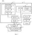
FIG. 2 is a functional block diagram of the head-mounted display device in an embodiment of the present invention; -
FIG. 3 is a flowchart of a control method of the head-mounted display device in accordance with an embodiment of the present invention. - The technical solution in the embodiments of the present invention will be described clearly and completely hereinafter with reference to the accompanying drawings in the embodiments of the present invention. Obviously, the described embodiments are merely some but not all embodiments of the present invention. All other embodiments obtained by a person of ordinary skilled in the art based on the embodiments of the present invention without creative efforts shall fall within the protection scope of the present invention.
- Referring to
FIGS. 1 and2 together,FIG. 1 is a stereo schematic view of a head-mounteddisplay device 100 in accordance with an embodiment of the present invention. The head-mounteddisplay device 100 includes a head-mountedapparatus 10, afunctional apparatus 20, adata line 30, atouch pad 40 located on thedata line 30, and aprocessor 50. The head-mountedapparatus 10 and thefunctional apparatus 20 perform signal transmission through thedata line 30. Therein, thefunctional apparatus 20 is a control device having a shape of box. - The
touch pad 40 is located on thedata line 30, configured to generate a touch signal in response to a touch operation. Theprocessor 50 is configured to receive the touch signal and generate a corresponding control signal according to the touch signal so as to control to execute a corresponding function. - In one embodiment, the head-mounted
display device 100 further includes atouch interface unit 60. Thetouch pad 40 is coupled to theprocessor 50 through thetouch interface unit 60, and transmits the touch signal to theprocessor 50 through thetouch interface unit 60. - In one embodiment, the
processor 50 and thetouch interface unit 60 are located on thefunctional apparatus 20, and are electrically coupled to each other. Theprocessor 50 outputs the corresponding control signal through the data line 31, or outputs the corresponding data to the head-mountedapparatus 10 according to the control signal, so as to control the head-mountedapparatus 10 to execute the corresponding function. - The head-mounted
apparatus 10 includes adisplay apparatus 11 and anearphone apparatus 12 coupled to each other. Thedisplay apparatus 11 is configured to provide display images. Theearphone apparatus 12 is configured to provide sound. - In another embodiment, the
processor 50 and thetouch interface unit 60 are located on theearphone apparatus 12 or thedisplay apparatus 11 of the head-mountedapparatus 10, and theprocessor 50 is electrically coupled to thetouch interface unit 60. - Therein, the
touch pad 40 is a flexible touch pad, and wraps around a periphery of thedata line 30. When thetouch interface unit 60 is located on thefunctional apparatus 20, one end of thetouch pad 40 extends to a location close to thefunctional apparatus 20, and further coupled to thetouch interface unit 60 through a plug connection way or other ways. Therefore, thetouch panel 40 establishes a data connection with theprocessor 60 through thetouch interface unit 40. - In comparison with a current way of placing the
touch pad 40 on thefunctional apparatus 20 or theearphone apparatus 12, a volume and a weight of thefunctional apparatus 20 or theearphone apparatus 12 can be decreased. Moreover, in thedata line 30 of the present invention, a touch signal transmission wire for transmitting the touch signal from theearphone apparatus 12 to thefunctional apparatus 20 may also be omitted, and a size of thedata line 30 is also reduced. - Referring to
FIG. 2 together,FIG. 2 is a functional block diagram of the head-mounteddisplay device 100. In one embodiment, the head-mountedapparatus 10 further includes afirst data interface 12 and an audio andvideo processor 14. Thefunctional apparatus 20 includes asecond data interface 21, apower unit 22 and astorage unit 23. Thestorage unit 23 stores a number of audio and video files. Therein, thefirst data interface 13 and the audio andvideo processor 14 can be located on any one of thedisplay apparatus 11 and theearphone apparatus 12.FIG. 1 shows an example that thefirst data interface 13 is located on theearphone apparatus 12. - The
first data interface 122 of the head-mountedapparatus 10 is coupled to thesecond data interface 21 of thefunctional apparatus 20 through thedata line 30, a connection between the head-mountedapparatus 10 and thefunctional apparatus 20 is accordingly established. Thepower unit 22 of thefunctional apparatus 20 provides aworking voltage to the head-mountedapparatus 10 through thedata line 30. Thedata line 30 is configured to supply power and transmit data, including a power supply wire core for supplying power, and a control signal wire core for transmitting the control signal, and the like. - In this embodiment, the
processor 50 is electrically coupled to thetouch pad 40 through thetouch interface unit 60. Theprocessor 50 is configured to receive the touch signal generated by thetouch pad 40, and determine the corresponding function according to the touch signal, and further generate the control signal for controlling to execute the corresponding function. - In this embodiment, when the
processor 50 receives the touch signal, theprocessor 50 estimates an output state of the head-mountedapparatus 10, and determines the corresponding function according to the touch signal and the current output state. In detail, when theprocessor 50 receives the touch signal, theprocessor 50 estimates whether the current output state is an audio and video playing state or not. When theprocessor 50 determines that the current output state is not the audio and video playing state, and the touch operation is a sliding operation, theprocessor 50 generates a control signal for menu option switching. When theprocessor 50 determines that the current output state is the audio and video playing state, and the touch operation is a click, theprocessor 50 generates a control signal of playing the current audio and video file or pause the current audio and video file, or the touch operation is a double-click, theprocessor 50 generates a control signal of awakening a menu, or the touch operation is the sliding operation, theprocessor 50 generates a control signal of adjusting the playing volume, or the like. - In this embodiment, the click and the double-click are both touch operations which are performed by at least two fingers simultaneously. The
processor 50 determines that there are at least two fingers sliding when it is determined that there are at least two touch points according to the touch signal. Theprocessor 50 determines that it is the click when a touching time duration is less than a first time duration, such as 0.2 seconds, according to the received touch signal, and determines that it is the double-click when there are two clicks at a predefined time duration, such as 1 seconds, according to the received touch signal. When theprocessor 50 determines that the touching time duration of at least two touch points is greater than a second time duration, such as 1 seconds, according to the received touch signal, theprocessor 50 determines whether the coordinates of the touch points are changed. If the coordinates of the touch points are changed, theprocessor 50 determines that it is the sliding operation, and further adjusts the volume according to a changing direction of the coordinates of the touch points. For example, when it is determined that the changing direction of the coordinates of the touch points is a first direction, the volume is controlled to increase, when it is determined that the changing direction of the coordinates of the touch points is a second direction, the volume is controlled to decrease. - In one embodiment, the
processor 50 determines whether the touch operation is a locking or unlocking touch operation according to the touch signal, and further generates a corresponding locking or unlocking control signal. In detail, in this embodiment, the locking or unlocking touch operation is a long press operation. When theprocessor 50 determines that the touching time duration is continuously greater than the second time duration and the coordinates of the touch points are not changed, it is determined to be the long press operation. Theprocessor 50 controls thetouch pad 40 to switch to be a locking state or an unlocking state according to the current state of thetouch pad 40. That is, a control signal for controlling thetouch pad 40 to switch to be the locking state or the unlocking state is generated to thetouch pad 40, and thetouch pad 40 is controlled to lock or unlock according to the control signal. For example, when the touch operation is the long press touch operation and the current state of the touch pad is in the unlocking state, thetouch pad 40 is thus controlled to be locked. When the touch pad is in the locking state, thetouch pad 40 is thus controlled to be unlocked. - When the
touch pad 40 is locked, theprocessor 50 receives the touch signal generated by thetouch pad 40 but does not respond. Unless the touch signal is corresponding to a lock/unlock operation. Therefore, when thetouch pad 40 is not needed to use, thetouch pad 40 can be locked, thereby avoiding wrong operations. Obviously, when thetouch pad 40 is unlocked, theprocessor 50 receives the touch signal generated by thetouch pad 40 and further processes it accordingly. - In one embodiment, when the
processor 50 determines that the touch operation is the sliding operation, and the current state of the head-mountedapparatus 10 is the audio and video playing state, theprocessor 50 further determines the corresponding function according to the sliding direction, and generates the control signal for executing the corresponding function. Therein, when theprocessor 50 determines that the sliding direction is a direction of sliding up and down, a control signal for adjusting the volume is adjusted. When theprocessor 50 determines that the sliding direction is a direction of sliding left and right, the corresponding function is determined to be fast forward or fast backward, a control signal for controlling the audio and video file currently to play fast forward or fast backward is generated. Therein, the direction of sliding up and down is sliding on thetouch pad 40 and sliding along a lengthwise direction of thedata line 30 located on thetouch pad 40. The direction of sliding left and right is sliding on thetouch pad 40 and sliding along a direction perpendicular to thedata line 30. For example, the data line is pinched by two fingers of the user and then twisted. - Obviously, the touch operations are but not limited to above touch operations. The functions are but not limited to above functions. The relationship between the touch operations and the functions are but not limited to above relationship. For example, the touch operation can also be a circle operation, when the current interface is an interface of playing audio and video, the corresponding function is loop playback. In other embodiment, the double click is corresponding to the function of locking/unlocking, the long press operation is corresponding to the function of awakening menu.
- In some embodiments, the
processor 50 determines that the function corresponding to the touch operation is to open a certain audio and video file, and controls to open a corresponding audio and video file stored in thestorage unit 23 and generate a multimedia signal mixing audio and video, and transmits the multimedia signal to the audio andvideo processor 14 of the head-mountedapparatus 10 through thedata line 30. The audio andvideo processor 14 receives the multimedia signal and decodes the multimedia signal into the video signal and the display signal, and transmits toheadphone apparatus 10 for the audio outputting, and transmits to thedisplay apparatus 11 for the display outputting respectively. Therein, theprocessor 50 can be a central processing unit, a micro controller, a single chip microcomputer, a digital signal processor, or the like. The audio andvideo processor 14 can be a decoding chip for decoding audio and video. Thestorage unit 23 can be a flash memory card, a disk, a solid state disk or the like. - As shown in
FIG. 2 , theheadphone apparatus 12 further includes anaudio drive unit 121 and atelephone receiver 122. Thedisplay apparatus 11 includes adisplay drive unit 111, adisplay 112 and anoptical module 113. Theprocessor 50 decodes the obtained multimedia signal into the audio signal and the display signal, and transmits the audio signal to theaudio drive unit 121, and transmits the display signal to thedisplay drive unit 111 of thedisplay apparatus 11 coupled to theheadphone apparatus 12. - The
audio drive unit 121 is configured to drive thetelephone receiver 122 to output the corresponding audio according to the audio signal. In detail, theaudio drive unit 121 is configured to convert the audio signal in form of the digital signal into the analog signal, and further drive thetelephone receiver 122 through the analog signal to output the corresponding volume. - The
display drive unit 111 is configured to drive thedisplay 12 to output the corresponding image according to the display signal. Theoptical module 113 is configured to project the display image displayed by thedisplay 12 into the user's eyes according to a predefined path. Therein, the display image includes the above interface of playing audio and video, and the interface of menu, and the like. - Therein, the
display 12 is a micro display. - Therein, as shown in
FIG.1 , theheadphone apparatus 12 further includes anannular belt 123. The number of thetelephone receiver 122 is two. The twotelephone receivers 122 are located on two ends of theannular belt 123. The twotelephone receivers 122 are electrically coupled to each other through theannular belt 123. - In one embodiment, the
processor 50 transmits the obtained multimedia signal to the audio andvideo processor 14. The audio andvideo processor 14 decodes the multimedia signal into the video signal and the display signal, controls to transmit the display signal to thedisplay apparatus 11 for the display outputting, and then transmits the audio signal to theheadphone apparatus 10 for the audio outputting. - As shown in
FIG. 3, FIG. 3 is a flowchart of a method of the head-mounted display device in accordance with an embodiment of the present invention. The method is configured to control the head-mounted display device described above in any one embodiment. The method includes the steps as follows. - The
processor 50 receives the touch signal generated by thetouch pad 40 located on thedata line 30 coupling thefunctional apparatus 20 to the head-mounted apparatus 10 (S401). - The
processor 50 determines the corresponding function according to the touch signal and the current output state of the head-mounted apparatus 10 (S403). Therein, when the current output state of the head-mountedapparatus 10 is not the audio and video playing state, and the touch operation is the sliding operation, theprocessor 50 determines that the corresponding function is a function of menu option switching. When the current output state of the head-mountedapparatus 10 is the audio and video playing state, and the touch operation is the sliding operation, theprocessor 50 determines that the corresponding function is a function of adjusting volume. When the current output state of the head-mountedapparatus 10 is the audio and video playing state, and the touch operation is the click, theprocessor 50 determines that the corresponding function is pause. When the current output state of the head-mountedapparatus 10 is the audio and video playing state, and the touch operation is the double-click, theprocessor 50 determines that the corresponding function is a function of awakening the menu, such as, awakening the menu of audio and video files list of the playing interface. - The
processor 50 generates the control signal for controlling to execute the corresponding function, and controls to execute the corresponding function(S405). - Therein, in one embodiment, the method further includes steps: when the
processor 50 determines that the touch operation is a locking or unlocking touch operation according to the touch signal, and controls thetouch pad 40 to switch to be the locking state or the unlocking state. In detail, in this embodiment, the locking or unlocking touch operation is the long press touch operation, when theprocessor 50 determines that the touching time duration is continuously greater than the second time duration and the coordinates of the touch points are not changed, it is determined to be the long press operation, and thetouch pad 40 is controlled to be switched into the locking state or the unlocking state. - Therein, in one embodiment, the method further includes steps: the
processor 50 determines that the function corresponding to the touch operation is opening a certain audio and video file, controls to open a corresponding audio and video file stored in thestorage unit 23 and generates a multimedia signal mixing the audio and the video, and transmits the multimedia signal to the audio andvideo processor 14 of the head-mountedapparatus 10 through thedata line 30. The audio andvideo processor 14 receives the multimedia signal and decodes the multimedia signal into the video signal and the display signal, and transmits to theheadphone apparatus 10 for the audio outputting, and transmits to thedisplay apparatus 11 for the display outputting. - The above is a preferred embodiment of the present invention, and it should be noted that those skilled in the art may make some improvements and modifications without departing from the principle of the present invention, and these improvements and modifications are also the protection scope of the present invention.
Claims (19)
- A head-mounted display device, wherein, the head-mounted display device comprises a head-mounted apparatus, and a functional apparatus, and a data line coupled the head-mounted apparatus and the functional apparatus, the head-mounted apparatus comprises a display apparatus for providing a near-bye display, the functional apparatus and the head-mounted apparatus perform signal transmission through the data line, the head-mounted display device further comprises:a touch pad, located on the data line, configured to generate a touch signal in response to a touch operation;a processor, configured to generate a corresponding control signal according to the touch signal.
- The head-mounted display device according to claim 1, wherein the processor is located on the functional apparatus, the processor outputs the control signal to the head-mounted apparatus to the head-mounted apparatus to control the head-mounted apparatus to execute a corresponding function.
- The head-mounted display device according to claim 2, wherein the functional apparatus further comprises a touch interface unit coupling the processor and the touch pad, the touch interface unit receives the touch signal generated by the touch pad and transmits the touch signal to the processor.
- The head-mounted display device according to claim 1, wherein the processor is located on the display apparatus, the display apparatus further comprises a touch interface unit coupling the processor and the touch pad, configured to receive the touch signal generated by the touch pad and transmits the touch signal to the processor.
- The head-mounted display device according to claims 1, wherein the head-mounted apparatus further comprises a headphone apparatus, configured for outputting audio.
- The head-mounted display device according to claim 5, wherein the processor is located on the headphone apparatus, the headphone apparatus further comprises a touch interface unit coupling the processor to the touch pad, the touch interface unit is configured to receive the touch signal generated by the touch pad and transmits the touch signal to the processor.
- The head-mounted display device according to claim 5, wherein the head-mounted apparatus further comprises an audio and video processor, configured to process an audio and video signal into a display signal for the display apparatus outputting and an audio signal for the headphone apparatus outputting.
- The head-mounted display device according to claim 7, wherein the processor determines that the control signal is to open a certain audio and video file according to the touch signal, the processor controls to open a corresponding audio and video file stored in a storage unit and generates a multimedia signal mixing audio and video, and further transmits the multimedia signal to the audio and video processor through the data line, the audio and video processor receives the multimedia signal and decodes the multimedia signal into the audio signal and the display signal, and transmits to the headphone apparatus for the audio outputting, and transmits to the display apparatus for the display outputting.
- The head-mounted display device according to claim 1, wherein the touch pad is a flexible touch pad, wrapping around a periphery of the data line.
- The head-mounted display device according to claim 1, wherein, the processor determines the corresponding control signal according to the touch signal of the touch pad and an output state of the head-mounted apparatus.
- The head-mounted display device according to claim 10, wherein, when the processor receives the touch signal, the processor estimates whether a current output state of the head-mounted apparatus is an audio and video playing state or not; when the current output state is not the audio and video playing state, the processor generates a control signal for menu option switching according to the touch signal corresponding to a sliding operation; when the current output state is the audio and video playing state, the processor generates a control signal of playing the current audio and video file or pause the current audio and video file according to the touch signal corresponding to a click, or generates a control signal of awakening a menu according to the touch signal corresponding to a double-click, or generates a control signal of adjusting playing volume according to the control signal corresponding to a sliding operation.
- The head-mounted display device according to claim 7, wherein, the processor further generates the control signal for controlling the corresponding function according to a sliding direction according to the touch signal corresponding to the sliding operation, and the current output state of the head-mounted apparatus is the audio and video playing state; when the processor determines that it is a direction of sliding up and down, a control signal for adjusting volume is generated to adjust volume; when it is determined that the sliding direction is a direction of sliding left and right, a control signal for controlling to fast forward or fast backward is generated, for controlling the audio and video file currently playing to fast forward or fast backward.
- The head-mounted display device according to claim 7, wherein, the processor determines that it is the click when there are at least two touch points and a touching time duration of the at least two touch points is less than a first time duration; the processor determines that it is the double-click when there are two clicks at a predefined time duration; the processor determines whether coordinates of the touch points are changed; if the coordinates of the touch points are changed, it is determined to be the sliding operation.
- The head-mounted display device according to claim 2, wherein, the processor controls the touch pad to switch to be a locking state or an unlocking state when the control signal is a control signal for unlocking/locking.
- The head-mounted display device according to claim 8, wherein,the headphone apparatus further comprises an audio drive unit and telephone receivers; the display apparatus comprises a display drive unit, a display and an optical module, the audio and video processorreceives the multimedia signal transmitted by the processor, decodes the multimedia signal into the audio signal and the display signal, and transmits the audio signal to the audio drive unit, and transmits the display signal to the display drive unit of the display apparatus coupled to the headphone apparatus, the audio drive unit drives the telephone receivers to output the corresponding volume according to the audio signal, and the display drive unit drives the display to output corresponding images according to the display signal, the optical module is configured to project the display image displayed by the display into user's eyes according to a predefined path.
- A control method of a head-mounted display device, wherein, the head-mounted display device comprises a head-mounted apparatus, a functional apparatus, a data line coupled the head-mounted apparatus to the functional apparatus, and a touch pad located on the data line, the method comprises:generating a touch signal in response to a touch operation by the touch pad;determining a corresponding function according to the touch signal and an output state of the head-mounted apparatus by the head-mounted display device;outputting a control signal of controlling the corresponding function to control to execute the corresponding function.
- The control method according to claim 16, wherein, the step "the head-mounted display device determines a corresponding function according to the touch signal and an output state of the head-mounted apparatus" comprises:when a current output state is not an audio and video playing state, and the touch operation is a sliding operation, a control signal for menu option switching is outputted;when the current output state is the audio and video playing state and the touch operation is the sliding operation, a control signal for menu option switching is outputted;when the current output state is the audio and video playing state and the touch operation is a click, a control signal of pause is outputted;when the current output state is the audio and video playing state and the touch operation is a double-click, a control signal of awakening a menu is outputted.
- The control method according to claim 16, wherein, the method further comprises:
controlling the touch pad to switch to be a locking state or an unlocking state when the processor determines that the control signal is a control signal for unlocking/locking, to enable the touch pad to be touched or not touched. - The control method according to claim 16, wherein, the method further comprises:when it is determined that the corresponding function is to open a certain audio and video file according to the touch signal, opening a corresponding audio and video file and generates a multimedia signal mixing audio and video;transmitting the multimedia signal to the head-mounted apparatus through the data line;decoding the multimedia signal into the audio signal and the display signal, transmitting to the headphone apparatus for the audio outputting, and transmitting to the display apparatus for the display outputting respectively.
Applications Claiming Priority (1)
| Application Number | Priority Date | Filing Date | Title |
|---|---|---|---|
| PCT/CN2015/099868 WO2017113188A1 (en) | 2015-12-30 | 2015-12-30 | Head-mounted display device and control method therefor |
Publications (2)
| Publication Number | Publication Date |
|---|---|
| EP3399361A1 true EP3399361A1 (en) | 2018-11-07 |
| EP3399361A4 EP3399361A4 (en) | 2019-07-10 |
Family
ID=59224283
Family Applications (1)
| Application Number | Title | Priority Date | Filing Date |
|---|---|---|---|
| EP15911817.3A Withdrawn EP3399361A4 (en) | 2015-12-30 | 2015-12-30 | Head-mounted display device and control method therefor |
Country Status (6)
| Country | Link |
|---|---|
| US (1) | US10545345B2 (en) |
| EP (1) | EP3399361A4 (en) |
| JP (1) | JP2019506776A (en) |
| KR (1) | KR20180084901A (en) |
| CN (1) | CN107407805A (en) |
| WO (1) | WO2017113188A1 (en) |
Families Citing this family (3)
| Publication number | Priority date | Publication date | Assignee | Title |
|---|---|---|---|---|
| KR20200002610A (en) * | 2018-06-29 | 2020-01-08 | 캐논 가부시끼가이샤 | Electronic device, control method for electronic device, and computer readable medium |
| CN111654777B (en) * | 2020-06-29 | 2025-08-19 | 歌尔科技有限公司 | Head-mounted display device and head-mounted display assembly |
| CN114935969A (en) * | 2022-07-21 | 2022-08-23 | 杭州灵伴科技有限公司 | Head-mounted display suite and power-off method based on physical connection |
Family Cites Families (36)
| Publication number | Priority date | Publication date | Assignee | Title |
|---|---|---|---|---|
| US20040001106A1 (en) * | 2002-06-26 | 2004-01-01 | John Deutscher | System and process for creating an interactive presentation employing multi-media components |
| US20050003851A1 (en) * | 2003-06-05 | 2005-01-06 | Visteon Global Technologies, Inc. | Radio system with touch pad interface |
| JP2006189476A (en) | 2004-12-28 | 2006-07-20 | Konica Minolta Photo Imaging Inc | Display system |
| CN1304931C (en) * | 2005-01-27 | 2007-03-14 | 北京理工大学 | Head carried stereo vision hand gesture identifying device |
| US8769408B2 (en) * | 2005-10-07 | 2014-07-01 | Apple Inc. | Intelligent media navigation |
| US8094673B2 (en) * | 2006-04-10 | 2012-01-10 | Microsoft Corporation | Cable user interface |
| US8605008B1 (en) * | 2007-05-04 | 2013-12-10 | Apple Inc. | Head-mounted display |
| CN201278050Y (en) | 2008-09-04 | 2009-07-22 | 深圳市力伟数码技术有限公司 | Computer tri-dimensional glass display having VGA interface |
| KR101521219B1 (en) * | 2008-11-10 | 2015-05-18 | 엘지전자 주식회사 | Mobile terminal using flexible display and operation method thereof |
| WO2011084895A1 (en) * | 2010-01-08 | 2011-07-14 | Kopin Corporation | Video eyewear for smart phone games |
| US9047005B2 (en) * | 2011-02-03 | 2015-06-02 | Sony Corporation | Substituting touch gestures for GUI or hardware keys to control audio video play |
| JP5810540B2 (en) | 2011-02-04 | 2015-11-11 | セイコーエプソン株式会社 | Head-mounted display device and method for controlling head-mounted display device |
| KR101831644B1 (en) | 2011-03-02 | 2018-02-23 | 삼성전자 주식회사 | Earphone having the touch input unit and a portable terminal using the same |
| US9042571B2 (en) * | 2011-07-19 | 2015-05-26 | Dolby Laboratories Licensing Corporation | Method and system for touch gesture detection in response to microphone output |
| US8217856B1 (en) * | 2011-07-27 | 2012-07-10 | Google Inc. | Head-mounted display that displays a visual representation of physical interaction with an input interface located outside of the field of view |
| JP5978592B2 (en) * | 2011-10-26 | 2016-08-24 | ソニー株式会社 | Head mounted display and display control method |
| JP5957875B2 (en) * | 2011-12-26 | 2016-07-27 | ソニー株式会社 | Head mounted display |
| US20130207715A1 (en) * | 2012-02-13 | 2013-08-15 | Nokia Corporation | Method, Apparatus, Computer Program, Cable and System |
| US9143858B2 (en) * | 2012-03-29 | 2015-09-22 | Csr Technology Inc. | User designed active noise cancellation (ANC) controller for headphones |
| KR20140052294A (en) * | 2012-10-24 | 2014-05-07 | 삼성전자주식회사 | Method for providing user with virtual image in head-mounted display device, machine-readable storage medium and head-mounted display device |
| JP5600360B2 (en) * | 2013-01-25 | 2014-10-01 | ソフトバンクモバイル株式会社 | Program and moving image playback control device |
| JP6209906B2 (en) * | 2013-09-05 | 2017-10-11 | セイコーエプソン株式会社 | Head-mounted display device, method for controlling head-mounted display device, and image display system |
| JP6144167B2 (en) * | 2013-09-27 | 2017-06-07 | 株式会社河合楽器製作所 | Metronome program |
| JP2015087581A (en) | 2013-10-31 | 2015-05-07 | 株式会社東芝 | Display device |
| CN103576578B (en) | 2013-11-05 | 2017-04-12 | 小米科技有限责任公司 | Method, device and equipment for adopting earphone wire to control terminal |
| JP6264014B2 (en) | 2013-12-17 | 2018-01-24 | セイコーエプソン株式会社 | Head-mounted display device |
| JP2015143812A (en) | 2013-12-24 | 2015-08-06 | セイコーエプソン株式会社 | Electro-optical device and electronic apparatus |
| JP2017511041A (en) * | 2014-02-18 | 2017-04-13 | マージ ラブス インコーポレイテッド | Head mounted display goggles for use with mobile computing devices |
| US9649558B2 (en) * | 2014-03-14 | 2017-05-16 | Sony Interactive Entertainment Inc. | Gaming device with rotatably placed cameras |
| CN103901791A (en) | 2014-04-02 | 2014-07-02 | 联想(北京)有限公司 | Response key touch operating method and device and electronic device |
| WO2015176037A1 (en) * | 2014-05-16 | 2015-11-19 | T-Ink, Inc. | Devices and techniques relating to a touch sensitive control device |
| US9734315B2 (en) * | 2014-09-01 | 2017-08-15 | Lg Electronics Inc. | Wearable terminal |
| US9794684B2 (en) * | 2015-02-13 | 2017-10-17 | Seiko Epson Corporation | Head-mounted display device, control method for the same, and computer program |
| US10156721B2 (en) * | 2015-03-09 | 2018-12-18 | Microsoft Technology Licensing, Llc | User-based context sensitive hologram reaction |
| US20160378204A1 (en) * | 2015-06-24 | 2016-12-29 | Google Inc. | System for tracking a handheld device in an augmented and/or virtual reality environment |
| CN204719350U (en) | 2015-06-29 | 2015-10-21 | 西北农林科技大学 | A kind of Wearable amusement type glasses |
-
2015
- 2015-12-30 KR KR1020187016764A patent/KR20180084901A/en not_active Ceased
- 2015-12-30 CN CN201580076868.2A patent/CN107407805A/en not_active Withdrawn
- 2015-12-30 EP EP15911817.3A patent/EP3399361A4/en not_active Withdrawn
- 2015-12-30 JP JP2018530881A patent/JP2019506776A/en active Pending
- 2015-12-30 WO PCT/CN2015/099868 patent/WO2017113188A1/en not_active Ceased
- 2015-12-30 US US15/751,427 patent/US10545345B2/en not_active Expired - Fee Related
Also Published As
| Publication number | Publication date |
|---|---|
| JP2019506776A (en) | 2019-03-07 |
| US10545345B2 (en) | 2020-01-28 |
| US20180239142A1 (en) | 2018-08-23 |
| WO2017113188A1 (en) | 2017-07-06 |
| KR20180084901A (en) | 2018-07-25 |
| CN107407805A (en) | 2017-11-28 |
| EP3399361A4 (en) | 2019-07-10 |
Similar Documents
| Publication | Publication Date | Title |
|---|---|---|
| EP2587300B1 (en) | Head mount display and display control method | |
| CN104007813A (en) | Display control apparatus, display apparatus, display control method, and program | |
| US20160073200A1 (en) | Headset | |
| EP2557561A2 (en) | Mobile information display terminal | |
| US10841468B2 (en) | Display apparatus for displaying operating section for receiving operation, image pickup apparatus, image pickup system, control method of display apparatus, and storage medium | |
| EP3373032B1 (en) | Method and device for determining status of terminal, and terminal | |
| US10306397B2 (en) | Method for automatically connecting a short-range communication between two devices and apparatus for the same | |
| KR101310941B1 (en) | Display apparatus for displaying a plurality of content views, shutter glasses device for syncronizing with one of the content views and methods thereof | |
| US20140085183A1 (en) | Head-mounted display apparatus and control method thereof | |
| CN102300128B (en) | Information processing apparatus and method for controlling same | |
| EP3103020B1 (en) | User terminal and control method thereof | |
| CN107852435A (en) | Mobile terminal and its control method | |
| KR20160029551A (en) | Electronic device, and method for operating the same | |
| US20140217962A1 (en) | Charging apparatus and charging method | |
| US10545345B2 (en) | Head-mounted display device with function of touch input and touch control method thereof | |
| EP3399364A1 (en) | Head-mounted display device and head-mounted display system | |
| KR20160023212A (en) | Glass type mobile terminal and method for controlling the same | |
| KR20170027607A (en) | Wearable device and method for controlling the same | |
| US20100214479A1 (en) | Broadcasting receiving apparatus | |
| CN111988693A (en) | Earphone control method and system based on earphone charging box and readable storage medium | |
| CN103902395B (en) | The control method and electric terminal of information input | |
| KR20150084388A (en) | Sound accessory for automatic control | |
| CN204810462U (en) | Two mesh display system | |
| KR20150119640A (en) | Mobile terminal and method for controlling the same | |
| KR101733003B1 (en) | Mobile terminal and method for controlling the same |
Legal Events
| Date | Code | Title | Description |
|---|---|---|---|
| STAA | Information on the status of an ep patent application or granted ep patent |
Free format text: STATUS: THE INTERNATIONAL PUBLICATION HAS BEEN MADE |
|
| PUAI | Public reference made under article 153(3) epc to a published international application that has entered the european phase |
Free format text: ORIGINAL CODE: 0009012 |
|
| STAA | Information on the status of an ep patent application or granted ep patent |
Free format text: STATUS: REQUEST FOR EXAMINATION WAS MADE |
|
| 17P | Request for examination filed |
Effective date: 20180409 |
|
| AK | Designated contracting states |
Kind code of ref document: A1 Designated state(s): AL AT BE BG CH CY CZ DE DK EE ES FI FR GB GR HR HU IE IS IT LI LT LU LV MC MK MT NL NO PL PT RO RS SE SI SK SM TR |
|
| AX | Request for extension of the european patent |
Extension state: BA ME |
|
| DAV | Request for validation of the european patent (deleted) | ||
| DAX | Request for extension of the european patent (deleted) | ||
| A4 | Supplementary search report drawn up and despatched |
Effective date: 20190612 |
|
| RIC1 | Information provided on ipc code assigned before grant |
Ipc: G06F 3/0354 20130101ALI20190605BHEP Ipc: G06F 1/16 20060101ALI20190605BHEP Ipc: G06F 3/0488 20130101ALI20190605BHEP Ipc: G06F 3/01 20060101ALI20190605BHEP Ipc: G02B 27/01 20060101AFI20190605BHEP |
|
| STAA | Information on the status of an ep patent application or granted ep patent |
Free format text: STATUS: THE APPLICATION HAS BEEN WITHDRAWN |
|
| 18W | Application withdrawn |
Effective date: 20190923 |