EP3399293A1 - Measuring block for fibre web machine - Google Patents
Measuring block for fibre web machine Download PDFInfo
- Publication number
- EP3399293A1 EP3399293A1 EP18168169.3A EP18168169A EP3399293A1 EP 3399293 A1 EP3399293 A1 EP 3399293A1 EP 18168169 A EP18168169 A EP 18168169A EP 3399293 A1 EP3399293 A1 EP 3399293A1
- Authority
- EP
- European Patent Office
- Prior art keywords
- measuring block
- sensor devices
- fabric
- fastening piece
- piece
- Prior art date
- Legal status (The legal status is an assumption and is not a legal conclusion. Google has not performed a legal analysis and makes no representation as to the accuracy of the status listed.)
- Granted
Links
Images

Classifications
-
- B—PERFORMING OPERATIONS; TRANSPORTING
- B65—CONVEYING; PACKING; STORING; HANDLING THIN OR FILAMENTARY MATERIAL
- B65H—HANDLING THIN OR FILAMENTARY MATERIAL, e.g. SHEETS, WEBS, CABLES
- B65H23/00—Registering, tensioning, smoothing or guiding webs
- B65H23/04—Registering, tensioning, smoothing or guiding webs longitudinally
- B65H23/044—Sensing web tension
-
- G—PHYSICS
- G01—MEASURING; TESTING
- G01L—MEASURING FORCE, STRESS, TORQUE, WORK, MECHANICAL POWER, MECHANICAL EFFICIENCY, OR FLUID PRESSURE
- G01L5/00—Apparatus for, or methods of, measuring force, work, mechanical power, or torque, specially adapted for specific purposes
- G01L5/04—Apparatus for, or methods of, measuring force, work, mechanical power, or torque, specially adapted for specific purposes for measuring tension in flexible members, e.g. ropes, cables, wires, threads, belts or bands
-
- D—TEXTILES; PAPER
- D21—PAPER-MAKING; PRODUCTION OF CELLULOSE
- D21F—PAPER-MAKING MACHINES; METHODS OF PRODUCING PAPER THEREON
- D21F7/00—Other details of machines for making continuous webs of paper
-
- D—TEXTILES; PAPER
- D21—PAPER-MAKING; PRODUCTION OF CELLULOSE
- D21F—PAPER-MAKING MACHINES; METHODS OF PRODUCING PAPER THEREON
- D21F7/00—Other details of machines for making continuous webs of paper
- D21F7/005—Wire-tensioning devices
-
- D—TEXTILES; PAPER
- D21—PAPER-MAKING; PRODUCTION OF CELLULOSE
- D21G—CALENDERS; ACCESSORIES FOR PAPER-MAKING MACHINES
- D21G9/00—Other accessories for paper-making machines
-
- G—PHYSICS
- G01—MEASURING; TESTING
- G01L—MEASURING FORCE, STRESS, TORQUE, WORK, MECHANICAL POWER, MECHANICAL EFFICIENCY, OR FLUID PRESSURE
- G01L5/00—Apparatus for, or methods of, measuring force, work, mechanical power, or torque, specially adapted for specific purposes
- G01L5/0004—Force transducers adapted for mounting in a bore of the force receiving structure
-
- G—PHYSICS
- G01—MEASURING; TESTING
- G01L—MEASURING FORCE, STRESS, TORQUE, WORK, MECHANICAL POWER, MECHANICAL EFFICIENCY, OR FLUID PRESSURE
- G01L5/00—Apparatus for, or methods of, measuring force, work, mechanical power, or torque, specially adapted for specific purposes
- G01L5/04—Apparatus for, or methods of, measuring force, work, mechanical power, or torque, specially adapted for specific purposes for measuring tension in flexible members, e.g. ropes, cables, wires, threads, belts or bands
- G01L5/10—Apparatus for, or methods of, measuring force, work, mechanical power, or torque, specially adapted for specific purposes for measuring tension in flexible members, e.g. ropes, cables, wires, threads, belts or bands using electrical means
- G01L5/102—Apparatus for, or methods of, measuring force, work, mechanical power, or torque, specially adapted for specific purposes for measuring tension in flexible members, e.g. ropes, cables, wires, threads, belts or bands using electrical means using sensors located at a non-interrupted part of the flexible member
-
- G—PHYSICS
- G01—MEASURING; TESTING
- G01L—MEASURING FORCE, STRESS, TORQUE, WORK, MECHANICAL POWER, MECHANICAL EFFICIENCY, OR FLUID PRESSURE
- G01L5/00—Apparatus for, or methods of, measuring force, work, mechanical power, or torque, specially adapted for specific purposes
- G01L5/04—Apparatus for, or methods of, measuring force, work, mechanical power, or torque, specially adapted for specific purposes for measuring tension in flexible members, e.g. ropes, cables, wires, threads, belts or bands
- G01L5/10—Apparatus for, or methods of, measuring force, work, mechanical power, or torque, specially adapted for specific purposes for measuring tension in flexible members, e.g. ropes, cables, wires, threads, belts or bands using electrical means
- G01L5/108—Apparatus for, or methods of, measuring force, work, mechanical power, or torque, specially adapted for specific purposes for measuring tension in flexible members, e.g. ropes, cables, wires, threads, belts or bands using electrical means for measuring a reaction force applied on a single support, e.g. a glider
-
- B—PERFORMING OPERATIONS; TRANSPORTING
- B65—CONVEYING; PACKING; STORING; HANDLING THIN OR FILAMENTARY MATERIAL
- B65H—HANDLING THIN OR FILAMENTARY MATERIAL, e.g. SHEETS, WEBS, CABLES
- B65H2553/00—Sensing or detecting means
- B65H2553/60—Details of intermediate means between the sensing means and the element to be sensed
- B65H2553/61—Mechanical means, e.g. contact arms
-
- B—PERFORMING OPERATIONS; TRANSPORTING
- B65—CONVEYING; PACKING; STORING; HANDLING THIN OR FILAMENTARY MATERIAL
- B65H—HANDLING THIN OR FILAMENTARY MATERIAL, e.g. SHEETS, WEBS, CABLES
- B65H2553/00—Sensing or detecting means
- B65H2553/80—Arangement of the sensing means
- B65H2553/81—Arangement of the sensing means on a movable element
Definitions
- Finnish utility model number 6399 presents an arrangement for the measurement of the tension of a fabric in a fibre web machine.
- the arrangement there is a pivoted measuring block between the frame of the fibre web machine and a roll that supports the fabric, with the measuring block containing sensor devices.
- the tension of the fabric accomplishes a movement of the measuring block with respect to the pivot point, and the tension of the fabric can be determined from this movement by means of the sensor devices.
- the measuring block is susceptible to wobble due to the pivoted structure.
- the sensor devices include only one sensor, in which case a failure of the sensor may go unnoticed.
- Another known measuring block uses two support points, each with a sensor.
- the functioning of the sensor devices can be ensured by comparing the readings of the sensors.
- a failure of the sensor devices can be detected, in which case it is possible to avoid any consequential implications.
- the sensors are, however, placed in separate measuring positions.
- each sensor measures a different process variable, or they measure the same process variable, but its different component due to the geometry differences of the support points. These differences impair the reliability of the detection of failure based on the measurement difference.
- the object of the present invention is to accomplish a novel kind of measuring block for a fibre web machine, which measuring block has a simpler structure than earlier but the measuring result of which measuring block is more reliable than earlier.
- the characteristic features of the measuring block according to the present invention are described in the enclosed claims.
- the sensor devices have been supported in a novel and surprising way. In this case, it is possible to use smaller sensor devices than earlier.
- the measuring block becomes stable, which reduces wobble in the control of the tension of the fabric.
- the overloading protection is built in, in which case the structure of the measuring block remains simple.
- the measuring block can be located freely in positions with different kinds of geometries without compromising the accuracy or overloading protection of the sensor devices. More generally speaking, the measuring block is a tension measuring device.
- FIG. 1 shows part of the dryer section of a fibre web machine.
- the dryer section consists of several cylinder groups, each of which contains consecutive drying cylinders 10 and turn rolls 11.
- a fabric cycle consisting of a fabric 12, here a drying fabric, is supported via the drying cylinders and turn rolls.
- the fabric cycle is also supported by break back rolls 13, one of which has been equipped here with a fabric stretcher 14. In this case, it is possible to keep the fabric at the desired tension.
- the fabric stretcher can be used for loosening the fabric so that it is possible to change the fabric.
- the second break back roll 13 is supported by the measuring block 15, and the tension of the fabric 12 can be ascertained from the measurement result of the measuring block 15.
- the measured tension can then be used for controlling the fabric stretcher.
- the measuring block can also be used in connection with fabrics other than a drying fabric.
- a measuring block of duplexed measurement is installed at both ends of a break back roll, but even with one measuring block according to the invention at one end of the break back roll, it is possible to obtain duplexed measurement results that correspond to the tension of the fabric.
- the invention relates to a measuring block for a fibre web machine.
- the measuring block 15 in different situations is presented in Figures 2a - 3b .
- the measuring block 15 includes a support piece 16 and a fastening piece 17, which have been fastened to each other in a pivoting manner by means of a joint 18.
- the support piece and the fastening piece can pivot with respect to each other. Due to the joint, the movement of the support piece and the fastening piece is sensitive but sturdy.
- the support piece and the fastening piece are thick metal plate pieces, which can endure stresses without bending. In practice, the fastening piece is fastened to the frame of the fibre web machine, and the bearing pedestal of the break back roll that supports the fabric is fastened to the support piece.
- the fabric stretches as it becomes older, in which case the break back roll is shifted by using the fabric stretcher, and the desired tension is hence achieved.
- the fabric warms up in a web break, which can increase tension quite rapidly. In this case, the fabric is loosened to avoid damage.
- the axle 21 here is a deflecting axle, which has been supported in a floating manner, here to the fastening piece 17.
- the axle of the bogie hence constitutes in itself overloading protection without extra structures and external structures.
- the arrows at the axle 21 in Figure 2a illustrate the transmission of the force from the upper lugs 23 to the axle 21.
- the narrower arrows illustrate the transmission of the halved force from the bogie 22 to the fastening piece 17.
- the force is transmitted to the fastening piece.
- the deflection of the axle 21 removes the clearance 25 that has been arranged between the axle 21 and the lower lug 24 of the fastening piece 17.
- the force that exceeds the permitted maximum force is transmitted from the axle directly to the fastening piece.
- the clearance 25 has been implemented simply by a boring in the lower lug 24, which boring is slightly larger than the axle 21 ( Figure 2b ).
- the clearance is symmetrical, whereby the restriction of the force works irrespective of the direction of the force.
- the measuring block may hence be subject to either pulling or compression.
- the sensor devices function irrespective of the direction of the force.
- the measuring block can be placed in a position where the fabric tension pulls the support piece and the fastening piece apart from each other.
- the measuring block can also be installed upside down or turned 90 degrees, whereby, depending on the position, it is possible to make the measuring range of the sensor devices correspond to the actual load.
- the bogie 22 includes two end points 26, and the sensor devices 19 have been adapted in one of them or both of them.
- the bogie is advantageously symmetrical, whereby a force of the same magnitude is directed at both end points.
- the magnitudes of the forces are on a ratio to the distances.
- the structure of the measuring block can be adapted to the measuring range of the sensor devices by the selection of the end point.
- the sensor devices 19 include a pin sensor 27, with which the end point 26 has been supported to the fastening piece 17.
- the pin sensor is also the part that fastens the bogie to the fastening piece, and it serves as a joint, which simplifies the structure of the measuring block.
- the fastening piece 17 contains a fastening support 28 for the pin sensor.
- the bogie 22 is between two fastening supports 28. The structure is low, and the movement of the support piece 16 is small.
- the support piece is fastened to the frame of the fibre web machine.
- a roll that supports the fabric is fastened in this case to the fastening piece.
- the support piece and the fastening piece have been supported to each other by means of a joint.
- the tension of the fabric can be determined from the change in the mutual position of the support piece and the fastening piece, by using the sensor devices.
- the measuring block is often placed in hot circumstances, in which case stresses may occur between the parts due to the temperature differences. The stresses can cause an error in the measuring devices.
- the upper lug 23 has been fastened to the support piece 16 by means of a pivot pin 29. This avoids the transmission of stresses from the fastening piece to the bogie structure and vice versa.
Landscapes
- Physics & Mathematics (AREA)
- General Physics & Mathematics (AREA)
- Chemical & Material Sciences (AREA)
- Analytical Chemistry (AREA)
- Force Measurement Appropriate To Specific Purposes (AREA)
Abstract
Description
- The invention relates to a measuring block for a fibre web machine, which measuring block includes a support piece and a fastening piece, which have been fastened to each other in a pivoting manner by means of a joint, as well as sensor devices, which have been adapted between the support piece and the fastening piece on the measuring block in order to determine the tension of a fabric supported by a roll.
- Finnish utility model number
6399 - Another known measuring block uses two support points, each with a sensor. In this case, the functioning of the sensor devices can be ensured by comparing the readings of the sensors. In other words, a failure of the sensor devices can be detected, in which case it is possible to avoid any consequential implications. The sensors are, however, placed in separate measuring positions. In this case, each sensor measures a different process variable, or they measure the same process variable, but its different component due to the geometry differences of the support points. These differences impair the reliability of the detection of failure based on the measurement difference. At the same time, it is necessary to make an indirect definition of the measured variable that corresponds to the actual tension, which reduces the accuracy of the measured variable.
- In both of the solutions presented, overloading protection has been implemented by means of separate travel stops, which complicates the structure of the measuring block. Moreover, it is necessary to use sensors, which can withstand high stresses. Both of these drawbacks hence increase the manufacturing and operating costs of measuring blocks and enlarge the size of the measuring block.
- The object of the present invention is to accomplish a novel kind of measuring block for a fibre web machine, which measuring block has a simpler structure than earlier but the measuring result of which measuring block is more reliable than earlier. The characteristic features of the measuring block according to the present invention are described in the enclosed claims. In the measuring block according to the present invention, the sensor devices have been supported in a novel and surprising way. In this case, it is possible to use smaller sensor devices than earlier. At the same time, the measuring block becomes stable, which reduces wobble in the control of the tension of the fabric. Furthermore, the overloading protection is built in, in which case the structure of the measuring block remains simple. Moreover, the measuring block can be located freely in positions with different kinds of geometries without compromising the accuracy or overloading protection of the sensor devices. More generally speaking, the measuring block is a tension measuring device.
- The invention is described below in detail by making reference to the enclosed drawings that illustrate an embodiment of the invention, in which:
- Figure 1
- shows a drawing in principle of two measuring blocks adapted in the fabric cycles of a fibre web machine,
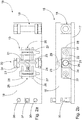
- Figure 2a
- shows a measuring block according to the present invention, viewed from above in a normal loading situation,
- Figure 2b
- shows the measuring block of
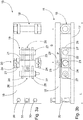
Figure 2a as a side view, - Figure 3a
- shows a measuring block according to the present invention, viewed from above in an overloading situation,
- Figure 3b
- shows the measuring block of
Figure 3a as a side view. -
Figure 1 shows part of the dryer section of a fibre web machine. The dryer section consists of several cylinder groups, each of which containsconsecutive drying cylinders 10 and turnrolls 11. A fabric cycle consisting of afabric 12, here a drying fabric, is supported via the drying cylinders and turn rolls. During production, the fibre web is supported by the fabric and taken via the drying cylinders and turn rolls through the dryer section. The fabric cycle is also supported bybreak back rolls 13, one of which has been equipped here with afabric stretcher 14. In this case, it is possible to keep the fabric at the desired tension. Moreover, the fabric stretcher can be used for loosening the fabric so that it is possible to change the fabric. The secondbreak back roll 13 is supported by themeasuring block 15, and the tension of thefabric 12 can be ascertained from the measurement result of themeasuring block 15. The measured tension can then be used for controlling the fabric stretcher. The measuring block can also be used in connection with fabrics other than a drying fabric. As is known, a measuring block of duplexed measurement is installed at both ends of a break back roll, but even with one measuring block according to the invention at one end of the break back roll, it is possible to obtain duplexed measurement results that correspond to the tension of the fabric. - The invention relates to a measuring block for a fibre web machine. The
measuring block 15 in different situations is presented inFigures 2a - 3b . Themeasuring block 15 includes asupport piece 16 and afastening piece 17, which have been fastened to each other in a pivoting manner by means of ajoint 18. In this case, the support piece and the fastening piece can pivot with respect to each other. Due to the joint, the movement of the support piece and the fastening piece is sensitive but sturdy. The support piece and the fastening piece are thick metal plate pieces, which can endure stresses without bending. In practice, the fastening piece is fastened to the frame of the fibre web machine, and the bearing pedestal of the break back roll that supports the fabric is fastened to the support piece. The measuring block further includes sensor devices 19, which have been adapted between thesupport piece 16 and thefastening piece 17 on themeasuring block 15 in order to determine the tension of a fabric supported by a roll. The forces caused by the fabric and by the mass of the break back roll are transmitted via the measuring block, in which case it is possible to determine the tension of the fabric from the measurement information of the sensor devices. The tension measurement serves as a control variable for the fabric stretcher, in which case it is possible to keep the fabric at the desired tension. Too loose a fabric can cause flutter, and on the other hand excessive tension can damage the fabric. The age of the fabric also has an impact on tension, as does a change in the production conditions. As an example, the fabric stretches as it becomes older, in which case the break back roll is shifted by using the fabric stretcher, and the desired tension is hence achieved. On the other hand, the fabric warms up in a web break, which can increase tension quite rapidly. In this case, the fabric is loosened to avoid damage. - According to the invention, there is a
second support point 20 between thesupport piece 16 and thefastening piece 17, and the sensor devices 19 have been adapted in connection with thesecond support point 20. Due to the joint and the support point, the measuring block is sensitive but stable, and the movement of the support piece is small. Moreover, the sensor devices are located only at the support point, in which case the structure of the joint can be simple but robust. At the same time, the placing of the sensor devices is also freer than earlier. -
Figure 2a presents the measuring block according to the invention viewed from above, andFigure 2b presents it as a side view. Thesupport point 20 consists of anaxle 21, to which abogie 22, which contains the sensor devices 19, has been supported. The axle is functionally a pivot axle. Theaxle 21 itself has been supported to thesupport piece 16 by twoupper lugs 23. Due to thebogie 22, the force is transmitted via the upper lugs 23 from theaxle 21 to thebogie 22, and this balances the support point. At the same time, the force directed at the sensor devices is reduced, in which case it is possible to use smaller sensor devices than earlier. Moreover, the bogie structure equalises the force directed at the sensor devices, in which case the sensor devices function as planned. - The
axle 21 here is a deflecting axle, which has been supported in a floating manner, here to thefastening piece 17. In other words, in a normal situation the force is transmitted from the support piece via the axle to the bogie, but in an overloading situation the deflecting axle deflects, whereby the force is transmitted directly to the fastening piece. The axle of the bogie hence constitutes in itself overloading protection without extra structures and external structures. The arrows at theaxle 21 inFigure 2a illustrate the transmission of the force from theupper lugs 23 to theaxle 21. Correspondingly, the narrower arrows illustrate the transmission of the halved force from thebogie 22 to thefastening piece 17. - From the sensor devices arranged in the bogie, the force is transmitted to the fastening piece. When the force reaches the maximum force permitted for the sensor devices, the deflection of the
axle 21 removes theclearance 25 that has been arranged between theaxle 21 and thelower lug 24 of thefastening piece 17. In this case, the force that exceeds the permitted maximum force is transmitted from the axle directly to the fastening piece. This is illustrated by the arrows inFigure 3a . Theclearance 25 has been implemented simply by a boring in thelower lug 24, which boring is slightly larger than the axle 21 (Figure 2b ). In this case, the clearance is symmetrical, whereby the restriction of the force works irrespective of the direction of the force. The measuring block may hence be subject to either pulling or compression. Correspondingly, the sensor devices function irrespective of the direction of the force. In this case, the measuring block can be placed in a position where the fabric tension pulls the support piece and the fastening piece apart from each other. The measuring block can also be installed upside down or turned 90 degrees, whereby, depending on the position, it is possible to make the measuring range of the sensor devices correspond to the actual load. - In the embodiment presented, the
bogie 22 includes twoend points 26, and the sensor devices 19 have been adapted in one of them or both of them. The bogie is advantageously symmetrical, whereby a force of the same magnitude is directed at both end points. When using an asymmetrical bogie, the magnitudes of the forces are on a ratio to the distances. In this case, the structure of the measuring block can be adapted to the measuring range of the sensor devices by the selection of the end point. The sensor devices 19 include apin sensor 27, with which theend point 26 has been supported to thefastening piece 17. In this case, the pin sensor is also the part that fastens the bogie to the fastening piece, and it serves as a joint, which simplifies the structure of the measuring block. Thefastening piece 17 contains afastening support 28 for the pin sensor. Thebogie 22 is between two fastening supports 28. The structure is low, and the movement of thesupport piece 16 is small. - With the supporting presented, where the joint is at the end of the measuring block, it is possible to choose the location of the support point freely, and hence influence the functioning of the measuring block. In the embodiment presented, the support point is halfway through the measuring block. More generally expressed, the distance S of the
support point 20 from the joint 18 is 25 - 75% of the length L of the measuring block. The dimensions of the bogie can also be changed. In a symmetrical bogie, the length primarily influences the sensitivity of the bogie structure. The shorter the bogie distance, the more sensitive the bogie structure. Generally expressed, the length P of thebogie 22 is 10 - 40% of the length L of the measuring block. The dimension lines are inFigure 3b . - In the application of the figures, the
bogie 22 is symmetrical, and there is a pin sensor at each end point. In this case, a force of the same magnitude and same direction is directed at both end points. In this case, the sensor devices give essentially the same measurement result, which also corresponds to the value that describes the tension of the fabric. Moreover, duplexed sensor devices are created. In this case, if either pin sensor suddenly gives a measurement result that differs from an earlier result, it is immediately obvious that said pin sensor is faulty. In this way, it is possible to ascertain failure without delay, which further increases the reliability of the measuring block. - The force to be measured, directed at the measuring block, is transmitted from the support piece via the joint and the bogie to the fastening piece on a ratio to the distances. In the figures, the support point is centrally, in which case one half of the above-mentioned force comes to the supporting of the bogie. By changing the location of the support point, it is possible to optimise the force to be measured so that it suits the measuring range of the sensor devices, in which case a highly comprehensive variation of measurement applications can be obtained by changing the sensor type.
- Here, the symmetrical bogie further equalises the force, in which case the one quarter of the original force that loads the support piece is directed at the end points. In this case, it is possible to use clearly smaller sensor devices than earlier. At the same time, the mechanical structure always transmits the force in a similar manner, which means that the measurement results of the sensor devices can be used for easily determining the actual loading force. The sensor devices have been placed symmetrically on both sides of the axle. In this case, individual pin sensors measure the same force, which is divided in equal proportions on the pin sensors. The same mechanical structure can be used with duplexed sensor devices or without duplexing, by replacing one sensor with a similarly dimensioned pivot pin.
Figure 2a shows twopin sensors 27.Figure 3a shows only onepin sensor 27. There is a pivot pin at oneend point 26 of thebogie 22. - The support piece is fastened to the frame of the fibre web machine. A roll that supports the fabric is fastened in this case to the fastening piece. The support piece and the fastening piece have been supported to each other by means of a joint. In this case, depending on the tension of the fabric, the tension of the fabric can be determined from the change in the mutual position of the support piece and the fastening piece, by using the sensor devices. The measuring block is often placed in hot circumstances, in which case stresses may occur between the parts due to the temperature differences. The stresses can cause an error in the measuring devices. In the invention, the
upper lug 23 has been fastened to thesupport piece 16 by means of apivot pin 29. This avoids the transmission of stresses from the fastening piece to the bogie structure and vice versa. - At the end of the measuring block opposite to the joint 18, there are three
bolts support piece 16. In this case, the twooutermost bolts 30 can be used for enlarging the gap between the support piece and the fastening piece. The bogie structure can hence be relieved, whereby for example the pin sensors can be replaced easily. Correspondingly, thecentre bolt 31 can be used for reducing the gap between the support piece and the fastening piece, by pulling with the bolt. This is needed in a situation where the fabric tension pulls the support piece and the fastening piece apart from each other. By pulling with the bolt, the bogie structure can be relieved again, and the pin sensors can hence be replaced. - The figures do not present the fastening counterparts and the protective cover. In practice, the joint, bogie structure and sensor devices are fully protected, which prevents fouling and renders the measuring block service-free. If the sensor devices fail, they can be replaced without dismantling the structure.
- The measuring block according to the invention accomplishes cost-effective duplexing of the sensor devices. Moreover, the structure of the measuring block is modular. In practice, the same mechanical measuring block functions with or without the duplexing of the sensor devices. Duplexing can be changed easily even after delivery, in either direction. The duplexed sensor devices measure exactly the same force component due to the bogie structure. In this case, it is easy to determine the measurement result. At the same time, there is an internal and simple overloading protection in the measuring block.
- The present invention relates to a measuring block for a fibre web machine, which measuring block (15) includes a support piece (16) and a fastening piece (17), which have been fastened to each other in a pivoting manner by means of a joint (18), as well as sensor devices (19), which have been adapted between the support piece (16) and the fastening piece (17) on the measuring block (15) in order to determine the tension of a fabric supported by a roll. There is a second support point (20) between the support piece (16) and the fastening piece (17), and the sensor devices (19) have been adapted in connection with the second support point (20).
Claims (7)
- A measuring block for a fibre web machine, which measuring block (15) includes a support piece (16) and a fastening piece (17), which have been fastened to each other in a pivoting manner by means of a joint (18), as well as sensor devices (19), which have been adapted between the support piece (16) and the fastening piece (17) on the measuring block (15) in order to determine the tension of a fabric supported by a roll, characterised in that there is a second support point (20) between the support piece (16) and the fastening piece (17), and the sensor devices (19) have been adapted in connection with the second support point (20).
- A measuring block according to claim 1, characterised in that the support point (20) consists of an axle (21), to which a bogie (22), which contains the sensor devices (19), has been supported.
- A measuring block according to claim 2, characterised in that the bogie (22) includes two end points (26), and the sensor devices (19) have been adapted in one of them or both of them.
- A measuring block according to claim 3, characterised in that the sensor devices (19) include a pin sensor (27), with which the end point (26) has been supported to the fastening piece (17).
- A measuring block according to any one of the claims 2 - 4, characterised in that the axle (21) is a deflecting axle, which has been supported in a floating manner to the fastening piece (17) or to the support piece (16).
- A measuring block according to any one of the claims 1 - 5, characterised in that the distance (S) of the support point (20) from the joint (18) is 25 - 75% of the length (L) of the measuring block.
- A measuring block according to any one of the claims 2 - 6, characterised in that the length (P) of the bogie (22) is 10 - 40% of the length (L) of the measuring block.
Applications Claiming Priority (1)
| Application Number | Priority Date | Filing Date | Title |
|---|---|---|---|
| FIU20174127U FI11690U1 (en) | 2017-05-05 | 2017-05-05 | Measurement block for a fiber web machine |
Publications (2)
| Publication Number | Publication Date |
|---|---|
| EP3399293A1 true EP3399293A1 (en) | 2018-11-07 |
| EP3399293B1 EP3399293B1 (en) | 2020-09-16 |
Family
ID=59296630
Family Applications (1)
| Application Number | Title | Priority Date | Filing Date |
|---|---|---|---|
| EP18168169.3A Active EP3399293B1 (en) | 2017-05-05 | 2018-04-19 | Measuring block for fibre web machine |
Country Status (3)
| Country | Link |
|---|---|
| EP (1) | EP3399293B1 (en) |
| CN (1) | CN108896228B (en) |
| FI (1) | FI11690U1 (en) |
Cited By (1)
| Publication number | Priority date | Publication date | Assignee | Title |
|---|---|---|---|---|
| WO2022161564A1 (en) * | 2021-01-28 | 2022-08-04 | Schaeffler Technologies AG & Co. KG | Force-measuring system |
Citations (3)
| Publication number | Priority date | Publication date | Assignee | Title |
|---|---|---|---|---|
| GB2046454A (en) * | 1979-03-30 | 1980-11-12 | Cleveland Machine Controls | Web tension sensor |
| WO2001020286A1 (en) * | 1999-09-14 | 2001-03-22 | Cleveland Motion Controls, Inc. | Web tension transducer apparatus |
| US6360596B1 (en) * | 1999-08-05 | 2002-03-26 | Cleveland Motion Controls, Inc. | Web tension transducer |
Family Cites Families (14)
| Publication number | Priority date | Publication date | Assignee | Title |
|---|---|---|---|---|
| PL1927834T3 (en) * | 2006-12-02 | 2010-10-29 | Texmag Gmbh Vertriebsgesellschaft | Pulley with force sensor |
| FI120920B (en) * | 2006-12-12 | 2010-04-30 | Abb Oy | Method and system for measuring material web tension |
| US8161826B1 (en) * | 2009-03-05 | 2012-04-24 | Stryker Corporation | Elastically stretchable fabric force sensor arrays and methods of making |
| CH704303B1 (en) * | 2008-04-07 | 2012-06-29 | Urs Meyer | Device i.e. thread tension sensor, for measuring tensile stress on textile thread, has multiple thread guides controlling deflection of thread and acted upon load cell, where zero-point and measuring range are set at device by display |
| CN101463536A (en) * | 2008-11-20 | 2009-06-24 | 张同生 | Tension measurement and control device of beam dyeing machine |
| KR101104939B1 (en) * | 2009-11-12 | 2012-01-13 | 한국기계연구원 | Tension Detector Using Change of Contact Resistance |
| DE102010003504A1 (en) * | 2010-03-31 | 2011-10-06 | Voith Patent Gmbh | A web or strip gauge, use of such a web or strip gauge and method of determining web tension |
| CN101900619A (en) * | 2010-05-13 | 2010-12-01 | 天津工业大学 | Measuring method of weft tension of polyester net loom based on multi-thread |
| CN102069623B (en) * | 2010-10-21 | 2013-11-13 | 李志雄 | Production equipment of film-laminated fiber band and production process thereof |
| US8991263B2 (en) * | 2011-03-08 | 2015-03-31 | The United States Of America As Represented By The Secretary Of The Army | Fiber snubbing clamp using magnetic gripping action |
| CN102914400B (en) * | 2012-10-22 | 2015-02-25 | 江苏万工科技集团有限公司 | Measuring device for fabric tensile force close to cloth fell |
| CN103542969A (en) * | 2013-10-28 | 2014-01-29 | 天津工业大学 | Fabric tension measuring device |
| DE102013222679A1 (en) * | 2013-11-07 | 2015-05-07 | Lindauer Dornier Gesellschaft Mit Beschränkter Haftung | Method of measuring tissue tension in a loom |
| ITUB20154807A1 (en) * | 2015-10-20 | 2017-04-20 | Mesdan Spa | MEASUREMENT DEVICE FOR THE MEASUREMENT OF DYNAMOMETRIC CHARACTERISTICS OF TEXTILE SAMPLES EXTENDED IN THE TYPE OF YARNS, WIRES, TAPES AND THE LIKE. |
-
2017
- 2017-05-05 FI FIU20174127U patent/FI11690U1/en active IP Right Grant
-
2018
- 2018-04-19 EP EP18168169.3A patent/EP3399293B1/en active Active
- 2018-05-07 CN CN201810425001.9A patent/CN108896228B/en active Active
Patent Citations (3)
| Publication number | Priority date | Publication date | Assignee | Title |
|---|---|---|---|---|
| GB2046454A (en) * | 1979-03-30 | 1980-11-12 | Cleveland Machine Controls | Web tension sensor |
| US6360596B1 (en) * | 1999-08-05 | 2002-03-26 | Cleveland Motion Controls, Inc. | Web tension transducer |
| WO2001020286A1 (en) * | 1999-09-14 | 2001-03-22 | Cleveland Motion Controls, Inc. | Web tension transducer apparatus |
Cited By (1)
| Publication number | Priority date | Publication date | Assignee | Title |
|---|---|---|---|---|
| WO2022161564A1 (en) * | 2021-01-28 | 2022-08-04 | Schaeffler Technologies AG & Co. KG | Force-measuring system |
Also Published As
| Publication number | Publication date |
|---|---|
| CN108896228A (en) | 2018-11-27 |
| FI11690U1 (en) | 2017-06-09 |
| EP3399293B1 (en) | 2020-09-16 |
| CN108896228B (en) | 2020-12-18 |
Similar Documents
| Publication | Publication Date | Title |
|---|---|---|
| US4899599A (en) | Strain force sensor means | |
| US5777240A (en) | Load cell and load cell beam assembly | |
| US6920801B2 (en) | Measurement device for measuring radial and/or axial forces | |
| CN105588669B (en) | Axle pin type three-way force cell sensor | |
| CA2586951C (en) | Method and apparatus for bearing thrust monitoring | |
| US2775887A (en) | Load cell type dynamometer with overload protection means | |
| US4118933A (en) | Bearing load indicator | |
| US12251707B2 (en) | Method for monitoring physical conditions of a roller crusher, and a refitting kit for a roller crusher | |
| JP2013516611A (en) | Device for measuring strain in components | |
| EP3399293B1 (en) | Measuring block for fibre web machine | |
| JPH0774766B2 (en) | Measuring device for determining the bearing load of roll bearings | |
| CN109596255A (en) | Measure device, wind-driven generator operation method and the wind-driven generator of wind-driven generator torque | |
| US7971495B2 (en) | Measuring a tensile force | |
| CN106404259A (en) | Force measuring system with dual sensor | |
| EP2500703B1 (en) | Load pin with increased performance | |
| RU2703610C2 (en) | Deformation measurement torsionometer | |
| EP2447198A1 (en) | Roll arrangement | |
| CN110082079A (en) | Standing wire hydraulic steel gate hoisting capacity condition monitoring device | |
| CA2174775C (en) | Improvements in or relating to a consistency transmitter | |
| JP4849457B2 (en) | Load measuring device and work machine | |
| JPS5996336A (en) | Measurer for excavation force of excavator | |
| CN115164948A (en) | A Novel Resistance Strain Load Cell and Measuring Device | |
| EP2620545A1 (en) | Method and arrangement for force measurement in connection with a manufacturing machine | |
| RU2287478C1 (en) | Device for measuring force of tension of load-lifting mechanism load cable | |
| RU2169901C2 (en) | Anchor strain gauge |
Legal Events
| Date | Code | Title | Description |
|---|---|---|---|
| PUAI | Public reference made under article 153(3) epc to a published international application that has entered the european phase |
Free format text: ORIGINAL CODE: 0009012 |
|
| STAA | Information on the status of an ep patent application or granted ep patent |
Free format text: STATUS: THE APPLICATION HAS BEEN PUBLISHED |
|
| AK | Designated contracting states |
Kind code of ref document: A1 Designated state(s): AL AT BE BG CH CY CZ DE DK EE ES FI FR GB GR HR HU IE IS IT LI LT LU LV MC MK MT NL NO PL PT RO RS SE SI SK SM TR |
|
| AX | Request for extension of the european patent |
Extension state: BA ME |
|
| STAA | Information on the status of an ep patent application or granted ep patent |
Free format text: STATUS: REQUEST FOR EXAMINATION WAS MADE |
|
| 17P | Request for examination filed |
Effective date: 20181127 |
|
| RBV | Designated contracting states (corrected) |
Designated state(s): AL AT BE BG CH CY CZ DE DK EE ES FI FR GB GR HR HU IE IS IT LI LT LU LV MC MK MT NL NO PL PT RO RS SE SI SK SM TR |
|
| STAA | Information on the status of an ep patent application or granted ep patent |
Free format text: STATUS: EXAMINATION IS IN PROGRESS |
|
| 17Q | First examination report despatched |
Effective date: 20190517 |
|
| GRAP | Despatch of communication of intention to grant a patent |
Free format text: ORIGINAL CODE: EPIDOSNIGR1 |
|
| STAA | Information on the status of an ep patent application or granted ep patent |
Free format text: STATUS: GRANT OF PATENT IS INTENDED |
|
| RIC1 | Information provided on ipc code assigned before grant |
Ipc: B65H 23/195 20060101ALI20200227BHEP Ipc: D21F 7/00 20060101ALI20200227BHEP Ipc: D21G 9/00 20060101ALI20200227BHEP Ipc: G01L 5/10 20200101AFI20200227BHEP Ipc: D21F 2/00 20060101ALI20200227BHEP Ipc: G01L 5/107 20200101ALI20200227BHEP Ipc: B65H 23/04 20060101ALI20200227BHEP |
|
| INTG | Intention to grant announced |
Effective date: 20200317 |
|
| GRAS | Grant fee paid |
Free format text: ORIGINAL CODE: EPIDOSNIGR3 |
|
| GRAA | (expected) grant |
Free format text: ORIGINAL CODE: 0009210 |
|
| STAA | Information on the status of an ep patent application or granted ep patent |
Free format text: STATUS: THE PATENT HAS BEEN GRANTED |
|
| AK | Designated contracting states |
Kind code of ref document: B1 Designated state(s): AL AT BE BG CH CY CZ DE DK EE ES FI FR GB GR HR HU IE IS IT LI LT LU LV MC MK MT NL NO PL PT RO RS SE SI SK SM TR |
|
| REG | Reference to a national code |
Ref country code: GB Ref legal event code: FG4D |
|
| REG | Reference to a national code |
Ref country code: CH Ref legal event code: EP |
|
| REG | Reference to a national code |
Ref country code: DE Ref legal event code: R096 Ref document number: 602018007802 Country of ref document: DE |
|
| REG | Reference to a national code |
Ref country code: IE Ref legal event code: FG4D |
|
| REG | Reference to a national code |
Ref country code: AT Ref legal event code: REF Ref document number: 1314582 Country of ref document: AT Kind code of ref document: T Effective date: 20201015 |
|
| PG25 | Lapsed in a contracting state [announced via postgrant information from national office to epo] |
Ref country code: BG Free format text: LAPSE BECAUSE OF FAILURE TO SUBMIT A TRANSLATION OF THE DESCRIPTION OR TO PAY THE FEE WITHIN THE PRESCRIBED TIME-LIMIT Effective date: 20201216 Ref country code: HR Free format text: LAPSE BECAUSE OF FAILURE TO SUBMIT A TRANSLATION OF THE DESCRIPTION OR TO PAY THE FEE WITHIN THE PRESCRIBED TIME-LIMIT Effective date: 20200916 Ref country code: NO Free format text: LAPSE BECAUSE OF FAILURE TO SUBMIT A TRANSLATION OF THE DESCRIPTION OR TO PAY THE FEE WITHIN THE PRESCRIBED TIME-LIMIT Effective date: 20201216 Ref country code: GR Free format text: LAPSE BECAUSE OF FAILURE TO SUBMIT A TRANSLATION OF THE DESCRIPTION OR TO PAY THE FEE WITHIN THE PRESCRIBED TIME-LIMIT Effective date: 20201217 Ref country code: FI Free format text: LAPSE BECAUSE OF FAILURE TO SUBMIT A TRANSLATION OF THE DESCRIPTION OR TO PAY THE FEE WITHIN THE PRESCRIBED TIME-LIMIT Effective date: 20200916 Ref country code: SE Free format text: LAPSE BECAUSE OF FAILURE TO SUBMIT A TRANSLATION OF THE DESCRIPTION OR TO PAY THE FEE WITHIN THE PRESCRIBED TIME-LIMIT Effective date: 20200916 |
|
| REG | Reference to a national code |
Ref country code: NL Ref legal event code: MP Effective date: 20200916 |
|
| PG25 | Lapsed in a contracting state [announced via postgrant information from national office to epo] |
Ref country code: LV Free format text: LAPSE BECAUSE OF FAILURE TO SUBMIT A TRANSLATION OF THE DESCRIPTION OR TO PAY THE FEE WITHIN THE PRESCRIBED TIME-LIMIT Effective date: 20200916 Ref country code: RS Free format text: LAPSE BECAUSE OF FAILURE TO SUBMIT A TRANSLATION OF THE DESCRIPTION OR TO PAY THE FEE WITHIN THE PRESCRIBED TIME-LIMIT Effective date: 20200916 |
|
| REG | Reference to a national code |
Ref country code: LT Ref legal event code: MG4D |
|
| PG25 | Lapsed in a contracting state [announced via postgrant information from national office to epo] |
Ref country code: SM Free format text: LAPSE BECAUSE OF FAILURE TO SUBMIT A TRANSLATION OF THE DESCRIPTION OR TO PAY THE FEE WITHIN THE PRESCRIBED TIME-LIMIT Effective date: 20200916 Ref country code: LT Free format text: LAPSE BECAUSE OF FAILURE TO SUBMIT A TRANSLATION OF THE DESCRIPTION OR TO PAY THE FEE WITHIN THE PRESCRIBED TIME-LIMIT Effective date: 20200916 Ref country code: CZ Free format text: LAPSE BECAUSE OF FAILURE TO SUBMIT A TRANSLATION OF THE DESCRIPTION OR TO PAY THE FEE WITHIN THE PRESCRIBED TIME-LIMIT Effective date: 20200916 Ref country code: PT Free format text: LAPSE BECAUSE OF FAILURE TO SUBMIT A TRANSLATION OF THE DESCRIPTION OR TO PAY THE FEE WITHIN THE PRESCRIBED TIME-LIMIT Effective date: 20210118 Ref country code: RO Free format text: LAPSE BECAUSE OF FAILURE TO SUBMIT A TRANSLATION OF THE DESCRIPTION OR TO PAY THE FEE WITHIN THE PRESCRIBED TIME-LIMIT Effective date: 20200916 Ref country code: EE Free format text: LAPSE BECAUSE OF FAILURE TO SUBMIT A TRANSLATION OF THE DESCRIPTION OR TO PAY THE FEE WITHIN THE PRESCRIBED TIME-LIMIT Effective date: 20200916 |
|
| PG25 | Lapsed in a contracting state [announced via postgrant information from national office to epo] |
Ref country code: PL Free format text: LAPSE BECAUSE OF FAILURE TO SUBMIT A TRANSLATION OF THE DESCRIPTION OR TO PAY THE FEE WITHIN THE PRESCRIBED TIME-LIMIT Effective date: 20200916 Ref country code: IS Free format text: LAPSE BECAUSE OF FAILURE TO SUBMIT A TRANSLATION OF THE DESCRIPTION OR TO PAY THE FEE WITHIN THE PRESCRIBED TIME-LIMIT Effective date: 20210116 Ref country code: AL Free format text: LAPSE BECAUSE OF FAILURE TO SUBMIT A TRANSLATION OF THE DESCRIPTION OR TO PAY THE FEE WITHIN THE PRESCRIBED TIME-LIMIT Effective date: 20200916 Ref country code: ES Free format text: LAPSE BECAUSE OF FAILURE TO SUBMIT A TRANSLATION OF THE DESCRIPTION OR TO PAY THE FEE WITHIN THE PRESCRIBED TIME-LIMIT Effective date: 20200916 |
|
| REG | Reference to a national code |
Ref country code: DE Ref legal event code: R097 Ref document number: 602018007802 Country of ref document: DE |
|
| PG25 | Lapsed in a contracting state [announced via postgrant information from national office to epo] |
Ref country code: SK Free format text: LAPSE BECAUSE OF FAILURE TO SUBMIT A TRANSLATION OF THE DESCRIPTION OR TO PAY THE FEE WITHIN THE PRESCRIBED TIME-LIMIT Effective date: 20200916 |
|
| PLBE | No opposition filed within time limit |
Free format text: ORIGINAL CODE: 0009261 |
|
| STAA | Information on the status of an ep patent application or granted ep patent |
Free format text: STATUS: NO OPPOSITION FILED WITHIN TIME LIMIT |
|
| 26N | No opposition filed |
Effective date: 20210617 |
|
| PG25 | Lapsed in a contracting state [announced via postgrant information from national office to epo] |
Ref country code: DK Free format text: LAPSE BECAUSE OF FAILURE TO SUBMIT A TRANSLATION OF THE DESCRIPTION OR TO PAY THE FEE WITHIN THE PRESCRIBED TIME-LIMIT Effective date: 20200916 Ref country code: SI Free format text: LAPSE BECAUSE OF FAILURE TO SUBMIT A TRANSLATION OF THE DESCRIPTION OR TO PAY THE FEE WITHIN THE PRESCRIBED TIME-LIMIT Effective date: 20200916 |
|
| PG25 | Lapsed in a contracting state [announced via postgrant information from national office to epo] |
Ref country code: MC Free format text: LAPSE BECAUSE OF FAILURE TO SUBMIT A TRANSLATION OF THE DESCRIPTION OR TO PAY THE FEE WITHIN THE PRESCRIBED TIME-LIMIT Effective date: 20200916 |
|
| PG25 | Lapsed in a contracting state [announced via postgrant information from national office to epo] |
Ref country code: LU Free format text: LAPSE BECAUSE OF NON-PAYMENT OF DUE FEES Effective date: 20210419 |
|
| REG | Reference to a national code |
Ref country code: BE Ref legal event code: MM Effective date: 20210430 |
|
| PG25 | Lapsed in a contracting state [announced via postgrant information from national office to epo] |
Ref country code: FR Free format text: LAPSE BECAUSE OF NON-PAYMENT OF DUE FEES Effective date: 20210430 Ref country code: LI Free format text: LAPSE BECAUSE OF NON-PAYMENT OF DUE FEES Effective date: 20210430 Ref country code: CH Free format text: LAPSE BECAUSE OF NON-PAYMENT OF DUE FEES Effective date: 20210430 |
|
| PG25 | Lapsed in a contracting state [announced via postgrant information from national office to epo] |
Ref country code: IE Free format text: LAPSE BECAUSE OF NON-PAYMENT OF DUE FEES Effective date: 20210419 |
|
| PG25 | Lapsed in a contracting state [announced via postgrant information from national office to epo] |
Ref country code: IS Free format text: LAPSE BECAUSE OF FAILURE TO SUBMIT A TRANSLATION OF THE DESCRIPTION OR TO PAY THE FEE WITHIN THE PRESCRIBED TIME-LIMIT Effective date: 20210116 |
|
| PG25 | Lapsed in a contracting state [announced via postgrant information from national office to epo] |
Ref country code: BE Free format text: LAPSE BECAUSE OF NON-PAYMENT OF DUE FEES Effective date: 20210430 |
|
| GBPC | Gb: european patent ceased through non-payment of renewal fee |
Effective date: 20220419 |
|
| PG25 | Lapsed in a contracting state [announced via postgrant information from national office to epo] |
Ref country code: GB Free format text: LAPSE BECAUSE OF NON-PAYMENT OF DUE FEES Effective date: 20220419 |
|
| PG25 | Lapsed in a contracting state [announced via postgrant information from national office to epo] |
Ref country code: NL Free format text: LAPSE BECAUSE OF NON-PAYMENT OF DUE FEES Effective date: 20200923 Ref country code: CY Free format text: LAPSE BECAUSE OF FAILURE TO SUBMIT A TRANSLATION OF THE DESCRIPTION OR TO PAY THE FEE WITHIN THE PRESCRIBED TIME-LIMIT Effective date: 20200916 |
|
| PG25 | Lapsed in a contracting state [announced via postgrant information from national office to epo] |
Ref country code: HU Free format text: LAPSE BECAUSE OF FAILURE TO SUBMIT A TRANSLATION OF THE DESCRIPTION OR TO PAY THE FEE WITHIN THE PRESCRIBED TIME-LIMIT; INVALID AB INITIO Effective date: 20180419 |
|
| PG25 | Lapsed in a contracting state [announced via postgrant information from national office to epo] |
Ref country code: MK Free format text: LAPSE BECAUSE OF FAILURE TO SUBMIT A TRANSLATION OF THE DESCRIPTION OR TO PAY THE FEE WITHIN THE PRESCRIBED TIME-LIMIT Effective date: 20200916 |
|
| PG25 | Lapsed in a contracting state [announced via postgrant information from national office to epo] |
Ref country code: MT Free format text: LAPSE BECAUSE OF FAILURE TO SUBMIT A TRANSLATION OF THE DESCRIPTION OR TO PAY THE FEE WITHIN THE PRESCRIBED TIME-LIMIT Effective date: 20200916 |
|
| REG | Reference to a national code |
Ref country code: AT Ref legal event code: UEP Ref document number: 1314582 Country of ref document: AT Kind code of ref document: T Effective date: 20200916 |
|
| PGFP | Annual fee paid to national office [announced via postgrant information from national office to epo] |
Ref country code: DE Payment date: 20250422 Year of fee payment: 8 |
|
| PGFP | Annual fee paid to national office [announced via postgrant information from national office to epo] |
Ref country code: IT Payment date: 20250424 Year of fee payment: 8 |
|
| PGFP | Annual fee paid to national office [announced via postgrant information from national office to epo] |
Ref country code: AT Payment date: 20250423 Year of fee payment: 8 |
|
| PG25 | Lapsed in a contracting state [announced via postgrant information from national office to epo] |
Ref country code: TR Free format text: LAPSE BECAUSE OF FAILURE TO SUBMIT A TRANSLATION OF THE DESCRIPTION OR TO PAY THE FEE WITHIN THE PRESCRIBED TIME-LIMIT Effective date: 20200916 |