EP3399172A1 - Gas engine system - Google Patents
Gas engine system Download PDFInfo
- Publication number
- EP3399172A1 EP3399172A1 EP16881664.3A EP16881664A EP3399172A1 EP 3399172 A1 EP3399172 A1 EP 3399172A1 EP 16881664 A EP16881664 A EP 16881664A EP 3399172 A1 EP3399172 A1 EP 3399172A1
- Authority
- EP
- European Patent Office
- Prior art keywords
- passage
- gas engine
- intake
- cylinders
- pressure
- Prior art date
- Legal status (The legal status is an assumption and is not a legal conclusion. Google has not performed a legal analysis and makes no representation as to the accuracy of the status listed.)
- Withdrawn
Links
Images

Classifications
-
- F—MECHANICAL ENGINEERING; LIGHTING; HEATING; WEAPONS; BLASTING
- F02—COMBUSTION ENGINES; HOT-GAS OR COMBUSTION-PRODUCT ENGINE PLANTS
- F02B—INTERNAL-COMBUSTION PISTON ENGINES; COMBUSTION ENGINES IN GENERAL
- F02B37/00—Engines characterised by provision of pumps driven at least for part of the time by exhaust
- F02B37/12—Control of the pumps
- F02B37/16—Control of the pumps by bypassing charging air
-
- F—MECHANICAL ENGINEERING; LIGHTING; HEATING; WEAPONS; BLASTING
- F02—COMBUSTION ENGINES; HOT-GAS OR COMBUSTION-PRODUCT ENGINE PLANTS
- F02B—INTERNAL-COMBUSTION PISTON ENGINES; COMBUSTION ENGINES IN GENERAL
- F02B37/00—Engines characterised by provision of pumps driven at least for part of the time by exhaust
-
- F—MECHANICAL ENGINEERING; LIGHTING; HEATING; WEAPONS; BLASTING
- F02—COMBUSTION ENGINES; HOT-GAS OR COMBUSTION-PRODUCT ENGINE PLANTS
- F02B—INTERNAL-COMBUSTION PISTON ENGINES; COMBUSTION ENGINES IN GENERAL
- F02B37/00—Engines characterised by provision of pumps driven at least for part of the time by exhaust
- F02B37/12—Control of the pumps
-
- F—MECHANICAL ENGINEERING; LIGHTING; HEATING; WEAPONS; BLASTING
- F02—COMBUSTION ENGINES; HOT-GAS OR COMBUSTION-PRODUCT ENGINE PLANTS
- F02D—CONTROLLING COMBUSTION ENGINES
- F02D19/00—Controlling engines characterised by their use of non-liquid fuels, pluralities of fuels, or non-fuel substances added to the combustible mixtures
- F02D19/02—Controlling engines characterised by their use of non-liquid fuels, pluralities of fuels, or non-fuel substances added to the combustible mixtures peculiar to engines working with gaseous fuels
-
- F—MECHANICAL ENGINEERING; LIGHTING; HEATING; WEAPONS; BLASTING
- F02—COMBUSTION ENGINES; HOT-GAS OR COMBUSTION-PRODUCT ENGINE PLANTS
- F02D—CONTROLLING COMBUSTION ENGINES
- F02D41/00—Electrical control of supply of combustible mixture or its constituents
- F02D41/0002—Controlling intake air
- F02D41/0007—Controlling intake air for control of turbo-charged or super-charged engines
-
- F—MECHANICAL ENGINEERING; LIGHTING; HEATING; WEAPONS; BLASTING
- F02—COMBUSTION ENGINES; HOT-GAS OR COMBUSTION-PRODUCT ENGINE PLANTS
- F02D—CONTROLLING COMBUSTION ENGINES
- F02D41/00—Electrical control of supply of combustible mixture or its constituents
- F02D41/0025—Controlling engines characterised by use of non-liquid fuels, pluralities of fuels, or non-fuel substances added to the combustible mixtures
- F02D41/0027—Controlling engines characterised by use of non-liquid fuels, pluralities of fuels, or non-fuel substances added to the combustible mixtures the fuel being gaseous
-
- F—MECHANICAL ENGINEERING; LIGHTING; HEATING; WEAPONS; BLASTING
- F02—COMBUSTION ENGINES; HOT-GAS OR COMBUSTION-PRODUCT ENGINE PLANTS
- F02M—SUPPLYING COMBUSTION ENGINES IN GENERAL WITH COMBUSTIBLE MIXTURES OR CONSTITUENTS THEREOF
- F02M21/00—Apparatus for supplying engines with non-liquid fuels, e.g. gaseous fuels stored in liquid form
- F02M21/02—Apparatus for supplying engines with non-liquid fuels, e.g. gaseous fuels stored in liquid form for gaseous fuels
-
- F—MECHANICAL ENGINEERING; LIGHTING; HEATING; WEAPONS; BLASTING
- F02—COMBUSTION ENGINES; HOT-GAS OR COMBUSTION-PRODUCT ENGINE PLANTS
- F02B—INTERNAL-COMBUSTION PISTON ENGINES; COMBUSTION ENGINES IN GENERAL
- F02B33/00—Engines characterised by provision of pumps for charging or scavenging
- F02B33/44—Passages conducting the charge from the pump to the engine inlet, e.g. reservoirs
-
- F—MECHANICAL ENGINEERING; LIGHTING; HEATING; WEAPONS; BLASTING
- F02—COMBUSTION ENGINES; HOT-GAS OR COMBUSTION-PRODUCT ENGINE PLANTS
- F02D—CONTROLLING COMBUSTION ENGINES
- F02D2250/00—Engine control related to specific problems or objectives
- F02D2250/41—Control to generate negative pressure in the intake manifold, e.g. for fuel vapor purging or brake booster
-
- Y—GENERAL TAGGING OF NEW TECHNOLOGICAL DEVELOPMENTS; GENERAL TAGGING OF CROSS-SECTIONAL TECHNOLOGIES SPANNING OVER SEVERAL SECTIONS OF THE IPC; TECHNICAL SUBJECTS COVERED BY FORMER USPC CROSS-REFERENCE ART COLLECTIONS [XRACs] AND DIGESTS
- Y02—TECHNOLOGIES OR APPLICATIONS FOR MITIGATION OR ADAPTATION AGAINST CLIMATE CHANGE
- Y02T—CLIMATE CHANGE MITIGATION TECHNOLOGIES RELATED TO TRANSPORTATION
- Y02T10/00—Road transport of goods or passengers
- Y02T10/10—Internal combustion engine [ICE] based vehicles
- Y02T10/12—Improving ICE efficiencies
-
- Y—GENERAL TAGGING OF NEW TECHNOLOGICAL DEVELOPMENTS; GENERAL TAGGING OF CROSS-SECTIONAL TECHNOLOGIES SPANNING OVER SEVERAL SECTIONS OF THE IPC; TECHNICAL SUBJECTS COVERED BY FORMER USPC CROSS-REFERENCE ART COLLECTIONS [XRACs] AND DIGESTS
- Y02—TECHNOLOGIES OR APPLICATIONS FOR MITIGATION OR ADAPTATION AGAINST CLIMATE CHANGE
- Y02T—CLIMATE CHANGE MITIGATION TECHNOLOGIES RELATED TO TRANSPORTATION
- Y02T10/00—Road transport of goods or passengers
- Y02T10/10—Internal combustion engine [ICE] based vehicles
- Y02T10/30—Use of alternative fuels, e.g. biofuels
Definitions
- the present invention relates to a gas engine system including a gas engine.
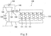
- Patent Literature 1 discloses a gas engine system 100 including a turbocharger 120 and a gas engine 110 as shown in Fig. 3 .
- a plurality of cylinders 111 of the gas engine 110 are connected to a compressor 121 of the turbocharger 120 by an intake passage 101, and are connected to a turbine 122 of the turbocharger 120 by an exhaust passage 102.
- the intake passage 101 is provided with a throttle valve 130.
- a circulation passage 140 branches off from the intake passage 101 at a position downstream of the throttle valve 130, and the circulation passage 140 is connected to a suction passage 160, which leads air to the compressor 121.
- the circulation passage 140 is provided with a circulation valve 150.
- opening degree control of the throttle valve 130 is performed.
- the opening degree of the throttle valve 130 is set to a predetermined opening degree, and opening degree control of the circulation valve 150 is performed.
- each of the aforementioned terms “low load range” and “middle/high load range” is considered to indicate a state where the gas engine is performing work.
- the turbocharger barely functions, and the intake pressure to the gas engine becomes substantially the atmospheric pressure.
- the inventors of the present invention have found, as a result of diligent studies, that when the intake pressure becomes substantially the atmospheric pressure during idling, an air-fuel mixture of a fuel gas and air becomes too lean. When the air-fuel mixture becomes too lean, the combustion becomes unstable, and as a result, the fuel gas that is uncombusted is discharged.
- an object of the present invention is to provide a gas engine system capable of preventing an air-fuel mixture from becoming too lean during idling.
- a gas engine system includes: a gas engine including a plurality of cylinders; a turbocharger including a compressor and a turbine, the compressor being connected to the plurality of cylinders by an intake passage, the turbine being connected to the plurality of cylinders by an exhaust passage; a throttle valve provided on the intake passage; a bleed valve provided on a branch passage that branches off from the intake passage; and a controller that controls the throttle valve and the bleed valve. The controller determines whether or not an idling condition is satisfied.
- the controller when the idling condition is satisfied, fully closes the bleed valve and controls the throttle valve such that an intake pressure, which is a pressure of air supplied to the plurality of cylinders, is a negative pressure; and when the idling condition is not satisfied, keeps an opening degree of the throttle valve to a predetermined opening degree, and controls the bleed valve such that the intake pressure is a target pressure.
- the intake pressure can be adjusted by using the bleed valve. Accordingly, surging is less likely to occur compared to a case where the intake pressure is adjusted by the throttle valve, and intake pressure responsiveness can be made high.
- the intake pressure to the gas engine is adjusted to be a negative pressure. Accordingly, the amount of air introduced into each cylinder is reduced. This makes it possible to prevent an air-fuel mixture from becoming too lean during idling.
- the bleed valve is fully closed during idling, air can be prevented from flowing into the intake passage in the negative-pressure state through the branch passage.
- the gas engine may include a plurality of fuel injection valves corresponding to the plurality of cylinders, respectively, and the branch passage may branch off from the intake passage at a position upstream of the plurality of fuel injection valves. According to this configuration, in a case where the branch passage releases part of intake air to the atmosphere, there is no risk of the fuel being discharged to the outside. This is advantageous in terms of fuel efficiency.
- the above gas engine system may further include an air cooler provided on the intake passage.
- the branch passage may branch off from the intake passage at a position downstream of the air cooler, and may release part of intake air flowing through the intake passage to an atmosphere. According to this configuration, part of the intake air, the temperature of which has become low, can be released to the atmosphere.
- the present invention makes it possible to prevent the air-fuel mixture from becoming too lean during idling.
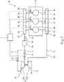
- Fig. 1 shows a gas engine system 1A according to one embodiment of the present invention.
- the system 1A includes an Otto-cycle gas engine 4, a turbocharger 2, and a controller 7.
- the gas engine 4 may be a pure gas engine that combusts only a fuel gas (e.g., natural gas), or may be a dual fuel engine that combusts one of or both a fuel gas and a fuel oil.
- the cycle of the gas engine 4 may be a diesel cycle.
- the gas engine 4 is a 4-stroke engine.
- the gas engine 4 may be a 2-stroke engine.
- the gas engine 4 is used as a main engine of a ship.
- the gas engine 4 may directly drive a screw propeller to rotate, or may drive the screw propeller to rotate via a power generator and a motor.
- the gas engine 4 may be incorporated in power generating equipment installed on the ground.
- the gas engine 4 includes a plurality of cylinders 41.
- the number of cylinders 41 is 5 to 18, for example ( Fig. 1 shows only three cylinders 41 for the purpose of simplifying the drawing).
- the gas engine 4 is provided with a plurality of fuel injection valves 42 corresponding to the plurality of cylinders 41, respectively.
- Each fuel injection valve 42 injects a fuel gas into air supplied to the corresponding cylinder 41, thereby generating an air-fuel mixture of the fuel gas and the air.
- the air-fuel mixture is ignited in the cylinder 41, and thus combusted.
- the turbocharger 2 includes a compressor 21 and a turbine 22.
- the compressor 21 is connected to the cylinders 41 by an intake passage 3, and the turbine 22 is connected to the cylinders 41 by an exhaust passage 5. Air from the outside of the system is led to the compressor 21 through a suction passage 11, and exhaust gas from the turbine 22 is led to the outside of the system through an exhaust passage 12.
- the intake passage 3 includes: an intake manifold 32; a main passage 31, which connects the intake manifold 32 and the compressor 21; and a plurality of branch passages 33, which connect the intake manifold 32 and the cylinders 41.
- the exhaust passage 5 includes: an exhaust manifold 52; a plurality of branch passages 51, which connect the cylinders 41 and the exhaust manifold 52; and a main passage 53, which connects the exhaust manifold 52 and the turbine 22.
- the main passage 31 of the intake passage 3 is provided with a throttle valve 34 and an air cooler 35, such that the throttle valve 34 and the air cooler 35 are arranged in this order from the upstream side.
- the main passage 31 is provided with a pressure sensor 71, which detects the intake pressure to the gas engine 4 (the pressure of air supplied to the cylinders 41).
- the pressure sensor 71 is positioned downstream of a branching position of a branch passage 6 described below.
- the branch passage 6 branches off from the main passage 31 of the intake passage 3.
- the branch passage 6 serves to release compressed air compressed by the compressor 21 from the intake passage 3.
- the branch passage 6 branches off from the main passage 31 at a position downstream of the air cooler 35.
- the distal end (downstream end) of the branch passage 6 is open to the atmosphere. That is, the branch passage 6 releases part of intake air flowing through the main passage 31 of the intake passage 3 to the atmosphere.
- the branch passage 6 is provided with a bleed valve 61.
- the above-described fuel injection valves 42, the throttle valve 34, and the bleed valve 61 are controlled by the controller 7.
- the controller 7 starts/ends the injection of the fuel gas from each fuel injection valve 42 at predetermined timings based on the crank angle of the gas engine 4.
- the controller 7 For the control of the throttle valve 34 and the bleed valve 61, the controller 7 first determines whether or not an idling condition is satisfied.
- the idling condition is at least one of the conditions (A) and (B) indicated below.
- condition (C) indicated below may be adopted instead of the above condition (B).
- the controller 7 keeps the opening degree of the throttle valve 34 to a predetermined opening degree.
- the predetermined opening degree is desirably not less than 75%, and more desirably, not less than 90%.
- the predetermined opening degree may be 100% (i.e., the throttle valve 34 being fully open).
- the controller 7 controls the bleed valve 61 such that the intake pressure detected by the pressure sensor 71 is a required pressure of the gas engine 4. That is, the flow rate of air released from the intake passage 3 through the branch passage 6 is adjusted by the opening degree of the bleed valve 61.
- the controller 7 when the idling condition is satisfied, i.e., during idling, the controller 7 fully closes the bleed valve 61, and controls the throttle valve 34 such that the intake pressure to the gas engine 4 is a negative pressure.
- the controller 7 changes the opening degree of the throttle valve 34 to such a preset opening degree that the intake pressure to the gas engine 4 is a negative pressure.
- the intake pressure can be adjusted by using the bleed valve 61. Accordingly, surging is less likely to occur compared to a case where the intake pressure is adjusted by the throttle valve 34, and intake pressure responsiveness can be made high.
- the intake pressure to the gas engine 4 is adjusted to be a negative pressure. Accordingly, the amount of air introduced into each cylinder 41 is reduced. This makes it possible to prevent the air-fuel mixture from becoming too lean during idling.
- the bleed valve 61 is fully closed during idling, air can be prevented from flowing into the intake passage 3 in the negative-pressure state through the branch passage 6.
- branch passage 6 branches off from the intake passage 3 at a position upstream of the fuel injection valves 42. Therefore, in a case where the branch passage 6 releases part of the intake air to the atmosphere as in the present embodiment, there is no risk of the fuel being discharged to the outside. This is advantageous in terms of fuel efficiency.
- the distal end (downstream end) of the branch passage 6 may be connected to the suction passage 11.
- the branch passage 6 may branch off from the main passage 31 of the intake passage 3 at a position upstream of the air cooler 35.
- the bleed valve 61 a valve that is capable of bearing the discharge temperature of the compressor 21, which is a high-temperature (e.g., 200°C).
- a high-temperature e.g. 200°C
- an inexpensive valve can be used as the bleed valve 61.
Landscapes
- Engineering & Computer Science (AREA)
- Chemical & Material Sciences (AREA)
- Combustion & Propulsion (AREA)
- Mechanical Engineering (AREA)
- General Engineering & Computer Science (AREA)
- Chemical Kinetics & Catalysis (AREA)
- General Chemical & Material Sciences (AREA)
- Oil, Petroleum & Natural Gas (AREA)
- Output Control And Ontrol Of Special Type Engine (AREA)
- Electrical Control Of Air Or Fuel Supplied To Internal-Combustion Engine (AREA)
- Supercharger (AREA)
- Control Of Vehicle Engines Or Engines For Specific Uses (AREA)
Abstract
Description
- The present invention relates to a gas engine system including a gas engine.
- Generally speaking, Otto-cycle gas engines are operated under lean-bum conditions. Also, a gas engine is often used with a turbocharger. For example, Patent Literature 1 discloses a
gas engine system 100 including aturbocharger 120 and agas engine 110 as shown inFig. 3 . - Specifically, a plurality of
cylinders 111 of thegas engine 110 are connected to acompressor 121 of theturbocharger 120 by anintake passage 101, and are connected to a turbine 122 of theturbocharger 120 by anexhaust passage 102. Theintake passage 101 is provided with athrottle valve 130. Acirculation passage 140 branches off from theintake passage 101 at a position downstream of thethrottle valve 130, and thecirculation passage 140 is connected to asuction passage 160, which leads air to thecompressor 121. Thecirculation passage 140 is provided with acirculation valve 150. - In the
gas engine system 100, when the engine load is in a low load range, opening degree control of thethrottle valve 130 is performed. On the other hand, when the engine load is in a middle/high load range, the opening degree of thethrottle valve 130 is set to a predetermined opening degree, and opening degree control of thecirculation valve 150 is performed. - PTL 1: Japanese Laid-Open Patent Application Publication No.
2015-161201 - Each of the aforementioned terms "low load range" and "middle/high load range" is considered to indicate a state where the gas engine is performing work. During idling, in which the gas engine performs no work (e.g., while a clutch interposed between the output shaft of the gas engine and a driven body is disengaged), the turbocharger barely functions, and the intake pressure to the gas engine becomes substantially the atmospheric pressure. However, the inventors of the present invention have found, as a result of diligent studies, that when the intake pressure becomes substantially the atmospheric pressure during idling, an air-fuel mixture of a fuel gas and air becomes too lean. When the air-fuel mixture becomes too lean, the combustion becomes unstable, and as a result, the fuel gas that is uncombusted is discharged.
- In view of the above, an object of the present invention is to provide a gas engine system capable of preventing an air-fuel mixture from becoming too lean during idling.
- In order to solve the above-described problems, a gas engine system according to the present invention includes: a gas engine including a plurality of cylinders; a turbocharger including a compressor and a turbine, the compressor being connected to the plurality of cylinders by an intake passage, the turbine being connected to the plurality of cylinders by an exhaust passage; a throttle valve provided on the intake passage; a bleed valve provided on a branch passage that branches off from the intake passage; and a controller that controls the throttle valve and the bleed valve. The controller determines whether or not an idling condition is satisfied. The controller: when the idling condition is satisfied, fully closes the bleed valve and controls the throttle valve such that an intake pressure, which is a pressure of air supplied to the plurality of cylinders, is a negative pressure; and when the idling condition is not satisfied, keeps an opening degree of the throttle valve to a predetermined opening degree, and controls the bleed valve such that the intake pressure is a target pressure.
- According to the above configuration, when the idling condition is not satisfied (i.e., during normal operation), the intake pressure can be adjusted by using the bleed valve. Accordingly, surging is less likely to occur compared to a case where the intake pressure is adjusted by the throttle valve, and intake pressure responsiveness can be made high. On the other hand, when the idling condition is satisfied (i.e., during idling), the intake pressure to the gas engine is adjusted to be a negative pressure. Accordingly, the amount of air introduced into each cylinder is reduced. This makes it possible to prevent an air-fuel mixture from becoming too lean during idling. Moreover, since the bleed valve is fully closed during idling, air can be prevented from flowing into the intake passage in the negative-pressure state through the branch passage.
- The gas engine may include a plurality of fuel injection valves corresponding to the plurality of cylinders, respectively, and the branch passage may branch off from the intake passage at a position upstream of the plurality of fuel injection valves. According to this configuration, in a case where the branch passage releases part of intake air to the atmosphere, there is no risk of the fuel being discharged to the outside. This is advantageous in terms of fuel efficiency.
- The above gas engine system may further include an air cooler provided on the intake passage. The branch passage may branch off from the intake passage at a position downstream of the air cooler, and may release part of intake air flowing through the intake passage to an atmosphere. According to this configuration, part of the intake air, the temperature of which has become low, can be released to the atmosphere.
- The present invention makes it possible to prevent the air-fuel mixture from becoming too lean during idling.
-
-
Fig. 1 shows a schematic configuration of a gas engine system according to one embodiment of the present invention. -
Fig. 2 shows a schematic configuration of a gas engine system according to one variation. -
Fig. 3 shows a schematic configuration of a conventional gas engine system. -
Fig. 1 shows agas engine system 1A according to one embodiment of the present invention. Thesystem 1A includes an Otto-cycle gas engine 4, aturbocharger 2, and acontroller 7. - The
gas engine 4 may be a pure gas engine that combusts only a fuel gas (e.g., natural gas), or may be a dual fuel engine that combusts one of or both a fuel gas and a fuel oil. In this case, when thegas engine 4 combusts a fuel oil, the cycle of thegas engine 4 may be a diesel cycle. In the present embodiment, thegas engine 4 is a 4-stroke engine. However, as an alternative, thegas engine 4 may be a 2-stroke engine. - For example, the
gas engine 4 is used as a main engine of a ship. In this case, thegas engine 4 may directly drive a screw propeller to rotate, or may drive the screw propeller to rotate via a power generator and a motor. Alternatively, thegas engine 4 may be incorporated in power generating equipment installed on the ground. - The
gas engine 4 includes a plurality ofcylinders 41. The number ofcylinders 41 is 5 to 18, for example (Fig. 1 shows only threecylinders 41 for the purpose of simplifying the drawing). Thegas engine 4 is provided with a plurality offuel injection valves 42 corresponding to the plurality ofcylinders 41, respectively. Eachfuel injection valve 42 injects a fuel gas into air supplied to thecorresponding cylinder 41, thereby generating an air-fuel mixture of the fuel gas and the air. The air-fuel mixture is ignited in thecylinder 41, and thus combusted. - The
turbocharger 2 includes acompressor 21 and aturbine 22. Thecompressor 21 is connected to thecylinders 41 by anintake passage 3, and theturbine 22 is connected to thecylinders 41 by anexhaust passage 5. Air from the outside of the system is led to thecompressor 21 through asuction passage 11, and exhaust gas from theturbine 22 is led to the outside of the system through anexhaust passage 12. - To be more specific, the
intake passage 3 includes: anintake manifold 32; amain passage 31, which connects theintake manifold 32 and thecompressor 21; and a plurality ofbranch passages 33, which connect theintake manifold 32 and thecylinders 41. Theexhaust passage 5 includes: anexhaust manifold 52; a plurality ofbranch passages 51, which connect thecylinders 41 and theexhaust manifold 52; and amain passage 53, which connects theexhaust manifold 52 and theturbine 22. - The
main passage 31 of theintake passage 3 is provided with athrottle valve 34 and anair cooler 35, such that thethrottle valve 34 and theair cooler 35 are arranged in this order from the upstream side. Themain passage 31 is provided with apressure sensor 71, which detects the intake pressure to the gas engine 4 (the pressure of air supplied to the cylinders 41). Thepressure sensor 71 is positioned downstream of a branching position of abranch passage 6 described below. - The
branch passage 6 branches off from themain passage 31 of theintake passage 3. Thebranch passage 6 serves to release compressed air compressed by thecompressor 21 from theintake passage 3. In the present embodiment, thebranch passage 6 branches off from themain passage 31 at a position downstream of theair cooler 35. The distal end (downstream end) of thebranch passage 6 is open to the atmosphere. That is, thebranch passage 6 releases part of intake air flowing through themain passage 31 of theintake passage 3 to the atmosphere. Thebranch passage 6 is provided with ableed valve 61. - The above-described
fuel injection valves 42, thethrottle valve 34, and thebleed valve 61 are controlled by thecontroller 7. For the control of thefuel injection valves 42, thecontroller 7 starts/ends the injection of the fuel gas from eachfuel injection valve 42 at predetermined timings based on the crank angle of thegas engine 4. - For the control of the
throttle valve 34 and thebleed valve 61, thecontroller 7 first determines whether or not an idling condition is satisfied. For example, the idling condition is at least one of the conditions (A) and (B) indicated below. - Condition (A): the flow rate in a fuel gas supply passage (not shown) that leads the fuel gas to all the
fuel injection valves 42 is less than a predetermined flow rate. - Condition (B): A torque detected by a torque meter provided on the output shaft of the
gas engine 4 is less than a predetermined torque. - In a case where the
gas engine 4 is coupled to a power generator, an actual output from thegas engine 4 can be calculated based on electric power generated by the power generator. Therefore, in this case, the condition (C) indicated below may be adopted instead of the above condition (B). - Condition (C): An actual output from the
gas engine 4, which is calculated based on electric power generated by the power generator, is less than a predetermined output. - When the idling condition is not satisfied, i.e., during normal operation, the
controller 7 keeps the opening degree of thethrottle valve 34 to a predetermined opening degree. The predetermined opening degree is desirably not less than 75%, and more desirably, not less than 90%. For example, the predetermined opening degree may be 100% (i.e., thethrottle valve 34 being fully open). Meanwhile, thecontroller 7 controls thebleed valve 61 such that the intake pressure detected by thepressure sensor 71 is a required pressure of thegas engine 4. That is, the flow rate of air released from theintake passage 3 through thebranch passage 6 is adjusted by the opening degree of thebleed valve 61. - On the other hand, when the idling condition is satisfied, i.e., during idling, the
controller 7 fully closes thebleed valve 61, and controls thethrottle valve 34 such that the intake pressure to thegas engine 4 is a negative pressure. For example, thecontroller 7 changes the opening degree of thethrottle valve 34 to such a preset opening degree that the intake pressure to thegas engine 4 is a negative pressure. - In the above-described control, when the idling condition is not satisfied (i.e., during normal operation), the intake pressure can be adjusted by using the
bleed valve 61. Accordingly, surging is less likely to occur compared to a case where the intake pressure is adjusted by thethrottle valve 34, and intake pressure responsiveness can be made high. On the other hand, when the idling condition is satisfied (i.e., during idling), the intake pressure to thegas engine 4 is adjusted to be a negative pressure. Accordingly, the amount of air introduced into eachcylinder 41 is reduced. This makes it possible to prevent the air-fuel mixture from becoming too lean during idling. Moreover, since thebleed valve 61 is fully closed during idling, air can be prevented from flowing into theintake passage 3 in the negative-pressure state through thebranch passage 6. - Furthermore, the
branch passage 6 branches off from theintake passage 3 at a position upstream of thefuel injection valves 42. Therefore, in a case where thebranch passage 6 releases part of the intake air to the atmosphere as in the present embodiment, there is no risk of the fuel being discharged to the outside. This is advantageous in terms of fuel efficiency. - The present invention is not limited to the above-described embodiment. Various modifications can be made without departing from the spirit of the present invention.
- For example, as in a
gas engine system 1B according to one variation shown inFig. 2 , the distal end (downstream end) of thebranch passage 6 may be connected to thesuction passage 11. In this case, thebranch passage 6 may branch off from themain passage 31 of theintake passage 3 at a position upstream of theair cooler 35. However, if thebranch passage 6 branches off from themain passage 31 of theintake passage 3 at a position downstream of theair cooler 35 and the distal end of thebranch passage 6 is open to the atmosphere as in the above-described embodiment, part of the intake air, the temperature of which has become low, can be released to the atmosphere. In addition, in the case where thebranch passage 6 branches off from themain passage 31 of theintake passage 3 at a position upstream of theair cooler 35, it is necessary to use, as thebleed valve 61, a valve that is capable of bearing the discharge temperature of thecompressor 21, which is a high-temperature (e.g., 200°C). However, if thebranch passage 6 branches off from themain passage 31 of theintake passage 3 at a position downstream of theair cooler 35, an inexpensive valve can be used as thebleed valve 61. -
- 1A, 1B
- gas engine system
- 2
- turbocharger
- 21
- compressor
- 22
- turbine
- 3
- intake passage
- 34
- throttle valve
- 35
- air cooler
- 4
- gas engine
- 41
- cylinder
- 42
- fuel injection valve
- 5
- exhaust passage
- 6
- branch passage
- 61
- bleed valve
- 7
- controller
Claims (3)
- A gas engine system comprising:a gas engine including a plurality of cylinders;a turbocharger including a compressor and a turbine, the compressor being connected to the plurality of cylinders by an intake passage, the turbine being connected to the plurality of cylinders by an exhaust passage;a throttle valve provided on the intake passage;a bleed valve provided on a branch passage that branches off from the intake passage; anda controller that controls the throttle valve and the bleed valve, whereinthe controller determines whether or not an idling condition is satisfied, andthe controller:when the idling condition is satisfied, fully closes the bleed valve and controls the throttle valve such that an intake pressure, which is a pressure of air supplied to the plurality of cylinders, is a negative pressure; andwhen the idling condition is not satisfied, keeps an opening degree of the throttle valve to a predetermined opening degree, and controls the bleed valve such that the intake pressure is a target pressure.
- The gas engine system according to claim 1, wherein
the gas engine includes a plurality of fuel injection valves corresponding to the plurality of cylinders, respectively, and
the branch passage branches off from the intake passage at a position upstream of the plurality of fuel injection valves. - The gas engine system according to claim 1 or 2, further comprising an air cooler provided on the intake passage, wherein
the branch passage branches off from the intake passage at a position downstream of the air cooler, and releases part of intake air flowing through the intake passage to an atmosphere.
Applications Claiming Priority (2)
| Application Number | Priority Date | Filing Date | Title |
|---|---|---|---|
| JP2015256000A JP6130901B1 (en) | 2015-12-28 | 2015-12-28 | Gas engine system |
| PCT/JP2016/087872 WO2017115689A1 (en) | 2015-12-28 | 2016-12-20 | Gas engine system |
Publications (2)
| Publication Number | Publication Date |
|---|---|
| EP3399172A1 true EP3399172A1 (en) | 2018-11-07 |
| EP3399172A4 EP3399172A4 (en) | 2019-08-28 |
Family
ID=58714833
Family Applications (1)
| Application Number | Title | Priority Date | Filing Date |
|---|---|---|---|
| EP16881664.3A Withdrawn EP3399172A4 (en) | 2015-12-28 | 2016-12-20 | Gas engine system |
Country Status (3)
| Country | Link |
|---|---|
| EP (1) | EP3399172A4 (en) |
| JP (1) | JP6130901B1 (en) |
| WO (1) | WO2017115689A1 (en) |
Family Cites Families (12)
| Publication number | Priority date | Publication date | Assignee | Title |
|---|---|---|---|---|
| JPS58116746U (en) * | 1982-02-03 | 1983-08-09 | ヤンマーディーゼル株式会社 | Fuel gas pressure control device for supercharged gas engines |
| JP3812138B2 (en) * | 1998-04-30 | 2006-08-23 | 日産自動車株式会社 | Control device for turbocharged engine |
| AT412805B (en) * | 2000-07-07 | 2005-07-25 | Jenbacher Ag | COMBUSTION ENGINE |
| JP3815312B2 (en) * | 2001-12-04 | 2006-08-30 | 日産自動車株式会社 | Automatic engine stop / restart system for vehicles |
| US7010914B1 (en) * | 2005-03-04 | 2006-03-14 | Southwest Research Institute | Method for controlling boost pressure in a turbocharged diesel engine |
| US7654086B2 (en) * | 2005-06-30 | 2010-02-02 | Caterpillar Inc. | Air induction system having bypass flow control |
| JP2008057402A (en) * | 2006-08-30 | 2008-03-13 | Toyota Motor Corp | Internal combustion engine control system |
| JP2008208805A (en) * | 2007-02-27 | 2008-09-11 | Mitsubishi Heavy Ind Ltd | Engine provided with charge air discharge type air fuel ratio control device |
| JP2013087716A (en) * | 2011-10-20 | 2013-05-13 | Kansai Electric Power Co Inc:The | Control device of premixed type gas engine, control method of premixed type gas engine, and premixed type gas engine system |
| JP5863490B2 (en) * | 2012-02-10 | 2016-02-16 | 三菱重工業株式会社 | Intake air circulation system for internal combustion engine |
| JP6296810B2 (en) * | 2014-01-24 | 2018-03-20 | ヤンマー株式会社 | Gas engine |
| JP2015161201A (en) * | 2014-02-26 | 2015-09-07 | ヤンマー株式会社 | Engine device |
-
2015
- 2015-12-28 JP JP2015256000A patent/JP6130901B1/en active Active
-
2016
- 2016-12-20 EP EP16881664.3A patent/EP3399172A4/en not_active Withdrawn
- 2016-12-20 WO PCT/JP2016/087872 patent/WO2017115689A1/en not_active Ceased
Also Published As
| Publication number | Publication date |
|---|---|
| WO2017115689A1 (en) | 2017-07-06 |
| JP6130901B1 (en) | 2017-05-17 |
| JP2017120037A (en) | 2017-07-06 |
| EP3399172A4 (en) | 2019-08-28 |
Similar Documents
| Publication | Publication Date | Title |
|---|---|---|
| JP4476317B2 (en) | Integrated control method and apparatus for gas engine | |
| RU2696181C2 (en) | Method (embodiments) and engine warm-up acceleration system | |
| SU1709920A3 (en) | Multicylinder supercharged piston internal combustion engine | |
| US8966896B2 (en) | Secondary air injection system and method | |
| US9567945B2 (en) | Exhaust circulation apparatus for internal combustion engine | |
| US8806868B2 (en) | Secondary air injection system and method | |
| US9228536B2 (en) | Load shedding techniques for dual fuel engines | |
| CN104295381B (en) | There is the large-sized low-speed operating turbine charged two-stroke explosive motor of dual fuel supply system | |
| SE518687C2 (en) | Ways to control the charge pressure of a turbocharged internal combustion engine and such engine | |
| KR102242378B1 (en) | Large two-stroke uniflow scavenged gaseous fueled engine and method for controlling conditions in combustion chamber | |
| US8813730B2 (en) | Control apparatus for internal combustion engine | |
| CN108625995A (en) | Variable compression ratio engine | |
| US20070000248A1 (en) | Air induction system having bypass flow control | |
| CN109983212B (en) | Engine response to derate by skip spark/fuel strategy | |
| CA2986783A1 (en) | Internal combustion engine and method for starting an internal combustion engine | |
| SE441081B (en) | ENGINE DRIVE DEVICE INCLUDING A PISTON ENGINE AND A LONELY OPERABLE GAS TURBIN | |
| JPS6349053B2 (en) | ||
| JP6549367B2 (en) | Self-igniting internal combustion engine with gas fuel supply system with pilot oil injection | |
| EP2811136A1 (en) | Method for operating internal combustion engines | |
| CN105863825B (en) | Internal combustion engine with turbine | |
| RU2537660C1 (en) | Method of ice adjustment | |
| JP2018145848A (en) | Engine system | |
| JP6130901B1 (en) | Gas engine system | |
| US9995206B2 (en) | Intake air boost system for two-cycle engine having turbo-supercharger | |
| US20160348572A1 (en) | Assembly including a heat engine and an electrical compressor configured such as to scavenge residual burnt gases |
Legal Events
| Date | Code | Title | Description |
|---|---|---|---|
| STAA | Information on the status of an ep patent application or granted ep patent |
Free format text: STATUS: THE INTERNATIONAL PUBLICATION HAS BEEN MADE |
|
| PUAI | Public reference made under article 153(3) epc to a published international application that has entered the european phase |
Free format text: ORIGINAL CODE: 0009012 |
|
| STAA | Information on the status of an ep patent application or granted ep patent |
Free format text: STATUS: REQUEST FOR EXAMINATION WAS MADE |
|
| 17P | Request for examination filed |
Effective date: 20180627 |
|
| AK | Designated contracting states |
Kind code of ref document: A1 Designated state(s): AL AT BE BG CH CY CZ DE DK EE ES FI FR GB GR HR HU IE IS IT LI LT LU LV MC MK MT NL NO PL PT RO RS SE SI SK SM TR |
|
| AX | Request for extension of the european patent |
Extension state: BA ME |
|
| DAV | Request for validation of the european patent (deleted) | ||
| DAX | Request for extension of the european patent (deleted) | ||
| A4 | Supplementary search report drawn up and despatched |
Effective date: 20190725 |
|
| RIC1 | Information provided on ipc code assigned before grant |
Ipc: F02D 29/02 20060101ALI20190719BHEP Ipc: F02B 37/00 20060101ALI20190719BHEP Ipc: F02B 37/16 20060101ALI20190719BHEP Ipc: F02D 19/02 20060101ALI20190719BHEP Ipc: F02B 33/44 20060101ALI20190719BHEP Ipc: F02D 23/00 20060101AFI20190719BHEP Ipc: F02B 37/12 20060101ALI20190719BHEP Ipc: F02D 41/00 20060101ALI20190719BHEP Ipc: F02D 41/08 20060101ALI20190719BHEP Ipc: F02M 21/02 20060101ALI20190719BHEP |
|
| STAA | Information on the status of an ep patent application or granted ep patent |
Free format text: STATUS: EXAMINATION IS IN PROGRESS |
|
| 17Q | First examination report despatched |
Effective date: 20211125 |
|
| STAA | Information on the status of an ep patent application or granted ep patent |
Free format text: STATUS: THE APPLICATION IS DEEMED TO BE WITHDRAWN |
|
| 18D | Application deemed to be withdrawn |
Effective date: 20240925 |