EP3398755A1 - Blade-and-slot joints that unite composite panels via internal blades - Google Patents
Blade-and-slot joints that unite composite panels via internal blades Download PDFInfo
- Publication number
- EP3398755A1 EP3398755A1 EP18169568.5A EP18169568A EP3398755A1 EP 3398755 A1 EP3398755 A1 EP 3398755A1 EP 18169568 A EP18169568 A EP 18169568A EP 3398755 A1 EP3398755 A1 EP 3398755A1
- Authority
- EP
- European Patent Office
- Prior art keywords
- slot
- composite panel
- core
- blade
- facesheet
- Prior art date
- Legal status (The legal status is an assumption and is not a legal conclusion. Google has not performed a legal analysis and makes no representation as to the accuracy of the status listed.)
- Granted
Links
Images





Classifications
-
- F—MECHANICAL ENGINEERING; LIGHTING; HEATING; WEAPONS; BLASTING
- F16—ENGINEERING ELEMENTS AND UNITS; GENERAL MEASURES FOR PRODUCING AND MAINTAINING EFFECTIVE FUNCTIONING OF MACHINES OR INSTALLATIONS; THERMAL INSULATION IN GENERAL
- F16B—DEVICES FOR FASTENING OR SECURING CONSTRUCTIONAL ELEMENTS OR MACHINE PARTS TOGETHER, e.g. NAILS, BOLTS, CIRCLIPS, CLAMPS, CLIPS OR WEDGES; JOINTS OR JOINTING
- F16B5/00—Joining sheets or plates, e.g. panels, to one another or to strips or bars parallel to them
- F16B5/01—Joining sheets or plates, e.g. panels, to one another or to strips or bars parallel to them by means of fastening elements specially adapted for honeycomb panels
-
- F—MECHANICAL ENGINEERING; LIGHTING; HEATING; WEAPONS; BLASTING
- F16—ENGINEERING ELEMENTS AND UNITS; GENERAL MEASURES FOR PRODUCING AND MAINTAINING EFFECTIVE FUNCTIONING OF MACHINES OR INSTALLATIONS; THERMAL INSULATION IN GENERAL
- F16B—DEVICES FOR FASTENING OR SECURING CONSTRUCTIONAL ELEMENTS OR MACHINE PARTS TOGETHER, e.g. NAILS, BOLTS, CIRCLIPS, CLAMPS, CLIPS OR WEDGES; JOINTS OR JOINTING
- F16B11/00—Connecting constructional elements or machine parts by sticking or pressing them together, e.g. cold pressure welding
- F16B11/006—Connecting constructional elements or machine parts by sticking or pressing them together, e.g. cold pressure welding by gluing
-
- B—PERFORMING OPERATIONS; TRANSPORTING
- B29—WORKING OF PLASTICS; WORKING OF SUBSTANCES IN A PLASTIC STATE IN GENERAL
- B29C—SHAPING OR JOINING OF PLASTICS; SHAPING OF MATERIAL IN A PLASTIC STATE, NOT OTHERWISE PROVIDED FOR; AFTER-TREATMENT OF THE SHAPED PRODUCTS, e.g. REPAIRING
- B29C65/00—Joining or sealing of preformed parts, e.g. welding of plastics materials; Apparatus therefor
- B29C65/48—Joining or sealing of preformed parts, e.g. welding of plastics materials; Apparatus therefor using adhesives, i.e. using supplementary joining material; solvent bonding
-
- B—PERFORMING OPERATIONS; TRANSPORTING
- B29—WORKING OF PLASTICS; WORKING OF SUBSTANCES IN A PLASTIC STATE IN GENERAL
- B29C—SHAPING OR JOINING OF PLASTICS; SHAPING OF MATERIAL IN A PLASTIC STATE, NOT OTHERWISE PROVIDED FOR; AFTER-TREATMENT OF THE SHAPED PRODUCTS, e.g. REPAIRING
- B29C65/00—Joining or sealing of preformed parts, e.g. welding of plastics materials; Apparatus therefor
- B29C65/56—Joining or sealing of preformed parts, e.g. welding of plastics materials; Apparatus therefor using mechanical means or mechanical connections, e.g. form-fits
- B29C65/562—Joining or sealing of preformed parts, e.g. welding of plastics materials; Apparatus therefor using mechanical means or mechanical connections, e.g. form-fits using extra joining elements, i.e. which are not integral with the parts to be joined
- B29C65/564—Joining or sealing of preformed parts, e.g. welding of plastics materials; Apparatus therefor using mechanical means or mechanical connections, e.g. form-fits using extra joining elements, i.e. which are not integral with the parts to be joined hidden in the joint, e.g. dowels or Z-pins
-
- B—PERFORMING OPERATIONS; TRANSPORTING
- B29—WORKING OF PLASTICS; WORKING OF SUBSTANCES IN A PLASTIC STATE IN GENERAL
- B29C—SHAPING OR JOINING OF PLASTICS; SHAPING OF MATERIAL IN A PLASTIC STATE, NOT OTHERWISE PROVIDED FOR; AFTER-TREATMENT OF THE SHAPED PRODUCTS, e.g. REPAIRING
- B29C66/00—General aspects of processes or apparatus for joining preformed parts
- B29C66/01—General aspects dealing with the joint area or with the area to be joined
-
- B—PERFORMING OPERATIONS; TRANSPORTING
- B29—WORKING OF PLASTICS; WORKING OF SUBSTANCES IN A PLASTIC STATE IN GENERAL
- B29C—SHAPING OR JOINING OF PLASTICS; SHAPING OF MATERIAL IN A PLASTIC STATE, NOT OTHERWISE PROVIDED FOR; AFTER-TREATMENT OF THE SHAPED PRODUCTS, e.g. REPAIRING
- B29C66/00—General aspects of processes or apparatus for joining preformed parts
- B29C66/01—General aspects dealing with the joint area or with the area to be joined
- B29C66/02—Preparation of the material, in the area to be joined, prior to joining or welding
- B29C66/022—Mechanical pre-treatments, e.g. reshaping
- B29C66/0224—Mechanical pre-treatments, e.g. reshaping with removal of material
-
- B—PERFORMING OPERATIONS; TRANSPORTING
- B29—WORKING OF PLASTICS; WORKING OF SUBSTANCES IN A PLASTIC STATE IN GENERAL
- B29C—SHAPING OR JOINING OF PLASTICS; SHAPING OF MATERIAL IN A PLASTIC STATE, NOT OTHERWISE PROVIDED FOR; AFTER-TREATMENT OF THE SHAPED PRODUCTS, e.g. REPAIRING
- B29C66/00—General aspects of processes or apparatus for joining preformed parts
- B29C66/01—General aspects dealing with the joint area or with the area to be joined
- B29C66/05—Particular design of joint configurations
- B29C66/10—Particular design of joint configurations particular design of the joint cross-sections
- B29C66/11—Joint cross-sections comprising a single joint-segment, i.e. one of the parts to be joined comprising a single joint-segment in the joint cross-section
- B29C66/112—Single lapped joints
-
- B—PERFORMING OPERATIONS; TRANSPORTING
- B29—WORKING OF PLASTICS; WORKING OF SUBSTANCES IN A PLASTIC STATE IN GENERAL
- B29C—SHAPING OR JOINING OF PLASTICS; SHAPING OF MATERIAL IN A PLASTIC STATE, NOT OTHERWISE PROVIDED FOR; AFTER-TREATMENT OF THE SHAPED PRODUCTS, e.g. REPAIRING
- B29C66/00—General aspects of processes or apparatus for joining preformed parts
- B29C66/01—General aspects dealing with the joint area or with the area to be joined
- B29C66/05—Particular design of joint configurations
- B29C66/10—Particular design of joint configurations particular design of the joint cross-sections
- B29C66/11—Joint cross-sections comprising a single joint-segment, i.e. one of the parts to be joined comprising a single joint-segment in the joint cross-section
- B29C66/114—Single butt joints
-
- B—PERFORMING OPERATIONS; TRANSPORTING
- B29—WORKING OF PLASTICS; WORKING OF SUBSTANCES IN A PLASTIC STATE IN GENERAL
- B29C—SHAPING OR JOINING OF PLASTICS; SHAPING OF MATERIAL IN A PLASTIC STATE, NOT OTHERWISE PROVIDED FOR; AFTER-TREATMENT OF THE SHAPED PRODUCTS, e.g. REPAIRING
- B29C66/00—General aspects of processes or apparatus for joining preformed parts
- B29C66/01—General aspects dealing with the joint area or with the area to be joined
- B29C66/05—Particular design of joint configurations
- B29C66/20—Particular design of joint configurations particular design of the joint lines, e.g. of the weld lines
- B29C66/21—Particular design of joint configurations particular design of the joint lines, e.g. of the weld lines said joint lines being formed by a single dot or dash or by several dots or dashes, i.e. spot joining or spot welding
-
- B—PERFORMING OPERATIONS; TRANSPORTING
- B29—WORKING OF PLASTICS; WORKING OF SUBSTANCES IN A PLASTIC STATE IN GENERAL
- B29C—SHAPING OR JOINING OF PLASTICS; SHAPING OF MATERIAL IN A PLASTIC STATE, NOT OTHERWISE PROVIDED FOR; AFTER-TREATMENT OF THE SHAPED PRODUCTS, e.g. REPAIRING
- B29C66/00—General aspects of processes or apparatus for joining preformed parts
- B29C66/40—General aspects of joining substantially flat articles, e.g. plates, sheets or web-like materials; Making flat seams in tubular or hollow articles; Joining single elements to substantially flat surfaces
- B29C66/41—Joining substantially flat articles ; Making flat seams in tubular or hollow articles
- B29C66/43—Joining a relatively small portion of the surface of said articles
- B29C66/434—Joining substantially flat articles for forming corner connections, fork connections or cross connections
- B29C66/4344—Joining substantially flat articles for forming fork connections, e.g. for making Y-shaped pieces
- B29C66/43441—Joining substantially flat articles for forming fork connections, e.g. for making Y-shaped pieces with two right angles, e.g. for making T-shaped pieces, H-shaped pieces
-
- B—PERFORMING OPERATIONS; TRANSPORTING
- B29—WORKING OF PLASTICS; WORKING OF SUBSTANCES IN A PLASTIC STATE IN GENERAL
- B29C—SHAPING OR JOINING OF PLASTICS; SHAPING OF MATERIAL IN A PLASTIC STATE, NOT OTHERWISE PROVIDED FOR; AFTER-TREATMENT OF THE SHAPED PRODUCTS, e.g. REPAIRING
- B29C66/00—General aspects of processes or apparatus for joining preformed parts
- B29C66/70—General aspects of processes or apparatus for joining preformed parts characterised by the composition, physical properties or the structure of the material of the parts to be joined; Joining with non-plastics material
- B29C66/72—General aspects of processes or apparatus for joining preformed parts characterised by the composition, physical properties or the structure of the material of the parts to be joined; Joining with non-plastics material characterised by the structure of the material of the parts to be joined
- B29C66/721—Fibre-reinforced materials
-
- B—PERFORMING OPERATIONS; TRANSPORTING
- B29—WORKING OF PLASTICS; WORKING OF SUBSTANCES IN A PLASTIC STATE IN GENERAL
- B29C—SHAPING OR JOINING OF PLASTICS; SHAPING OF MATERIAL IN A PLASTIC STATE, NOT OTHERWISE PROVIDED FOR; AFTER-TREATMENT OF THE SHAPED PRODUCTS, e.g. REPAIRING
- B29C66/00—General aspects of processes or apparatus for joining preformed parts
- B29C66/70—General aspects of processes or apparatus for joining preformed parts characterised by the composition, physical properties or the structure of the material of the parts to be joined; Joining with non-plastics material
- B29C66/72—General aspects of processes or apparatus for joining preformed parts characterised by the composition, physical properties or the structure of the material of the parts to be joined; Joining with non-plastics material characterised by the structure of the material of the parts to be joined
- B29C66/723—General aspects of processes or apparatus for joining preformed parts characterised by the composition, physical properties or the structure of the material of the parts to be joined; Joining with non-plastics material characterised by the structure of the material of the parts to be joined being multi-layered
-
- B—PERFORMING OPERATIONS; TRANSPORTING
- B29—WORKING OF PLASTICS; WORKING OF SUBSTANCES IN A PLASTIC STATE IN GENERAL
- B29C—SHAPING OR JOINING OF PLASTICS; SHAPING OF MATERIAL IN A PLASTIC STATE, NOT OTHERWISE PROVIDED FOR; AFTER-TREATMENT OF THE SHAPED PRODUCTS, e.g. REPAIRING
- B29C66/00—General aspects of processes or apparatus for joining preformed parts
- B29C66/70—General aspects of processes or apparatus for joining preformed parts characterised by the composition, physical properties or the structure of the material of the parts to be joined; Joining with non-plastics material
- B29C66/72—General aspects of processes or apparatus for joining preformed parts characterised by the composition, physical properties or the structure of the material of the parts to be joined; Joining with non-plastics material characterised by the structure of the material of the parts to be joined
- B29C66/725—General aspects of processes or apparatus for joining preformed parts characterised by the composition, physical properties or the structure of the material of the parts to be joined; Joining with non-plastics material characterised by the structure of the material of the parts to be joined being hollow-walled or honeycombs
- B29C66/7252—General aspects of processes or apparatus for joining preformed parts characterised by the composition, physical properties or the structure of the material of the parts to be joined; Joining with non-plastics material characterised by the structure of the material of the parts to be joined being hollow-walled or honeycombs hollow-walled
- B29C66/72525—General aspects of processes or apparatus for joining preformed parts characterised by the composition, physical properties or the structure of the material of the parts to be joined; Joining with non-plastics material characterised by the structure of the material of the parts to be joined being hollow-walled or honeycombs hollow-walled comprising honeycomb cores
-
- B—PERFORMING OPERATIONS; TRANSPORTING
- B64—AIRCRAFT; AVIATION; COSMONAUTICS
- B64C—AEROPLANES; HELICOPTERS
- B64C1/00—Fuselages; Constructional features common to fuselages, wings, stabilising surfaces or the like
- B64C1/06—Frames; Stringers; Longerons ; Fuselage sections
- B64C1/066—Interior liners
-
- B—PERFORMING OPERATIONS; TRANSPORTING
- B64—AIRCRAFT; AVIATION; COSMONAUTICS
- B64F—GROUND OR AIRCRAFT-CARRIER-DECK INSTALLATIONS SPECIALLY ADAPTED FOR USE IN CONNECTION WITH AIRCRAFT; DESIGNING, MANUFACTURING, ASSEMBLING, CLEANING, MAINTAINING OR REPAIRING AIRCRAFT, NOT OTHERWISE PROVIDED FOR; HANDLING, TRANSPORTING, TESTING OR INSPECTING AIRCRAFT COMPONENTS, NOT OTHERWISE PROVIDED FOR
- B64F5/00—Designing, manufacturing, assembling, cleaning, maintaining or repairing aircraft, not otherwise provided for; Handling, transporting, testing or inspecting aircraft components, not otherwise provided for
- B64F5/10—Manufacturing or assembling aircraft, e.g. jigs therefor
-
- B—PERFORMING OPERATIONS; TRANSPORTING
- B29—WORKING OF PLASTICS; WORKING OF SUBSTANCES IN A PLASTIC STATE IN GENERAL
- B29C—SHAPING OR JOINING OF PLASTICS; SHAPING OF MATERIAL IN A PLASTIC STATE, NOT OTHERWISE PROVIDED FOR; AFTER-TREATMENT OF THE SHAPED PRODUCTS, e.g. REPAIRING
- B29C66/00—General aspects of processes or apparatus for joining preformed parts
- B29C66/70—General aspects of processes or apparatus for joining preformed parts characterised by the composition, physical properties or the structure of the material of the parts to be joined; Joining with non-plastics material
- B29C66/72—General aspects of processes or apparatus for joining preformed parts characterised by the composition, physical properties or the structure of the material of the parts to be joined; Joining with non-plastics material characterised by the structure of the material of the parts to be joined
- B29C66/721—Fibre-reinforced materials
- B29C66/7212—Fibre-reinforced materials characterised by the composition of the fibres
-
- B—PERFORMING OPERATIONS; TRANSPORTING
- B29—WORKING OF PLASTICS; WORKING OF SUBSTANCES IN A PLASTIC STATE IN GENERAL
- B29L—INDEXING SCHEME ASSOCIATED WITH SUBCLASS B29C, RELATING TO PARTICULAR ARTICLES
- B29L2007/00—Flat articles, e.g. films or sheets
- B29L2007/002—Panels; Plates; Sheets
-
- F—MECHANICAL ENGINEERING; LIGHTING; HEATING; WEAPONS; BLASTING
- F16—ENGINEERING ELEMENTS AND UNITS; GENERAL MEASURES FOR PRODUCING AND MAINTAINING EFFECTIVE FUNCTIONING OF MACHINES OR INSTALLATIONS; THERMAL INSULATION IN GENERAL
- F16B—DEVICES FOR FASTENING OR SECURING CONSTRUCTIONAL ELEMENTS OR MACHINE PARTS TOGETHER, e.g. NAILS, BOLTS, CIRCLIPS, CLAMPS, CLIPS OR WEDGES; JOINTS OR JOINTING
- F16B5/00—Joining sheets or plates, e.g. panels, to one another or to strips or bars parallel to them
- F16B5/0004—Joining sheets, plates or panels in abutting relationship
- F16B5/0008—Joining sheets, plates or panels in abutting relationship by moving the sheets, plates or panels substantially in their own plane, perpendicular to the abutting edge
- F16B5/002—Joining sheets, plates or panels in abutting relationship by moving the sheets, plates or panels substantially in their own plane, perpendicular to the abutting edge both sheets, plates or panels having a groove, e.g. with strip-type connector
-
- F—MECHANICAL ENGINEERING; LIGHTING; HEATING; WEAPONS; BLASTING
- F16—ENGINEERING ELEMENTS AND UNITS; GENERAL MEASURES FOR PRODUCING AND MAINTAINING EFFECTIVE FUNCTIONING OF MACHINES OR INSTALLATIONS; THERMAL INSULATION IN GENERAL
- F16B—DEVICES FOR FASTENING OR SECURING CONSTRUCTIONAL ELEMENTS OR MACHINE PARTS TOGETHER, e.g. NAILS, BOLTS, CIRCLIPS, CLAMPS, CLIPS OR WEDGES; JOINTS OR JOINTING
- F16B5/00—Joining sheets or plates, e.g. panels, to one another or to strips or bars parallel to them
- F16B5/06—Joining sheets or plates, e.g. panels, to one another or to strips or bars parallel to them by means of clamps or clips
- F16B5/0607—Joining sheets or plates, e.g. panels, to one another or to strips or bars parallel to them by means of clamps or clips joining sheets or plates to each other
- F16B5/0614—Joining sheets or plates, e.g. panels, to one another or to strips or bars parallel to them by means of clamps or clips joining sheets or plates to each other in angled relationship
Definitions
- the disclosure relates to the field of composite materials, and in particular, to joining composite panels.
- Composite materials are used to fabricate a variety of mechanical components. When creating a particularly complex component, it may be beneficial to assemble the component from multiple composite panels. However, it remains a complicated process to unite composite panels with the desired structural strength. This is particularly true with regards to composite panels that utilize a core. In an aerospace environment, it may also be particularly desirable to utilize smaller amounts of adhesive when forming a joint. Using less adhesive to form a joint beneficially reduces the weight of that joint, which improves fuel efficiency of a corresponding aircraft.
- Embodiments described herein provide for blade-and-slot systems in which slots are cut into a partially hollow core of a composite panel.
- the slots may extend perpendicular to a direction of walls within the core of the composite panel.
- a blade may be inserted and glued into a slot at a face/end of each of two different panels.
- the bonding process may for example be performed as a single event with the blade placed in both panels before an adhesive is cured.
- the blades are internal and hence are not visible after installation.
- These systems for blade-and-slot joining of panels exhibit high levels of mechanical strength, and enable composite panels to be joined together in a straightforward manner that also does not spill adhesive onto the exterior of the composite panels which are being united. That is, the blade-and-slot systems described herein enhance ease of assembly, result in a minimal amount of adhesive clean up, and add minimal weight. Hence, joints between the panels remain aesthetically pleasing, strong, and fire resistant, which is highly beneficial for aircraft interiors.
- One embodiment is a method that includes cutting a first slot into a first composite panel that includes a core between two facesheets. The first slot penetrates through the core of the first composite panel. The method also includes cutting a second slot into a second composite panel that includes a core between two facesheets. The second slot penetrates through a facesheet of the second composite panel as well as the core of the second composite panel. The method further includes inserting a blade into the first slot, and inserting the blade into the second slot.
- a further embodiment is an apparatus that includes a first composite panel and a second composite panel.
- Each composite panel comprises a first facesheet that extends laterally across a top of the panel, a second facesheet that extends laterally across a bottom of the panel, and a core that separates the first facesheet and the second facesheet.
- the apparatus also includes a blade that occupies a first slot that penetrates laterally through the core of the first composite panel between the facesheets of the first composite panel. The blade further occupies a second slot that penetrates vertically through the first facesheet of the second composite panel into the core of the second composite panel.
- the apparatus also includes adhesive that secures the blade into the first slot and the second slot.
- a further embodiment is a system.
- the system includes a first composite panel and a second composite panel.
- a first facesheet extends laterally across a top of the panel.
- a second facesheet extends laterally across a bottom of the panel.
- a core separates the first facesheet and the second facesheet.
- a first slot penetrates laterally through cells of the core of the first composite panel between the facesheets of the first composite panel, has a thickness less than a thickness of the first composite panel, and extends a predetermined depth into the first composite panel.
- a second slot penetrates vertically through the first facesheet and the core of the second composite panel into cells of the second composite panel, and extends a predetermined depth into the composite panel.
- a blade is dimensioned for insertion into the first slot and the second slot.
- a further embodiment is an apparatus.
- the apparatus includes a first composite panel.
- the first composite panel includes a first facesheet that extends laterally across a top of the first composite panel, a second facesheet that extends laterally across a bottom of the first composite panel, and a first core separating the first facesheet and the second facesheet.
- a portion of the first core extends beyond the first facesheet and the second facesheet at an end of the first composite panel, and extends a predetermined depth beyond the end of the panel.
- a second composite panel includes a third facesheet that extends laterally across a top of the second composite panel, a fourth facesheet that extends laterally across a bottom of the second composite panel, and a second core separating the third facesheet and the fourth facesheet.
- a slot penetrates through the third facesheet as well as penetrating through the second core. The portion of the first core is inserted into the slot and affixed to the slot via adhesive.
- FIG. 1 is a perspective view diagram of two composite panels (110, 120) that have been joined via a blade-and-slot system 100 in an exemplary embodiment.
- Composite materials may comprise, for example, multiple layers of Fiber Reinforced Polymer (FRP), such as fiberglass reinforced polymer or Carbon Fiber Reinforced Polymer (CFRP), and composite panels may comprise panels made of such composite materials.
- FIG. 1 depicts first composite panel 110, which includes core 112 and facesheets 114. Surface 116 of facesheet 114 is also illustrated, as is end 118 which contacts second composite panel 120.
- Second composite panel 120 includes core 122 and facesheets 124.
- the facesheets (114, 124) extend (e.g., laterally across a top (or bottom) of) their corresponding core (112, 122), and resist in-plane forces applied to their corresponding composite panel (110, 120).
- First composite panel 110 is joined to second composite panel 120. In this arrangement, end 118 of first composite panel 110 contacts surface 126 of facesheet 124 of second composite panel 120.
- FIGS. 2-7 illustrate further details of the various components utilized for blade-and-slot system 100.
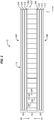
- FIG. 2 is a front view illustrating core 122 and facesheets 124 of composite panel 120 in an exemplary embodiment.
- FIG. 2 corresponds with view arrows 2 of FIG. 1 .
- FIG. 2 illustrates that each facesheet 124 may include one or more layers 220 of composite.
- the layers 220 of composite may comprise, for example, multiple layers of Fiber Reinforced Polymer (FRP), such as fiberglass reinforced polymer or Carbon Fiber Reinforced Polymer (CFRP).
- FRP Fiber Reinforced Polymer
- CFRP Carbon Fiber Reinforced Polymer
- each facesheet 124 further includes a finish layer 210.
- Finish layer 210 may enhance the aesthetic quality of a facesheet 124, and may comprise a Polyvinyl Fluoride (PVF) material such as TEDLAR. Finish layer 210 is not necessary in all applications and may be foregone entirely in some embodiments.
- PVF Polyvinyl Fluoride
- One facesheet 124 covers a top 250 of core 122, and another facesheet 114 covers a bottom 260 of core 122.
- Top 280 and bottom 290 of composite panel 120 are also illustrated.
- FIG. 2 further illustrates core 122, which resists vertical crushing forces (F1) applied to composite panel 120.
- core 122 includes walls 230 (e.g., composite walls), which subdivide core 122 into a grid 232 of cells 240 that extend in-plane. Walls 230 may form a square grid, diamond grid, hexagonal "honeycomb" grid, etc. Because walls 230 extend vertically (along Y), grid 232 resists crushing forces (i.e., along Y) applied to composite panel 120. Meanwhile, bending force resistance is provided by the spacing apart of facesheets 124, and by preventing shear between facesheets 124 and the core 122.
- walls 230 e.g., composite walls
- grid 232 resists crushing forces (i.e., along Y) applied to composite panel 120.
- bending force resistance is provided by the spacing apart of facesheets 124, and by preventing shear between facesheets 124 and the core 122.
- Each cell 240 may be hollow, and may extend from top 250 of core 122 to bottom 260 of core 122.
- Composite panel 110 may exhibit a similar composition to that of composite panel 120.
- core 122 comprises a solid, stiff, and/or rigid open or closed cell foam.
- cells 240 may comprise voids within the foam, and walls 230 may, instead of being vertical, be amorphous in form.
- Core 112 may also or alternatively include foam as desired.
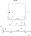
- FIG. 3 is a front view illustrating assembly of the composite panels of FIG. 1 in an exemplary embodiment.
- FIG. 3 illustrates that composite panel 110 includes a first slot 310 having a predetermined depth D1, and that composite panel 120 includes a second slot 320 having a predetermined depth D2.
- slot 310 penetrates only into core 112 of composite panel 110, while slot 320 penetrates through a facesheet 124 as well as into core 122 of composite panel 120.
- depth D2 is equal to the thickness of one facesheet 124, plus the thickness of core 122.
- Depths D1 and D2 need not be equal.
- depth D1 is substantially deeper than D2 (e.g., one and a half to four times as deep, such as twice as deep).
- each blade 330 may correspond with the combined depth of a slot 310 and a slot 320. Further details of slot 310 and slot 320 are provided in FIGS. 4-5 . Note that while slots 310, slot 320 and blade 330 are shown as having rounded corners, they may have square corners in further embodiments.
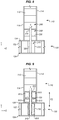
- FIG. 4 is a bottom view of composite panel 110 of FIG. 3 in an exemplary embodiment. Specifically, FIG. 4 corresponds with view arrows 4 of FIG. 3 .
- Slots 310 penetrate through walls 230 and extend into composite panel 110 a depth D1 along Y (see FIG. 1 ). That is, slots 310 penetrate core 112 perpendicular to the walls of core 112 and substantially parallel to facesheets 114. Slots 310 have a length (L) and a thickness (T). T may be smaller than the thickness of core 122 and/or panel 120. Thus, in an embodiment where each composite panel has a thickness of between one quarter of an inch and one inch, T may be between fifty and one hundred and fifty thousandths of an inch. L may be any suitable length.
- slots 310 and slots 320 may be aligned with, staggered, or offset with respect to each other and/or centerline 490 of core 112, such that they each occupy a different position along Z.
- slots 310 and/or slots 320 may be arranged, angled, or located other than parallel to centerline 490 of facesheets 114. It is even possible for slots to be arranged/located on either side of centerline 490 running through core 112 and parallel to facesheets 114.
- slots 310 are further arranged/located to directly border/contact one or more facesheets 114, may be located directly in contact with one or more facesheet 114, and may be in line with facesheet 114.
- FIG. 5 is a top view of composite panel 120 of FIG. 3 in an exemplary embodiment. Specifically, FIG. 5 corresponds with view arrows 5 of FIG. 3 .
- FIG. 5 includes slots 320, which may have the same thickness (T2) and length as slots 310, or a different thickness and length than slots 310. Slots 320 penetrate through a facesheet 124 of panel 120 perpendicular to the facesheet 124, and also at least partially penetrate core 122 (as shown in FIG. 2 ). In embodiments where the dimensions of slots 310 and slots 320 differ, blades 330 may be sized to accommodate these varying dimensions.
- a thickness (e.g., T, T2) of slots 310 and slots 320 may be less thick than a thickness (T3, FIG. 6 ) of blades 330 (in order to facilitate a friction fit), or may be more thick than a thickness of blades 330 (in order to facilitate ease of installation).
- the combined depth (D1 + D2, FIG. 3 ) of a slot 310 and a slot 320 corresponds with a height (H, FIG. 3 ) of an individual blade 330. In this manner, sufficient material is removed to enable the insertion of a blade 330, without removing more material than needed.
- FIG. 6 is a bottom view of blade 330 of FIG. 3 in an exemplary embodiment. Specifically, FIG. 6 corresponds with view arrows 6 of FIG. 3 .
- FIG. 6 illustrates that each blade 330 may comprise one or multiple layers 610 of composite material, depending on a desired thickness of blade 330.
- each blade 330 may be made from the same material as a facesheet 114. The fiber orientations of different layers 610 may vary in order to enhance the strength of blade 330 with respect to forces applied from different directions.
- blades 330 may be made from metal or a rigid plastic. Blade 330 is thinner (i.e., along Z) than composite panel 110 and composite panel 120. Blade 330 may have a thickness corresponding with a thickness of slot 310 and a thickness of slot 320.
- blade 330 includes additional features to enhance its strength, such as ridges or texture that increase contact area with an adhesive.
- FIG. 7 is a cut-through front view of composite panel 110 of FIG. 3 in an exemplary embodiment.
- the locations of cuts forming slots 310 are illustrated with dotted lines 712. Dotted lines 712 in FIG. 7 therefore do not illustrate walls 230, but rather are boundaries indicating the endpoints of cuts that have been made into walls 230 in order to form volume 710. Because the cuts penetrate through a plurality of walls 230 and into cells 240, additional volumes 720 are exposed by the cuts. These additional volumes 720 help to facilitate the penetration of adhesive into slots 310, which in turn enhances the overall strength of bonding between composite panel 110 and composite panel 120. That is, adhesive follows flow pathways indicated by arrows 730 when a blade is inserted into a slot 310 that has already been filled with adhesive.
- FIGS. 8-9 provide cut-through side views of composite panel 110 and composite panel 120 of FIG. 3 being affixed together by a blade 330 in an exemplary embodiment.
- FIGS. 8-9 correspond with view arrows 8 of FIG. 1 .
- FIG. 8 illustrates a "dry fit" alignment of first composite panel 110 with second composite panel 120
- FIG. 9 illustrates composite panel 110 and composite panel 120 being permanently affixed via use of blade 330 and adhesive 910.
- Adhesive 910 enters not just slots 310 and 320, but also any cells 240 that have been cut into by slots 310 and 320. This enhances the overall bond strength between composite panel 110 and composite panel 120.
- Adhesive 910 may for example fill cells 240, touching both blade 330 and cell walls 230. After adhesive 910 has dried, panel 110 is permanently affixed/joined to composite panel 120. Hence, composite panel 110 and composite panel 120 strongly resist pull-out forces F2.
- the bond between composite panel 110 and composite panel 120 is unique in that it utilizes a blade-and-slot geometry in an unexpected arrangement. That is, since slot 310 penetrates perpendicularly into core 112, little material interference initially exists between blade 330 and walls 230 of composite panel 110. However, because adhesive 910 is pushed into cells 240 by the insertion of blade 330, adhesive 910 provides additional structural strength that prevents dis-bonding. In some embodiments, adhesive 910 within a slot may further flow outward along Z into contact with facesheets 114 when blade 330 is inserted. Thus, blade 330 may bond to facesheets 114, even further enhancing joint strength by enabling facesheets 114 to bear pull-out forces F2.
- FIG. 10 Illustrative details of the operation of the blade-and-slot system of FIGS. 1-9 will be discussed with regard to FIG. 10 . Assume, for this embodiment, that a technician wishes to join two composite panels that have complementary slots.
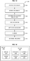
- FIG. 10 is a flowchart illustrating a method 1000 for utilizing a blade-and-slot system in an exemplary embodiment.
- the steps of method 1000 are described with reference to blade-and-slot system 100 of FIG. 1 , but those skilled in the art will appreciate that method 1000 may be performed in other blade-and-slot systems.
- the steps of the flowcharts described herein are not all inclusive and may include other steps not shown. The steps described herein may also be performed in an alternative order.
- Method 1000 may initiate with the acquisition of first composite panel 110, and cutting a first slot 310 into composite panel 110 (step 1002).
- First slot 310 penetrates through walls 230 of composite panel 110.
- Second composite panel 120 is also acquired, and slot 320 is cut into composite panel 120 (step 1004).
- Slot 320 penetrates through facesheet 124 of composite panel 120, as well as penetrating through walls 230 of composite panel 120.
- Composite panel 110 and composite panel 120 may include cores with evenly spaced vertical walls, or may comprise solid foams having amorphous walls as mentioned above.
- core 112 may comprise a solid foam of amorphous walls 230 defining cells 240, or core 112 may include vertical walls 230 that define a grid 232 of cells 240.
- First composite panel 110 further includes a slot 310 that penetrates through grid 232 and/or cells 240.
- slot 310 may penetrate through walls 230 at an angle that is perpendicular to walls 230.
- method 1000 may further comprise cutting slot 310 at panel 110, and cutting slot 320 at panel 120.
- adhesive 910 is applied to slot 310 (step 1006).
- adhesive 910 may be applied until slot 310 is filled with adhesive 910.
- adhesive 910 may be substantially tacky and/or viscous, air pockets may remain within cells 240 adjacent to slot 310, even after slot 310 has been filled with adhesive 910. This may also be referred to as "potting" core 112.
- Blade 330 is inserted into slot 310 (step 1008).
- the action of inserting blade 330 drives adhesive 910 within slot 310 deeper into cells 240 within core 112 of panel 110. That is, adhesive 910 is driven into volumes 710 illustrated in FIG. 7 , which may even cause adhesive 910 to be driven against facesheets 114.
- blades 330 do not contact facesheets 114 when inserted into composite panel 110.
- Adhesive 910 is applied to second slot 320 of second composite panel 120 (step 1010).
- Method 1000 further includes inserting blade 330 into slot 320, thereby driving adhesive 910 within slot 320 into cells within the core of the second composite panel (step 1012). This may further comprise waiting for adhesive 910 to fix blade 330 and the panels together (step 1014). In this manner, composite panel 110 and composite panel 120 are affixed perpendicular to each other after blade 330 has been inserted into slot 310 and slot 320.
- Method 1000 provides a substantial benefit in that it enables composite panels to be affixed cleanly to form joints.
- the slots are advantageously placed in locations which would normally be expected to exhibit mechanical weakness, yet surprisingly overcomes this deficiency by pushing adhesive 910 into empty volumes that have been cut into by slots 310 and 320.
- composite panel 110 and composite panel 120 provide a flow pathway for adhesive 910 that is entirely internal to the panels being united (as indicated by arrows 730), and therefore prevents excess adhesive 910 from flowing out of the panels.
- a portion 1110 of core 112 is extended downward from composite panel 110. This extending portion 1110 of core 112 may be placed into a corresponding slot 320 at composite panel 120. This configuration may further facilitate formation of a joint as desired.
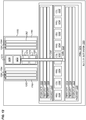
- FIG. 12 is a block diagram of a blade-and-slot system 1200 in an exemplary embodiment.
- panel 1210 and panel 1250 have been bonded together.
- Panel 1210 includes facesheets 1220, which each include one or more plies (fiber reinforced layers) 1224 and a finish layer 1222 (e.g., TEDLAR).
- Core 1230 of panel 1210 includes cells 1232 defined by walls 1234.
- Slot 1240 penetrates through a facesheet 1220 of panel 1210 and through core 1230.
- panel 1250 includes facesheets 1260 which include one or more fiber layers 1264 and a finish layer 1262.
- Core 1270 of panel 1250 includes cells 1272 and walls 1274.
- Slot 1280 penetrates through core 1270.
- Blade 1290 has been inserted into slot 1240 and slot 1280, and beneficially maintains bond strength between panel 1210 and panel 1250.
- core 1230 may comprise a foam as discussed above.
- exemplary method 1300 may include specification and design 1304 of the aircraft 1302 and material procurement 1306.
- component and subassembly manufacturing 1308 and system integration 1310 of the aircraft 1302 takes place.
- the aircraft 1302 may go through certification and delivery 1312 in order to be placed in service 1314.
- routine maintenance and service 1316 which may also include modification, reconfiguration, refurbishment, and so on).
- Apparatus and methods embodied herein may be employed during any one or more suitable stages of the production and service method 1300 (e.g., specification and design 1304, material procurement 1306, component and subassembly manufacturing 1308, system integration 1310, certification and delivery 1312, service 1314, maintenance and service 1316) and/or any suitable component of aircraft 1302 (e.g., airframe 1318, systems 1320, interior 1322, propulsion 1324, electrical 1326, hydraulic 1328, environmental 1330).
- any suitable component of aircraft 1302 e.g., airframe 1318, systems 1320, interior 1322, propulsion 1324, electrical 1326, hydraulic 1328, environmental 1330.
- a system integrator may include without limitation any number of aircraft manufacturers and major-system subcontractors; a third party may include without limitation any number of vendors, subcontractors, and suppliers; and an operator may be an airline, leasing company, military entity, service organization, and so on.
- the aircraft 1302 produced by exemplary method 1300 may include an airframe 1318 with a plurality of systems 1320 and an interior 1322.
- high-level systems 1320 include one or more of a propulsion system 1324, an electrical system 1326, a hydraulic system 1328, and an environmental system 1330. Any number of other systems may be included.
- an aerospace example is shown, the principles of the invention may be applied to other industries, such as the automotive industry.
- apparatus and methods embodied herein may be employed during any one or more of the stages of the production and service method 1300.
- components or subassemblies corresponding to production stage 1308 may be fabricated or manufactured in a manner similar to components or subassemblies produced while the aircraft 1302 is in service.
- one or more apparatus embodiments, method embodiments, or a combination thereof may be utilized during the production stages 1308 and 1310, for example, by substantially expediting assembly of or reducing the cost of an aircraft 1302.
- apparatus embodiments, method embodiments, or a combination thereof may be utilized while the aircraft 1302 is in service, for example and without limitation, to maintenance and service 1316.
- the techniques and systems described herein may be used for steps 1306, 1308, 1310, 1314, and/or 1316, and/or may be used for airframe 1318 and/or interior 1322. These techniques and systems may even be utilized for systems 1320, including for example propulsion 1324, electrical 1326, hydraulic 1328, and/or environmental 1330.
- panels 110 and 120 comprise a portion of interior 1322, and are manufactured during component and subassembly manufacturing 1308.
- the panels may then be assembled via blade-and-slot system 100 into an aircraft in system integration 1310, and then be utilized in service 1314 until wear renders the composite panels unusable. Then, in maintenance and service 1316, the composite panels may be discarded and replaced with newly manufactured panels. Blade-and-slot techniques may be utilized throughout component and subassembly manufacturing 1308 in order to assemble the new panels.
Landscapes
- Engineering & Computer Science (AREA)
- Mechanical Engineering (AREA)
- General Engineering & Computer Science (AREA)
- Aviation & Aerospace Engineering (AREA)
- Manufacturing & Machinery (AREA)
- Transportation (AREA)
- Laminated Bodies (AREA)
- Perforating, Stamping-Out Or Severing By Means Other Than Cutting (AREA)
Abstract
Description
- The disclosure relates to the field of composite materials, and in particular, to joining composite panels.
- Composite materials (e.g., carbon fiber, fiberglass, etc.) are used to fabricate a variety of mechanical components. When creating a particularly complex component, it may be beneficial to assemble the component from multiple composite panels. However, it remains a complicated process to unite composite panels with the desired structural strength. This is particularly true with regards to composite panels that utilize a core. In an aerospace environment, it may also be particularly desirable to utilize smaller amounts of adhesive when forming a joint. Using less adhesive to form a joint beneficially reduces the weight of that joint, which improves fuel efficiency of a corresponding aircraft.
- Thus, those of ordinary skill in the art continue to seek out enhancements to the techniques by which composite panels are joined.
- Embodiments described herein provide for blade-and-slot systems in which slots are cut into a partially hollow core of a composite panel. The slots may extend perpendicular to a direction of walls within the core of the composite panel. A blade may be inserted and glued into a slot at a face/end of each of two different panels. The bonding process may for example be performed as a single event with the blade placed in both panels before an adhesive is cured. The blades are internal and hence are not visible after installation. These systems for blade-and-slot joining of panels exhibit high levels of mechanical strength, and enable composite panels to be joined together in a straightforward manner that also does not spill adhesive onto the exterior of the composite panels which are being united. That is, the blade-and-slot systems described herein enhance ease of assembly, result in a minimal amount of adhesive clean up, and add minimal weight. Hence, joints between the panels remain aesthetically pleasing, strong, and fire resistant, which is highly beneficial for aircraft interiors.
- One embodiment is a method that includes cutting a first slot into a first composite panel that includes a core between two facesheets. The first slot penetrates through the core of the first composite panel. The method also includes cutting a second slot into a second composite panel that includes a core between two facesheets. The second slot penetrates through a facesheet of the second composite panel as well as the core of the second composite panel. The method further includes inserting a blade into the first slot, and inserting the blade into the second slot.
- A further embodiment is an apparatus that includes a first composite panel and a second composite panel. Each composite panel comprises a first facesheet that extends laterally across a top of the panel, a second facesheet that extends laterally across a bottom of the panel, and a core that separates the first facesheet and the second facesheet. The apparatus also includes a blade that occupies a first slot that penetrates laterally through the core of the first composite panel between the facesheets of the first composite panel. The blade further occupies a second slot that penetrates vertically through the first facesheet of the second composite panel into the core of the second composite panel. The apparatus also includes adhesive that secures the blade into the first slot and the second slot.
- A further embodiment is a system. The system includes a first composite panel and a second composite panel. A first facesheet extends laterally across a top of the panel. A second facesheet extends laterally across a bottom of the panel. A core separates the first facesheet and the second facesheet. A first slot penetrates laterally through cells of the core of the first composite panel between the facesheets of the first composite panel, has a thickness less than a thickness of the first composite panel, and extends a predetermined depth into the first composite panel. A second slot penetrates vertically through the first facesheet and the core of the second composite panel into cells of the second composite panel, and extends a predetermined depth into the composite panel. A blade is dimensioned for insertion into the first slot and the second slot.
- A further embodiment is an apparatus. The apparatus includes a first composite panel. The first composite panel includes a first facesheet that extends laterally across a top of the first composite panel, a second facesheet that extends laterally across a bottom of the first composite panel, and a first core separating the first facesheet and the second facesheet. A portion of the first core extends beyond the first facesheet and the second facesheet at an end of the first composite panel, and extends a predetermined depth beyond the end of the panel. A second composite panel includes a third facesheet that extends laterally across a top of the second composite panel, a fourth facesheet that extends laterally across a bottom of the second composite panel, and a second core separating the third facesheet and the fourth facesheet. A slot penetrates through the third facesheet as well as penetrating through the second core. The portion of the first core is inserted into the slot and affixed to the slot via adhesive.
- Other exemplary embodiments (e.g., methods and computer-readable media relating to the foregoing embodiments) may be described below. The features, functions, and advantages that have been discussed can be achieved independently in various embodiments or may be combined in yet other embodiments further details of which can be seen with reference to the following description and drawings.
- Some embodiments of the present disclosure are now described, by way of example only, and with reference to the accompanying drawings. The same reference number represents the same element or the same type of element on all drawings.
-
FIG. 1 is a perspective view of two composite panels that have been joined via a blade-and-slot system in an exemplary embodiment. -
FIG. 2 is a front view illustrating a core and facesheets of a composite panel in an exemplary embodiment. -
FIG. 3 is a front view illustrating assembly of the composite panels ofFIG. 1 in an exemplary embodiment. -
FIG. 4 is a bottom view of a first composite panel ofFIG. 3 in an exemplary embodiment. -
FIG. 5 is a top view of a second composite panel ofFIG. 3 in an exemplary embodiment. -
FIG. 6 is a bottom view of an insertable blade ofFIG. 3 in an exemplary embodiment. -
FIG. 7 is a cut-through front view of the first composite panel ofFIG. 3 in an exemplary embodiment. -
FIGS. 8-9 are cut-through side views of the first composite panel and second composite panel ofFIG. 3 being affixed together by a blade in an exemplary embodiment. -
FIG. 10 is a flowchart illustrating a method of utilizing a blade-and-slot system in an exemplary embodiment. -
FIG. 11 is a diagram illustrating a further blade-and-slot system in an exemplary embodiment. -
FIG. 12 is a block diagram of a blade-and-slot system in an exemplary embodiment. -
FIG. 13 is a flow diagram of aircraft production and service methodology in an exemplary embodiment. -
FIG. 14 is a block diagram of an aircraft in an exemplary embodiment. - The figures and the following description illustrate specific exemplary embodiments of the disclosure. It will thus be appreciated that those skilled in the art will be able to devise various arrangements that, although not explicitly described or shown herein, embody the principles of the disclosure and are included within the scope of the disclosure. Furthermore, any examples described herein are intended to aid in understanding the principles of the disclosure, and are to be construed as being without limitation to such specifically recited examples and conditions. As a result, the disclosure is not limited to the specific embodiments or examples described below, but by the claims and their equivalents.
-
FIG. 1 is a perspective view diagram of two composite panels (110, 120) that have been joined via a blade-and-slot system 100 in an exemplary embodiment. Composite materials may may comprise, for example, multiple layers of Fiber Reinforced Polymer (FRP), such as fiberglass reinforced polymer or Carbon Fiber Reinforced Polymer (CFRP), and composite panels may comprise panels made of such composite materials.FIG. 1 depicts firstcomposite panel 110, which includescore 112 andfacesheets 114.Surface 116 offacesheet 114 is also illustrated, as isend 118 which contacts secondcomposite panel 120. Secondcomposite panel 120 includescore 122 andfacesheets 124. The facesheets (114, 124) extend (e.g., laterally across a top (or bottom) of) their corresponding core (112, 122), and resist in-plane forces applied to their corresponding composite panel (110, 120). Firstcomposite panel 110 is joined to secondcomposite panel 120. In this arrangement, end 118 of firstcomposite panel 110 contacts surface 126 offacesheet 124 of secondcomposite panel 120. -
FIGS. 2-7 illustrate further details of the various components utilized for blade-and-slot system 100. For example,FIG. 2 is a frontview illustrating core 122 andfacesheets 124 ofcomposite panel 120 in an exemplary embodiment.FIG. 2 corresponds withview arrows 2 ofFIG. 1 .FIG. 2 illustrates that each facesheet 124 may include one ormore layers 220 of composite. Note thatFIG. 2 is not drawn to scale and is drawn in a slightly exploded view. Thelayers 220 of composite may comprise, for example, multiple layers of Fiber Reinforced Polymer (FRP), such as fiberglass reinforced polymer or Carbon Fiber Reinforced Polymer (CFRP). Eachlayer 220 may exhibit strands of fiber that are oriented parallel with each other and in-plane withinlayer 220. Furthermore, different layers may exhibit different fiber orientations. This substantially increases the strength of each facesheet with respect to lateral forces that are applied in-plane alongsurface 126. In this embodiment, eachfacesheet 124 further includes afinish layer 210.Finish layer 210 may enhance the aesthetic quality of afacesheet 124, and may comprise a Polyvinyl Fluoride (PVF) material such as TEDLAR.Finish layer 210 is not necessary in all applications and may be foregone entirely in some embodiments. Onefacesheet 124 covers a top 250 ofcore 122, and anotherfacesheet 114 covers abottom 260 ofcore 122. Top 280 andbottom 290 ofcomposite panel 120 are also illustrated. -
FIG. 2 further illustratescore 122, which resists vertical crushing forces (F1) applied tocomposite panel 120. In this embodiment,core 122 includes walls 230 (e.g., composite walls), which subdividecore 122 into agrid 232 ofcells 240 that extend in-plane.Walls 230 may form a square grid, diamond grid, hexagonal "honeycomb" grid, etc. Becausewalls 230 extend vertically (along Y),grid 232 resists crushing forces (i.e., along Y) applied tocomposite panel 120. Meanwhile, bending force resistance is provided by the spacing apart offacesheets 124, and by preventing shear betweenfacesheets 124 and thecore 122. Eachcell 240 may be hollow, and may extend fromtop 250 ofcore 122 tobottom 260 ofcore 122.Composite panel 110 may exhibit a similar composition to that ofcomposite panel 120. Infurther embodiments core 122 comprises a solid, stiff, and/or rigid open or closed cell foam. In such embodiments,cells 240 may comprise voids within the foam, andwalls 230 may, instead of being vertical, be amorphous in form.Core 112 may also or alternatively include foam as desired. -
FIG. 3 is a front view illustrating assembly of the composite panels ofFIG. 1 in an exemplary embodiment.FIG. 3 illustrates thatcomposite panel 110 includes afirst slot 310 having a predetermined depth D1, and thatcomposite panel 120 includes asecond slot 320 having a predetermined depth D2. In this embodiment,slot 310 penetrates only intocore 112 ofcomposite panel 110, whileslot 320 penetrates through afacesheet 124 as well as intocore 122 ofcomposite panel 120. In one embodiment, depth D2 is equal to the thickness of onefacesheet 124, plus the thickness ofcore 122. Depths D1 and D2 need not be equal. In some embodiments, depth D1 is substantially deeper than D2 (e.g., one and a half to four times as deep, such as twice as deep). This increases the amount of structural strength whenpanel 110 andpanel 120 are joined. That is, when an insertable blade 330 (also referred to as a "blade") penetrates deeper into a slot, there is more material atblade 330 which will be bound to the core (112, 122), which increases the mechanical strength of the resulting joint.Blades 330 are inserted intoslots blade 330 may correspond with the combined depth of aslot 310 and aslot 320. Further details ofslot 310 and slot 320 are provided inFIGS. 4-5 . Note that whileslots 310,slot 320 andblade 330 are shown as having rounded corners, they may have square corners in further embodiments. -
FIG. 4 is a bottom view ofcomposite panel 110 ofFIG. 3 in an exemplary embodiment. Specifically,FIG. 4 corresponds withview arrows 4 ofFIG. 3 .Slots 310 penetrate throughwalls 230 and extend into composite panel 110 a depth D1 along Y (seeFIG. 1 ). That is,slots 310 penetratecore 112 perpendicular to the walls ofcore 112 and substantially parallel to facesheets 114.Slots 310 have a length (L) and a thickness (T). T may be smaller than the thickness ofcore 122 and/orpanel 120. Thus, in an embodiment where each composite panel has a thickness of between one quarter of an inch and one inch, T may be between fifty and one hundred and fifty thousandths of an inch. L may be any suitable length. In further embodiments,slots 310 andslots 320 may be aligned with, staggered, or offset with respect to each other and/orcenterline 490 ofcore 112, such that they each occupy a different position along Z. In other embodiments,slots 310 and/orslots 320 may be arranged, angled, or located other than parallel to centerline 490 offacesheets 114. It is even possible for slots to be arranged/located on either side ofcenterline 490 running throughcore 112 and parallel to facesheets 114. In someembodiments slots 310 are further arranged/located to directly border/contact one or more facesheets 114, may be located directly in contact with one ormore facesheet 114, and may be in line withfacesheet 114. -
FIG. 5 is a top view ofcomposite panel 120 ofFIG. 3 in an exemplary embodiment. Specifically,FIG. 5 corresponds withview arrows 5 ofFIG. 3 .FIG. 5 includesslots 320, which may have the same thickness (T2) and length asslots 310, or a different thickness and length thanslots 310.Slots 320 penetrate through afacesheet 124 ofpanel 120 perpendicular to thefacesheet 124, and also at least partially penetrate core 122 (as shown inFIG. 2 ). In embodiments where the dimensions ofslots 310 andslots 320 differ,blades 330 may be sized to accommodate these varying dimensions. - A thickness (e.g., T, T2) of
slots 310 andslots 320 may be less thick than a thickness (T3,FIG. 6 ) of blades 330 (in order to facilitate a friction fit), or may be more thick than a thickness of blades 330 (in order to facilitate ease of installation). - In some embodiments, the combined depth (D1 + D2,
FIG. 3 ) of aslot 310 and aslot 320 corresponds with a height (H,FIG. 3 ) of anindividual blade 330. In this manner, sufficient material is removed to enable the insertion of ablade 330, without removing more material than needed. -
FIG. 6 is a bottom view ofblade 330 ofFIG. 3 in an exemplary embodiment. Specifically,FIG. 6 corresponds withview arrows 6 ofFIG. 3 .FIG. 6 illustrates that eachblade 330 may comprise one ormultiple layers 610 of composite material, depending on a desired thickness ofblade 330. For example, eachblade 330 may be made from the same material as afacesheet 114. The fiber orientations ofdifferent layers 610 may vary in order to enhance the strength ofblade 330 with respect to forces applied from different directions. In further embodiments,blades 330 may be made from metal or a rigid plastic.Blade 330 is thinner (i.e., along Z) thancomposite panel 110 andcomposite panel 120.Blade 330 may have a thickness corresponding with a thickness ofslot 310 and a thickness ofslot 320. In further embodiments,blade 330 includes additional features to enhance its strength, such as ridges or texture that increase contact area with an adhesive. - With basic illustrations of the components of a blade-and-slot system described above, further details are now provided of how
composite panel 110 and secondcomposite panel 120 may be joined. -
FIG. 7 is a cut-through front view ofcomposite panel 110 ofFIG. 3 in an exemplary embodiment. In this embodiment, the locations ofcuts forming slots 310 are illustrated withdotted lines 712.Dotted lines 712 inFIG. 7 therefore do not illustratewalls 230, but rather are boundaries indicating the endpoints of cuts that have been made intowalls 230 in order to formvolume 710. Because the cuts penetrate through a plurality ofwalls 230 and intocells 240,additional volumes 720 are exposed by the cuts. Theseadditional volumes 720 help to facilitate the penetration of adhesive intoslots 310, which in turn enhances the overall strength of bonding betweencomposite panel 110 andcomposite panel 120. That is, adhesive follows flow pathways indicated byarrows 730 when a blade is inserted into aslot 310 that has already been filled with adhesive. - With a description of various slots, blades, and composite panels provided above,
FIGS. 8-9 provide cut-through side views ofcomposite panel 110 andcomposite panel 120 ofFIG. 3 being affixed together by ablade 330 in an exemplary embodiment.FIGS. 8-9 correspond withview arrows 8 ofFIG. 1 . Specifically,FIG. 8 illustrates a "dry fit" alignment of firstcomposite panel 110 with secondcomposite panel 120, whileFIG. 9 illustratescomposite panel 110 andcomposite panel 120 being permanently affixed via use ofblade 330 and adhesive 910.Adhesive 910 enters not justslots cells 240 that have been cut into byslots composite panel 110 andcomposite panel 120. Adhesive 910 may for example fillcells 240, touching bothblade 330 andcell walls 230. After adhesive 910 has dried,panel 110 is permanently affixed/joined tocomposite panel 120. Hence,composite panel 110 andcomposite panel 120 strongly resist pull-out forces F2. - The bond between
composite panel 110 andcomposite panel 120 is unique in that it utilizes a blade-and-slot geometry in an unexpected arrangement. That is, sinceslot 310 penetrates perpendicularly intocore 112, little material interference initially exists betweenblade 330 andwalls 230 ofcomposite panel 110. However, becauseadhesive 910 is pushed intocells 240 by the insertion ofblade 330, adhesive 910 provides additional structural strength that prevents dis-bonding. In some embodiments, adhesive 910 within a slot may further flow outward along Z into contact withfacesheets 114 whenblade 330 is inserted. Thus,blade 330 may bond to facesheets 114, even further enhancing joint strength by enablingfacesheets 114 to bear pull-out forces F2. - Illustrative details of the operation of the blade-and-slot system of
FIGS. 1-9 will be discussed with regard toFIG. 10 . Assume, for this embodiment, that a technician wishes to join two composite panels that have complementary slots. -
FIG. 10 is a flowchart illustrating amethod 1000 for utilizing a blade-and-slot system in an exemplary embodiment. The steps ofmethod 1000 are described with reference to blade-and-slot system 100 ofFIG. 1 , but those skilled in the art will appreciate thatmethod 1000 may be performed in other blade-and-slot systems. The steps of the flowcharts described herein are not all inclusive and may include other steps not shown. The steps described herein may also be performed in an alternative order. -
Method 1000 may initiate with the acquisition of firstcomposite panel 110, and cutting afirst slot 310 into composite panel 110 (step 1002).First slot 310 penetrates throughwalls 230 ofcomposite panel 110. Secondcomposite panel 120 is also acquired, andslot 320 is cut into composite panel 120 (step 1004).Slot 320 penetrates throughfacesheet 124 ofcomposite panel 120, as well as penetrating throughwalls 230 ofcomposite panel 120.Composite panel 110 andcomposite panel 120 may include cores with evenly spaced vertical walls, or may comprise solid foams having amorphous walls as mentioned above. For example,core 112 may comprise a solid foam ofamorphous walls 230 definingcells 240, orcore 112 may includevertical walls 230 that define agrid 232 ofcells 240. That is,walls 230 may subdividecore 112 intogrid 232. Firstcomposite panel 110 further includes aslot 310 that penetrates throughgrid 232 and/orcells 240. For example, slot 310 may penetrate throughwalls 230 at an angle that is perpendicular towalls 230. In some embodiments,method 1000 may further comprise cuttingslot 310 atpanel 110, and cuttingslot 320 atpanel 120. - With the panels acquired, adhesive 910 is applied to slot 310 (step 1006). For example, adhesive 910 may be applied until
slot 310 is filled withadhesive 910. Because adhesive 910 may be substantially tacky and/or viscous, air pockets may remain withincells 240 adjacent to slot 310, even afterslot 310 has been filled withadhesive 910. This may also be referred to as "potting"core 112. -
Blade 330 is inserted into slot 310 (step 1008). The action of insertingblade 330 drives adhesive 910 withinslot 310 deeper intocells 240 withincore 112 ofpanel 110. That is, adhesive 910 is driven intovolumes 710 illustrated inFIG. 7 , which may even cause adhesive 910 to be driven againstfacesheets 114. Depending on the thickness ofblades 330, in someembodiments blades 330 do not contactfacesheets 114 when inserted intocomposite panel 110. -
Adhesive 910 is applied tosecond slot 320 of second composite panel 120 (step 1010).Method 1000 further includes insertingblade 330 intoslot 320, thereby driving adhesive 910 withinslot 320 into cells within the core of the second composite panel (step 1012). This may further comprise waiting for adhesive 910 to fixblade 330 and the panels together (step 1014). In this manner,composite panel 110 andcomposite panel 120 are affixed perpendicular to each other afterblade 330 has been inserted intoslot 310 andslot 320. -
Method 1000 provides a substantial benefit in that it enables composite panels to be affixed cleanly to form joints. The slots are advantageously placed in locations which would normally be expected to exhibit mechanical weakness, yet surprisingly overcomes this deficiency by pushing adhesive 910 into empty volumes that have been cut into byslots composite panel 110 andcomposite panel 120 provide a flow pathway for adhesive 910 that is entirely internal to the panels being united (as indicated by arrows 730), and therefore prevents excess adhesive 910 from flowing out of the panels. However, in some embodiments it may be desirable for insertion ofblade 330 into aslot 310 to cause excess adhesive 910 to flow out (i.e., "squeeze out") ofslot 310, which may be indicative of having a sufficient amount of adhesive 910 in the joint. In environments where aflammable adhesive 910 is utilized, this is highly advantageous because it reduces the flammability of the resulting joint. - In even further embodiments as illustrated in
FIG. 11 , aportion 1110 ofcore 112 is extended downward fromcomposite panel 110. This extendingportion 1110 ofcore 112 may be placed into acorresponding slot 320 atcomposite panel 120. This configuration may further facilitate formation of a joint as desired. - In the following examples, additional processes, systems, and methods are described in the context of a blade-and-slot system for bonding composite panels.
-
FIG. 12 is a block diagram of a blade-and-slot system 1200 in an exemplary embodiment. As shown inFIG. 12 ,panel 1210 andpanel 1250 have been bonded together.Panel 1210 includes facesheets 1220, which each include one or more plies (fiber reinforced layers) 1224 and a finish layer 1222 (e.g., TEDLAR).Core 1230 ofpanel 1210 includescells 1232 defined bywalls 1234.Slot 1240 penetrates through a facesheet 1220 ofpanel 1210 and throughcore 1230. Meanwhile,panel 1250 includes facesheets 1260 which include one ormore fiber layers 1264 and afinish layer 1262.Core 1270 ofpanel 1250 includescells 1272 andwalls 1274.Slot 1280 penetrates throughcore 1270.Blade 1290 has been inserted intoslot 1240 andslot 1280, and beneficially maintains bond strength betweenpanel 1210 andpanel 1250. In further embodiments,core 1230 may comprise a foam as discussed above. - Referring more particularly to the drawings, embodiments of the disclosure may be described in the context of an aircraft manufacturing and
service method 1300 as shown inFIG. 13 and anaircraft 1302 as shown inFIG. 14 . During pre-production,exemplary method 1300 may include specification anddesign 1304 of theaircraft 1302 andmaterial procurement 1306. During production, component andsubassembly manufacturing 1308 andsystem integration 1310 of theaircraft 1302 takes place. Thereafter, theaircraft 1302 may go through certification anddelivery 1312 in order to be placed inservice 1314. While in service by a customer, theaircraft 1302 is scheduled for routine maintenance and service 1316 (which may also include modification, reconfiguration, refurbishment, and so on). Apparatus and methods embodied herein may be employed during any one or more suitable stages of the production and service method 1300 (e.g., specification anddesign 1304,material procurement 1306, component andsubassembly manufacturing 1308,system integration 1310, certification anddelivery 1312,service 1314, maintenance and service 1316) and/or any suitable component of aircraft 1302 (e.g.,airframe 1318,systems 1320, interior 1322,propulsion 1324, electrical 1326, hydraulic 1328, environmental 1330). - Each of the processes of
method 1300 may be performed or carried out by a system integrator, a third party, and/or an operator (e.g., a customer). For the purposes of this description, a system integrator may include without limitation any number of aircraft manufacturers and major-system subcontractors; a third party may include without limitation any number of vendors, subcontractors, and suppliers; and an operator may be an airline, leasing company, military entity, service organization, and so on. - As shown in
FIG. 14 , theaircraft 1302 produced byexemplary method 1300 may include anairframe 1318 with a plurality ofsystems 1320 and an interior 1322. Examples of high-level systems 1320 include one or more of apropulsion system 1324, anelectrical system 1326, ahydraulic system 1328, and anenvironmental system 1330. Any number of other systems may be included. Although an aerospace example is shown, the principles of the invention may be applied to other industries, such as the automotive industry. - As already mentioned above, apparatus and methods embodied herein may be employed during any one or more of the stages of the production and
service method 1300. For example, components or subassemblies corresponding toproduction stage 1308 may be fabricated or manufactured in a manner similar to components or subassemblies produced while theaircraft 1302 is in service. Also, one or more apparatus embodiments, method embodiments, or a combination thereof may be utilized during theproduction stages aircraft 1302. Similarly, one or more of apparatus embodiments, method embodiments, or a combination thereof may be utilized while theaircraft 1302 is in service, for example and without limitation, to maintenance andservice 1316. For example, the techniques and systems described herein may be used forsteps airframe 1318 and/or interior 1322. These techniques and systems may even be utilized forsystems 1320, including forexample propulsion 1324, electrical 1326, hydraulic 1328, and/or environmental 1330. - In one embodiment,
panels subassembly manufacturing 1308. The panels may then be assembled via blade-and-slot system 100 into an aircraft insystem integration 1310, and then be utilized inservice 1314 until wear renders the composite panels unusable. Then, in maintenance andservice 1316, the composite panels may be discarded and replaced with newly manufactured panels. Blade-and-slot techniques may be utilized throughout component andsubassembly manufacturing 1308 in order to assemble the new panels. - The present invention is also referred to in the following clauses which are not to be confused with the claims.
- A1. A method comprising: cutting a first slot into a first composite panel that includes a core between two facesheets, the first slot penetrating through the core of the first composite panel (1002); cutting a second slot into a second composite panel that includes a core between two facesheets, the second slot penetrating through a facesheet of the second composite panel as well as the core of the second composite panel (1004); inserting a blade into the first slot (1008); and inserting the blade into the second slot (1012).
- A2. The method of clause A1 further comprising: driving adhesive into cells within the core of the first composite panel (1006); and driving adhesive into cells within the core of the second composite panel (1010).
- A3. The method of clause A1 or A2 further comprising: applying adhesive into the first slot by filling the first slot with adhesive.
- A4. The method of any of clauses A1 to A3 wherein: inserting the blade into the first slot causes adhesive to squeeze out of the first slot.
- A5. The method of any of clauses A1 to A4 further comprising: locating the first slot at a centerline of the core of the first composite panel.
- A6. The method of any of clauses A1 to A5 further comprising: locating the first slot offset from a centerline of the core of the first composite panel.
- A7. The method of any of clauses A1 to A6 further comprising: locating the first slot adjacent to a facesheet of the first composite panel.
- A8. The method of any of clauses A1 to A7 further comprising: locating the first slot angled with respect to a centerline of the core of the first composite panel.
- A9. The method of any of clauses A1 to A8 further comprising: locating the first slot in line with a facesheet of the first composite panel.
- A10. The method of any of clauses A1 to A9 further comprising: arranging the first panel and the second panel perpendicular to each other prior to inserting the blade into the first slot and the second slot.
- A11. The method of paragraph any of clauses A1 to A10 further comprising: applying adhesive into the first slot (1006); and applying adhesive into the second slot (1012).
- B1. An apparatus comprising: a first composite panel (110) and a second composite panel (120), each comprising: a first facesheet (114) that extends laterally across a top of the panel; a second facesheet (114) that extends laterally across a bottom of the panel; and a core (112) that separates the first facesheet and the second facesheet; a
blade 330 that occupies afirst slot 310 that penetrates laterally through the core of the first composite panel between the facesheets of the first composite panel; the blade further occupies asecond slot 320 that penetrates vertically through the first facesheet of the second composite panel into the core of the second composite panel; and adhesive (910) that secures the blade into the first slot and the second slot. - B2. The apparatus of clause B1 wherein: each core comprises walls (230) that define a grid (232) of cells (240).
- B3. The apparatus of clause B1 or B2 wherein: the first slot is offset from a centerline (490) of the core of the first composite panel.
- B4. The apparatus of any of clauses B1 to B3 wherein: the first slot contacts at least one of the facesheets of the first composite panel.
- B5. The apparatus of any of clauses B1 to B4 wherein: the first slot is at an angle from a centerline (490) of the core of the first composite panel.
- B6. The apparatus of any of clauses B1 to B5 wherein: at least one of the cores comprises a foam.
- B7. The apparatus of any of clauses B1 to B6 wherein: the first slot is aligned with a centerline of the first composite panel.
- B8. The apparatus of any of clauses B1 to B7 wherein: the first slot and second slot have a combined depth (D1, D2) at least equal to a height (H) of the blade.
- B9. The apparatus of any of clauses B1 to B8 wherein: the first slot has a thickness (T) less than a thickness (T3) of the blade.
- B10. The apparatus of any of clauses B1 to B9 wherein: the first slot has a thickness (T) greater than a thickness (T3) of the blade.
- B11. The apparatus of any of clauses B1 to B10 wherein: the first slot, second slot, and blade have square corners.
- B12. The apparatus of any of clauses B1 to B11 wherein: the first slot, second slot, and blade have round corners.
- B13. The apparatus of any of clauses B1 to B12 wherein: the first slot is in line with a facesheet (114) of the first composite panel.
- C1. A system comprising: a first composite panel (110) and a second composite panel (120), each comprising: a first facesheet (114) that extends laterally across a top of the panel; a second facesheet (114) that extends laterally across a bottom of the panel; and a core (112) that separates the first facesheet and the second facesheet; a first slot (310) that penetrates laterally through cells (240) of the core of the first composite panel between the facesheets of the first composite panel, that has a thickness (T) less than a thickness of the first composite panel, and that extends a predetermined depth (D1) into the first composite panel; a second slot (320) that penetrates vertically through the first facesheet and the core of the second composite panel into cells (240) of the second composite panel, and that extends a predetermined depth (D2) into the composite panel; and a blade (330) dimensioned for insertion into the first slot and the second slot.
- C2. The system of clause C1 further comprising: adhesive (910) inserted into the first slot that occupies cells that have been penetrated by the first slot; and adhesive (910) inserted into the second slot that occupies cells that have been penetrated by the second slot.
- C3. The system of clause C1 or C2 wherein: the blade is inserted in the first slot and inserted in the second slot, thereby affixing the first composite panel and the second composite panel.
- C4. The system of any of clauses C1 to C3 wherein: the core comprises walls (230) that define a grid (232) of cells (240).
- C5. The system of any of clauses C1 to C4 wherein: the first slot is offset from a centerline (490) of the core of the first composite panel.
- C6. The system of any of clauses C1 to C5 wherein: the first slot contacts at least one of the facesheets of the first composite panel.
- C7. The system of any of clauses C1 to C6 wherein: the first slot is at an angle from a centerline of the core of the first composite panel.
- C8. The system of any of clauses C1 to C7 wherein: at least one of the cores comprises a foam.
- C9. The system of any of clauses C1 to C8 wherein: the first slot is aligned with a centerline (490) of the first composite panel.
- C10. The system of any of clauses C1 to C9 wherein: the first slot and second slot have a combined depth (D1, D2) at least equal to a height (H) of the blade.
- C11. The system of any of clauses C1 to C10 wherein: the first slot has a thickness (T) less than a thickness (T3) of the blade.
- C12. The system of any of clauses C1 to C11 wherein: the first slot has a thickness (T) greater than a thickness (T3) of the blade.
- C13. The system of any of clauses C1 to C12 wherein: the first slot, second slot, and blade have square corners.
- C14. The system of any of clauses C1 to C13 wherein: the first slot, second slot, and blade have round corners.
- C15. The system of any of clauses C1 to C14 wherein: the first slot is in line with a facesheet (114) of the first composite panel.
- D1. An apparatus comprising: a first composite panel (110) comprising: a first facesheet (114) that extends laterally across a top of the first composite panel; a second facesheet (114) that extends laterally across a bottom of the first composite panel; a first core (112) separating the first facesheet and the second facesheet; and a portion of the first core that extends beyond the first facesheet and the second facesheet at an end of the first composite panel, and extends a predetermined depth beyond the end of the panel; and a second composite panel comprising: a third facesheet (124) that extends laterally across a top of the second composite panel; a fourth facesheet (124) that extends laterally across a bottom of the second composite panel; a second core (122) separating the third facesheet and the fourth facesheet; and a slot (320) penetrating through the third facesheet as well as penetrating through the second core, the portion of the first core is inserted into the slot and affixed to the slot via adhesive (910).
- D2. The apparatus of clause D1 wherein: the first core comprises a solid foam.
- D3. The apparatus of clause D1 or D2 wherein: the first core comprises walls (230) defining a grid (232) of cells (240).
- D4. The apparatus of clause D3 wherein: the cells are hollow.
- Although specific embodiments are described herein, the scope of the disclosure is not limited to those specific embodiments. The scope of the disclosure is defined by the following claims and any equivalents thereof.
Claims (15)
- A method comprising:cutting a first slot into a first composite panel that includes a core between two facesheets, the first slot penetrating through the core of the first composite panel (1002);cutting a second slot into a second composite panel that includes a core between two facesheets, the second slot penetrating through a facesheet of the second composite panel as well as the core of the second composite panel (1004);inserting a blade into the first slot (1008); andinserting the blade into the second slot (1012).
- The method of claim 1 further comprising:driving adhesive into cells within the core of the first composite panel (1006); anddriving adhesive into cells within the core of the second composite panel (1010).
- The method of claim 1 or 2 further comprising:
applying adhesive into the first slot by filling the first slot with adhesive. - The method of any preceding claim wherein:
inserting the blade into the first slot causes adhesive to squeeze out of the first slot. - The method of any preceding claim further comprising:
locating the first slot at a centerline of the core of the first composite panel. - The method of any preceding further comprising:
locating the first slot offset from a centerline of the core of the first composite panel. - The method of any preceding claim further comprising:
locating the first slot adjacent to a facesheet of the first composite panel. - The method of any preceding claim further comprising:
locating the first slot angled with respect to a centerline of the core of the first composite panel. - The method of any preceding claim further comprising:
locating the first slot in line with a facesheet of the first composite panel. - The method of any preceding claim further comprising:
arranging the first panel and the second panel perpendicular to each other prior to inserting the blade into the first slot and the second slot. - The method of any preceding claim further comprising:applying adhesive into the first slot (1006); andapplying adhesive into the second slot (1012).
- An apparatus comprising:a first composite panel (110) and a second composite panel (120), each comprising:a first facesheet (114) that extends laterally across a top of the panel;a second facesheet (114) that extends laterally across a bottom of the panel; anda core (112) that separates the first facesheet and the second facesheet;a blade 330 that occupies a first slot 310 that penetrates laterally through the core of the first composite panel between the facesheets of the first composite panel;the blade further occupies a second slot 320 that penetrates vertically through the first facesheet of the second composite panel into the core of the second composite panel; andadhesive (910) that secures the blade into the first slot and the second slot.
- The apparatus of claim 12 wherein:
each core comprises walls that define a grid of cells. - The apparatus of claim 12 or 13 wherein:
the first slot is offset from a centerline (490) of the core of the first composite panel. - The apparatus of any of claims 12 to 14 wherein:
the first slot contacts at least one of the facesheets of the first composite panel.
Applications Claiming Priority (1)
| Application Number | Priority Date | Filing Date | Title |
|---|---|---|---|
| US15/587,728 US10746215B2 (en) | 2017-05-05 | 2017-05-05 | Blade-and-slot joints that unite composite panels via internal blades |
Publications (2)
| Publication Number | Publication Date |
|---|---|
| EP3398755A1 true EP3398755A1 (en) | 2018-11-07 |
| EP3398755B1 EP3398755B1 (en) | 2021-11-10 |
Family
ID=62165328
Family Applications (1)
| Application Number | Title | Priority Date | Filing Date |
|---|---|---|---|
| EP18169568.5A Active EP3398755B1 (en) | 2017-05-05 | 2018-04-26 | Blade-and-slot joints that unite composite panels via internal blades and method |
Country Status (4)
| Country | Link |
|---|---|
| US (1) | US10746215B2 (en) |
| EP (1) | EP3398755B1 (en) |
| CN (1) | CN108799267B (en) |
| AU (1) | AU2018201477B2 (en) |
Families Citing this family (1)
| Publication number | Priority date | Publication date | Assignee | Title |
|---|---|---|---|---|
| US20220314559A1 (en) * | 2021-03-31 | 2022-10-06 | Chris Durham | Rv and trailer composite panel manufacturing process with interlocking connections assembly system |
Citations (3)
| Publication number | Priority date | Publication date | Assignee | Title |
|---|---|---|---|---|
| EP1614525A1 (en) * | 2004-07-07 | 2006-01-11 | Woodwelding AG | Method for joining two objects and corresponding joining element |
| WO2011151737A2 (en) * | 2010-06-03 | 2011-12-08 | Unilin, Bvba | Composed element |
| US20140064833A1 (en) * | 2012-09-06 | 2014-03-06 | The Boeing Company | Self-Locking Joints for Panel Structures and Methods of Fabricating the Same |
Family Cites Families (18)
| Publication number | Priority date | Publication date | Assignee | Title |
|---|---|---|---|---|
| US2505789A (en) | 1945-12-12 | 1950-05-02 | Glenn H Norquist | Grooving laminated plywood |
| US3539425A (en) | 1966-11-09 | 1970-11-10 | Arthur Marburg | Method of assembling the walls of a box-like structure |
| GB1205869A (en) | 1968-12-09 | 1970-09-23 | Plexowood Inc | Improvements in and relating to furniture cases |
| GB2081678A (en) | 1980-08-11 | 1982-02-24 | Trondex Ltd | Folding protective corner pieces |
| CA1294824C (en) | 1987-01-21 | 1992-01-28 | Gunter Berdan | Fold-up corner piece for spacer tube assembly |
| US5652039A (en) | 1992-10-23 | 1997-07-29 | Tremain; Stephen R. | Sandwich panel for angular forming |
| US5680934A (en) * | 1996-05-01 | 1997-10-28 | Hexacomb Corporation | Honeycomb protector with self-locking panels |
| US6164477A (en) * | 1997-11-20 | 2000-12-26 | The Boeing Company | Combined mortise and tenon joint feature |
| WO2001094236A1 (en) | 2000-06-07 | 2001-12-13 | Pactiv Corporation | Pre-formed honeycomb protector |
| US7521108B2 (en) * | 2001-05-21 | 2009-04-21 | Lockheed Martin Corporation | Embedded connector attached to a base panel |
| US6782672B2 (en) * | 2002-10-08 | 2004-08-31 | Alliance Spacesystems, Inc. | Sandwich panel structural joint |
| US7887249B2 (en) | 2006-06-15 | 2011-02-15 | The Boeing Company | Internal finger joint |
| US8393068B2 (en) * | 2007-11-06 | 2013-03-12 | The Boeing Company | Method and apparatus for assembling composite structures |
| CA2787421C (en) * | 2010-02-05 | 2014-12-30 | Bell Helicopter Textron Inc. | Apparatus for attaching a member to a core-stiffened structure and a combination thereof |
| CN202040165U (en) * | 2011-04-12 | 2011-11-16 | 哈尔滨工程大学 | T-shaped connecting structure of composite material coreboard |
| US8973241B1 (en) | 2012-09-06 | 2015-03-10 | The Boeing Company | Method and apparatus for joining composite structures |
| WO2015183248A1 (en) * | 2014-05-28 | 2015-12-03 | The Boeing Company | Sandwich panel joints and methods for joining sandwich panels |
| EP3296576B1 (en) * | 2016-09-15 | 2021-09-08 | Technische Hochschule Ostwestfalen-Lippe | Joining method and means for carrying out the method |
-
2017
- 2017-05-05 US US15/587,728 patent/US10746215B2/en active Active
-
2018
- 2018-02-28 AU AU2018201477A patent/AU2018201477B2/en active Active
- 2018-04-23 CN CN201810366460.4A patent/CN108799267B/en active Active
- 2018-04-26 EP EP18169568.5A patent/EP3398755B1/en active Active
Patent Citations (3)
| Publication number | Priority date | Publication date | Assignee | Title |
|---|---|---|---|---|
| EP1614525A1 (en) * | 2004-07-07 | 2006-01-11 | Woodwelding AG | Method for joining two objects and corresponding joining element |
| WO2011151737A2 (en) * | 2010-06-03 | 2011-12-08 | Unilin, Bvba | Composed element |
| US20140064833A1 (en) * | 2012-09-06 | 2014-03-06 | The Boeing Company | Self-Locking Joints for Panel Structures and Methods of Fabricating the Same |
Also Published As
| Publication number | Publication date |
|---|---|
| AU2018201477B2 (en) | 2022-09-08 |
| CN108799267B (en) | 2021-07-13 |
| CN108799267A (en) | 2018-11-13 |
| US20180320722A1 (en) | 2018-11-08 |
| EP3398755B1 (en) | 2021-11-10 |
| AU2018201477A1 (en) | 2018-11-22 |
| US10746215B2 (en) | 2020-08-18 |
Similar Documents
| Publication | Publication Date | Title |
|---|---|---|
| RU2568010C2 (en) | Wind turbine blade | |
| CN104669728B (en) | Composite structure having reinforced core and method of making same | |
| CN103547438B (en) | The stacking strip piece pulled for the high power capacity of composite stringers | |
| US7531058B2 (en) | Reinforced rampdown for composite structural member and method for same | |
| JP5808379B2 (en) | Joints for composite wings | |
| RU2673938C2 (en) | Folded core panel | |
| CN105253309A (en) | Septumization of Cellular Cores | |
| EP3854571B1 (en) | Sandwich panel joints and methods for joining sandwich panels | |
| WO2004022319A1 (en) | Improved honeycomb cores for aerospace applications | |
| US10016955B2 (en) | Panel apparatus including multiple panels and mechanical fasteners and methods of assembling the panel apparatus | |
| PT2017073E (en) | Composite structure having ceramic truss core and method for making the same | |
| US11207877B2 (en) | Structural rework of cellular core panels | |
| US20170182738A1 (en) | Composite Filler | |
| EP1474293B1 (en) | Method of making structural cellular cores suitable to use of wood | |
| AU2018201477B2 (en) | Blade-and-slot joints that unite composite panels via internal blades | |
| US20130292885A1 (en) | Method, prefabricated structural element and mold for making a wind turbine member | |
| US8973241B1 (en) | Method and apparatus for joining composite structures | |
| EP3199336B1 (en) | Sandwich panel assembly and method | |
| US20140196837A1 (en) | Method of integrally forming ribs in a composite panel | |
| EP2727696A1 (en) | Method of repairing, splicing, joining, machining, and stabilizing honeycomb core using pourable structural foam and a structure incorporating the same | |
| EP2727698A1 (en) | Method of repairing, splicing, joining, machining, and stabilizing honeycomb core using pourable structural foam and a structure incorporating the same | |
| EP3616864B1 (en) | Method and system for forming holes within an uncured composite sheet, and method for forming a composite structure | |
| SE0900991A1 (en) | Method for making a list section and a structure comprising a list section | |
| JP2012240387A (en) | Cut process method of woody plate-like member, and cut process method of floor material |
Legal Events
| Date | Code | Title | Description |
|---|---|---|---|
| PUAI | Public reference made under article 153(3) epc to a published international application that has entered the european phase |
Free format text: ORIGINAL CODE: 0009012 |
|
| STAA | Information on the status of an ep patent application or granted ep patent |
Free format text: STATUS: REQUEST FOR EXAMINATION WAS MADE |
|
| 17P | Request for examination filed |
Effective date: 20180426 |
|
| AK | Designated contracting states |
Kind code of ref document: A1 Designated state(s): AL AT BE BG CH CY CZ DE DK EE ES FI FR GB GR HR HU IE IS IT LI LT LU LV MC MK MT NL NO PL PT RO RS SE SI SK SM TR |
|
| AX | Request for extension of the european patent |
Extension state: BA ME |
|
| STAA | Information on the status of an ep patent application or granted ep patent |
Free format text: STATUS: EXAMINATION IS IN PROGRESS |
|
| 17Q | First examination report despatched |
Effective date: 20201016 |
|
| GRAP | Despatch of communication of intention to grant a patent |
Free format text: ORIGINAL CODE: EPIDOSNIGR1 |
|
| STAA | Information on the status of an ep patent application or granted ep patent |
Free format text: STATUS: GRANT OF PATENT IS INTENDED |
|
| INTG | Intention to grant announced |
Effective date: 20210604 |
|
| GRAS | Grant fee paid |
Free format text: ORIGINAL CODE: EPIDOSNIGR3 |
|
| GRAA | (expected) grant |
Free format text: ORIGINAL CODE: 0009210 |
|
| STAA | Information on the status of an ep patent application or granted ep patent |
Free format text: STATUS: THE PATENT HAS BEEN GRANTED |
|
| AK | Designated contracting states |
Kind code of ref document: B1 Designated state(s): AL AT BE BG CH CY CZ DE DK EE ES FI FR GB GR HR HU IE IS IT LI LT LU LV MC MK MT NL NO PL PT RO RS SE SI SK SM TR |
|
| REG | Reference to a national code |
Ref country code: GB Ref legal event code: FG4D |
|
| REG | Reference to a national code |
Ref country code: AT Ref legal event code: REF Ref document number: 1445683 Country of ref document: AT Kind code of ref document: T Effective date: 20211115 Ref country code: CH Ref legal event code: EP |
|
| REG | Reference to a national code |
Ref country code: DE Ref legal event code: R096 Ref document number: 602018026334 Country of ref document: DE |
|
| REG | Reference to a national code |
Ref country code: IE Ref legal event code: FG4D |
|
| REG | Reference to a national code |
Ref country code: LT Ref legal event code: MG9D |
|
| REG | Reference to a national code |
Ref country code: NL Ref legal event code: MP Effective date: 20211110 |
|
| REG | Reference to a national code |
Ref country code: AT Ref legal event code: MK05 Ref document number: 1445683 Country of ref document: AT Kind code of ref document: T Effective date: 20211110 |
|
| PG25 | Lapsed in a contracting state [announced via postgrant information from national office to epo] |
Ref country code: RS Free format text: LAPSE BECAUSE OF FAILURE TO SUBMIT A TRANSLATION OF THE DESCRIPTION OR TO PAY THE FEE WITHIN THE PRESCRIBED TIME-LIMIT Effective date: 20211110 Ref country code: LT Free format text: LAPSE BECAUSE OF FAILURE TO SUBMIT A TRANSLATION OF THE DESCRIPTION OR TO PAY THE FEE WITHIN THE PRESCRIBED TIME-LIMIT Effective date: 20211110 Ref country code: FI Free format text: LAPSE BECAUSE OF FAILURE TO SUBMIT A TRANSLATION OF THE DESCRIPTION OR TO PAY THE FEE WITHIN THE PRESCRIBED TIME-LIMIT Effective date: 20211110 Ref country code: BG Free format text: LAPSE BECAUSE OF FAILURE TO SUBMIT A TRANSLATION OF THE DESCRIPTION OR TO PAY THE FEE WITHIN THE PRESCRIBED TIME-LIMIT Effective date: 20220210 Ref country code: AT Free format text: LAPSE BECAUSE OF FAILURE TO SUBMIT A TRANSLATION OF THE DESCRIPTION OR TO PAY THE FEE WITHIN THE PRESCRIBED TIME-LIMIT Effective date: 20211110 |
|
| PG25 | Lapsed in a contracting state [announced via postgrant information from national office to epo] |
Ref country code: IS Free format text: LAPSE BECAUSE OF FAILURE TO SUBMIT A TRANSLATION OF THE DESCRIPTION OR TO PAY THE FEE WITHIN THE PRESCRIBED TIME-LIMIT Effective date: 20220310 Ref country code: SE Free format text: LAPSE BECAUSE OF FAILURE TO SUBMIT A TRANSLATION OF THE DESCRIPTION OR TO PAY THE FEE WITHIN THE PRESCRIBED TIME-LIMIT Effective date: 20211110 Ref country code: PT Free format text: LAPSE BECAUSE OF FAILURE TO SUBMIT A TRANSLATION OF THE DESCRIPTION OR TO PAY THE FEE WITHIN THE PRESCRIBED TIME-LIMIT Effective date: 20220310 Ref country code: PL Free format text: LAPSE BECAUSE OF FAILURE TO SUBMIT A TRANSLATION OF THE DESCRIPTION OR TO PAY THE FEE WITHIN THE PRESCRIBED TIME-LIMIT Effective date: 20211110 Ref country code: NO Free format text: LAPSE BECAUSE OF FAILURE TO SUBMIT A TRANSLATION OF THE DESCRIPTION OR TO PAY THE FEE WITHIN THE PRESCRIBED TIME-LIMIT Effective date: 20220210 Ref country code: NL Free format text: LAPSE BECAUSE OF FAILURE TO SUBMIT A TRANSLATION OF THE DESCRIPTION OR TO PAY THE FEE WITHIN THE PRESCRIBED TIME-LIMIT Effective date: 20211110 Ref country code: LV Free format text: LAPSE BECAUSE OF FAILURE TO SUBMIT A TRANSLATION OF THE DESCRIPTION OR TO PAY THE FEE WITHIN THE PRESCRIBED TIME-LIMIT Effective date: 20211110 Ref country code: HR Free format text: LAPSE BECAUSE OF FAILURE TO SUBMIT A TRANSLATION OF THE DESCRIPTION OR TO PAY THE FEE WITHIN THE PRESCRIBED TIME-LIMIT Effective date: 20211110 Ref country code: GR Free format text: LAPSE BECAUSE OF FAILURE TO SUBMIT A TRANSLATION OF THE DESCRIPTION OR TO PAY THE FEE WITHIN THE PRESCRIBED TIME-LIMIT Effective date: 20220211 Ref country code: ES Free format text: LAPSE BECAUSE OF FAILURE TO SUBMIT A TRANSLATION OF THE DESCRIPTION OR TO PAY THE FEE WITHIN THE PRESCRIBED TIME-LIMIT Effective date: 20211110 |
|
| PG25 | Lapsed in a contracting state [announced via postgrant information from national office to epo] |
Ref country code: SM Free format text: LAPSE BECAUSE OF FAILURE TO SUBMIT A TRANSLATION OF THE DESCRIPTION OR TO PAY THE FEE WITHIN THE PRESCRIBED TIME-LIMIT Effective date: 20211110 Ref country code: SK Free format text: LAPSE BECAUSE OF FAILURE TO SUBMIT A TRANSLATION OF THE DESCRIPTION OR TO PAY THE FEE WITHIN THE PRESCRIBED TIME-LIMIT Effective date: 20211110 Ref country code: RO Free format text: LAPSE BECAUSE OF FAILURE TO SUBMIT A TRANSLATION OF THE DESCRIPTION OR TO PAY THE FEE WITHIN THE PRESCRIBED TIME-LIMIT Effective date: 20211110 Ref country code: EE Free format text: LAPSE BECAUSE OF FAILURE TO SUBMIT A TRANSLATION OF THE DESCRIPTION OR TO PAY THE FEE WITHIN THE PRESCRIBED TIME-LIMIT Effective date: 20211110 Ref country code: DK Free format text: LAPSE BECAUSE OF FAILURE TO SUBMIT A TRANSLATION OF THE DESCRIPTION OR TO PAY THE FEE WITHIN THE PRESCRIBED TIME-LIMIT Effective date: 20211110 Ref country code: CZ Free format text: LAPSE BECAUSE OF FAILURE TO SUBMIT A TRANSLATION OF THE DESCRIPTION OR TO PAY THE FEE WITHIN THE PRESCRIBED TIME-LIMIT Effective date: 20211110 |
|
| REG | Reference to a national code |
Ref country code: DE Ref legal event code: R097 Ref document number: 602018026334 Country of ref document: DE |
|
| PLBE | No opposition filed within time limit |
Free format text: ORIGINAL CODE: 0009261 |
|
| STAA | Information on the status of an ep patent application or granted ep patent |
Free format text: STATUS: NO OPPOSITION FILED WITHIN TIME LIMIT |
|
| 26N | No opposition filed |
Effective date: 20220811 |
|
| PG25 | Lapsed in a contracting state [announced via postgrant information from national office to epo] |
Ref country code: AL Free format text: LAPSE BECAUSE OF FAILURE TO SUBMIT A TRANSLATION OF THE DESCRIPTION OR TO PAY THE FEE WITHIN THE PRESCRIBED TIME-LIMIT Effective date: 20211110 |
|
| PG25 | Lapsed in a contracting state [announced via postgrant information from national office to epo] |
Ref country code: SI Free format text: LAPSE BECAUSE OF FAILURE TO SUBMIT A TRANSLATION OF THE DESCRIPTION OR TO PAY THE FEE WITHIN THE PRESCRIBED TIME-LIMIT Effective date: 20211110 |
|
| REG | Reference to a national code |
Ref country code: CH Ref legal event code: PL |
|
| REG | Reference to a national code |
Ref country code: BE Ref legal event code: MM Effective date: 20220430 |
|
| PG25 | Lapsed in a contracting state [announced via postgrant information from national office to epo] |
Ref country code: MC Free format text: LAPSE BECAUSE OF FAILURE TO SUBMIT A TRANSLATION OF THE DESCRIPTION OR TO PAY THE FEE WITHIN THE PRESCRIBED TIME-LIMIT Effective date: 20211110 Ref country code: LU Free format text: LAPSE BECAUSE OF NON-PAYMENT OF DUE FEES Effective date: 20220426 Ref country code: LI Free format text: LAPSE BECAUSE OF NON-PAYMENT OF DUE FEES Effective date: 20220430 Ref country code: CH Free format text: LAPSE BECAUSE OF NON-PAYMENT OF DUE FEES Effective date: 20220430 |
|
| PG25 | Lapsed in a contracting state [announced via postgrant information from national office to epo] |
Ref country code: BE Free format text: LAPSE BECAUSE OF NON-PAYMENT OF DUE FEES Effective date: 20220430 |
|
| PG25 | Lapsed in a contracting state [announced via postgrant information from national office to epo] |
Ref country code: IE Free format text: LAPSE BECAUSE OF NON-PAYMENT OF DUE FEES Effective date: 20220426 |
|
| PG25 | Lapsed in a contracting state [announced via postgrant information from national office to epo] |
Ref country code: IT Free format text: LAPSE BECAUSE OF FAILURE TO SUBMIT A TRANSLATION OF THE DESCRIPTION OR TO PAY THE FEE WITHIN THE PRESCRIBED TIME-LIMIT Effective date: 20211110 |
|
| P01 | Opt-out of the competence of the unified patent court (upc) registered |
Effective date: 20230516 |
|
| PG25 | Lapsed in a contracting state [announced via postgrant information from national office to epo] |
Ref country code: HU Free format text: LAPSE BECAUSE OF FAILURE TO SUBMIT A TRANSLATION OF THE DESCRIPTION OR TO PAY THE FEE WITHIN THE PRESCRIBED TIME-LIMIT; INVALID AB INITIO Effective date: 20180426 |
|
| PG25 | Lapsed in a contracting state [announced via postgrant information from national office to epo] |
Ref country code: MK Free format text: LAPSE BECAUSE OF FAILURE TO SUBMIT A TRANSLATION OF THE DESCRIPTION OR TO PAY THE FEE WITHIN THE PRESCRIBED TIME-LIMIT Effective date: 20211110 Ref country code: CY Free format text: LAPSE BECAUSE OF FAILURE TO SUBMIT A TRANSLATION OF THE DESCRIPTION OR TO PAY THE FEE WITHIN THE PRESCRIBED TIME-LIMIT Effective date: 20211110 |
|
| PG25 | Lapsed in a contracting state [announced via postgrant information from national office to epo] |
Ref country code: MT Free format text: LAPSE BECAUSE OF FAILURE TO SUBMIT A TRANSLATION OF THE DESCRIPTION OR TO PAY THE FEE WITHIN THE PRESCRIBED TIME-LIMIT Effective date: 20211110 |
|
| PGFP | Annual fee paid to national office [announced via postgrant information from national office to epo] |
Ref country code: DE Payment date: 20250429 Year of fee payment: 8 |
|
| PGFP | Annual fee paid to national office [announced via postgrant information from national office to epo] |
Ref country code: GB Payment date: 20250428 Year of fee payment: 8 |
|
| PGFP | Annual fee paid to national office [announced via postgrant information from national office to epo] |
Ref country code: FR Payment date: 20250425 Year of fee payment: 8 |
|
| PG25 | Lapsed in a contracting state [announced via postgrant information from national office to epo] |
Ref country code: TR Free format text: LAPSE BECAUSE OF FAILURE TO SUBMIT A TRANSLATION OF THE DESCRIPTION OR TO PAY THE FEE WITHIN THE PRESCRIBED TIME-LIMIT Effective date: 20211110 |