EP3398688A1 - A switching valve spool and a shower - Google Patents
A switching valve spool and a shower Download PDFInfo
- Publication number
- EP3398688A1 EP3398688A1 EP18000428.5A EP18000428A EP3398688A1 EP 3398688 A1 EP3398688 A1 EP 3398688A1 EP 18000428 A EP18000428 A EP 18000428A EP 3398688 A1 EP3398688 A1 EP 3398688A1
- Authority
- EP
- European Patent Office
- Prior art keywords
- inlet
- shaft
- switching shaft
- switching
- unit
- Prior art date
- Legal status (The legal status is an assumption and is not a legal conclusion. Google has not performed a legal analysis and makes no representation as to the accuracy of the status listed.)
- Granted
Links
Images



Classifications
-
- F—MECHANICAL ENGINEERING; LIGHTING; HEATING; WEAPONS; BLASTING
- F16—ENGINEERING ELEMENTS AND UNITS; GENERAL MEASURES FOR PRODUCING AND MAINTAINING EFFECTIVE FUNCTIONING OF MACHINES OR INSTALLATIONS; THERMAL INSULATION IN GENERAL
- F16K—VALVES; TAPS; COCKS; ACTUATING-FLOATS; DEVICES FOR VENTING OR AERATING
- F16K11/00—Multiple-way valves, e.g. mixing valves; Pipe fittings incorporating such valves
- F16K11/02—Multiple-way valves, e.g. mixing valves; Pipe fittings incorporating such valves with all movable sealing faces moving as one unit
- F16K11/04—Multiple-way valves, e.g. mixing valves; Pipe fittings incorporating such valves with all movable sealing faces moving as one unit comprising only lift valves
- F16K11/044—Multiple-way valves, e.g. mixing valves; Pipe fittings incorporating such valves with all movable sealing faces moving as one unit comprising only lift valves with movable valve members positioned between valve seats
- F16K11/0445—Bath/shower selectors
-
- B—PERFORMING OPERATIONS; TRANSPORTING
- B05—SPRAYING OR ATOMISING IN GENERAL; APPLYING FLUENT MATERIALS TO SURFACES, IN GENERAL
- B05B—SPRAYING APPARATUS; ATOMISING APPARATUS; NOZZLES
- B05B7/00—Spraying apparatus for discharge of liquids or other fluent materials from two or more sources, e.g. of liquid and air, of powder and gas
- B05B7/02—Spray pistols; Apparatus for discharge
- B05B7/04—Spray pistols; Apparatus for discharge with arrangements for mixing liquids or other fluent materials before discharge
- B05B7/0416—Spray pistols; Apparatus for discharge with arrangements for mixing liquids or other fluent materials before discharge with arrangements for mixing one gas and one liquid
- B05B7/0425—Spray pistols; Apparatus for discharge with arrangements for mixing liquids or other fluent materials before discharge with arrangements for mixing one gas and one liquid without any source of compressed gas, e.g. the air being sucked by the pressurised liquid
-
- B—PERFORMING OPERATIONS; TRANSPORTING
- B05—SPRAYING OR ATOMISING IN GENERAL; APPLYING FLUENT MATERIALS TO SURFACES, IN GENERAL
- B05B—SPRAYING APPARATUS; ATOMISING APPARATUS; NOZZLES
- B05B1/00—Nozzles, spray heads or other outlets, with or without auxiliary devices such as valves, heating means
- B05B1/14—Nozzles, spray heads or other outlets, with or without auxiliary devices such as valves, heating means with multiple outlet openings; with strainers in or outside the outlet opening
- B05B1/16—Nozzles, spray heads or other outlets, with or without auxiliary devices such as valves, heating means with multiple outlet openings; with strainers in or outside the outlet opening having selectively- effective outlets
- B05B1/1627—Nozzles, spray heads or other outlets, with or without auxiliary devices such as valves, heating means with multiple outlet openings; with strainers in or outside the outlet opening having selectively- effective outlets with a selecting mechanism comprising a gate valve, a sliding valve or a cock
- B05B1/1663—Nozzles, spray heads or other outlets, with or without auxiliary devices such as valves, heating means with multiple outlet openings; with strainers in or outside the outlet opening having selectively- effective outlets with a selecting mechanism comprising a gate valve, a sliding valve or a cock by relative translatory movement of the valve elements
-
- B—PERFORMING OPERATIONS; TRANSPORTING
- B05—SPRAYING OR ATOMISING IN GENERAL; APPLYING FLUENT MATERIALS TO SURFACES, IN GENERAL
- B05B—SPRAYING APPARATUS; ATOMISING APPARATUS; NOZZLES
- B05B1/00—Nozzles, spray heads or other outlets, with or without auxiliary devices such as valves, heating means
- B05B1/14—Nozzles, spray heads or other outlets, with or without auxiliary devices such as valves, heating means with multiple outlet openings; with strainers in or outside the outlet opening
- B05B1/18—Roses; Shower heads
-
- B—PERFORMING OPERATIONS; TRANSPORTING
- B05—SPRAYING OR ATOMISING IN GENERAL; APPLYING FLUENT MATERIALS TO SURFACES, IN GENERAL
- B05B—SPRAYING APPARATUS; ATOMISING APPARATUS; NOZZLES
- B05B1/00—Nozzles, spray heads or other outlets, with or without auxiliary devices such as valves, heating means
- B05B1/14—Nozzles, spray heads or other outlets, with or without auxiliary devices such as valves, heating means with multiple outlet openings; with strainers in or outside the outlet opening
- B05B1/18—Roses; Shower heads
- B05B1/185—Roses; Shower heads characterised by their outlet element; Mounting arrangements therefor
-
- B—PERFORMING OPERATIONS; TRANSPORTING
- B05—SPRAYING OR ATOMISING IN GENERAL; APPLYING FLUENT MATERIALS TO SURFACES, IN GENERAL
- B05B—SPRAYING APPARATUS; ATOMISING APPARATUS; NOZZLES
- B05B1/00—Nozzles, spray heads or other outlets, with or without auxiliary devices such as valves, heating means
- B05B1/30—Nozzles, spray heads or other outlets, with or without auxiliary devices such as valves, heating means designed to control volume of flow, e.g. with adjustable passages
- B05B1/3026—Gate valves; Sliding valves; Cocks
-
- B—PERFORMING OPERATIONS; TRANSPORTING
- B05—SPRAYING OR ATOMISING IN GENERAL; APPLYING FLUENT MATERIALS TO SURFACES, IN GENERAL
- B05B—SPRAYING APPARATUS; ATOMISING APPARATUS; NOZZLES
- B05B12/00—Arrangements for controlling delivery; Arrangements for controlling the spray area
- B05B12/002—Manually-actuated controlling means, e.g. push buttons, levers or triggers
- B05B12/0022—Manually-actuated controlling means, e.g. push buttons, levers or triggers associated with means for restricting their movement
- B05B12/0024—Manually-actuated controlling means, e.g. push buttons, levers or triggers associated with means for restricting their movement to a single position
- B05B12/0026—Manually-actuated controlling means, e.g. push buttons, levers or triggers associated with means for restricting their movement to a single position to inhibit delivery
-
- B—PERFORMING OPERATIONS; TRANSPORTING
- B05—SPRAYING OR ATOMISING IN GENERAL; APPLYING FLUENT MATERIALS TO SURFACES, IN GENERAL
- B05B—SPRAYING APPARATUS; ATOMISING APPARATUS; NOZZLES
- B05B12/00—Arrangements for controlling delivery; Arrangements for controlling the spray area
- B05B12/02—Arrangements for controlling delivery; Arrangements for controlling the spray area for controlling time, or sequence, of delivery
- B05B12/04—Arrangements for controlling delivery; Arrangements for controlling the spray area for controlling time, or sequence, of delivery for sequential operation or multiple outlets
-
- E—FIXED CONSTRUCTIONS
- E03—WATER SUPPLY; SEWERAGE
- E03C—DOMESTIC PLUMBING INSTALLATIONS FOR FRESH WATER OR WASTE WATER; SINKS
- E03C1/00—Domestic plumbing installations for fresh water or waste water; Sinks
- E03C1/02—Plumbing installations for fresh water
- E03C1/04—Water-basin installations specially adapted to wash-basins or baths
- E03C1/0408—Water installations especially for showers
- E03C1/0409—Shower handles
-
- E—FIXED CONSTRUCTIONS
- E03—WATER SUPPLY; SEWERAGE
- E03C—DOMESTIC PLUMBING INSTALLATIONS FOR FRESH WATER OR WASTE WATER; SINKS
- E03C1/00—Domestic plumbing installations for fresh water or waste water; Sinks
- E03C1/02—Plumbing installations for fresh water
- E03C1/08—Jet regulators or jet guides, e.g. anti-splash devices
- E03C1/084—Jet regulators with aerating means
-
- F—MECHANICAL ENGINEERING; LIGHTING; HEATING; WEAPONS; BLASTING
- F16—ENGINEERING ELEMENTS AND UNITS; GENERAL MEASURES FOR PRODUCING AND MAINTAINING EFFECTIVE FUNCTIONING OF MACHINES OR INSTALLATIONS; THERMAL INSULATION IN GENERAL
- F16K—VALVES; TAPS; COCKS; ACTUATING-FLOATS; DEVICES FOR VENTING OR AERATING
- F16K1/00—Lift valves or globe valves, i.e. cut-off apparatus with closure members having at least a component of their opening and closing motion perpendicular to the closing faces
- F16K1/32—Details
- F16K1/34—Cutting-off parts, e.g. valve members, seats
- F16K1/44—Details of seats or valve members of double-seat valves
-
- F—MECHANICAL ENGINEERING; LIGHTING; HEATING; WEAPONS; BLASTING
- F16—ENGINEERING ELEMENTS AND UNITS; GENERAL MEASURES FOR PRODUCING AND MAINTAINING EFFECTIVE FUNCTIONING OF MACHINES OR INSTALLATIONS; THERMAL INSULATION IN GENERAL
- F16K—VALVES; TAPS; COCKS; ACTUATING-FLOATS; DEVICES FOR VENTING OR AERATING
- F16K11/00—Multiple-way valves, e.g. mixing valves; Pipe fittings incorporating such valves
- F16K11/02—Multiple-way valves, e.g. mixing valves; Pipe fittings incorporating such valves with all movable sealing faces moving as one unit
- F16K11/06—Multiple-way valves, e.g. mixing valves; Pipe fittings incorporating such valves with all movable sealing faces moving as one unit comprising only sliding valves, i.e. sliding closure elements
- F16K11/065—Multiple-way valves, e.g. mixing valves; Pipe fittings incorporating such valves with all movable sealing faces moving as one unit comprising only sliding valves, i.e. sliding closure elements with linearly sliding closure members
- F16K11/07—Multiple-way valves, e.g. mixing valves; Pipe fittings incorporating such valves with all movable sealing faces moving as one unit comprising only sliding valves, i.e. sliding closure elements with linearly sliding closure members with cylindrical slides
- F16K11/0716—Multiple-way valves, e.g. mixing valves; Pipe fittings incorporating such valves with all movable sealing faces moving as one unit comprising only sliding valves, i.e. sliding closure elements with linearly sliding closure members with cylindrical slides with fluid passages through the valve member
-
- F—MECHANICAL ENGINEERING; LIGHTING; HEATING; WEAPONS; BLASTING
- F16—ENGINEERING ELEMENTS AND UNITS; GENERAL MEASURES FOR PRODUCING AND MAINTAINING EFFECTIVE FUNCTIONING OF MACHINES OR INSTALLATIONS; THERMAL INSULATION IN GENERAL
- F16K—VALVES; TAPS; COCKS; ACTUATING-FLOATS; DEVICES FOR VENTING OR AERATING
- F16K19/00—Arrangements of valves and flow lines specially adapted for mixing fluids
-
- F—MECHANICAL ENGINEERING; LIGHTING; HEATING; WEAPONS; BLASTING
- F16—ENGINEERING ELEMENTS AND UNITS; GENERAL MEASURES FOR PRODUCING AND MAINTAINING EFFECTIVE FUNCTIONING OF MACHINES OR INSTALLATIONS; THERMAL INSULATION IN GENERAL
- F16K—VALVES; TAPS; COCKS; ACTUATING-FLOATS; DEVICES FOR VENTING OR AERATING
- F16K19/00—Arrangements of valves and flow lines specially adapted for mixing fluids
- F16K19/006—Specially adapted for faucets
-
- F—MECHANICAL ENGINEERING; LIGHTING; HEATING; WEAPONS; BLASTING
- F16—ENGINEERING ELEMENTS AND UNITS; GENERAL MEASURES FOR PRODUCING AND MAINTAINING EFFECTIVE FUNCTIONING OF MACHINES OR INSTALLATIONS; THERMAL INSULATION IN GENERAL
- F16K—VALVES; TAPS; COCKS; ACTUATING-FLOATS; DEVICES FOR VENTING OR AERATING
- F16K31/00—Actuating devices; Operating means; Releasing devices
- F16K31/44—Mechanical actuating means
- F16K31/60—Handles
- F16K31/605—Handles for single handle mixing valves
Definitions
- the present invention relates to a water outlet device, more particularly to a waterstop valve spool in a water outlet device.
- the valve spool in the shower usually has the function of switching between the water spray and waterstop,which is convenient for users to hold the shower as well as switching the water spray or turning on/off the water at the same time.
- the existing shower is no longer simply having some several different shapes of sprinkler water, but some functional water, such as aerated spray.
- the aerated spray which is mixed with air, has more impact force due to that the air is contained in the water.
- different consumers have different requirements for the impact force, for example, the elderly and the children may need a water flow with less impact, while the young people need a water flow with stronger impact.
- the switching among the waterstop, common water and functional water has not been achieved by the existing shower valve spool.
- the object of the present invention is to disclose a switching valve spool,which has two outflow setting for aerated spray and non-aerated spray.
- the present invention discloses a switching valve spool, comprising:a fixed shaft and a switching shaft coaxially arranged in the fixed shaft;said switching shaft is linked with an operating unit to make it move between the first position, the second position, and the third position in said fixed shaft along the axis.
- One end of said switching shaft is an inlet and the other end is an outlet, and an axial flow passage is formed along the axial direction;when said switching shaft is at the first position, the inlet is closed to form a state of waterstop;when the switching shaft is at the second position, said inlet is open and an air intake is formed between the side wall of the switching shaft closing to the outlet and the fixed shaft, when the water flows into the fixed shaft from the outlet, due to the diameter of the fixed shaft is larger than the diameter of the outlet, the air is sucked from the air intake under the the Venturi effect into the fixed shaft and mixes with the water flow to form an aerated spray;when said switching shaft is at the third position, said inlet remains open and said air intake is closed to form a non-aerated spray.
- a first sealing unit coaxially arranged with said switching shaft is also included and is arranged at the rear of said inlet along the axial direction, when said switching shaft is at the first position, the end face of said inlet abuts against said first sealing unit to close said inlet.
- the side of said fixed shaft closing to said inlet connects with a inlet joint;
- a containing cavity is located at the side of said inlet joint closing to the inlet;
- said first sealing unit is arranged in said containing cavity;the water flows into said containing cavity from the inlet joint and could only go through said flow passage to said fixed shaft.
- said first sealing unit is arranged against an elastic unit and a support unit respectively at the two side of said first sealing unit along the axis;when said fixed shaft is at the first position, said elastic unit produces holding power to the first sealing unit to make it maintain the condition of fitting into the end face of said inlet;when said switching shaft is at other positions, said elastic unit drives the first sealing unit to reset to the initial position where the first sealing unit abuts against the support unit.
- said support unit has a hole arranged along the axis to let the inlet of said switching shaft pass through the hole to enter said containing cavity.
- the outer region of the support unit has a inlet vertical to axial direction to drive the water coming from the inlet joint to get into said containing cavity.
- a second sealing unit is arranged on the side of the outer wall of the switching shaft closing to the inlet, seals the gap between the switching shaft and the hole, so that the water in said containing cavity could only pass through said flow passage into said fixed shaft.
- a third sealing unit is arranged on the side of said switching shaft closing to said outlet;
- said fixed shaft has a first cavity and a second cavity, which are mutually connected along the axial direction,the diameter of said first cavity is less than said second cavity so as to form a step surface in the connection between the first cavity and the second cavity;the water flows into said first cavity from the outlet of the switching shaft;
- said third sealing unit moves toward the direction of said step surface ;when said switching shaft is at the second position, said third sealing unit does not contact with the step surface so that the gap between the outer wall of said switching shaft and the step surface forms said air intake;when said switching shaft is at the third position, said third sealing unit abuts against the step surface so that said air intake is closed.
- the present invention also discloses a shower, comprising: a main body of the shower and the switching valve spool mentioned above ;said main body of the shower comprises an outlet cover and a handle , said sealing switching valve spool is in the handle.
- said operating unit is a button that exposed on the outside of said main body of the shower, a fixed base is arranged in said main body;one end of said button is connected with the fixed base rotatiingly,and the other end is a pressing end; said fixed base is also connected to a swinging block rotatingly, when said pressing end of the button is pressed down, the swinging block swings by the extrusion of the button,said swinging block is linked with the transmission block in the course of swinging, and said transmission block converts the swing of the swinging block to an axial movement;said transmission block converts the switching shaft from swing to a movement along the axial direction;said transmission block moves along the axial direction driving the switching shaft to move.
- a reset unit is arranged at the peripheral covering of said switching shaft, one end of the reset unit abuts against the switching shaft and other end abuts against the fixed shaft ;when said switching shaft moves from the third position to the first position, the reset unit is compressed to accumulate the elastic restoring force.
- a shower comprising: a main body 1 of the shower and a switching valve spool 2;and said main body 1 comprising an outlet cover 11 and a handle 12 , the switching valve spool 2 is disposed in the handle 12.
- Said switching valve spool 2 comprising: a fixed shaft 21 and a switching shaft 22 which is coaxially linked with the fixed shaft 21 arranged in the fixed shaft 21;said switching shaft 22 moves between the first position,the second position, and the third position along the axial direction within the fixed shaft 21 due to the linkage of said switching shaft 22 and an operating unit 3;
- One end of said switching shaft 22 is an inlet 221, other end is an outlet 222, and an axial flow passage is formed along the axis;when said switching shaft 22 is at in the first position, the inlet 221 is closed to form a state of waterstop;when said switching shaft 22 is at the second position, said inlet 221 is opened and an air intake 223 is formed between the side wall of the switching shaft 22 closing to the outlet 222 and the fixed shaft 21, when the water flows into the fixed shaft 21 from the outlet 222, the air, due to the diameter of the fixed shaft 21 is larger than the diameter of said outlet 222, is sucked from said air intake 223 under the the Venturi effect, and mixes with the water in the fixed shaft 21 to form an aerated spray;when said switching shaft 22 is at the third position, said inlet 221 remains open and said air intake 223 is closed to achieve a non-aerated spray.
- said structure is to offer that, during the switching shaft moves in a-single direction ,the inlet 221 is closed to achieve a state of waterstop, or the air intake 223 is closed and the inlet 221 is opened to achieve a state of a non-aerated spray, or the air intake 223 and the inlet 221 is opened simultaneously to achieve a state of an aerated spray. Therefore, it is more convenient to achieve the switching of three modes of waterstop,common water and functional water by the single-direction movement of the switching shaft 22 .
- the structure also comprises a first sealing unit 23 arranged coaxially with said switching shaft 22, said first sealing unit 23 is at the rear of the inlet 221 along the axial direction, when said switching shaft 22 is at the first position, the end face of said inlet abuts against said first sealing unit 23 to close said inlet 221.
- said first sealing unit 23' s placement is:the side of said fixed shaft 21 which is close to one side of said inlet 221 connects to an inlet joint 24; a containing cavity 241 is arranged at the side of said inlet joint 24 closing to the inlet 221;said first sealing unit 23 is arranged in said containing cavity 241;the water flows from the inlet joint 24 to said containing cavity 241 and it could only go through said flow passage into said fixed shaft 21.
- the first sealing unit In order to ensure the stability of the seal, the first sealing unit must maintain the condition of fitting into the end face of the inlet when the first sealing unit 23 abuts the inlet 221 sealingly,otherwise the seal would be unreliable because the first sealing unit is pressed by the inlet 221 and then moves backward.
- the two sides of said first sealing unit 23 are arranged against one elastic unit 231 and a support unit 232 respectively along the axis;when said fixed shaft 21 is at the first position, said elastic unit 231 produces holding power to the first sealing unit 23 to make it maintain the condition of fitting into said inlet 221;when said switching shaft 22 is at other positions, said elastic unit 231 drives the first sealing unit 23 to reset to the initial position where the first sealing unit 23 abuts against the support unit 232.
- the elastic unit 231 Due to the elastic reset force provided by the elastic unit 231, when the end face of the inlet 221 abuts against the first sealing unit 23,the elastic unit 231 provides elastic reset force which is in opposite direction to the pressure resistance of the first sealing unit 23, to make sure that the first sealing unit 23 would not move backward along the axial direction, so that the first sealing unit 23 maintains the condition of fitting into the end face of the inlet 221 .
- the support unit 232 has a hole arranged along the axis to let the inlet 221 of said switching shaft 22 pass through the hole to enter said containing cavity 241;so that the support unit 232 would not impede the movement of the switching shaft 22.
- the periphery of the supporting unit 232 in order to drive the water coming from the inlet joint 24 to get into the containing cavity 241 where the inlet 221 is located , the periphery of the supporting unit 232 also has a water inlet perpendicular to the axial direction , the water coming from the inlet joint 24 flows through the inlet and then enters said containing cavity 241.
- the water from the inlet joint 24 to said containing cavity 241 could only pass through said flow passage into said fixed shaft 21. So that there would not be water getting into the fixed shaft 21 after the inlet 221 is closed. But based on the above-mentioned structure, the water would pass the inlet of the support unit 232, which has the hole, and inevitably flow out of the hole.
- a second sealing unit 224 arranged on the side of the outer wall of said switching shaft 22 closing to the inlet 221, seals the gap between the switching shaft 22 and the hole, so that the water in said containing cavity 241 could only pass through said flow passage into said fixed shaft 21.
- said fixed shaft 21 has a first cavity 211 and a second cavity 212, which are mutually connected each other along the axial direction, the diameter of said first cavity 211 is smaller than said second cavity 212 so as to form a step surface 213 in the connection between the first cavity 211 and the second cavity 212;the water flows into said first cavity 211 from the outlet of the switching shaft 22; in order to achieve the Venturi effect, the diameter of the first cavity 211 is larger than the diameter of the outlet 222 so that a sudden change of the flow area creates the Venturi effect when the water comes to the first cavity 211 from the outlet 222.
- a third sealing unit 225 is arranged on side of said switching shaft 22 closing to said outlet 222;said third sealing unit 225 moves toward the direction of the step surface 213 during the movement of said switching shaft 22 from the first position to the third position;when said switching shaft 22 is at the second position, said third sealing unit 225 does not contact with the step surface 213 so that the gap between the outer wall of said switching shaft 22 and the step surface 213 forms said air intake 223;when said switching shaft 22 is at the third position, said third sealing unit 225 abuts against the step surface 213 so that said air intake 223 is closed.
- the switch of the aerated spray and the non-aerated spray can be achieved.
- said operating unit 3 is a button that exposed on the outside of said main body 1, a fixed base 13 is arranged in said main body 1; one end of said button is connected with the fixed base 13 rotatingly, and the other end is a pressing end;
- a swinging block 14 is rotatingly connected to the fixed base 13.
- the swinging block 14 When the pressing end of the button 3 is pressed down, the swinging block 14 is swung by the extrusion of the button 3, said swinging block 14 connects with a transmission block 15 , and the swing of the swinging block 14 drives the transmission block 15 to move in the axial direction; said transmission block 15 moves along the axial direction , driving the switching shaft 22 to move. So that the button 3 drives the switching shaft 22 to move backward along the axial direction, that is moving from the third position to the first position.
- a reset unit 226 is arranged at the peripheral covering of said switching shaft 22, one of the end of the reset unit 226 abuts against the switching shaft 22 and other end abuts against the support unit 232;when said switching shaft 22 moves from the third position to the first position,the reset unit 226 is compressed to accumulate the elastic restoring force.
- the switching shaft 22 moves from the first position to the third position under the elastic restoring force.
- the present invention discloses a switching valve spool,comprising:a fixed shaft and a switching shaft coaxially arranged in the fixed shaft; the switching shaft is linked with an operating unit and moves between the first position, the second position, and the third position in said fixed shaft along the axis;one end of the switching shaft is an inlet, other end is an outlet, a flow passage is formed along the axial direction between the inlet and the outlet;when the switching shaft is at the first position, the inlet is closed to achieve a state of waterstop;when the switching shaft is at the second position, the inlet is open and an air intake is formed between the side wall of the switching shaft closing to the outlet and the fixed shaft, when the water flows into the fixed shaft from the outlet, the air, due to the diameter of the fixed shaft is larger than the diameter of the outlet, sucked from the air intake under the the Venturi effect, mixes with the water in the fixed shaft to form an aerated spray;when the switching shaft is at the third position, the inlet remains open
Landscapes
- Engineering & Computer Science (AREA)
- General Engineering & Computer Science (AREA)
- Mechanical Engineering (AREA)
- Health & Medical Sciences (AREA)
- Life Sciences & Earth Sciences (AREA)
- Hydrology & Water Resources (AREA)
- Public Health (AREA)
- Water Supply & Treatment (AREA)
- Multiple-Way Valves (AREA)
- Nozzles (AREA)
- Bathtubs, Showers, And Their Attachments (AREA)
Abstract
Description
- The present invention relates to a water outlet device, more particularly to a waterstop valve spool in a water outlet device.
- The valve spool in the shower usually has the function of switching between the water spray and waterstop,which is convenient for users to hold the shower as well as switching the water spray or turning on/off the water at the same time. However, with the increase of the shower function, the existing shower is no longer simply having some several different shapes of sprinkler water, but some functional water, such as aerated spray. The aerated spray, which is mixed with air, has more impact force due to that the air is contained in the water. However, different consumers have different requirements for the impact force, for example, the elderly and the children may need a water flow with less impact, while the young people need a water flow with stronger impact. However, the switching among the waterstop, common water and functional water has not been achieved by the existing shower valve spool.
- The object of the present invention is to disclose a switching valve spool,which has two outflow setting for aerated spray and non-aerated spray.
- In order to solve the technical problem mentioned above, the present invention discloses a switching valve spool, comprising:a fixed shaft and a switching shaft coaxially arranged in the fixed shaft;said switching shaft is linked with an operating unit to make it move between the first position, the second position, and the third position in said fixed shaft along the axis.
- One end of said switching shaft is an inlet and the other end is an outlet, and an axial flow passage is formed along the axial direction;when said switching shaft is at the first position, the inlet is closed to form a state of waterstop;when the switching shaft is at the second position, said inlet is open and an air intake is formed between the side wall of the switching shaft closing to the outlet and the fixed shaft, when the water flows into the fixed shaft from the outlet, due to the diameter of the fixed shaft is larger than the diameter of the outlet, the air is sucked from the air intake under the the Venturi effect into the fixed shaft and mixes with the water flow to form an aerated spray;when said switching shaft is at the third position, said inlet remains open and said air intake is closed to form a non-aerated spray.
- In a preferred embodiment:a first sealing unit coaxially arranged with said switching shaft is also included and is arranged at the rear of said inlet along the axial direction, when said switching shaft is at the first position, the end face of said inlet abuts against said first sealing unit to close said inlet.
- In a preferred embodiment: the side of said fixed shaft closing to said inlet connects with a inlet joint;a containing cavity is located at the side of said inlet joint closing to the inlet;said first sealing unit is arranged in said containing cavity;the water flows into said containing cavity from the inlet joint and could only go through said flow passage to said fixed shaft.
- In a preferred embodiment:said first sealing unit is arranged against an elastic unit and a support unit respectively at the two side of said first sealing unit along the axis;when said fixed shaft is at the first position, said elastic unit produces holding power to the first sealing unit to make it maintain the condition of fitting into the end face of said inlet;when said switching shaft is at other positions, said elastic unit drives the first sealing unit to reset to the initial position where the first sealing unit abuts against the support unit.
- In a preferred embodiment: said support unit has a hole arranged along the axis to let the inlet of said switching shaft pass through the hole to enter said containing cavity.
- The outer region of the support unit has a inlet vertical to axial direction to drive the water coming from the inlet joint to get into said containing cavity.
- In a preferred embodiment: there is a proper gap between the side of said first sealing unit which is away from said inlet and the back end of said containing cavity;when said switching shaft is at the first position, the water flow comes from the inlet of the support unit into the containing cavity, so that said first sealing unit is subjected to the pressure of the flow along the front and the back of the axial direction, the pressure is equal in magnitude and opposite in direction and it forms a balance of the water pressure.
- In a preferred embodiment:a second sealing unit is arranged on the side of the outer wall of the switching shaft closing to the inlet, seals the gap between the switching shaft and the hole, so that the water in said containing cavity could only pass through said flow passage into said fixed shaft.
- In a preferred embodiment:a third sealing unit is arranged on the side of said switching shaft closing to said outlet; said fixed shaft has a first cavity and a second cavity, which are mutually connected along the axial direction,the diameter of said first cavity is less than said second cavity so as to form a step surface in the connection between the first cavity and the second cavity;the water flows into said first cavity from the outlet of the switching shaft;
- During the movement of said switching shaft from the first position to the third position, said third sealing unit moves toward the direction of said step surface ;when said switching shaft is at the second position, said third sealing unit does not contact with the step surface so that the gap between the outer wall of said switching shaft and the step surface forms said air intake;when said switching shaft is at the third position, said third sealing unit abuts against the step surface so that said air intake is closed.
- The present invention also discloses a shower, comprising:a main body of the shower and the switching valve spool mentioned above ;said main body of the shower comprises an outlet cover and a handle , said sealing switching valve spool is in the handle.
- In a preferred embodiment:said operating unit is a button that exposed on the outside of said main body of the shower, a fixed base is arranged in said main body;one end of said button is connected with the fixed base rotatiingly,and the other end is a pressing end;
said fixed base is also connected to a swinging block rotatingly, when said pressing end of the button is pressed down, the swinging block swings by the extrusion of the button,said swinging block is linked with the transmission block in the course of swinging, and said transmission block converts the swing of the swinging block to an axial movement;said transmission block converts the switching shaft from swing to a movement along the axial direction;said transmission block moves along the axial direction driving the switching shaft to move. - In a preferred embodiment:a reset unit is arranged at the peripheral covering of said switching shaft, one end of the reset unit abuts against the switching shaft and other end abuts against the fixed shaft ;when said switching shaft moves from the third position to the first position, the reset unit is compressed to accumulate the elastic restoring force.
- The advantages of the present invention over the known prior arts are:
- 1. The present invention discloses a switching valve spool , through the switching shaft moving along the axis, during the moving, the switching shaft closes the inlet to get to the state of waterstop, or the air intake is closed and the inlet is opened to get to the state of non-aerated spray, or the air intake and the inlet is opened respectively to get to the state of aerated spray. Therefore, the three modes of waterstop, common water and functional water can be switched. The process of switching is an one-way cycle and the operation is relatively simple.
- 2. The present invention discloses a switching valve spool, when the water flows into the first cavity of the fixed shaft from the outlet of the switching shaft, the air is sucked from the air intake into the first cavity and mixes with the water , due to the sudden change of the flow area creating the Venturi effect, to form the aerated spray. The structure of the aerated spray formed in this way is simple and reliable.
- 3. The present invention discloses a switching valve spool, when the switching shaft is at the first position, a first sealing gasket has water at both ends along the axis, so the first sealing gasket is at the state of water pressure balance, the switching shaft does not need to overcome the resistance of the flow during the moving, the force for switching is relatively light and it feels better in the hand.
-
-
FIG. 1 shows the exploded view of the shower of one preferred embodiment of the present invention; -
FIG. 2 shows a section view of the shower of one preferred embodiment of the present invention; -
FIG. 3 shows the schematic view of the water flow when the switching shaft is in the first position; -
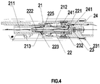
FIG. 4 shows the schematic view of the water flow when the switching shaft is in the second position; -
FIG. 5 shows the schematic view of the water flow when the switching shaft is in the third position; - With the following description of the drawings and specific embodiments, the invention shall be easier to understand.
- Referring to
FIG. 1 to FIG. 5 ,a shower,comprising:amain body 1 of the shower and aswitching valve spool 2;and saidmain body 1 comprising anoutlet cover 11 and ahandle 12 , theswitching valve spool 2 is disposed in thehandle 12. - Said switching
valve spool 2, comprising:afixed shaft 21 and aswitching shaft 22 which is coaxially linked with the fixedshaft 21 arranged in thefixed shaft 21;said switchingshaft 22 moves between the first position,the second position, and the third position along the axial direction within the fixedshaft 21 due to the linkage of said switchingshaft 22 and anoperating unit 3; - One end of said switching
shaft 22 is aninlet 221, other end is anoutlet 222, and an axial flow passage is formed along the axis;when said switchingshaft 22 is at in the first position, theinlet 221 is closed to form a state of waterstop;when said switchingshaft 22 is at the second position, saidinlet 221 is opened and anair intake 223 is formed between the side wall of theswitching shaft 22 closing to theoutlet 222 and thefixed shaft 21, when the water flows into thefixed shaft 21 from theoutlet 222, the air, due to the diameter of thefixed shaft 21 is larger than the diameter of saidoutlet 222, is sucked from saidair intake 223 under the the Venturi effect, and mixes with the water in the fixedshaft 21 to form an aerated spray;when said switchingshaft 22 is at the third position, saidinlet 221 remains open and saidair intake 223 is closed to achieve a non-aerated spray. - To sum up, said structure is to offer that, during the switching shaft moves in a-single direction ,the
inlet 221 is closed to achieve a state of waterstop, or theair intake 223 is closed and theinlet 221 is opened to achieve a state of a non-aerated spray, or theair intake 223 and theinlet 221 is opened simultaneously to achieve a state of an aerated spray. Therefore, it is more convenient to achieve the switching of three modes of waterstop,common water and functional water by the single-direction movement of theswitching shaft 22 . - In order to achieve that the
inlet 221 is closed while theswitching shaft 22 is at the first position, the preferred embodiment adores the structure below:
The structure also comprises afirst sealing unit 23 arranged coaxially with said switchingshaft 22, saidfirst sealing unit 23 is at the rear of theinlet 221 along the axial direction, when said switchingshaft 22 is at the first position, the end face of said inlet abuts against saidfirst sealing unit 23 to close saidinlet 221. - Specifically, said first sealing unit 23' s placement is:the side of said fixed
shaft 21 which is close to one side of saidinlet 221 connects to aninlet joint 24;a containingcavity 241 is arranged at the side of saidinlet joint 24 closing to theinlet 221;saidfirst sealing unit 23 is arranged in said containingcavity 241;the water flows from theinlet joint 24 to said containingcavity 241 and it could only go through said flow passage into saidfixed shaft 21. - In order to ensure the stability of the seal, the first sealing unit must maintain the condition of fitting into the end face of the inlet when the
first sealing unit 23 abuts theinlet 221 sealingly,otherwise the seal would be unreliable because the first sealing unit is pressed by theinlet 221 and then moves backward. In order to solve this problem, the two sides of saidfirst sealing unit 23 are arranged against oneelastic unit 231 and asupport unit 232 respectively along the axis;when said fixedshaft 21 is at the first position, saidelastic unit 231 produces holding power to thefirst sealing unit 23 to make it maintain the condition of fitting into saidinlet 221;when said switchingshaft 22 is at other positions, saidelastic unit 231 drives thefirst sealing unit 23 to reset to the initial position where thefirst sealing unit 23 abuts against thesupport unit 232. Due to the elastic reset force provided by theelastic unit 231, when the end face of theinlet 221 abuts against thefirst sealing unit 23,theelastic unit 231 provides elastic reset force which is in opposite direction to the pressure resistance of thefirst sealing unit 23, to make sure that thefirst sealing unit 23 would not move backward along the axial direction, so that thefirst sealing unit 23 maintains the condition of fitting into the end face of theinlet 221 . - Based on above-mentioned structure,said
support unit 232 has a hole arranged along the axis to let theinlet 221 of said switchingshaft 22 pass through the hole to enter said containingcavity 241;so that thesupport unit 232 would not impede the movement of theswitching shaft 22. In addition, in order to drive the water coming from theinlet joint 24 to get into the containingcavity 241 where theinlet 221 is located , the periphery of the supportingunit 232 also has a water inlet perpendicular to the axial direction, the water coming from theinlet joint 24 flows through the inlet and then enters said containingcavity 241. - Moreover, in order to ensure the reliability of the waterstop, as mentioned above, the water from the
inlet joint 24 to said containingcavity 241 could only pass through said flow passage into saidfixed shaft 21. So that there would not be water getting into thefixed shaft 21 after theinlet 221 is closed. But based on the above-mentioned structure, the water would pass the inlet of thesupport unit 232, which has the hole, and inevitably flow out of the hole. - In order to solve this problem, a
second sealing unit 224 arranged on the side of the outer wall of said switchingshaft 22 closing to theinlet 221, seals the gap between theswitching shaft 22 and the hole, so that the water in said containingcavity 241 could only pass through said flow passage into said fixedshaft 21. - Moreover, there is a proper gap between the side of said
first sealing unit 23 which is away from saidinlet 221 and the back end of said containingcavity 241;when said switchingshaft 22 is at the first position, the flow comes from the inlet of thesupport unit 232 to the containingcavity 241,so that both the front surface and the back surface of saidfirst sealing unit 23 are subjected to the pressure of the flow in the axial direction,the pressure is equal in magnitude and opposite in direction, and it forms a balance of the water pressure. So that theswitching shaft 22 does not need to overcome the resistance of the flow during its movement, the force for switching is lighter and it feels better in the hand. - In order to achieve the aerated spray, in the present embodiment, said
fixed shaft 21 has afirst cavity 211 and asecond cavity 212, which are mutually connected each other along the axial direction, the diameter of saidfirst cavity 211 is smaller than saidsecond cavity 212 so as to form astep surface 213 in the connection between thefirst cavity 211 and thesecond cavity 212;the water flows into saidfirst cavity 211 from the outlet of theswitching shaft 22; in order to achieve the Venturi effect, the diameter of thefirst cavity 211 is larger than the diameter of theoutlet 222 so that a sudden change of the flow area creates the Venturi effect when the water comes to thefirst cavity 211 from theoutlet 222. - A
third sealing unit 225 is arranged on side of said switchingshaft 22 closing to saidoutlet 222;saidthird sealing unit 225 moves toward the direction of thestep surface 213 during the movement of said switchingshaft 22 from the first position to the third position;when said switchingshaft 22 is at the second position, saidthird sealing unit 225 does not contact with thestep surface 213 so that the gap between the outer wall of said switchingshaft 22 and thestep surface 213 forms saidair intake 223;when said switchingshaft 22 is at the third position, saidthird sealing unit 225 abuts against thestep surface 213 so that saidair intake 223 is closed. Thus, the switch of the aerated spray and the non-aerated spray can be achieved. - Furthermore, said
operating unit 3 is a button that exposed on the outside of saidmain body 1, a fixedbase 13 is arranged in saidmain body 1; one end of said button is connected with the fixedbase 13 rotatingly, and the other end is a pressing end; - A swinging
block 14 is rotatingly connected to the fixedbase 13. When the pressing end of thebutton 3 is pressed down,the swingingblock 14 is swung by the extrusion of thebutton 3, said swingingblock 14 connects with atransmission block 15 , and the swing of the swingingblock 14 drives thetransmission block 15 to move in the axial direction; saidtransmission block 15 moves along the axial direction , driving the switchingshaft 22 to move. So that thebutton 3 drives the switchingshaft 22 to move backward along the axial direction, that is moving from the third position to the first position. - To achieve the forward movement of the switching
shaft 22 along the axial direction, areset unit 226 is arranged at the peripheral covering of said switchingshaft 22, one of the end of thereset unit 226 abuts against the switchingshaft 22 and other end abuts against thesupport unit 232;when said switchingshaft 22 moves from the third position to the first position,thereset unit 226 is compressed to accumulate the elastic restoring force. When thetransmission block 15 and the switchingshaft 22 do not abut against each other, the switchingshaft 22 moves from the first position to the third position under the elastic restoring force. The invention may be summarized as follows: The present invention discloses a switching valve spool,comprising:a fixed shaft and a switching shaft coaxially arranged in the fixed shaft; the switching shaft is linked with an operating unit and moves between the first position, the second position, and the third position in said fixed shaft along the axis;one end of the switching shaft is an inlet, other end is an outlet, a flow passage is formed along the axial direction between the inlet and the outlet;when the switching shaft is at the first position, the inlet is closed to achieve a state of waterstop;when the switching shaft is at the second position, the inlet is open and an air intake is formed between the side wall of the switching shaft closing to the outlet and the fixed shaft, when the water flows into the fixed shaft from the outlet, the air, due to the diameter of the fixed shaft is larger than the diameter of the outlet, sucked from the air intake under the the Venturi effect, mixes with the water in the fixed shaft to form an aerated spray;when the switching shaft is at the third position, the inlet remains open and the air intake is closed to form a non-aerated spray. - The invention has been described with reference to the preferred embodiments mentioned above;therefore it cannot limit the reference implementation of the invention. It is obvious to a person skilled in the art that structural modification and changes can be carried out without leaving the scope of the claims hereinafter and the description above. Therefore, the scope of protection of the rights is based on the scope of the claims.
Claims (12)
- A switching valve spool, wherein comprising: a fixed shaft and a switching shaft coaxially arranged in the fixed shaft; an operating unit is linked with the switching shaft and drives the switching shaft to move from one position to an another position in said fixed shaft along the axis;
One end of said switching shaft is an inlet and other end is an outlet, an axial flow passage is formed along the axial direction between the inlet and the outlet; an air intake is formed between the side wall of the switching shaft closing to the outlet and the fixed shaft; when the switching shaft is at said one position, the water flows into the fixed shaft from the outlet, due to the diameter of the fixed shaft is larger than the diameter of the outlet, the air is sucked from the air intake under the the Venturi effect into the fixed shaft and mixs with the water flow to form an aerated spray; when the switching shaft is at the another position, said inlet remains open and said air intake is closed to form a non-aerated spray. - The switching valve spool according to claim 1, wherein comprising: an other position is included besides said one position and said another position, when said switching shaft is at said other position, said inlet is closed to form a state of waterstop.
- The switching valve spool according to claim 2, wherein comprising: a first sealing unit, coaxially arranged with said switching shaft, is arranged at the rear of said inlet along the axial direction, when said switching shaft is at said other position, the end face of said inlet fits said first sealing unit to close said inlet.
- The switching valve spool according to claim 3, wherein comprising: the side of said fixed shaft closing to the inlet connects with an inlet joint; a containing cavity is located at the side of said inlet joint closing to the inlet; said first sealing unit is arranged in said containing cavity; the water coming from the inlet joint goes to said cavity and could only go through said flow passage to said fixed shaft.
- The switching valve spool according to claim 3 and/or 4 wherein comprising: said first sealing unit is arranged against an elastic unit and a support unit respectively at the two side of the unit along the axis; when said switching shaft is at said other position, said elastic unit produces holding power to the first sealing unit to make it maintain the condition of fitting into the end face of said inlet; when said switching shaft is at other positions, said elastic unit drives the first sealing unit to reset to the initial position.
- The switching valve spool according to claim 5 wherein comprising: said support unit has a hole arranged along the axis to let the inlet of said switching shaft pass through the hole to enter said containing cavity;
the outer region of the support unit has a inlet vertical to the axial direction, the water gets into said containing cavity after coming from the inlet joint. - The switching valve spool according to any one or more of claims 4 to 6 wherein comprising: there is a proper gap between the side of said first sealing which is away from said inlet and the back end of said containing cavity; when said switching shaft is at said other position, the flow comes from the inlet of the support unit to the containing cavity, so that said first sealing unit is subjected to the pressure of the flow along the front and the back of the axial direction, the pressure is equal in magnitude and opposite in direction and it forms a balance of the water pressure.
- The switching valve spool according to claim 6 and/or 7 wherein comprising: a second sealing unit is arranged on the outer wall of the switching shaft closing to the inlet, seals the gap between said switching shaft and the hole, so that the water in said containing cavity could only pass through said flow passage into said fixed shaft.
- The switching valve spool according to any one or more of claims 2 to 8 wherein comprising: a third sealing unit is arranged on the side of said switching shaft closing to said outlet; said fixed shaft has two cavities, which are a first cavity and a second cavity, mutually connected to each other along the axial direction, the diameter of said first cavity is less than said second cavity so as to form a step surface in the connection between the first cavity and the second cavity; the water flows into said first cavity from the outlet of the switching shaft;
during the movement of said switching shaft moving from said another position to the other position, said third sealing unit moves toward the direction of said step surface; when said switching shaft is at said one position, said third sealing unit has not contacted with the step surface so that the gap between the outer wall of said switching shaft and the step surface forms said air intake; when said switching shaft is at said other position, said third sealing unit abuts against the step surface so that said air intake is closed. - A shower, wherein comprising: a main body of the shower and a switching valve spool according to any one or more of claims 1 to 9;said main body of the shower comprises an outlet cover and a handle , said switching valve spool is arranged in the handle.
- The shower according to claim 10, wherein comprising: said operating unit is a button, a fixed base is arranged in said main body; one end of said button is connected with the fixed base rotatingly, and the other end is a pressing end;
said fixed base is also connected to a swinging block rotatingly, when the pressing end of said button is pressed down, said swinging block swings by the extrusion of the button, said swinging block is linked with a transmission block in the course of swinging, and the transmission block converts the swing of the swinging block to an axial movement; the transmission block drives the switching shaft when it moves along the axial direction. - The shower according to claim 10 and/or 11, comprising: a reset unit is arranged at the peripheral covering of the switching shaft, one end of the reset unit abuts against the switching shaft and other end abuts against the fixed shaft; when said switching shaft moves from said another position to said other position, said reset unit is compressed to accumulate the elastic restoring force.
Applications Claiming Priority (1)
| Application Number | Priority Date | Filing Date | Title |
|---|---|---|---|
| CN201710308529.3A CN108799550B (en) | 2017-05-04 | 2017-05-04 | A water stop switching valve core and shower head |
Publications (2)
| Publication Number | Publication Date |
|---|---|
| EP3398688A1 true EP3398688A1 (en) | 2018-11-07 |
| EP3398688B1 EP3398688B1 (en) | 2021-04-28 |
Family
ID=62116650
Family Applications (1)
| Application Number | Title | Priority Date | Filing Date |
|---|---|---|---|
| EP18000428.5A Active EP3398688B1 (en) | 2017-05-04 | 2018-05-04 | A switching valve spool and a shower |
Country Status (3)
| Country | Link |
|---|---|
| US (1) | US10799895B2 (en) |
| EP (1) | EP3398688B1 (en) |
| CN (1) | CN108799550B (en) |
Cited By (1)
| Publication number | Priority date | Publication date | Assignee | Title |
|---|---|---|---|---|
| US12343742B2 (en) * | 2023-04-27 | 2025-07-01 | Ting-Yen Kuo | Nozzle for use with a hose |
Families Citing this family (10)
| Publication number | Priority date | Publication date | Assignee | Title |
|---|---|---|---|---|
| CN109998718A (en) * | 2019-04-04 | 2019-07-12 | 厦门鼎尚卫浴有限公司 | Toothwash faucet extracts water outlet device |
| CN110624705B (en) * | 2019-10-25 | 2024-03-26 | 福建欣宇卫浴科技股份有限公司 | Gondola water faucet stagnant water structure and gondola water faucet subassembly |
| CN111075954B (en) * | 2019-12-31 | 2025-03-25 | 路达(厦门)工业有限公司 | Shower |
| CN113558509B (en) * | 2021-08-16 | 2025-02-18 | 惠达卫浴股份有限公司 | A soap shower |
| US12496595B2 (en) | 2021-09-10 | 2025-12-16 | As America, Inc. | Showerhead assembly with aeration |
| CN114060567B (en) * | 2021-11-03 | 2025-09-05 | 厦门建霖健康家居股份有限公司 | A switchable water spout and a pull-out faucet |
| CN114798207B (en) * | 2022-04-20 | 2026-01-02 | 箭牌家居集团股份有限公司 | Shower switching device |
| US12491522B2 (en) * | 2023-06-17 | 2025-12-09 | Fujian Xihe Sanitary Ware Technology Co., Ltd. | Water outlet device |
| GB2628682B (en) * | 2023-07-19 | 2025-04-30 | Kohler Mira Ltd | Fluid delivery device |
| CN118237183B (en) * | 2024-05-28 | 2024-09-13 | 泉州中飞塑业有限公司 | A water outlet switching device with pause function and shower head |
Citations (3)
| Publication number | Priority date | Publication date | Assignee | Title |
|---|---|---|---|---|
| US20090200401A1 (en) * | 2008-02-12 | 2009-08-13 | Esche John C | Sprayer assembly |
| EP3108964A1 (en) * | 2015-06-18 | 2016-12-28 | Xiamen Solex High-tech Industries Co., Ltd. | Double-functional button switch shower head |
| CN205904000U (en) * | 2016-07-01 | 2017-01-25 | 厦门松霖科技有限公司 | Stagnant water auto -change over device and gondola water faucet |
Family Cites Families (8)
| Publication number | Priority date | Publication date | Assignee | Title |
|---|---|---|---|---|
| US3820716A (en) * | 1973-01-11 | 1974-06-28 | Bowles Fluidics Corp | Fluidic oscillator for providing dynamic liquid spray patterns |
| DE19901704A1 (en) * | 1999-01-18 | 2000-08-03 | Hansgrohe Ag | Sanitary object, in particular hand shower, with a switching device for influencing a liquid flow |
| US8177147B2 (en) * | 2009-04-15 | 2012-05-15 | Ray Engel | Showerhead with rotatable oval spray pattern and handheld spray pattern controller |
| CN101934255A (en) * | 2009-07-01 | 2011-01-05 | 厦门松霖科技有限公司 | A double-sided switching shower |
| WO2011110080A1 (en) * | 2010-03-09 | 2011-09-15 | 厦门松霖科技有限公司 | Lever button switching shower head |
| CN204933764U (en) * | 2015-07-23 | 2016-01-06 | 谭健明 | A kind of push button changeover module and apply the gondola water faucet of this assembly |
| CN205260926U (en) * | 2015-12-31 | 2016-05-25 | 厦门松霖科技有限公司 | Diverter valve with arrange cold function |
| CN206860942U (en) * | 2017-05-04 | 2018-01-09 | 厦门松霖科技股份有限公司 | Sealing switches valve element and gondola water faucet |
-
2017
- 2017-05-04 CN CN201710308529.3A patent/CN108799550B/en active Active
-
2018
- 2018-04-27 US US15/964,715 patent/US10799895B2/en not_active Expired - Fee Related
- 2018-05-04 EP EP18000428.5A patent/EP3398688B1/en active Active
Patent Citations (3)
| Publication number | Priority date | Publication date | Assignee | Title |
|---|---|---|---|---|
| US20090200401A1 (en) * | 2008-02-12 | 2009-08-13 | Esche John C | Sprayer assembly |
| EP3108964A1 (en) * | 2015-06-18 | 2016-12-28 | Xiamen Solex High-tech Industries Co., Ltd. | Double-functional button switch shower head |
| CN205904000U (en) * | 2016-07-01 | 2017-01-25 | 厦门松霖科技有限公司 | Stagnant water auto -change over device and gondola water faucet |
Cited By (1)
| Publication number | Priority date | Publication date | Assignee | Title |
|---|---|---|---|---|
| US12343742B2 (en) * | 2023-04-27 | 2025-07-01 | Ting-Yen Kuo | Nozzle for use with a hose |
Also Published As
| Publication number | Publication date |
|---|---|
| CN108799550A (en) | 2018-11-13 |
| US10799895B2 (en) | 2020-10-13 |
| US20180318859A1 (en) | 2018-11-08 |
| CN108799550B (en) | 2025-01-28 |
| EP3398688B1 (en) | 2021-04-28 |
Similar Documents
| Publication | Publication Date | Title |
|---|---|---|
| US10799895B2 (en) | Switch valve spool and a shower | |
| CN103486318B (en) | A kind of pilot valve switching mechanism and apply the combination gondola water faucet of this mechanism | |
| CN204933765U (en) | A kind of pass water reset top-spraying gondola | |
| CN211117762U (en) | Go out water structure and tap | |
| CN205904000U (en) | Stagnant water auto -change over device and gondola water faucet | |
| WO2018129472A1 (en) | Shower system | |
| CN206468841U (en) | A kind of temperature-adjustable switch valve easy to identify | |
| CN205260926U (en) | Diverter valve with arrange cold function | |
| CN204724343U (en) | A kind of combination gondola water faucet of gravity handoff functionality | |
| CN212397045U (en) | Shower head with spray gun | |
| CN107983546A (en) | A kind of sealing is shower head switched | |
| CN111075954A (en) | Shower device | |
| CN112642600B (en) | A water outlet device with water stop and flow control | |
| CN107755111B (en) | Water stopping device and shower head | |
| CN206082889U (en) | Assembled watering can | |
| CN206860942U (en) | Sealing switches valve element and gondola water faucet | |
| CN208089997U (en) | Pulling out leading water route switching control unit | |
| CN206168592U (en) | Button switching mechanism and adopt this switching mechanism's gondola water faucet | |
| KR200449629Y1 (en) | Shower head | |
| CN111229487B (en) | A drip-proof shower head | |
| CN219187326U (en) | Hand-held flushing shower head | |
| CN109967274A (en) | The shower of energy switching water discharging | |
| CN201880611U (en) | Hidden shower head capable of switching form of water discharging | |
| CN203613607U (en) | Water outlet device with double gears | |
| CN206240664U (en) | Sealing is shower head switched |
Legal Events
| Date | Code | Title | Description |
|---|---|---|---|
| PUAI | Public reference made under article 153(3) epc to a published international application that has entered the european phase |
Free format text: ORIGINAL CODE: 0009012 |
|
| STAA | Information on the status of an ep patent application or granted ep patent |
Free format text: STATUS: THE APPLICATION HAS BEEN PUBLISHED |
|
| AK | Designated contracting states |
Kind code of ref document: A1 Designated state(s): AL AT BE BG CH CY CZ DE DK EE ES FI FR GB GR HR HU IE IS IT LI LT LU LV MC MK MT NL NO PL PT RO RS SE SI SK SM TR |
|
| AX | Request for extension of the european patent |
Extension state: BA ME |
|
| STAA | Information on the status of an ep patent application or granted ep patent |
Free format text: STATUS: REQUEST FOR EXAMINATION WAS MADE |
|
| 17P | Request for examination filed |
Effective date: 20190418 |
|
| RBV | Designated contracting states (corrected) |
Designated state(s): AL AT BE BG CH CY CZ DE DK EE ES FI FR GB GR HR HU IE IS IT LI LT LU LV MC MK MT NL NO PL PT RO RS SE SI SK SM TR |
|
| GRAP | Despatch of communication of intention to grant a patent |
Free format text: ORIGINAL CODE: EPIDOSNIGR1 |
|
| STAA | Information on the status of an ep patent application or granted ep patent |
Free format text: STATUS: GRANT OF PATENT IS INTENDED |
|
| RIC1 | Information provided on ipc code assigned before grant |
Ipc: F16K 11/07 20060101ALI20200917BHEP Ipc: B05B 12/00 20180101ALI20200917BHEP Ipc: B05B 1/18 20060101AFI20200917BHEP Ipc: B05B 1/30 20060101ALI20200917BHEP Ipc: B05B 1/16 20060101ALI20200917BHEP Ipc: B05B 7/04 20060101ALI20200917BHEP Ipc: E03C 1/04 20060101ALI20200917BHEP Ipc: F16K 11/00 20060101ALI20200917BHEP |
|
| INTG | Intention to grant announced |
Effective date: 20201013 |
|
| GRAS | Grant fee paid |
Free format text: ORIGINAL CODE: EPIDOSNIGR3 |
|
| GRAA | (expected) grant |
Free format text: ORIGINAL CODE: 0009210 |
|
| STAA | Information on the status of an ep patent application or granted ep patent |
Free format text: STATUS: THE PATENT HAS BEEN GRANTED |
|
| AK | Designated contracting states |
Kind code of ref document: B1 Designated state(s): AL AT BE BG CH CY CZ DE DK EE ES FI FR GB GR HR HU IE IS IT LI LT LU LV MC MK MT NL NO PL PT RO RS SE SI SK SM TR |
|
| REG | Reference to a national code |
Ref country code: GB Ref legal event code: FG4D |
|
| REG | Reference to a national code |
Ref country code: CH Ref legal event code: EP |
|
| REG | Reference to a national code |
Ref country code: AT Ref legal event code: REF Ref document number: 1386513 Country of ref document: AT Kind code of ref document: T Effective date: 20210515 |
|
| REG | Reference to a national code |
Ref country code: DE Ref legal event code: R096 Ref document number: 602018016020 Country of ref document: DE |
|
| REG | Reference to a national code |
Ref country code: IE Ref legal event code: FG4D |
|
| REG | Reference to a national code |
Ref country code: LT Ref legal event code: MG9D |
|
| REG | Reference to a national code |
Ref country code: AT Ref legal event code: MK05 Ref document number: 1386513 Country of ref document: AT Kind code of ref document: T Effective date: 20210428 |
|
| PG25 | Lapsed in a contracting state [announced via postgrant information from national office to epo] |
Ref country code: AT Free format text: LAPSE BECAUSE OF FAILURE TO SUBMIT A TRANSLATION OF THE DESCRIPTION OR TO PAY THE FEE WITHIN THE PRESCRIBED TIME-LIMIT Effective date: 20210428 Ref country code: BG Free format text: LAPSE BECAUSE OF FAILURE TO SUBMIT A TRANSLATION OF THE DESCRIPTION OR TO PAY THE FEE WITHIN THE PRESCRIBED TIME-LIMIT Effective date: 20210728 Ref country code: HR Free format text: LAPSE BECAUSE OF FAILURE TO SUBMIT A TRANSLATION OF THE DESCRIPTION OR TO PAY THE FEE WITHIN THE PRESCRIBED TIME-LIMIT Effective date: 20210428 Ref country code: NL Free format text: LAPSE BECAUSE OF FAILURE TO SUBMIT A TRANSLATION OF THE DESCRIPTION OR TO PAY THE FEE WITHIN THE PRESCRIBED TIME-LIMIT Effective date: 20210428 Ref country code: LT Free format text: LAPSE BECAUSE OF FAILURE TO SUBMIT A TRANSLATION OF THE DESCRIPTION OR TO PAY THE FEE WITHIN THE PRESCRIBED TIME-LIMIT Effective date: 20210428 Ref country code: FI Free format text: LAPSE BECAUSE OF FAILURE TO SUBMIT A TRANSLATION OF THE DESCRIPTION OR TO PAY THE FEE WITHIN THE PRESCRIBED TIME-LIMIT Effective date: 20210428 |
|
| PG25 | Lapsed in a contracting state [announced via postgrant information from national office to epo] |
Ref country code: LV Free format text: LAPSE BECAUSE OF FAILURE TO SUBMIT A TRANSLATION OF THE DESCRIPTION OR TO PAY THE FEE WITHIN THE PRESCRIBED TIME-LIMIT Effective date: 20210428 Ref country code: NO Free format text: LAPSE BECAUSE OF FAILURE TO SUBMIT A TRANSLATION OF THE DESCRIPTION OR TO PAY THE FEE WITHIN THE PRESCRIBED TIME-LIMIT Effective date: 20210728 Ref country code: PL Free format text: LAPSE BECAUSE OF FAILURE TO SUBMIT A TRANSLATION OF THE DESCRIPTION OR TO PAY THE FEE WITHIN THE PRESCRIBED TIME-LIMIT Effective date: 20210428 Ref country code: PT Free format text: LAPSE BECAUSE OF FAILURE TO SUBMIT A TRANSLATION OF THE DESCRIPTION OR TO PAY THE FEE WITHIN THE PRESCRIBED TIME-LIMIT Effective date: 20210830 Ref country code: RS Free format text: LAPSE BECAUSE OF FAILURE TO SUBMIT A TRANSLATION OF THE DESCRIPTION OR TO PAY THE FEE WITHIN THE PRESCRIBED TIME-LIMIT Effective date: 20210428 Ref country code: SE Free format text: LAPSE BECAUSE OF FAILURE TO SUBMIT A TRANSLATION OF THE DESCRIPTION OR TO PAY THE FEE WITHIN THE PRESCRIBED TIME-LIMIT Effective date: 20210428 Ref country code: IS Free format text: LAPSE BECAUSE OF FAILURE TO SUBMIT A TRANSLATION OF THE DESCRIPTION OR TO PAY THE FEE WITHIN THE PRESCRIBED TIME-LIMIT Effective date: 20210828 Ref country code: GR Free format text: LAPSE BECAUSE OF FAILURE TO SUBMIT A TRANSLATION OF THE DESCRIPTION OR TO PAY THE FEE WITHIN THE PRESCRIBED TIME-LIMIT Effective date: 20210729 |
|
| REG | Reference to a national code |
Ref country code: NL Ref legal event code: MP Effective date: 20210428 |
|
| REG | Reference to a national code |
Ref country code: CH Ref legal event code: PL |
|
| PG25 | Lapsed in a contracting state [announced via postgrant information from national office to epo] |
Ref country code: SM Free format text: LAPSE BECAUSE OF FAILURE TO SUBMIT A TRANSLATION OF THE DESCRIPTION OR TO PAY THE FEE WITHIN THE PRESCRIBED TIME-LIMIT Effective date: 20210428 Ref country code: SK Free format text: LAPSE BECAUSE OF FAILURE TO SUBMIT A TRANSLATION OF THE DESCRIPTION OR TO PAY THE FEE WITHIN THE PRESCRIBED TIME-LIMIT Effective date: 20210428 Ref country code: ES Free format text: LAPSE BECAUSE OF FAILURE TO SUBMIT A TRANSLATION OF THE DESCRIPTION OR TO PAY THE FEE WITHIN THE PRESCRIBED TIME-LIMIT Effective date: 20210428 Ref country code: EE Free format text: LAPSE BECAUSE OF FAILURE TO SUBMIT A TRANSLATION OF THE DESCRIPTION OR TO PAY THE FEE WITHIN THE PRESCRIBED TIME-LIMIT Effective date: 20210428 Ref country code: RO Free format text: LAPSE BECAUSE OF FAILURE TO SUBMIT A TRANSLATION OF THE DESCRIPTION OR TO PAY THE FEE WITHIN THE PRESCRIBED TIME-LIMIT Effective date: 20210428 Ref country code: CZ Free format text: LAPSE BECAUSE OF FAILURE TO SUBMIT A TRANSLATION OF THE DESCRIPTION OR TO PAY THE FEE WITHIN THE PRESCRIBED TIME-LIMIT Effective date: 20210428 Ref country code: DK Free format text: LAPSE BECAUSE OF FAILURE TO SUBMIT A TRANSLATION OF THE DESCRIPTION OR TO PAY THE FEE WITHIN THE PRESCRIBED TIME-LIMIT Effective date: 20210428 Ref country code: CH Free format text: LAPSE BECAUSE OF NON-PAYMENT OF DUE FEES Effective date: 20210531 Ref country code: MC Free format text: LAPSE BECAUSE OF FAILURE TO SUBMIT A TRANSLATION OF THE DESCRIPTION OR TO PAY THE FEE WITHIN THE PRESCRIBED TIME-LIMIT Effective date: 20210428 Ref country code: LI Free format text: LAPSE BECAUSE OF NON-PAYMENT OF DUE FEES Effective date: 20210531 Ref country code: LU Free format text: LAPSE BECAUSE OF NON-PAYMENT OF DUE FEES Effective date: 20210504 |
|
| REG | Reference to a national code |
Ref country code: DE Ref legal event code: R097 Ref document number: 602018016020 Country of ref document: DE |
|
| REG | Reference to a national code |
Ref country code: BE Ref legal event code: MM Effective date: 20210531 |
|
| PLBE | No opposition filed within time limit |
Free format text: ORIGINAL CODE: 0009261 |
|
| STAA | Information on the status of an ep patent application or granted ep patent |
Free format text: STATUS: NO OPPOSITION FILED WITHIN TIME LIMIT |
|
| 26N | No opposition filed |
Effective date: 20220131 |
|
| PG25 | Lapsed in a contracting state [announced via postgrant information from national office to epo] |
Ref country code: IE Free format text: LAPSE BECAUSE OF NON-PAYMENT OF DUE FEES Effective date: 20210504 |
|
| PG25 | Lapsed in a contracting state [announced via postgrant information from national office to epo] |
Ref country code: IS Free format text: LAPSE BECAUSE OF FAILURE TO SUBMIT A TRANSLATION OF THE DESCRIPTION OR TO PAY THE FEE WITHIN THE PRESCRIBED TIME-LIMIT Effective date: 20210828 Ref country code: FR Free format text: LAPSE BECAUSE OF NON-PAYMENT OF DUE FEES Effective date: 20210628 Ref country code: AL Free format text: LAPSE BECAUSE OF FAILURE TO SUBMIT A TRANSLATION OF THE DESCRIPTION OR TO PAY THE FEE WITHIN THE PRESCRIBED TIME-LIMIT Effective date: 20210428 |
|
| PG25 | Lapsed in a contracting state [announced via postgrant information from national office to epo] |
Ref country code: IT Free format text: LAPSE BECAUSE OF FAILURE TO SUBMIT A TRANSLATION OF THE DESCRIPTION OR TO PAY THE FEE WITHIN THE PRESCRIBED TIME-LIMIT Effective date: 20210428 Ref country code: BE Free format text: LAPSE BECAUSE OF NON-PAYMENT OF DUE FEES Effective date: 20210531 |
|
| GBPC | Gb: european patent ceased through non-payment of renewal fee |
Effective date: 20220504 |
|
| PG25 | Lapsed in a contracting state [announced via postgrant information from national office to epo] |
Ref country code: GB Free format text: LAPSE BECAUSE OF NON-PAYMENT OF DUE FEES Effective date: 20220504 |
|
| PG25 | Lapsed in a contracting state [announced via postgrant information from national office to epo] |
Ref country code: CY Free format text: LAPSE BECAUSE OF FAILURE TO SUBMIT A TRANSLATION OF THE DESCRIPTION OR TO PAY THE FEE WITHIN THE PRESCRIBED TIME-LIMIT Effective date: 20210428 |
|
| PG25 | Lapsed in a contracting state [announced via postgrant information from national office to epo] |
Ref country code: HU Free format text: LAPSE BECAUSE OF FAILURE TO SUBMIT A TRANSLATION OF THE DESCRIPTION OR TO PAY THE FEE WITHIN THE PRESCRIBED TIME-LIMIT; INVALID AB INITIO Effective date: 20180504 |
|
| PG25 | Lapsed in a contracting state [announced via postgrant information from national office to epo] |
Ref country code: MK Free format text: LAPSE BECAUSE OF FAILURE TO SUBMIT A TRANSLATION OF THE DESCRIPTION OR TO PAY THE FEE WITHIN THE PRESCRIBED TIME-LIMIT Effective date: 20210428 |
|
| PG25 | Lapsed in a contracting state [announced via postgrant information from national office to epo] |
Ref country code: MT Free format text: LAPSE BECAUSE OF FAILURE TO SUBMIT A TRANSLATION OF THE DESCRIPTION OR TO PAY THE FEE WITHIN THE PRESCRIBED TIME-LIMIT Effective date: 20210428 |
|
| PGFP | Annual fee paid to national office [announced via postgrant information from national office to epo] |
Ref country code: DE Payment date: 20250531 Year of fee payment: 8 |
|
| PG25 | Lapsed in a contracting state [announced via postgrant information from national office to epo] |
Ref country code: TR Free format text: LAPSE BECAUSE OF FAILURE TO SUBMIT A TRANSLATION OF THE DESCRIPTION OR TO PAY THE FEE WITHIN THE PRESCRIBED TIME-LIMIT Effective date: 20210428 |