EP3398581A1 - Self-standing drug-filled synthetic resin ampule - Google Patents
Self-standing drug-filled synthetic resin ampule Download PDFInfo
- Publication number
- EP3398581A1 EP3398581A1 EP16881727.8A EP16881727A EP3398581A1 EP 3398581 A1 EP3398581 A1 EP 3398581A1 EP 16881727 A EP16881727 A EP 16881727A EP 3398581 A1 EP3398581 A1 EP 3398581A1
- Authority
- EP
- European Patent Office
- Prior art keywords
- ampule
- drug
- synthetic resin
- pressing
- breakable
- Prior art date
- Legal status (The legal status is an assumption and is not a legal conclusion. Google has not performed a legal analysis and makes no representation as to the accuracy of the status listed.)
- Granted
Links
Images


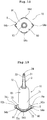


Classifications
-
- A—HUMAN NECESSITIES
- A61—MEDICAL OR VETERINARY SCIENCE; HYGIENE
- A61J—CONTAINERS SPECIALLY ADAPTED FOR MEDICAL OR PHARMACEUTICAL PURPOSES; DEVICES OR METHODS SPECIALLY ADAPTED FOR BRINGING PHARMACEUTICAL PRODUCTS INTO PARTICULAR PHYSICAL OR ADMINISTERING FORMS; DEVICES FOR ADMINISTERING FOOD OR MEDICINES ORALLY; BABY COMFORTERS; DEVICES FOR RECEIVING SPITTLE
- A61J1/00—Containers specially adapted for medical or pharmaceutical purposes
- A61J1/05—Containers specially adapted for medical or pharmaceutical purposes for collecting, storing or administering blood, plasma or medical fluids ; Infusion or perfusion containers
- A61J1/06—Ampoules or carpules
-
- A—HUMAN NECESSITIES
- A61—MEDICAL OR VETERINARY SCIENCE; HYGIENE
- A61J—CONTAINERS SPECIALLY ADAPTED FOR MEDICAL OR PHARMACEUTICAL PURPOSES; DEVICES OR METHODS SPECIALLY ADAPTED FOR BRINGING PHARMACEUTICAL PRODUCTS INTO PARTICULAR PHYSICAL OR ADMINISTERING FORMS; DEVICES FOR ADMINISTERING FOOD OR MEDICINES ORALLY; BABY COMFORTERS; DEVICES FOR RECEIVING SPITTLE
- A61J1/00—Containers specially adapted for medical or pharmaceutical purposes
- A61J1/05—Containers specially adapted for medical or pharmaceutical purposes for collecting, storing or administering blood, plasma or medical fluids ; Infusion or perfusion containers
- A61J1/06—Ampoules or carpules
- A61J1/065—Rigid ampoules, e.g. glass ampoules
-
- A—HUMAN NECESSITIES
- A61—MEDICAL OR VETERINARY SCIENCE; HYGIENE
- A61J—CONTAINERS SPECIALLY ADAPTED FOR MEDICAL OR PHARMACEUTICAL PURPOSES; DEVICES OR METHODS SPECIALLY ADAPTED FOR BRINGING PHARMACEUTICAL PRODUCTS INTO PARTICULAR PHYSICAL OR ADMINISTERING FORMS; DEVICES FOR ADMINISTERING FOOD OR MEDICINES ORALLY; BABY COMFORTERS; DEVICES FOR RECEIVING SPITTLE
- A61J1/00—Containers specially adapted for medical or pharmaceutical purposes
- A61J1/05—Containers specially adapted for medical or pharmaceutical purposes for collecting, storing or administering blood, plasma or medical fluids ; Infusion or perfusion containers
- A61J1/06—Ampoules or carpules
- A61J1/067—Flexible ampoules, the contents of which are expelled by squeezing
-
- A—HUMAN NECESSITIES
- A61—MEDICAL OR VETERINARY SCIENCE; HYGIENE
- A61J—CONTAINERS SPECIALLY ADAPTED FOR MEDICAL OR PHARMACEUTICAL PURPOSES; DEVICES OR METHODS SPECIALLY ADAPTED FOR BRINGING PHARMACEUTICAL PRODUCTS INTO PARTICULAR PHYSICAL OR ADMINISTERING FORMS; DEVICES FOR ADMINISTERING FOOD OR MEDICINES ORALLY; BABY COMFORTERS; DEVICES FOR RECEIVING SPITTLE
- A61J1/00—Containers specially adapted for medical or pharmaceutical purposes
- A61J1/14—Details; Accessories therefor
- A61J1/16—Holders for containers
-
- B—PERFORMING OPERATIONS; TRANSPORTING
- B65—CONVEYING; PACKING; STORING; HANDLING THIN OR FILAMENTARY MATERIAL
- B65D—CONTAINERS FOR STORAGE OR TRANSPORT OF ARTICLES OR MATERIALS, e.g. BAGS, BARRELS, BOTTLES, BOXES, CANS, CARTONS, CRATES, DRUMS, JARS, TANKS, HOPPERS, FORWARDING CONTAINERS; ACCESSORIES, CLOSURES, OR FITTINGS THEREFOR; PACKAGING ELEMENTS; PACKAGES
- B65D1/00—Rigid or semi-rigid containers having bodies formed in one piece, e.g. by casting metallic material, by moulding plastics, by blowing vitreous material, by throwing ceramic material, by moulding pulped fibrous material or by deep-drawing operations performed on sheet material
- B65D1/09—Ampoules
-
- B—PERFORMING OPERATIONS; TRANSPORTING
- B65—CONVEYING; PACKING; STORING; HANDLING THIN OR FILAMENTARY MATERIAL
- B65D—CONTAINERS FOR STORAGE OR TRANSPORT OF ARTICLES OR MATERIALS, e.g. BAGS, BARRELS, BOTTLES, BOXES, CANS, CARTONS, CRATES, DRUMS, JARS, TANKS, HOPPERS, FORWARDING CONTAINERS; ACCESSORIES, CLOSURES, OR FITTINGS THEREFOR; PACKAGING ELEMENTS; PACKAGES
- B65D1/00—Rigid or semi-rigid containers having bodies formed in one piece, e.g. by casting metallic material, by moulding plastics, by blowing vitreous material, by throwing ceramic material, by moulding pulped fibrous material or by deep-drawing operations performed on sheet material
- B65D1/09—Ampoules
- B65D1/095—Ampoules made of flexible material
-
- B—PERFORMING OPERATIONS; TRANSPORTING
- B65—CONVEYING; PACKING; STORING; HANDLING THIN OR FILAMENTARY MATERIAL
- B65D—CONTAINERS FOR STORAGE OR TRANSPORT OF ARTICLES OR MATERIALS, e.g. BAGS, BARRELS, BOTTLES, BOXES, CANS, CARTONS, CRATES, DRUMS, JARS, TANKS, HOPPERS, FORWARDING CONTAINERS; ACCESSORIES, CLOSURES, OR FITTINGS THEREFOR; PACKAGING ELEMENTS; PACKAGES
- B65D11/00—Containers having bodies formed by interconnecting or uniting two or more rigid, or substantially rigid, components made wholly or mainly of plastics material
- B65D11/02—Containers having bodies formed by interconnecting or uniting two or more rigid, or substantially rigid, components made wholly or mainly of plastics material of curved cross-section
-
- B—PERFORMING OPERATIONS; TRANSPORTING
- B65—CONVEYING; PACKING; STORING; HANDLING THIN OR FILAMENTARY MATERIAL
- B65D—CONTAINERS FOR STORAGE OR TRANSPORT OF ARTICLES OR MATERIALS, e.g. BAGS, BARRELS, BOTTLES, BOXES, CANS, CARTONS, CRATES, DRUMS, JARS, TANKS, HOPPERS, FORWARDING CONTAINERS; ACCESSORIES, CLOSURES, OR FITTINGS THEREFOR; PACKAGING ELEMENTS; PACKAGES
- B65D2207/00—Standing packages
Definitions
- the present invention relates to a drug-filled synthetic resin ampule which can be opened by performing a breaking operation.
- a synthetic resin ampule is disclosed in Japanese Patent Application Laid-Open Publication No. 2013-095436 (patent document 1).
- the plug part 5 connected communicably to the ampule body 3 through the intermediary of the neck part 4 formed along the spout 8
- the head part 7 connected to the plug part 5 through the intermediary of the thin plate-shaped edge part 6 projecting outward from the plug part 5, the arm plate 15 flat in the direction intersecting with the edge part 6 is formed at the head part 7.
- a synthetic resin ampule is disclosed in Japanese Patent Application Laid-Open Publication No. 2014-69856 (patent document 2).
- the synthetic resin ampule of the patent document 2 has the body part (1), having a bottomed tubular configuration made by means of biaxial stretching blow molding, which accommodates the content liquid (N), the topped tubular head part (6) formed erectly and continuously with the upper end of the body part (1), the weakening part (10) which is formed at the boundary between the body part (1) and the head part (6) and to be broken by a relative fluctuation between the body part (1) and the head part (6).
- a large number of vertical ribs (9) are circumferentially arranged in parallel with one another at the inner circumferential surface portion (7) to which the peripheral edge of the lower-end liquid surface (n1) of the remaining content liquid (N) positioned inside the head part (6) attaches to form the irregular surface portion (8) by disposing the vertical ribs (9) whose heights are different from one another at the upper ends mixedly with the irregular surface portion (8).
- a drug-filled synthetic resin ampule comprises an ampule body capable of standing by itself and a drug accommodated inside said ampule body, wherein said ampule body has a tip part positioned at an upper part thereof when the ampule body stands by itself, a hollow part having a drug accommodation portion, and a breakable part provided between a lower portion of said tip part and an upper portion of said hollow part; and said tip part has a pressing portion for guiding a pressing force applied thereto in a predetermined direction when an operation of breaking said breakable part is performed; said hollow part has a bottom surface part for allowing said ampule body to stand by itself; and said bottom surface part has an extension portion extended in said predetermined direction.
- a drug-filled synthetic resin ampule 1 of the present invention has an ampule body 2 capable of standing by itself and a drug 6 accommodated inside the ampule body 2.
- the ampule body 2 has a tip part 3 positioned at an upper part thereof when the ampule body stands by itself, a hollow part 21 having a drug accommodation portion 23, and a breakable part 5 provided between a lower portion of the tip part 3 and an upper portion of the hollow part 21.
- the tip part 3 has pressing portions 31, 32 for guiding a pressing force applied thereto in a predetermined direction when an operation of breaking the breakable part 5 is performed.
- the hollow part 21 has a bottom surface part 4 for allowing the ampule body to stand by itself.
- the bottom surface part 4 has extension portions 41, 42 extended in predetermined directions (X-direction, Y-direction) in which the pressing force applied to the pressing portions 31, 32 is guided when an operation of pressing the pressing portions 31, 32 is performed to break the breakable part.
- the drug-filled synthetic resin ampule 1, of the present invention has the ampule body 2 capable of standing by itself and the drug 6 accommodated inside the ampule body 2.
- the ampule body 2 has the tip part 3 positioned at the upper part thereof when the ampule body stands by itself, the hollow part 21 having the drug accommodation portion 23, and the breakable part 5 provided between the lower portion of the tip part 3 and the upper portion of the hollow part 21.
- the ampule body 2 capable of standing by itself has a tubular body 20 and a bottom plate member 40 sealing a lower-end opening of the tubular body 20.
- the tubular body 20 has the hollow part 21, the tip part 3, and the breakable part 5.
- the tubular body 20 has the lower-end opening and includes the hollow part 21 extended upward, the tip part 3 positioned upward from the hollow part, and the breakable part 5 provided between the lower portion of the tip part 3 and the upper portion of the hollow part 21, in other words, so provided as to form a boundary portion between the tip part 3 and the hollow part 21.
- the hollow part 21 has the drug accommodation portion 23. It is preferable that the volume of the drug accommodation portion 23 is 0.5 to 50ml.
- the hollow part 21 has a cylindrical portion extended a predetermined length in substantially the same outer and inner diameters and an inner-surface tapered portion 22 positioned upward from the cylindrical portion.
- the hollow part 21 has the inner-surface tapered portion 22 whose diameter decreases toward the breakable part 5.
- the tapered portion 22 may be formed by upward decreasing the diameters of the inner and outer surfaces thereof.
- the tubular body 20 can be formed by injection molding.
- the tubular body including the hollow material 21 by injection molding and thereafter mount the breakable material 5 on the formed tubular body by ultrasonic welding or high frequency welding.
- the entire tubular body 20 including the breakable material 5 may be formed by injection molding.
- the bottom surface part 4 may be mounted on the formed tubular body 20 by ultrasonic welding or high frequency welding.
- the inner diameter of the cylindrical portion is preferably 6 to 33mm and especially preferably 7 to 24mm.
- the outer diameter of the cylindrical portion is preferably 7 to 35mm and especially preferably 10 to 25mm.
- the inner diameter of the tapered portion 22 is preferably 3 to 12mm and especially preferably 3 to 9mm at a small-diameter portion thereof.
- the hollow part (drug accommodation portion 23) of the tubular body 20 transparently to allow the drug accommodated therein to be visible.
- the pressure inside the drug accommodation portion 23 of the tubular body 20 may be set normally, the pressure therein may be set to a decreased pressure state or a vacuum state. In a case where the pressure inside the drug accommodation portion is set to the decreased pressure state or the vacuum state, it is possible to increase the effect of preventing the drug from altering, decomposing and deteriorating.
- the drug 6 to be accommodated inside the drug accommodation portion includes any kind including a solid-state drug, for example, powdery, granular and a liquid-state drug.
- examples of the drug include analgesic agents such as morphine (narcotic analgesic agents), insulin, antitumor agents, cardiotonic agents, intravenous anesthetic agents, antiparkinson agents, tumor therapeutic agents, adrenocortical hormone agents, antiarrhythmic agents, correction electrolytes, antiviral agents, immunostimulant agents, antibiotics, local anesthetic agents such as xylocaine, vitamins, multivitamin preparations, various amino acids, anti-thrombotic agents such as heparin.
- Drugs such as the narcotic analgesic agents and the antitumor agents needed to be handled and managed with care are preferable as the drug to be accommodated inside the drug accommodation portion.
- the breakable part 5 is a thin and fragile part provided in the vicinity of the boundary portion between the drug accommodation portion 23 and the tip part 3.
- the thin and fragile part (breakable part) is formed of an annular groove formed on an outer surface of the tubular body 20. More specifically, the thin and fragile part is formed on the outer surface of an upper-end portion of the tapered portion 22 of the tubular body 20.
- a groove-formed portion is V-shaped in its sectional configuration. More specifically, the angle of the groove-formed portion in its section is preferably 30 to 90 degrees and especially preferably 40 to 50 degrees.
- the groove-formed portion having an angle in the above-described range allows a stress to concentrate on the center of the breakable part when the tip part 3 is bent. Thereby the breakable part is securely broken.
- the groove-formed portion may be formed in any configuration so long as its configuration is easily breakable.
- its configuration may be semicircular, semi-elliptic or the like.
- the groove-formed portion may be so formed that its thickness is relatively smaller than that of the neighborhood thereof to easily break the groove-formed portion.
- the breakable part may be formed of a material more fragile than that of other portions of the tubular body. More specifically, it is preferable to use multicolor molding to annularly form only the neighborhood of the breakable part of a material which can be easily broken. Other portions of the tubular body are made of a material which cannot be easily broken.
- the groove-formed portion is formed annularly and continuously on the entire outer circumference of the drug accommodation portion, the groove-formed portion may be intermittently formed on the entire outer circumference thereof.
- the tip part 3 forms the upper part of the ampule body 2 and is positioned at an upper part of the tubular body 20.
- the tip part 3 has the pressing portions 31, 32 for guiding the pressing force applied thereto in the predetermined direction when the operation of breaking the breakable part 5 is performed.
- the hollow part 21 has the bottom surface part 4 for allowing the ampule body to stand by itself.
- the bottom surface part 4 allows the ampule 1 to stand by itself with the upper portion of the hollow part facing upward and with the front end of the tip part 3 also facing upward. It is preferable that the ampule 1 stands by itself without staggering. But the ampule may swing or tilt to some extent. In a case where the ampule swings or tilts, it is preferable that the ampule is to swing or tilt in the first predetermined direction (X direction) for breaking operation of a breakable portion 5 or a direction (Y-direction) opposite to the first predetermined direction.
- the bottom surface part 4 is substantially flat and thus, the synthetic resin ampule 1 is allowed to stand by itself without staggering with the tip part 3 being substantially erect.
- the central portion thereof may be hollow.
- the bottom surface part may have an annular projected portion for allowing the ampule to stand by itself.
- the tip part 3 has the first pressing portion 31 for performing the operation of breaking the breakable part 5 and guiding the pressing force applied thereto in the first predetermined direction (X-direction), and a second pressing portion 32 for performing the operation of breaking the breakable part 5 and guiding the pressing force applied thereto in the direction (Y-direction) opposite to the first predetermined direction.
- the bottom surface part 4 has the extension portion 41 extended in the predetermined direction (X-direction) in which the pressing force applied to the pressing portion 31 is guided when the operation of pressing the pressing portion 31 is performed to break breakable part.
- the bottom surface part 4 has the extension portion 42 extended in the predetermined direction (Y-direction) in which the pressing force applied to the pressing portion 32 is guided when the operation of pressing the pressing portion 32 is performed to break breakable part.
- the ampule body 2 does not have a drug-storable portion, which is a general configuration of a glass ampule, in an upper portion than said breakable part including said tip part.
- the drug liquid medicine in particular
- the tip part 3 is solid.
- the tip part does not necessarily need to be perfectly solid but may have an occluded lumen therein.
- the breakable part 5 is formed of the groove formed on the outer surface of the tubular body, as described above and does not constitute an inwardly projected portion.
- the ampule body does not have a drug storage portion although the ampule body has the breakable part.
- the tip part 3 has a plate-shaped body portion 34 and a plurality of ribs formed on both surfaces of the plate-shaped body portion 34 by extending the ribs axially with the ribs being vertical to the plate-shaped body portion.
- Ribs 31a, 31b, and 31c are formed at the side of the first pressing portion 31 by extending the ribs axially (upward and downward direction).
- the first pressing portion 31 is formed of upper portions of the ribs 31a, 31b, and 31c formed on an outer surface of the plate-shaped body portion 34 by axially (upward and downward direction) extending them.
- the upper portions of the ribs 31a, 31b, and 31c are projected from the plate-shaped body portion 34 in substantially the same height.
- the pressing direction is orthogonal to a surface (imaginary plane) formed of the first pressing portion 31.
- the pressing direction is referred to as the first predetermined direction (X-direction). Therefore, by pressing the first pressing portion 31 with fingers or the like, the tip part 3 is pressed in the X-direction. Thereby the breakable part 5 starts to be broken below the first pressing portion 31. With the progress of the breakage, the tip part 3 falls over in the X-direction.
- the ribs 31a, 31b, and 31c extend downward from the pressing portion 31, and the protruding lengths of these ribs increase downward.
- the rib reinforces the whole of the tip portion 3.
- the second pressing portion 32 for performing the operation of breaking the breakable part 5 and guiding the pressing force applied thereto in the second predetermined direction (Y-direction).
- ribs 32a, 32b, and 32c are formed at the side of the second pressing portion 32 by extending the ribs axially (upward and downward direction).
- the second pressing portion 32 is formed of upper portions of the ribs 32a, 32b, and 32c formed on the outer surface of the plate-shaped body portion 34 by axially (upward and downward direction) extending them.
- the upper portions of the ribs 32a, 32b, and 32c are projected from the plate-shaped body portion 34 in substantially the same height.
- the second pressing portion can be favorably pressed with fingers.
- the pressing direction is orthogonal to a surface (imaginary plane) formed of the second pressing portion 32.
- the pressing direction is referred to as the second predetermined direction (Y-direction). Therefore, by pressing the second pressing portion 32 with fingers or the like, the tip part 3 is pressed in the Y-direction. Thereby the breakable part 5 starts to be broken below the second pressing portion 32. With the progress of the breakage, the tip part 3 falls over in the Y-direction.
- the ribs 32a, 32b, and 32c extend downward from the pressing portion 32, and the protruding lengths of these ribs increase downward.
- the rib reinforces the whole of the tip portion 3.
- the pressing portions 31, 32 may be formed.
- the pressing portions may be formed not of the above-described ribs, but of a flat plate portion.
- the ampule body 2 has the extension portion 41 extended in the predetermined direction (X-direction) in which the pressing force applied to the pressing portion 31 is guided when the operation of pressing the pressing portion 31 is performed to break the breakable part and the extension portion 42 extended in the predetermined direction (Y-direction) in which the pressing force applied to the pressing portion 32 is guided when the operation of pressing the pressing portion 32 is performed to break the breakable part.
- the extension portions 41, 42 are formed at the bottom surface part of the ampule body 2.
- the bottom surface part 4 is formed of the bottom plate member 40.
- the bottom plate member 40 of this embodiment has a plate-shaped bottom plate body and a tubular portion 43 extended upward from an upper surface of the bottom plate body.
- the tubular portion 43 is in penetration into a lower-end opening 24 of the tubular body 20.
- the bottom plate member 40 forming the bottom surface part 4 has the first extension portion 41 extended outward (radially outward) from a lower-end surface of the tubular body 20.
- the first extension portion 41 is extended in the first predetermined direction (X-direction) in which the pressing force applied to the pressing portion 31 is guided when the operation of pressing the pressing portion 31 is performed to break the breakable part.
- X-direction first predetermined direction
- the extension portion 41 provided on the bottom surface 4 (bottom plate member 40) serves as a support, the pressing force applied to the pressing portion 31 can be securely transmitted to the breakable part.
- the breakable part can be easily broken.
- the bottom plate member 40 forming the bottom surface part 4 has the second extension portion 42 extended outward (radially outward) from the lower-end surface of the tubular body 20.
- the second extension portion 42 is so disposed as to oppose the first extension portion 41.
- the second extension portion 42 is extended in the second predetermined direction (Y-direction) in which the pressing force applied to the pressing portion 32 is guided when the operation of pressing the pressing portion 32 is performed to break the breakable part.
- the extension portion 42 provided on the bottom surface 4 (bottom plate member 40) serves as a support, the pressing force applied to the pressing portion 32 can be securely transmitted to the breakable part.
- the breakable part can be easily broken.
- the bottom plate member 40 forming the bottom surface part 4 has two more extension portions 47, 48 extended outward (radially outward) from the lower-end surface of the tubular body 20.
- the extension portions 47, 48 are so disposed as to be opposed to each other.
- the extension portions 47, 48 are so disposed that an imaginary line connecting the extension portions 47, 48 to each other is substantially orthogonal to an imaginary line connecting the extension portions 31, 32 to each other.
- the outer configuration of the bottom surface part 4 (bottom plate member 40) is rectangular, more specifically, almost square. Thus, when the ampule 1 falls over, the ampule is prevented from rotating or swinging.
- the bottom surface part of the drug-filled synthetic resin ampule, of the present invention may have the form of an ampule 1a of an embodiment shown in Fig. 5 .
- a bottom surface part 4a has only two opposed extension portions 41a, 42a.
- the extension portion 41a is extended in the X-direction
- the extension portion 42a is extended in the Y-direction.
- An outer edge of each of the extension portions 41a, 41b is rounded.
- the bottom surface part 4a of the ampule 1a of this embodiment does not have any extension portion other than the extension portions 41a, 41b.
- the distance from the center of the bottom surface part 4a to an outer edge of each of the extension portions 41a, 42a is longest of all distances from the center of the bottom surface part 4a to outer edges thereof.
- the ampule 1a because the ampule 1a is provided with the extension portion, the ampule can be prevented from rolling when the ampule falls over.
- the bottom surface part of the drug-filled synthetic resin ampule of the present invention may have a form of an ampule 1b of an embodiment shown in Fig. 6 .
- a bottom surface part 4b has only two opposed extension portions 41b, 42b.
- the extension portion 41b is extended in the X-direction, whereas the extension portion 42b is extended in the Y-direction.
- An outer edge of each of the extension portions 41b, 42b is rounded.
- the bottom surface part 4b of this embodiment does not have any extension portion other than the extension portions 41b, 42b.
- the extension portion 41b is formed longer than the extension portion 42b in its extension length.
- the distance from the center of the bottom surface part 4b to an outer edge of the extension portion 41b is longest of all distances from the center of the bottom surface part 4b to outer edges thereof.
- the ampule 1b because the ampule 1b is provided with the extension portion, the ampule can be prevented from rolling when the ampule falls over.
- the bottom surface part of the drug-filled synthetic resin ampule of the present invention may have a form of an ampule 1c of an embodiment shown in Fig. 7 .
- a bottom surface part 4c has only one extension portion 41c.
- the extension portion 41c is extended in the X-direction.
- An outer edge of the extension portion 41c is rounded.
- the bottom surface part 4c of this embodiment does not have any extension portion other than the extension portion 41c.
- the distance from the center of the bottom surface part 4c to an outer edge of the extension portion 41c is longest of all distances from the center of the bottom surface part 4c to outer edges thereof.
- the ampule 1c because the ampule 1c is provided with the extension portion, the ampule can be prevented from rolling when the ampule falls over.
- a drug-filled synthetic resin ampule 1d of an embodiment shown in Figs. 8 through 11 is described below.
- the difference between the drug-filled synthetic resin ampule 1d of this embodiment and the ampule 1 of the above-described embodiment lies in the difference between the formation forms of both bottom surface parts, more specifically, in the difference between the forms of the lower parts of tubular bodies of both ampules and between the forms of bottom plate members of both ampules.
- the forms of other parts of both ampules are the same. Refer parts of the ampule 1d denoted by the same reference numerals as those used for the ampule 1 to the above-described description.
- a tubular body 20a of an ampule body 2a has a hollow part 21a extended upward, the tip part 3 positioned upward from the hollow part, and the breakable part 5 provided between the lower portion of the tip part 3 and the upper portion of the hollow part 21a, in other words, so provided as to form a boundary portion between the tip part 3 and the hollow part 21a.
- the tubular body 20a of the ampule body 2a has bulge portions 25, 26 extended outward from a lower-end opening of the tubular body 20a.
- a bottom surface part 4d has extension portions 25a and 26a formed by a lower surface of the bulge portion 25 and that of the bulge portion 26 respectively.
- the tubular body 20a has a first bulge portion 25 bulged outward (radially outward) from its lower end.
- the lower surface of the bulge portion 25 is formed as a flat surface which forms a first extension portion 25a.
- the first extension portion 25a is extended in the first predetermined direction (X-direction) in which the pressing force applied to the pressing portion 31 is guided when the operation of pressing the pressing portion is performed to break the breakable part.
- the tubular body 20a has a second bulge portion 26 bulged outward (radially outward) from its lower end.
- the lower surface of the bulge portion 26 is formed as a flat surface which forms a second extension portion 26a.
- the second extension portion 26a is extended in the second predetermined direction (Y-direction) in which the pressing force applied to the pressing portion 32 is guided when the operation of pressing the pressing portion is performed to break the breakable part.
- the bottom plate member 40a sealing the lower-end opening of the tubular body 20a has a form fittable into a concave portion formed on a lower-end surface of the tubular body 20a. An outer edge of the bottom plate member 40a does not reach an outer edge of the tubular body 20a.
- the bottom surface part 4d has only the two extension portions 25a, 26a (bulge portions 25, 26) opposed to each other.
- the bottom surface part 4d of this embodiment does not have an extension portion other than the extension portions 25a, 26a.
- the distance from the center of the bottom surface part 4d to an outer edge of each of the extension portions 25a, 26a is longest of all distances from the center of the bottom surface part 4b to outer edges thereof.
- the bottom surface part of the ampule 1d may be provided with four extension portions.
- the bottom surface part of the ampule 1d may be provided with only one extension portion. More specifically, as with the above-described ampule 1c, the bottom surface part of the ampule 1d may be provided with only the bulge portion 25 (extension portion 25a) or only the bulge portion 26 (extension portion 26a).
- the bulge portion of the tubular body may be formed as a hollow part like a drug-filled synthetic resin ampule 1e of an embodiment shown in Fig. 12 .
- a tubular body 20c is hollow at its lower-end portion and has the bulge portions 25, 26 bulged outward.
- the extension portions 25a, 26a are formed of lower-end surfaces of these bulge portions and an outer edge of a bottom plate member 40c.
- the tubular body may have a lower bulge portion.
- the bulge portion may be formed as a hollow portion like a synthetic resin ampule 1f of an embodiment shown in Fig. 13 .
- a tubular body 20b is hollow at its lower end portion and has the bulge portions 25, 26 bulged outward.
- Extension portions 41, 42 is formed by an outer edge of a bottom plate member 40b mounted on the tubular body.
- bottom plate members of all the embodiments may have a conical upper surface 45 tilting toward the center of a bottom surface portion of a drug accommodation portion
- an upper surface of an insertion portion 44 inserted into the tubular body is formed as a conical upper surface 45 whose diameter decreases toward the center of the bottom plate member 40d.
- the conical upper surface may be formed as a polygonal pyramidal upper surface.
- the drug-filled synthetic resin ampule of the present invention is sterilized by subjecting the ampule to pressurized steam with a drug being filled and sealed therein. It is especially preferable to sterilize the ampule by subjecting it to the pressurized steam at a temperature of not less than 120 degrees C. More specifically, as a condition of the pressurized steam sterilization, an overkill condition (ISO/TS 17665-2) having a temperature of 121 degrees C and a period of time of fifteen minutes is preferable.
- ISO/TS 17665-2 an overkill condition having a temperature of 121 degrees C and a period of time of fifteen minutes
- materials for composing the drug-filled synthetic resin ampule body those which can be sterilized with pressurized steam are preferable.
- Materials applicable to the above-described overkill condition are especially preferable.
- materials for composing the ampule body includes various resins such as hard polyvinyl chloride, polyethylene, polypropylene, polybutadiene, and cyclic polyolefin.
- polyolefin such as ZEONEX (Nippon Zeon Co., Ltd.), APEL (Mitsui Chemicals, Inc), polypropylene homopolymer, high-density polyethylene; polystyrene, poly-(4-methylpentene-1), polycarbonate, ABS resin, acrylic resin, polymethylmethacrylate (PMMA), polyacetal, polyarylate, polyacrylonitrile, polyvinylidene fluoride, ionomer, acrylonitrile-butadiene-styrene copolymer, polyester such as polyethylene terephthalate (PET), polybutylene terephthalate (PBT), butadiene-styrene copolymer, aromatic or aliphatic polyamide, and combinations of these resins.
- PET polyethylene terephthalate
- PBT polybutylene terephthalate
- butadiene-styrene copolymer aromatic or aliphatic polyamide, and combinations of these resins
- the synthetic resin ampule body of the present invention is molded by means of injection molding.
- various hard resins suitable for the injection molding it is preferable to use various hard resins suitable for the injection molding.
- a drug-filled synthetic resin ampule of an embodiment, shown in Figs. 15 through 24 is described below.
- a drug-filled synthetic resin ampule 10 of this embodiment has an ampule body 7 capable of standing by itself and the drug 6 accommodated inside the ampule body 7.
- the ampule body 7 has the tip part 3 positioned at an upper portion thereof when the ampule body stands by itself, a hollow part 71 having a drug accommodation portion 78, and the breakable part 5 provided between the lower portion of the tip part 3 and an upper portion of the hollow part 71.
- the tip part 3 has the pressing portions 31, 32 for guiding the pressing force applied thereto respectively in the predetermined direction when the operation of breaking the breakable part 5 is performed.
- the hollow part 71 has a bottom surface part 9 for allowing the ampule body to stand by itself.
- the bottom surface part 9 has extension portions 92a, 92b extended in the predetermined directions (X-direction, Y-direction) in which the pressing force applied to the pressing portions 31, 32 respectively is guided when the operation of pressing the pressing portions 31, 32 is performed to break the breakable part.
- the drug-filled synthetic resin ampule 10 of this embodiment has the ampule body 7 capable of standing by itself and the drug 6 accommodated inside the ampule body 7.
- the ampule body 7 has a tubular body 70 and a bottom plate member 90 sealing a lower-end opening of the tubular body 70.
- the basic construction of the drug-filled synthetic resin ampule 10 of this embodiment is the same as that of the above-described drug-filled synthetic resin ampule 1.
- the main difference between the ampules 10 and 1 lies in the difference between the construction of the bottom surface part 9 of the ampule 10 and that of the bottom surface part of the ampule 1 and the form of the upper portion of the hollow part 71 of the tubular body 70 of the ampule 10 and that of the upper portion of the hollow part of the tubular body of the ampule 1.
- the ampule body 7 has the tip part 3 positioned at the upper part thereof when the ampule body stands by itself, the hollow part 71 having the drug accommodation portion 78, and the breakable part 5 provided between the lower portion of the tip part 3 and the upper portion of the hollow part 71.
- the ampule body 7 capable of standing by itself has the tubular body 70 and the bottom plate member 90 sealing the lower-end opening of the tubular body 70.
- the tubular body 70 has the hollow part 71, the tip part 3, and the breakable part 5.
- the tubular body 70 has the lower-end opening and includes the hollow part 71 extended upward, the tip part 3 positioned upward from the hollow part, and the breakable part 5 provided between the lower portion of the tip part 3 and the upper portion of the hollow part 71, in other words, so provided as to form a boundary portion between the tip part 3 and the hollow part 71.
- the hollow part 71 has the drug accommodation portion 78. It is preferable that the volume of the drug accommodation portion 78 is 0.5 to 50ml.
- the hollow part 71 has a cylindrical portion extended a predetermined length in substantially the same outer and inner diameters and a diameter-decreased portion 72 positioned upward from the cylindrical portion.
- both the inner and outer diameters of the hollow part 71 decrease toward the breakable part 5.
- the diameter-decreased portion 72 has a curved inner surface portion 72a whose diameter decreases curvedly from a front end of the cylindrical portion and a cylindrical inner surface portion 72b extended in an almost equal diameter from a front end of the curved inner surface portion 72a to an inner bottom surface part 33 of the tip part 3.
- the breakable part 5 is positioned at the cylindrical inner surface portion 72b, more specifically, at an upper portion (portion proximate to inner bottom surface part 33 of tip part 3) of the cylindrical inner surface portion 72b.
- the tubular body 70 can be molded by means of injection molding.
- the bottom plate member 90 is mounted on the tubular body 70 by means of ultrasonic welding or high frequency welding.
- the inner diameter of the cylindrical portion of the tubular body 70 is preferably 6 to 33mm and especially preferably 7 to 24mm.
- the outer diameter of the cylindrical portion is preferably 7 to 35mm and especially preferably 10 to 25mm.
- the inner diameter of the cylindrical inner surface portion 72b of the diameter-decreased portion 72 is preferably 3 to 12mm and especially preferably 3 to 9mm.
- the pressure inside the drug accommodation portion 78 of the tubular body 70 may be set normally, the pressure therein may be set to a decreased pressure state or a vacuum state in a case where resin used has gas barrier properties. In a case where the pressure inside the drug accommodation portion is set to the decreased pressure state or the vacuum state, it is possible to increase the effect of preventing the drug from deteriorating and decomposing due to a change in its quality.
- the drug 6 to be accommodated inside the drug accommodation portion 78 those described above are used.
- the breakable part 5 is a thin and fragile part provided in the vicinity of the boundary portion between the drug accommodation portion 78 and the tip part 3.
- the thin and fragile part (breakable part) is formed of an annular groove formed on an outer surface of the tubular body 70. More specifically, the thin and fragile part is formed on the outer surface of an upper-end portion of the diameter-decreased portion 72 of the tubular body 70.
- the angle of the groove-formed portion in its section is preferably 30 to 90 degrees and especially preferably 50 to 70 degrees.
- the groove-formed portion having an angle in the above-described range allows a stress to concentrate on the center of the breakable part when the tip part 3 is bent. Thereby the breakable part is securely broken.
- the thickness of the tubular body 70 at the breakable part 5 thereof is preferably 0.05 to 0.5mm and especially preferably 0.1 to 0.4mm.
- the breakable part and the groove-formed portion may be formed in any configuration so long as the configurations thereof are easily breakable.
- the configurations thereof may be semicircular, semi-elliptic or the like.
- the groove-formed portion may be so formed that its thickness is relatively smaller than that of the neighborhood thereof to easily break the groove-formed portion.
- the breakable part may be formed of a material more fragile than that of other portions of the tubular body. More specifically, it is preferable to use multicolor molding to annularly form only the neighborhood of the breakable part of a material which can be easily broken. Other portions of the tubular body are made of a material which cannot be easily broken.
- the groove-formed portion is formed annularly and continuously on the entire outer circumference of the drug accommodation portion, the groove-formed portion may be intermittently formed on the entire outer circumference thereof.
- the tip part 3 forms the upper part of the ampule body 7 and is positioned at an upper part of the tubular body 70.
- the tip part 3 has the pressing portions 31, 32 for guiding the pressing force applied thereto in the predetermined direction when the operation of breaking the breakable part 5 is performed.
- the tip part 3 is the same as that described on the above-described synthetic resin ampule 1.
- the ampule 10 of this embodiment has the bottom surface part 9 for allowing the ampule to stand by itself. Because the synthetic resin ampule 10 has the bottom surface part 9, the ampule is allowed to stand by itself with the upper portion of the hollow part facing upward and with the front end of the tip part 3 also facing upward. It is preferable that the synthetic resin ampule 10 stands by itself without staggering. In a case where the ampule swings or tilts, it is preferable that the ampule does so to allow the operation of breaking the breakable part 5 to be performed and in addition in the first predetermined direction (X-direction) or the direction (Y-direction) opposite to the first predetermined direction.
- the tip part 3 By pressing the first pressing portion 31 with fingers or the like, the tip part 3 is pressed in the X-direction. Thereby the breakable part 5 starts to be broken below the first pressing portion 31. With the progress of the breakage, the tip part 3 falls over in the X-direction. Similarly, by pressing the second pressing portion 32 with fingers or the like, the tip part 3 is pressed in the Y-direction. Thereby the breakable part 5 starts to be broken below the second pressing portion 32. With the progress of the breakage, the tip part 3 falls over in the Y-direction.
- the bottom surface part 9 has the extension portion 92a extended in the predetermined direction (Y-direction) in which the pressing force applied to the pressing portion 32 is guided when the operation of pressing the pressing portion 32 of the tip part 3 is performed to break the breakable part and the extension portion 92b extended in the predetermined direction (X-direction) in which the pressing force applied to the pressing portion 31 is guided when the operation of pressing the pressing portion 31 of the tip part 3 is performed to break the breakable part.
- the bottom surface part 9 is formed of the bottom plate member 90 and a flange portion 73 provided at a lower end 77 of the tubular body 70. More specifically, in the ampule 10 of this embodiment, the ampule body 7 has the flange portion 73, provided at the lower end 77 of the hollow part, which is extended outward and the bottom plate member 90 which seals an opening formed at the lower end 77 of the hollow part and whose upper surface is in contact with a lower surface of the flange portion 73. Because the bottom surface part 9 is formed of the flange portion and the bottom plate member 90 on which the flange portion is layered, the bottom surface part 9 has a sufficiently high degree of strength and rigidity.
- the flange portion 73 of the tubular body 70 is extended outward from the lower end 77 of the outer tube body 70 and is disk-shaped.
- the flange portion 73 has a substantially uniform thickness.
- the flange portion 73 has two concave portions 74a, 74b opposed to each other.
- the concave portions 74a, 74b are formed wavily.
- the flange portion 73 has two curved corners 75a, 75b opposed to each other.
- An outer edge of the flange portion 73 connecting the concave portions 74a and 74b to each other and an outer edge thereof connecting the curved corners 75a and 75b to each other are extended substantially linearly.
- the flange portion 73 is rectangular plate-shaped, and one pair of corners opposed to each other has the concave portions, whereas another pair of corners opposed to each other has the curved corners.
- the bottom plate member 90 has a base plate part 91 and extension portions 92a, 92b positioned at opposed corners of the base plate part 91.
- the extension portion 92a is extended in the predetermined direction (Y-direction) in which the pressing force applied to the pressing portion 32 of the tip part 3 is guided when the operation of pressing the pressing portion 32 is performed to break the breakable part.
- the extension portion 92b is extended in the predetermined direction (X-direction) in which the pressing force applied to the pressing portion 31 of the tip part 3 is guided when the operation of pressing the pressing portion 31 is performed to break the breakable part.
- Each of the extension portions 92a, 92b is formed as a projected portion projected upward.
- the extension portions 92a, 92b form approximately heart-shaped projections whose central concave portions are opposed to each other.
- Each of the extension portions 92a, 92b has a bulge portion formed at both sides of the central concave portion.
- the extension portion 92a is in engagement with the concave portion 74a of the flange portion 73, whereas the extension portion 92b is in engagement with the concave portion 74b of the flange portion 73.
- the bottom plate member 90 of this embodiment has an annular rib 95 formed on an upper surface of the base plate part 91. As shown in Fig.
- the annular rib 95 enters an open portion of the lower end 77 of tubular body 70 and engages the tubular body 70.
- the annular rib 95 can be utilized as an ultrasonic sealing rib.
- the bottom plate member 90 of this embodiment has a central annular lower rib 93 formed on a lower surface of the base plate part 91 and corner lower ribs 94a, 94b, 94c, and 94d formed at corners of the base plate part.
- Lower surfaces of the central annular lower rib 93 and those of the corner lower ribs 94a, 94b, 94c, and 94d are located on almost the same plane.
- the annular rib 95 is located above the central annular lower rib 93.
- the extension portion 92a is located above the corner lower rib 94a.
- the extension portion 92b is located above the corner lower rib 94b.
- the bottom plate portion 9 is formed by layering the flange portion 73 of the tubular body 70 on the upper surface of the bottom plate member 90.
- the outer configuration of the bottom surface part 9 (bottom plate member 90) is rectangular, more specifically, almost square.
- the self-standing drug-filled synthetic resin ampule of the present invention has the following form:
- the drug-filled synthetic resin ampule of the present invention has the bottom surface part for allowing the ampule body to stand by itself.
- the bottom surface part has the extension portion extended in the predetermined direction of the pressing portion.
- the container is rarely broken or fall over, it rarely occurs that the drug outflows from a container.
- the synthetic resin ampule keeps standing by itself after it is opened, it is easy to perform an operation of sucking the drug.
Landscapes
- Health & Medical Sciences (AREA)
- Engineering & Computer Science (AREA)
- Animal Behavior & Ethology (AREA)
- Pharmacology & Pharmacy (AREA)
- Life Sciences & Earth Sciences (AREA)
- General Health & Medical Sciences (AREA)
- Public Health (AREA)
- Veterinary Medicine (AREA)
- Mechanical Engineering (AREA)
- Hematology (AREA)
- Ceramic Engineering (AREA)
- Medical Preparation Storing Or Oral Administration Devices (AREA)
- Containers Opened By Tearing Frangible Portions (AREA)
Abstract
Description
- The present invention relates to a drug-filled synthetic resin ampule which can be opened by performing a breaking operation.
- In recent years, as containers such as an ampule accommodating a liquid medicine, a synthetic resin ampule has come to be used instead of a glass container from the standpoint of safety in the use of the synthetic resin ampule against damage when it falls down, injury to an operator when it is opened, and generation of fragments, and easy handle ability.
- A synthetic resin ampule is disclosed in Japanese Patent Application Laid-Open Publication No.
2013-095436 plastic ampule 1 of thepatent document 1 having theampule body 3 where the spout 8 is formed, theplug part 5 connected communicably to theampule body 3 through the intermediary of theneck part 4 formed along the spout 8, and thehead part 7 connected to theplug part 5 through the intermediary of the thin plate-shaped edge part 6 projecting outward from theplug part 5, the arm plate 15 flat in the direction intersecting with theedge part 6 is formed at thehead part 7. By pulling up the arm plate 15 with the arm plate 15 being pinched with fingers, the portion between theampule body 3 and thehead part 7 is bent with theneck part 4 as a fulcrum so as to snap theneck part 4. Thereby the plastic ampule is opened. - A synthetic resin ampule is disclosed in Japanese Patent Application Laid-Open Publication No.
2014-69856 patent document 2 has the body part (1), having a bottomed tubular configuration made by means of biaxial stretching blow molding, which accommodates the content liquid (N), the topped tubular head part (6) formed erectly and continuously with the upper end of the body part (1), the weakening part (10) which is formed at the boundary between the body part (1) and the head part (6) and to be broken by a relative fluctuation between the body part (1) and the head part (6). In this construction, a large number of vertical ribs (9) are circumferentially arranged in parallel with one another at the inner circumferential surface portion (7) to which the peripheral edge of the lower-end liquid surface (n1) of the remaining content liquid (N) positioned inside the head part (6) attaches to form the irregular surface portion (8) by disposing the vertical ribs (9) whose heights are different from one another at the upper ends mixedly with the irregular surface portion (8). -
- Patent document 1: Japanese Patent Application Laid-Open Publication No.
2013-095436 - Patent document 2: Japanese Patent Application Laid-Open Publication No.
2014-69856 - Because the synthetic resin ampules of the
patent documents - But the ampules of the
patent documents - Therefore, it is an object of the present invention to provide a drug-filled synthetic resin ampule, which is capable of standing by itself and allows an opening operation to be easily performed with the ampule standing by itself.
- The above-described object can be achieved by the following form.
- A drug-filled synthetic resin ampule comprises an ampule body capable of standing by itself and a drug accommodated inside said ampule body, wherein said ampule body has a tip part positioned at an upper part thereof when the ampule body stands by itself, a hollow part having a drug accommodation portion, and a breakable part provided between a lower portion of said tip part and an upper portion of said hollow part; and said tip part has a pressing portion for guiding a pressing force applied thereto in a predetermined direction when an operation of breaking said breakable part is performed; said hollow part has a bottom surface part for allowing said ampule body to stand by itself; and said bottom surface part has an extension portion extended in said predetermined direction.
-
-
Fig. 1 is a front view of a drug-filled synthetic resin ampule of one embodiment of the present invention. -
Fig. 2 is a plan view of the drug-filled synthetic resin ampule ofFig. 1 . -
Fig. 3 is a left-side view of the drug-filled synthetic resin ampule ofFig. 1 . -
Fig. 4 is a sectional view taken along a line A-A ofFig. 1 . -
Fig. 5 is a plan view of a drug-filled synthetic resin ampule of another embodiment of the present invention. -
Fig. 6 is a plan view of a drug-filled synthetic resin ampule of another embodiment of the present invention. -
Fig. 7 is a plan view of a drug-filled synthetic resin ampule of another embodiment of the present invention. -
Fig. 8 is a front view of a drug-filled synthetic resin ampule of another embodiment of the present invention. -
Fig. 9 is a plan view of the drug-filled synthetic resin ampule ofFig. 8 . -
Fig. 10 is a left-side view of the drug-filled synthetic resin ampule ofFig. 9 . -
Fig. 11 is a sectional view taken along a line B-B ofFig. 10 . -
Fig. 12 is a vertical sectional view of a drug-filled synthetic resin ampule of another embodiment of the present invention. -
Fig. 13 is a vertical sectional view of a drug-filled synthetic resin ampule of another embodiment of the present invention. -
Fig. 14 is a vertical sectional view of a drug-filled synthetic resin ampule of another embodiment of the present invention. -
Fig. 15 is a front view of a drug-filled synthetic resin ampule of another embodiment of the present invention. -
Fig. 16 is a plan view of the drug-filled synthetic resin ampule ofFig. 15 . -
Fig. 17 is a right-side view of the drug-filled synthetic resin ampule ofFig. 15 . -
Fig. 18 is a bottom view of the drug-filled synthetic resin ampule ofFig. 15 . -
Fig. 19 is a perspective view of the drug-filled synthetic resin ampule ofFig. 15 . -
Fig. 20 is an enlarged sectional view taken along a line C-C ofFig. 17 . -
Fig. 21 is a bottom view of a tubular body for use in the drug-filled synthetic resin ampule ofFig. 15 . -
Fig. 22 is an upper-side perspective view of a bottom plate member for use in the drug-filled synthetic resin ampule ofFig. 15 . -
Fig. 23 is a bottom-side perspective view of the bottom plate member for use in the drug-filled synthetic resin ampule ofFig. 15 . -
Fig. 24 is an enlarged view of a neighborhood of a breakable part of the drug-filled synthetic resin ampule ofFig. 20 . - The embodiments of the present invention are described in detail below with reference to the accompanying drawings.
- A drug-filled
synthetic resin ampule 1 of the present invention has anampule body 2 capable of standing by itself and adrug 6 accommodated inside theampule body 2. Theampule body 2 has atip part 3 positioned at an upper part thereof when the ampule body stands by itself, ahollow part 21 having adrug accommodation portion 23, and abreakable part 5 provided between a lower portion of thetip part 3 and an upper portion of thehollow part 21. Thetip part 3 has pressingportions breakable part 5 is performed. Thehollow part 21 has abottom surface part 4 for allowing the ampule body to stand by itself. Thebottom surface part 4 hasextension portions pressing portions pressing portions - As shown in
Figs. 1 through 4 , the drug-filledsynthetic resin ampule 1, of the present invention has theampule body 2 capable of standing by itself and thedrug 6 accommodated inside theampule body 2. - As shown in
Figs. 1 through 4 , theampule body 2 has thetip part 3 positioned at the upper part thereof when the ampule body stands by itself, thehollow part 21 having thedrug accommodation portion 23, and thebreakable part 5 provided between the lower portion of thetip part 3 and the upper portion of thehollow part 21. In theampule 1 of this embodiment, theampule body 2 capable of standing by itself has atubular body 20 and abottom plate member 40 sealing a lower-end opening of thetubular body 20. Thetubular body 20 has thehollow part 21, thetip part 3, and thebreakable part 5. - The
tubular body 20 has the lower-end opening and includes thehollow part 21 extended upward, thetip part 3 positioned upward from the hollow part, and thebreakable part 5 provided between the lower portion of thetip part 3 and the upper portion of thehollow part 21, in other words, so provided as to form a boundary portion between thetip part 3 and thehollow part 21. Thehollow part 21 has thedrug accommodation portion 23. It is preferable that the volume of thedrug accommodation portion 23 is 0.5 to 50ml. As shown inFig. 4 , thehollow part 21 has a cylindrical portion extended a predetermined length in substantially the same outer and inner diameters and an inner-surface taperedportion 22 positioned upward from the cylindrical portion. Thus, in theampule 1 of this embodiment, thehollow part 21 has the inner-surfacetapered portion 22 whose diameter decreases toward thebreakable part 5. Thetapered portion 22 may be formed by upward decreasing the diameters of the inner and outer surfaces thereof. - The
tubular body 20 can be formed by injection molding. For example, the tubular body including thehollow material 21 by injection molding and thereafter mount thebreakable material 5 on the formed tubular body by ultrasonic welding or high frequency welding. Further, the entiretubular body 20 including thebreakable material 5 may be formed by injection molding. It is also possible to form thebottom surface part 4 by forming thebottom surface part 4 integrally with thetubular body 20 or with the tubular body including thehollow part 21. Furthermore, as with thebreakable part 5, thebottom surface part 4 may be mounted on the formedtubular body 20 by ultrasonic welding or high frequency welding. - The inner diameter of the cylindrical portion is preferably 6 to 33mm and especially preferably 7 to 24mm. The outer diameter of the cylindrical portion is preferably 7 to 35mm and especially preferably 10 to 25mm. The inner diameter of the tapered
portion 22 is preferably 3 to 12mm and especially preferably 3 to 9mm at a small-diameter portion thereof. - It is preferable to form the hollow part (drug accommodation portion 23) of the
tubular body 20 transparently to allow the drug accommodated therein to be visible. Although the pressure inside thedrug accommodation portion 23 of thetubular body 20 may be set normally, the pressure therein may be set to a decreased pressure state or a vacuum state. In a case where the pressure inside the drug accommodation portion is set to the decreased pressure state or the vacuum state, it is possible to increase the effect of preventing the drug from altering, decomposing and deteriorating. - The
drug 6 to be accommodated inside the drug accommodation portion includes any kind including a solid-state drug, for example, powdery, granular and a liquid-state drug. Examples of the drug include analgesic agents such as morphine (narcotic analgesic agents), insulin, antitumor agents, cardiotonic agents, intravenous anesthetic agents, antiparkinson agents, tumor therapeutic agents, adrenocortical hormone agents, antiarrhythmic agents, correction electrolytes, antiviral agents, immunostimulant agents, antibiotics, local anesthetic agents such as xylocaine, vitamins, multivitamin preparations, various amino acids, anti-thrombotic agents such as heparin. Drugs such as the narcotic analgesic agents and the antitumor agents needed to be handled and managed with care are preferable as the drug to be accommodated inside the drug accommodation portion. - The
breakable part 5 is a thin and fragile part provided in the vicinity of the boundary portion between thedrug accommodation portion 23 and thetip part 3. In this embodiment, the thin and fragile part (breakable part) is formed of an annular groove formed on an outer surface of thetubular body 20. More specifically, the thin and fragile part is formed on the outer surface of an upper-end portion of the taperedportion 22 of thetubular body 20. By bending thetip part 3 with respect to thetubular body 20, thebreakable part 5 is broken. As a result, thedrug accommodation portion 23 is opened. A groove-formed portion is V-shaped in its sectional configuration. More specifically, the angle of the groove-formed portion in its section is preferably 30 to 90 degrees and especially preferably 40 to 50 degrees. The groove-formed portion having an angle in the above-described range allows a stress to concentrate on the center of the breakable part when thetip part 3 is bent. Thereby the breakable part is securely broken. - The groove-formed portion may be formed in any configuration so long as its configuration is easily breakable. In addition to the V-shaped configuration of the groove-formed portion adopted in the embodiment, its configuration may be semicircular, semi-elliptic or the like. The groove-formed portion may be so formed that its thickness is relatively smaller than that of the neighborhood thereof to easily break the groove-formed portion. In addition, the breakable part may be formed of a material more fragile than that of other portions of the tubular body. More specifically, it is preferable to use multicolor molding to annularly form only the neighborhood of the breakable part of a material which can be easily broken. Other portions of the tubular body are made of a material which cannot be easily broken. Although in the embodiment of the present invention, the groove-formed portion is formed annularly and continuously on the entire outer circumference of the drug accommodation portion, the groove-formed portion may be intermittently formed on the entire outer circumference thereof.
- It is possible to chamfer an edge of the annular groove-formed portion which forms the
breakable part 5 at the side of the above-described tapered portion and an edge of the annular groove-formed portion at the side of the tip part. More specifically, it is possible to round an outer edge of the annular groove-formed portion at the side of the tapered portion and an outer edge of the tip part. - The
tip part 3 forms the upper part of theampule body 2 and is positioned at an upper part of thetubular body 20. Thetip part 3 has thepressing portions breakable part 5 is performed. In theampule 1 of the present invention, thehollow part 21 has thebottom surface part 4 for allowing the ampule body to stand by itself. - The
bottom surface part 4 allows theampule 1 to stand by itself with the upper portion of the hollow part facing upward and with the front end of thetip part 3 also facing upward. It is preferable that theampule 1 stands by itself without staggering. But the ampule may swing or tilt to some extent. In a case where the ampule swings or tilts, it is preferable that the ampule is to swing or tilt in the first predetermined direction (X direction) for breaking operation of abreakable portion 5 or a direction (Y-direction) opposite to the first predetermined direction. - In this embodiment, the
bottom surface part 4 is substantially flat and thus, thesynthetic resin ampule 1 is allowed to stand by itself without staggering with thetip part 3 being substantially erect. Although it is preferable that almost the entirebottom surface part 4 is formed flatly, the central portion thereof may be hollow. In addition, the bottom surface part may have an annular projected portion for allowing the ampule to stand by itself. - In the
ampule 1 of the embodiment shown inFigs. 1 through 4 , thetip part 3 has the first pressingportion 31 for performing the operation of breaking thebreakable part 5 and guiding the pressing force applied thereto in the first predetermined direction (X-direction), and a secondpressing portion 32 for performing the operation of breaking thebreakable part 5 and guiding the pressing force applied thereto in the direction (Y-direction) opposite to the first predetermined direction. Thebottom surface part 4 has theextension portion 41 extended in the predetermined direction (X-direction) in which the pressing force applied to thepressing portion 31 is guided when the operation of pressing thepressing portion 31 is performed to break breakable part. In addition, thebottom surface part 4 has theextension portion 42 extended in the predetermined direction (Y-direction) in which the pressing force applied to thepressing portion 32 is guided when the operation of pressing thepressing portion 32 is performed to break breakable part. - In the
ampule 1 of this embodiment, as shown inFig. 4 , theampule body 2 does not have a drug-storable portion, which is a general configuration of a glass ampule, in an upper portion than said breakable part including said tip part. Thus, it does not occur that the drug (liquid medicine in particular) scatters when the breakable part is broken and remains at the side of the broken tip part. In this embodiment, thetip part 3 is solid. The tip part does not necessarily need to be perfectly solid but may have an occluded lumen therein. In this embodiment, thebreakable part 5 is formed of the groove formed on the outer surface of the tubular body, as described above and does not constitute an inwardly projected portion. Thus, the ampule body does not have a drug storage portion although the ampule body has the breakable part. - In the
ampule 1 of this embodiment, thetip part 3 has a plate-shapedbody portion 34 and a plurality of ribs formed on both surfaces of the plate-shapedbody portion 34 by extending the ribs axially with the ribs being vertical to the plate-shaped body portion.Ribs portion 31 by extending the ribs axially (upward and downward direction). There is formed on the upper portion of thetip part 3 the first pressingportion 31 for performing the operation of breaking thebreakable part 5 and guiding the pressing force applied thereto in the first predetermined direction (X-direction). - More specifically, as shown in
Figs. 1 and 2 , the first pressingportion 31 is formed of upper portions of theribs body portion 34 by axially (upward and downward direction) extending them. The upper portions of theribs body portion 34 in substantially the same height. Thus, the first pressing portion can be favorably pressed with fingers. The pressing direction is orthogonal to a surface (imaginary plane) formed of the first pressingportion 31. The pressing direction is referred to as the first predetermined direction (X-direction). Therefore, by pressing the first pressingportion 31 with fingers or the like, thetip part 3 is pressed in the X-direction. Thereby thebreakable part 5 starts to be broken below the first pressingportion 31. With the progress of the breakage, thetip part 3 falls over in the X-direction. - As shown in
Figs. 2 through 4 , theribs pressing portion 31, and the protruding lengths of these ribs increase downward. The rib reinforces the whole of thetip portion 3. - There is formed on the upper portion of the
tip part 3 the secondpressing portion 32 for performing the operation of breaking thebreakable part 5 and guiding the pressing force applied thereto in the second predetermined direction (Y-direction). In theampule 1 of this embodiment, as with the first pressing portion,ribs pressing portion 32 by extending the ribs axially (upward and downward direction). - As shown in
Fig. 2 , the secondpressing portion 32 is formed of upper portions of theribs body portion 34 by axially (upward and downward direction) extending them. The upper portions of theribs body portion 34 in substantially the same height. Thus, the second pressing portion can be favorably pressed with fingers. The pressing direction is orthogonal to a surface (imaginary plane) formed of the secondpressing portion 32. The pressing direction is referred to as the second predetermined direction (Y-direction). Therefore, by pressing the secondpressing portion 32 with fingers or the like, thetip part 3 is pressed in the Y-direction. Thereby thebreakable part 5 starts to be broken below the secondpressing portion 32. With the progress of the breakage, thetip part 3 falls over in the Y-direction. - As shown in
Fig. 2 , theribs pressing portion 32, and the protruding lengths of these ribs increase downward. The rib reinforces the whole of thetip portion 3. - Only one of the
pressing portions - In the
ampule 1 of the present invention, theampule body 2 has theextension portion 41 extended in the predetermined direction (X-direction) in which the pressing force applied to thepressing portion 31 is guided when the operation of pressing thepressing portion 31 is performed to break the breakable part and theextension portion 42 extended in the predetermined direction (Y-direction) in which the pressing force applied to thepressing portion 32 is guided when the operation of pressing thepressing portion 32 is performed to break the breakable part. - The
extension portions ampule body 2. In theampule 1 of this embodiment shown inFigs. 1 through 4 , thebottom surface part 4 is formed of thebottom plate member 40. As shown inFig. 4 , thebottom plate member 40 of this embodiment has a plate-shaped bottom plate body and atubular portion 43 extended upward from an upper surface of the bottom plate body. Thetubular portion 43 is in penetration into a lower-end opening 24 of thetubular body 20. - As shown in
Figs. 1 through 4 , thebottom plate member 40 forming thebottom surface part 4 has thefirst extension portion 41 extended outward (radially outward) from a lower-end surface of thetubular body 20. Thefirst extension portion 41 is extended in the first predetermined direction (X-direction) in which the pressing force applied to thepressing portion 31 is guided when the operation of pressing thepressing portion 31 is performed to break the breakable part. Thus, when the ampoule is self-standing and thepressing portion 31 provided at the tip part is pressed in a guiding pressing direction (X-direction), theextension portion 41 provided on the bottom surface 4 (bottom plate member 40) serves as a support, the pressing force applied to thepressing portion 31 can be securely transmitted to the breakable part. Thus, the breakable part can be easily broken. - In the
ampule 1 of this embodiment, as shown inFigs. 1 through 4 , thebottom plate member 40 forming thebottom surface part 4 has thesecond extension portion 42 extended outward (radially outward) from the lower-end surface of thetubular body 20. Thesecond extension portion 42 is so disposed as to oppose thefirst extension portion 41. Thesecond extension portion 42 is extended in the second predetermined direction (Y-direction) in which the pressing force applied to thepressing portion 32 is guided when the operation of pressing thepressing portion 32 is performed to break the breakable part. Thus, when the ampoule is self-standing and thepressing portion 32 provided at the tip part is pressed in a guiding pressing direction (Y-direction), theextension portion 42 provided on the bottom surface 4 (bottom plate member 40) serves as a support, the pressing force applied to thepressing portion 32 can be securely transmitted to the breakable part. Thus, the breakable part can be easily broken. - In the ampule of this embodiment, as shown in
Figs. 1 through 4 , thebottom plate member 40 forming thebottom surface part 4 has twomore extension portions tubular body 20. In theampule 1 of this embodiment, theextension portions extension portions extension portions extension portions ampule 1 falls over, the ampule is prevented from rotating or swinging. - The bottom surface part of the drug-filled synthetic resin ampule, of the present invention may have the form of an
ampule 1a of an embodiment shown inFig. 5 . In theampule 1a of this embodiment, abottom surface part 4a has only twoopposed extension portions ampule 1, theextension portion 41a is extended in the X-direction, whereas theextension portion 42a is extended in the Y-direction. An outer edge of each of theextension portions bottom surface part 4a of theampule 1a of this embodiment does not have any extension portion other than theextension portions ampule 1a of this embodiment, the distance from the center of thebottom surface part 4a to an outer edge of each of theextension portions bottom surface part 4a to outer edges thereof. As with the ampules of the above-described embodiments, because theampule 1a is provided with the extension portion, the ampule can be prevented from rolling when the ampule falls over. - The bottom surface part of the drug-filled synthetic resin ampule of the present invention may have a form of an
ampule 1b of an embodiment shown inFig. 6 . In theampule 1b of this embodiment, abottom surface part 4b has only twoopposed extension portions ampule 1, theextension portion 41b is extended in the X-direction, whereas theextension portion 42b is extended in the Y-direction. An outer edge of each of theextension portions bottom surface part 4b of this embodiment does not have any extension portion other than theextension portions extension portion 41b is formed longer than theextension portion 42b in its extension length. Thus, in theampule 1b of this embodiment, the distance from the center of thebottom surface part 4b to an outer edge of theextension portion 41b is longest of all distances from the center of thebottom surface part 4b to outer edges thereof. As with the ampules of the above-described embodiments, because theampule 1b is provided with the extension portion, the ampule can be prevented from rolling when the ampule falls over. - The bottom surface part of the drug-filled synthetic resin ampule of the present invention may have a form of an ampule 1c of an embodiment shown in
Fig. 7 . In the ampule 1c of this embodiment, abottom surface part 4c has only oneextension portion 41c. As with the above-describedampule 1, theextension portion 41c is extended in the X-direction. An outer edge of theextension portion 41c is rounded. Thebottom surface part 4c of this embodiment does not have any extension portion other than theextension portion 41c. Thus, in the ampule 1c of this embodiment, the distance from the center of thebottom surface part 4c to an outer edge of theextension portion 41c is longest of all distances from the center of thebottom surface part 4c to outer edges thereof. As with the ampules of the above-described embodiments, because the ampule 1c is provided with the extension portion, the ampule can be prevented from rolling when the ampule falls over. - A drug-filled
synthetic resin ampule 1d of an embodiment shown inFigs. 8 through 11 is described below. - The difference between the drug-filled
synthetic resin ampule 1d of this embodiment and theampule 1 of the above-described embodiment lies in the difference between the formation forms of both bottom surface parts, more specifically, in the difference between the forms of the lower parts of tubular bodies of both ampules and between the forms of bottom plate members of both ampules. The forms of other parts of both ampules are the same. Refer parts of theampule 1d denoted by the same reference numerals as those used for theampule 1 to the above-described description. - In the
ampule 1d of this embodiment, atubular body 20a of anampule body 2a has ahollow part 21a extended upward, thetip part 3 positioned upward from the hollow part, and thebreakable part 5 provided between the lower portion of thetip part 3 and the upper portion of thehollow part 21a, in other words, so provided as to form a boundary portion between thetip part 3 and thehollow part 21a. Thetubular body 20a of theampule body 2a hasbulge portions tubular body 20a. Abottom surface part 4d hasextension portions bulge portion 25 and that of thebulge portion 26 respectively. - The
tubular body 20a has afirst bulge portion 25 bulged outward (radially outward) from its lower end. The lower surface of thebulge portion 25 is formed as a flat surface which forms afirst extension portion 25a. Thefirst extension portion 25a is extended in the first predetermined direction (X-direction) in which the pressing force applied to thepressing portion 31 is guided when the operation of pressing the pressing portion is performed to break the breakable part. Thus, when the ampoule is self-standing and thepressing portion 31 provided at the tip part is pressed in a guiding pressing direction (X-direction), theextension portion 25a provided at thetubular body 20a (bottom plate member 40a) serves as a support, the pressing force applied to thepressing portion 31 can be securely transmitted to the breakable part. Thus, the breakable part can be easily broken. - Similarly, the
tubular body 20a has asecond bulge portion 26 bulged outward (radially outward) from its lower end. The lower surface of thebulge portion 26 is formed as a flat surface which forms asecond extension portion 26a. Thesecond extension portion 26a is extended in the second predetermined direction (Y-direction) in which the pressing force applied to thepressing portion 32 is guided when the operation of pressing the pressing portion is performed to break the breakable part. Thus, when the ampoule is self-standing and thepressing portion 32 provided at the tip part is pressed in a guiding pressing direction (Y-direction), theextension portion 26a provided at thetubular body 20a serves as a support, the pressing force applied to thepressing portion 32 can be securely transmitted to the breakable part. Thus, the breakable part can be easily broken. - In the
ampule 1d of this embodiment, as shown inFig. 11 , thebottom plate member 40a sealing the lower-end opening of thetubular body 20a has a form fittable into a concave portion formed on a lower-end surface of thetubular body 20a. An outer edge of thebottom plate member 40a does not reach an outer edge of thetubular body 20a. - In the
ampule 1d of this embodiment, thebottom surface part 4d has only the twoextension portions bulge portions 25, 26) opposed to each other. Thebottom surface part 4d of this embodiment does not have an extension portion other than theextension portions ampule 1d of this embodiment, the distance from the center of thebottom surface part 4d to an outer edge of each of theextension portions bottom surface part 4b to outer edges thereof. As with the above-describedampule 1, the bottom surface part of theampule 1d may be provided with four extension portions. As with the ampule 1c of the above-described embodiment, the bottom surface part of theampule 1d may be provided with only one extension portion. More specifically, as with the above-described ampule 1c, the bottom surface part of theampule 1d may be provided with only the bulge portion 25 (extension portion 25a) or only the bulge portion 26 (extension portion 26a). - Like the above-described
ampule 1d in which the tubular body has the bulge portion and the extension portion is formed of the lower-end surface of the bulge portion, the bulge portion of the tubular body may be formed as a hollow part like a drug-filledsynthetic resin ampule 1e of an embodiment shown inFig. 12 . In theampule 1e of this embodiment, atubular body 20c is hollow at its lower-end portion and has thebulge portions extension portions bottom plate member 40c. - Like a drug-filled
synthetic resin ampule 1f of an embodiment shown inFig. 13 in which the extension portion is formed of the bottom plate member, the tubular body may have a lower bulge portion. The bulge portion may be formed as a hollow portion like asynthetic resin ampule 1f of an embodiment shown inFig. 13 . In theampule 1f of this embodiment, atubular body 20b is hollow at its lower end portion and has thebulge portions Extension portions bottom plate member 40b mounted on the tubular body. - As with a
bottom plate member 40d of anampule 1g shown inFig. 14 , bottom plate members of all the embodiments may have a conicalupper surface 45 tilting toward the center of a bottom surface portion of a drug accommodation portion In this embodiment, an upper surface of aninsertion portion 44 inserted into the tubular body is formed as a conicalupper surface 45 whose diameter decreases toward the center of thebottom plate member 40d. The conical upper surface may be formed as a polygonal pyramidal upper surface. By providing the bottom plate member with the conical upper surface, a drug gathers to the center of the conicalupper surface 45 when a drug collection operation finishes. Thus, it is possible to collect the drug more securely. - The drug-filled synthetic resin ampule of the present invention is sterilized by subjecting the ampule to pressurized steam with a drug being filled and sealed therein. It is especially preferable to sterilize the ampule by subjecting it to the pressurized steam at a temperature of not less than 120 degrees C. More specifically, as a condition of the pressurized steam sterilization, an overkill condition (ISO/TS 17665-2) having a temperature of 121 degrees C and a period of time of fifteen minutes is preferable.
- As materials for composing the drug-filled synthetic resin ampule body (tubular body and bottom plate member), those which can be sterilized with pressurized steam are preferable. Materials applicable to the above-described overkill condition are especially preferable. Specifically, examples of materials for composing the ampule body includes various resins such as hard polyvinyl chloride, polyethylene, polypropylene, polybutadiene, and cyclic polyolefin. More specifically, it is possible to exemplify polyolefin such as ZEONEX (Nippon Zeon Co., Ltd.), APEL (Mitsui Chemicals, Inc), polypropylene homopolymer, high-density polyethylene; polystyrene, poly-(4-methylpentene-1), polycarbonate, ABS resin, acrylic resin, polymethylmethacrylate (PMMA), polyacetal, polyarylate, polyacrylonitrile, polyvinylidene fluoride, ionomer, acrylonitrile-butadiene-styrene copolymer, polyester such as polyethylene terephthalate (PET), polybutylene terephthalate (PBT), butadiene-styrene copolymer, aromatic or aliphatic polyamide, and combinations of these resins.
- As described above, the synthetic resin ampule body of the present invention is molded by means of injection molding. Thus, it is preferable to use various hard resins suitable for the injection molding.
- A drug-filled synthetic resin ampule of an embodiment, shown in
Figs. 15 through 24 is described below. - A drug-filled
synthetic resin ampule 10 of this embodiment has anampule body 7 capable of standing by itself and thedrug 6 accommodated inside theampule body 7. Theampule body 7 has thetip part 3 positioned at an upper portion thereof when the ampule body stands by itself, ahollow part 71 having adrug accommodation portion 78, and thebreakable part 5 provided between the lower portion of thetip part 3 and an upper portion of thehollow part 71. Thetip part 3 has thepressing portions breakable part 5 is performed. Thehollow part 71 has abottom surface part 9 for allowing the ampule body to stand by itself. Thebottom surface part 9 hasextension portions pressing portions pressing portions - As shown in
Figs. 15 through 23 , the drug-filledsynthetic resin ampule 10 of this embodiment has theampule body 7 capable of standing by itself and thedrug 6 accommodated inside theampule body 7. Theampule body 7 has atubular body 70 and abottom plate member 90 sealing a lower-end opening of thetubular body 70. The basic construction of the drug-filledsynthetic resin ampule 10 of this embodiment is the same as that of the above-described drug-filledsynthetic resin ampule 1. The main difference between theampules bottom surface part 9 of theampule 10 and that of the bottom surface part of theampule 1 and the form of the upper portion of thehollow part 71 of thetubular body 70 of theampule 10 and that of the upper portion of the hollow part of the tubular body of theampule 1. - As shown in
Figs. 15 through 23 , theampule body 7 has thetip part 3 positioned at the upper part thereof when the ampule body stands by itself, thehollow part 71 having thedrug accommodation portion 78, and thebreakable part 5 provided between the lower portion of thetip part 3 and the upper portion of thehollow part 71. In theampule 10 of this embodiment, theampule body 7 capable of standing by itself has thetubular body 70 and thebottom plate member 90 sealing the lower-end opening of thetubular body 70. Thetubular body 70 has thehollow part 71, thetip part 3, and thebreakable part 5. - The
tubular body 70 has the lower-end opening and includes thehollow part 71 extended upward, thetip part 3 positioned upward from the hollow part, and thebreakable part 5 provided between the lower portion of thetip part 3 and the upper portion of thehollow part 71, in other words, so provided as to form a boundary portion between thetip part 3 and thehollow part 71. Thehollow part 71 has thedrug accommodation portion 78. It is preferable that the volume of thedrug accommodation portion 78 is 0.5 to 50ml. As shown inFig. 20 , thehollow part 71 has a cylindrical portion extended a predetermined length in substantially the same outer and inner diameters and a diameter-decreasedportion 72 positioned upward from the cylindrical portion. Thus, in theampule 10 of this embodiment, both the inner and outer diameters of thehollow part 71 decrease toward thebreakable part 5. - As shown in
Figs. 20 and24 , the diameter-decreasedportion 72 has a curvedinner surface portion 72a whose diameter decreases curvedly from a front end of the cylindrical portion and a cylindricalinner surface portion 72b extended in an almost equal diameter from a front end of the curvedinner surface portion 72a to an innerbottom surface part 33 of thetip part 3. Thebreakable part 5 is positioned at the cylindricalinner surface portion 72b, more specifically, at an upper portion (portion proximate to innerbottom surface part 33 of tip part 3) of the cylindricalinner surface portion 72b. The above-described form allows the blade surface of a needle tip to smoothly contact the curvedinner surface portion 72a in sucking a liquid medicine into a syringe. - The
tubular body 70 can be molded by means of injection molding. Thebottom plate member 90 is mounted on thetubular body 70 by means of ultrasonic welding or high frequency welding. - The inner diameter of the cylindrical portion of the
tubular body 70 is preferably 6 to 33mm and especially preferably 7 to 24mm. The outer diameter of the cylindrical portion is preferably 7 to 35mm and especially preferably 10 to 25mm. The inner diameter of the cylindricalinner surface portion 72b of the diameter-decreasedportion 72 is preferably 3 to 12mm and especially preferably 3 to 9mm. - It is preferable to transparently form the hollow part (drug accommodation portion 78) of the
tubular body 70 to allow the drug accommodated therein to be visible. Although the pressure inside thedrug accommodation portion 78 of thetubular body 70 may be set normally, the pressure therein may be set to a decreased pressure state or a vacuum state in a case where resin used has gas barrier properties. In a case where the pressure inside the drug accommodation portion is set to the decreased pressure state or the vacuum state, it is possible to increase the effect of preventing the drug from deteriorating and decomposing due to a change in its quality. As thedrug 6 to be accommodated inside thedrug accommodation portion 78, those described above are used. - The
breakable part 5 is a thin and fragile part provided in the vicinity of the boundary portion between thedrug accommodation portion 78 and thetip part 3. In this embodiment, the thin and fragile part (breakable part) is formed of an annular groove formed on an outer surface of thetubular body 70. More specifically, the thin and fragile part is formed on the outer surface of an upper-end portion of the diameter-decreasedportion 72 of thetubular body 70. By bending thetip part 3 with respect to thetubular body 70, thebreakable part 5 is broken. As a result, thedrug accommodation portion 78 is opened. A groove-formed portion is V-shaped in its sectional configuration. - Including all the above-described embodiments, the angle of the groove-formed portion in its section is preferably 30 to 90 degrees and especially preferably 50 to 70 degrees. The groove-formed portion having an angle in the above-described range allows a stress to concentrate on the center of the breakable part when the
tip part 3 is bent. Thereby the breakable part is securely broken. The thickness of thetubular body 70 at thebreakable part 5 thereof is preferably 0.05 to 0.5mm and especially preferably 0.1 to 0.4mm. - The breakable part and the groove-formed portion may be formed in any configuration so long as the configurations thereof are easily breakable. In addition to the V-shaped configuration of the breakable part and the groove-formed portion adopted in the embodiments, the configurations thereof may be semicircular, semi-elliptic or the like. The groove-formed portion may be so formed that its thickness is relatively smaller than that of the neighborhood thereof to easily break the groove-formed portion. In addition, the breakable part may be formed of a material more fragile than that of other portions of the tubular body. More specifically, it is preferable to use multicolor molding to annularly form only the neighborhood of the breakable part of a material which can be easily broken. Other portions of the tubular body are made of a material which cannot be easily broken. Although in the embodiments of the present invention, the groove-formed portion is formed annularly and continuously on the entire outer circumference of the drug accommodation portion, the groove-formed portion may be intermittently formed on the entire outer circumference thereof.
- It is possible to chamfer the edge of the annular groove-formed portion which forms the
breakable part 5 at the side of the above-described tapered portion and the edge of the annular groove-formed portion at the side of the tip part. More specifically, it is possible to round the outer edge of the annular groove-formed portion at the side of the tapered portion and the outer edge of the annular groove-formed portion at the side of the tip part. - The
tip part 3 forms the upper part of theampule body 7 and is positioned at an upper part of thetubular body 70. Thetip part 3 has thepressing portions breakable part 5 is performed. Thetip part 3 is the same as that described on the above-describedsynthetic resin ampule 1. - The
ampule 10 of this embodiment has thebottom surface part 9 for allowing the ampule to stand by itself. Because thesynthetic resin ampule 10 has thebottom surface part 9, the ampule is allowed to stand by itself with the upper portion of the hollow part facing upward and with the front end of thetip part 3 also facing upward. It is preferable that thesynthetic resin ampule 10 stands by itself without staggering. In a case where the ampule swings or tilts, it is preferable that the ampule does so to allow the operation of breaking thebreakable part 5 to be performed and in addition in the first predetermined direction (X-direction) or the direction (Y-direction) opposite to the first predetermined direction. - By pressing the first pressing
portion 31 with fingers or the like, thetip part 3 is pressed in the X-direction. Thereby thebreakable part 5 starts to be broken below the first pressingportion 31. With the progress of the breakage, thetip part 3 falls over in the X-direction. Similarly, by pressing the secondpressing portion 32 with fingers or the like, thetip part 3 is pressed in the Y-direction. Thereby thebreakable part 5 starts to be broken below the secondpressing portion 32. With the progress of the breakage, thetip part 3 falls over in the Y-direction. - In the
ampule 10 of this embodiment, thebottom surface part 9 has theextension portion 92a extended in the predetermined direction (Y-direction) in which the pressing force applied to thepressing portion 32 is guided when the operation of pressing thepressing portion 32 of thetip part 3 is performed to break the breakable part and theextension portion 92b extended in the predetermined direction (X-direction) in which the pressing force applied to thepressing portion 31 is guided when the operation of pressing thepressing portion 31 of thetip part 3 is performed to break the breakable part. - In the
ampule 10 of this embodiment, thebottom surface part 9 is formed of thebottom plate member 90 and aflange portion 73 provided at alower end 77 of thetubular body 70. More specifically, in theampule 10 of this embodiment, theampule body 7 has theflange portion 73, provided at thelower end 77 of the hollow part, which is extended outward and thebottom plate member 90 which seals an opening formed at thelower end 77 of the hollow part and whose upper surface is in contact with a lower surface of theflange portion 73. Because thebottom surface part 9 is formed of the flange portion and thebottom plate member 90 on which the flange portion is layered, thebottom surface part 9 has a sufficiently high degree of strength and rigidity. - As shown in
Figs. 15 through 21 , theflange portion 73 of thetubular body 70 is extended outward from thelower end 77 of theouter tube body 70 and is disk-shaped. Theflange portion 73 has a substantially uniform thickness. In the ampule of this embodiment, theflange portion 73 has twoconcave portions concave portions flange portion 73 has twocurved corners flange portion 73 connecting theconcave portions curved corners flange portion 73 is rectangular plate-shaped, and one pair of corners opposed to each other has the concave portions, whereas another pair of corners opposed to each other has the curved corners. - As shown in
Fig. 22 , thebottom plate member 90 has abase plate part 91 andextension portions base plate part 91. Theextension portion 92a is extended in the predetermined direction (Y-direction) in which the pressing force applied to thepressing portion 32 of thetip part 3 is guided when the operation of pressing thepressing portion 32 is performed to break the breakable part. Theextension portion 92b is extended in the predetermined direction (X-direction) in which the pressing force applied to thepressing portion 31 of thetip part 3 is guided when the operation of pressing thepressing portion 31 is performed to break the breakable part. Each of theextension portions extension portions extension portions extension portion 92a is in engagement with theconcave portion 74a of theflange portion 73, whereas theextension portion 92b is in engagement with theconcave portion 74b of theflange portion 73. As shown inFig. 22 , thebottom plate member 90 of this embodiment has anannular rib 95 formed on an upper surface of thebase plate part 91. As shown inFig. 20 , theannular rib 95 enters an open portion of thelower end 77 oftubular body 70 and engages thetubular body 70. In fusion-bonding thebottom plate member 90 to the flange portion 73 (open portion of lower end 77) of thetubular body 70 by ultrasonic waves, theannular rib 95 can be utilized as an ultrasonic sealing rib. - As shown in
Fig. 23 , thebottom plate member 90 of this embodiment has a central annularlower rib 93 formed on a lower surface of thebase plate part 91 and cornerlower ribs lower rib 93 and those of the cornerlower ribs annular rib 95 is located above the central annularlower rib 93. Theextension portion 92a is located above the cornerlower rib 94a. Theextension portion 92b is located above the cornerlower rib 94b. Thebottom plate portion 9 is formed by layering theflange portion 73 of thetubular body 70 on the upper surface of thebottom plate member 90. As with the above-described embodiments, in theampule 10 of this embodiment, the outer configuration of the bottom surface part 9 (bottom plate member 90) is rectangular, more specifically, almost square. Thus, when theampule 90 falls over, the ampule is prevented from rotating or swinging. Because all the corners are rounded, an operator is not given pain when the operator grips the ampule. - The self-standing drug-filled synthetic resin ampule of the present invention has the following form:
- (1) A self-standing drug-filled synthetic resin ampule comprising
an ampule body capable of standing by itself and a drug accommodated inside said ampule body,
wherein said ampule body has a tip part positioned at an upper part thereof when the ampule body stands by itself, a hollow part having a drug accommodation portion, and a breakable part provided between a lower portion of said tip part and an upper portion of said hollow part; and
said tip part has a pressing portion for guiding a pressing force applied thereto in a predetermined direction when an operation of breaking said breakable part is performed; said hollow part has a bottom surface part for allowing said ampule body to stand by itself; and said bottom surface part has an extension portion extended in said predetermined direction of said pressing portion. - The drug-filled synthetic resin ampule of the present invention has the bottom surface part for allowing the ampule body to stand by itself. The bottom surface part has the extension portion extended in the predetermined direction of the pressing portion. Thus, when the ampoule is self-standing and the pressing portion provided at the tip part is pressed in a guiding pressing direction (X-direction), the extension portion provided on the bottom surface serves as a support, the pressing force applied to the pressing portion can be securely transmitted to the breakable part. Thus, the breakable part can be broken easily and safely. Thus, it is possible to perform an operation of opening the ampule very easily with the ampule standing by itself. Further, it is possible to prevent an operator from being exposed to a drug due to scattering thereof. In addition, because the container is rarely broken or fall over, it rarely occurs that the drug outflows from a container. Thus, it is possible to safely manage and use the drug needed to be strictly managed. Furthermore, because the synthetic resin ampule keeps standing by itself after it is opened, it is easy to perform an operation of sucking the drug.
- The above-described embodiments may be carried out as follows:
- (2) A self-standing drug-filled synthetic resin ampule according to the above (1), wherein said tip part has a first pressing portion for performing said operation of breaking said breakable part and guiding said pressing force applied thereto in a first predetermined direction, and a second pressing portion for performing said operation of breaking said breakable part and guiding said pressing force applied thereto in a direction opposite to said first predetermined direction; and said bottom surface part has a first extension portion extended in said first predetermined direction and a second extension portion extended in said direction opposite to said first predetermined direction.
- (3) A self-standing drug-filled synthetic resin ampule according to the above (1) or (2), wherein said ampule body does not have a drug-storable portion in an upper portion than said breakable part including said tip part.
- (4) A self-standing drug-filled synthetic resin ampule according to any one of the above (1) through (3), wherein a distance from a center of said bottom surface part to an outer edge of said extension portion is longest of all distances from said center of said bottom surface part to outer edges thereof.
- (5) A self-standing drug-filled synthetic resin ampule according to any one of the above (1) through (4), wherein said ampule body has a bottom plate member sealing a lower-end opening of said hollow part.
- (6) A self-standing drug-filled synthetic resin ampule according to the above (5), wherein said bottom plate member has a conical upper surface tilting toward a center of a bottom surface portion of said drug accommodation portion.
- (7) A self-standing drug-filled synthetic resin ampule according to the above (5) or (6), wherein said extension portion is provided at said bottom plate member.
- (8) A self-standing drug-filled synthetic resin ampule according to any one of the above (1) through (6), wherein said extension portion is provided at a lower-end portion of said hollow part.
- (9) A self-standing drug-filled synthetic resin ampule according to any one of the above (1) through (8), wherein said hollow part has an inner-surface tapered portion whose diameter decreases toward said breakable part.
- (10) A self-standing drug-filled synthetic resin ampule according to any one of the above (1) through (4), wherein said ampule body has a flange portion, provided at a lower-end opening of said hollow part, which is extended outward and a bottom plate member, sealing said lower-end opening of said hollow part, whose upper surface is in contact with a lower surface of said flange portion.
Claims (10)
- A self-standing drug-filled synthetic resin ampule comprising an ampule body capable of standing by itself and a drug accommodated inside said ampule body,
wherein said ampule body has a tip part positioned at an upper part thereof when the ampule body stands by itself, a hollow part having a drug accommodation portion, and a breakable part provided between a lower portion of said tip part and an upper portion of said hollow part; and
said tip part has a pressing portion for guiding a pressing force applied thereto in a predetermined direction when an operation of breaking said breakable part is performed; said hollow part has a bottom surface part for allowing said ampule body to stand by itself; and said bottom surface part has an extension portion extended in said predetermined direction. - A self-standing drug-filled synthetic resin ampule according to claim 1, wherein said tip part has a first pressing portion for performing said operation of breaking said breakable part and guiding said pressing force applied thereto in a first predetermined direction, and a second pressing portion for performing said operation of breaking said breakable part and guiding said pressing force applied thereto in a direction opposite to said first predetermined direction; and said bottom surface part has a first extension portion extended in said first predetermined direction and a second extension portion extended in said direction opposite to said first predetermined direction.
- A self-standing drug-filled synthetic resin ampule according to claim 1 or 2, wherein said ampule body does not have a drug-storable portion in an upper portion than said breakable part including said tip part.
- A self-standing drug-filled synthetic resin ampule according to any one of claims 1 through 3, wherein a distance from a center of said bottom surface part to an outer edge of said extension portion is longest of all distances from said center of said bottom surface part to outer edges thereof.
- A self-standing drug-filled synthetic resin ampule according to any one of claims 1 through 4, wherein said ampule body has a bottom plate member sealing a lower-end opening of said hollow part.
- A self-standing drug-filled synthetic resin ampule according to claim 5, wherein said bottom plate member has a conical upper surface tilting toward a center of a bottom surface portion of said drug accommodation portion.
- A self-standing drug-filled synthetic resin ampule according to claim 5 or 6, wherein said extension portion is provided at said bottom plate member.
- A self-standing drug-filled synthetic resin ampule according to any one of claims 1 through 6, wherein said extension portion is provided at a lower-end portion of said hollow part.
- A self-standing drug-filled synthetic resin ampule according to any one of claims 1 through 8, wherein said hollow part has an inner-surface tapered portion whose diameter decreases toward said breakable part.
- A self-standing drug-filled synthetic resin ampule according to any one of claims 1 through 4, wherein said ampule body has a flange portion, provided at a lower-end opening of said hollow part, which is extended outward and a bottom plate member, sealing said lower-end opening of said hollow part, whose upper surface is in contact with a lower surface of said flange portion.
Applications Claiming Priority (2)
| Application Number | Priority Date | Filing Date | Title |
|---|---|---|---|
| JP2015256887 | 2015-12-28 | ||
| PCT/JP2016/088719 WO2017115752A1 (en) | 2015-12-28 | 2016-12-26 | Self-standing drug-filled synthetic resin ampule |
Publications (3)
| Publication Number | Publication Date |
|---|---|
| EP3398581A1 true EP3398581A1 (en) | 2018-11-07 |
| EP3398581A4 EP3398581A4 (en) | 2019-09-11 |
| EP3398581B1 EP3398581B1 (en) | 2022-08-10 |
Family
ID=59225142
Family Applications (1)
| Application Number | Title | Priority Date | Filing Date |
|---|---|---|---|
| EP16881727.8A Active EP3398581B1 (en) | 2015-12-28 | 2016-12-26 | Self-standing drug-filled synthetic resin ampule |
Country Status (5)
| Country | Link |
|---|---|
| US (1) | US10912713B2 (en) |
| EP (1) | EP3398581B1 (en) |
| JP (1) | JP7075761B2 (en) |
| AU (1) | AU2016381925B2 (en) |
| WO (1) | WO2017115752A1 (en) |
Families Citing this family (5)
| Publication number | Priority date | Publication date | Assignee | Title |
|---|---|---|---|---|
| AU2019237571B2 (en) | 2018-03-23 | 2024-06-13 | Terumo Kabushiki Kaisha | Drug-filled synthetic resin ampule, and synthetic resin ampule body used therein |
| JP7360238B2 (en) * | 2018-10-12 | 2023-10-12 | ロート製薬株式会社 | Resin blow-fill-seal molded containers |
| JP7249123B2 (en) * | 2018-10-12 | 2023-03-30 | ロート製薬株式会社 | Resin container |
| EP4049939B1 (en) | 2019-10-21 | 2025-09-17 | Rohto Pharmaceutical Co., Ltd. | Resin container and linked resin container article |
| WO2021079404A1 (en) | 2019-10-21 | 2021-04-29 | ロート製薬株式会社 | Resin container and resin container connecting body |
Family Cites Families (15)
| Publication number | Priority date | Publication date | Assignee | Title |
|---|---|---|---|---|
| US3917120A (en) * | 1971-11-11 | 1975-11-04 | Merck Patent Gmbh | Single use container for liquid pharmaceutical compositions |
| JPS59169832U (en) * | 1983-04-27 | 1984-11-13 | 大成化工株式会社 | ampoule |
| JPH08322908A (en) * | 1995-05-29 | 1996-12-10 | One Fuoot:Kk | Resin ampule having opening port of double structure |
| DE19648820A1 (en) * | 1996-11-26 | 1998-05-28 | Dentaco Gmbh | Plastics ampoule |
| IT1316905B1 (en) * | 2000-06-15 | 2003-05-13 | Lameplast Spa | PARTICULARLY FOLDABLE CONTAINER FOR FLUID PRODUCTS. |
| US6619516B2 (en) * | 2002-02-05 | 2003-09-16 | Weiler Engineering, Inc. | Hermetically sealed container with unitary drop-dispenser |
| WO2007141813A1 (en) * | 2006-06-08 | 2007-12-13 | Bisio Progetti S.P.A. | Improved s ingle-dose vessel, and process and machine for manufacturing it |
| WO2008056442A1 (en) | 2006-11-07 | 2008-05-15 | Yoshio Oyama | Mechanism capable of providing neat cleaved opening surface and ampule with movable gasket |
| DK2266521T3 (en) * | 2008-03-14 | 2013-10-28 | Otsuka Pharma Co Ltd | plastic cartridge |
| IT1401173B1 (en) * | 2010-07-26 | 2013-07-12 | Lameplast Spa | FOLDABLE CONTAINER FOR FLUID PRODUCTS, PARTICULARLY FOR MEDICAL, PHARMACEUTICAL AND COSMETIC PRODUCTS |
| JP5916067B2 (en) | 2011-10-28 | 2016-05-11 | 株式会社大塚製薬工場 | Plastic ampules |
| JP5802605B2 (en) | 2012-04-27 | 2015-10-28 | 株式会社吉野工業所 | Resin ampoule |
| JP5904441B2 (en) | 2012-04-27 | 2016-04-13 | 株式会社吉野工業所 | Ampoule container made of synthetic resin |
| JP5907457B2 (en) | 2012-09-28 | 2016-04-26 | 株式会社吉野工業所 | Ampoule container made of synthetic resin |
| HUE028829T2 (en) * | 2013-07-16 | 2017-01-30 | Fresenius Kabi Deutschland Gmbh | Vial for a medical liquid and method for manufacturing a vial |
-
2016
- 2016-12-26 WO PCT/JP2016/088719 patent/WO2017115752A1/en not_active Ceased
- 2016-12-26 AU AU2016381925A patent/AU2016381925B2/en active Active
- 2016-12-26 EP EP16881727.8A patent/EP3398581B1/en active Active
- 2016-12-26 JP JP2017559182A patent/JP7075761B2/en active Active
-
2018
- 2018-06-27 US US16/020,249 patent/US10912713B2/en active Active
Also Published As
| Publication number | Publication date |
|---|---|
| EP3398581A4 (en) | 2019-09-11 |
| JPWO2017115752A1 (en) | 2018-10-18 |
| JP7075761B2 (en) | 2022-05-26 |
| WO2017115752A1 (en) | 2017-07-06 |
| AU2016381925B2 (en) | 2021-02-18 |
| AU2016381925A1 (en) | 2018-07-19 |
| EP3398581B1 (en) | 2022-08-10 |
| US10912713B2 (en) | 2021-02-09 |
| US20180303710A1 (en) | 2018-10-25 |
Similar Documents
| Publication | Publication Date | Title |
|---|---|---|
| US10912713B2 (en) | Self-standing drug-filled synthetic resin ampule | |
| JP6833730B2 (en) | Connection and container system | |
| CA2996490C (en) | Container holding member and medical container set | |
| US9408965B2 (en) | Method and system for handling and transporting syringes | |
| JP6854781B2 (en) | Connection and container system | |
| US10144560B2 (en) | Closure assembly for bottle, associated bottle and assembly method | |
| US20210077732A1 (en) | Ready-to-use cryoresistant injection device | |
| CN107690409A (en) | Closure assembly for bottle, related bottle and assembly method | |
| ES2586280T3 (en) | Ampule for a medicinal liquid and procedure for the manufacture of a vial | |
| CN112996550B (en) | Drug delivery device and method of use and manufacture thereof | |
| US11534370B2 (en) | Drug-filled synthetic resin ampule and synthetic resin ampule body used for same | |
| JP2021041183A (en) | Connecting and container systems | |
| US20190015297A1 (en) | Drug-filled synthetic resin ampule | |
| US20230025555A1 (en) | Pre-filled syringe stopper retainer having projections or receivers and methods of using same | |
| EP1435893A1 (en) | Safety packaging for a bottle for medical use | |
| JP2012125436A (en) | Vial | |
| KR20230101873A (en) | rubber stopper | |
| CN117342120A (en) | Closed bottle | |
| JP2004275465A (en) | Liquid medicine filling tool | |
| HK1219082B (en) | Closure assembly for bottle and assembly method | |
| JP2015042276A (en) | Vials |
Legal Events
| Date | Code | Title | Description |
|---|---|---|---|
| STAA | Information on the status of an ep patent application or granted ep patent |
Free format text: STATUS: THE INTERNATIONAL PUBLICATION HAS BEEN MADE |
|
| PUAI | Public reference made under article 153(3) epc to a published international application that has entered the european phase |
Free format text: ORIGINAL CODE: 0009012 |
|
| STAA | Information on the status of an ep patent application or granted ep patent |
Free format text: STATUS: REQUEST FOR EXAMINATION WAS MADE |
|
| 17P | Request for examination filed |
Effective date: 20180702 |
|
| AK | Designated contracting states |
Kind code of ref document: A1 Designated state(s): AL AT BE BG CH CY CZ DE DK EE ES FI FR GB GR HR HU IE IS IT LI LT LU LV MC MK MT NL NO PL PT RO RS SE SI SK SM TR |
|
| AX | Request for extension of the european patent |
Extension state: BA ME |
|
| DAV | Request for validation of the european patent (deleted) | ||
| DAX | Request for extension of the european patent (deleted) | ||
| A4 | Supplementary search report drawn up and despatched |
Effective date: 20190812 |
|
| RIC1 | Information provided on ipc code assigned before grant |
Ipc: B65D 8/00 20060101ALI20190806BHEP Ipc: A61J 1/06 20060101AFI20190806BHEP Ipc: B65D 17/40 20060101ALI20190806BHEP Ipc: B65D 1/09 20060101ALI20190806BHEP |
|
| STAA | Information on the status of an ep patent application or granted ep patent |
Free format text: STATUS: EXAMINATION IS IN PROGRESS |
|
| 17Q | First examination report despatched |
Effective date: 20200520 |
|
| REG | Reference to a national code |
Ref country code: DE Ref legal event code: R079 Ref document number: 602016074260 Country of ref document: DE Free format text: PREVIOUS MAIN CLASS: A61J0001060000 Ipc: A61J0001160000 |
|
| GRAP | Despatch of communication of intention to grant a patent |
Free format text: ORIGINAL CODE: EPIDOSNIGR1 |
|
| STAA | Information on the status of an ep patent application or granted ep patent |
Free format text: STATUS: GRANT OF PATENT IS INTENDED |
|
| RIC1 | Information provided on ipc code assigned before grant |
Ipc: B65D 8/00 20060101ALI20220125BHEP Ipc: B65D 17/40 20060101ALI20220125BHEP Ipc: B65D 1/09 20060101ALI20220125BHEP Ipc: A61J 1/06 20060101ALI20220125BHEP Ipc: A61J 1/16 20060101AFI20220125BHEP |
|
| INTG | Intention to grant announced |
Effective date: 20220301 |
|
| GRAS | Grant fee paid |
Free format text: ORIGINAL CODE: EPIDOSNIGR3 |
|
| GRAA | (expected) grant |
Free format text: ORIGINAL CODE: 0009210 |
|
| STAA | Information on the status of an ep patent application or granted ep patent |
Free format text: STATUS: THE PATENT HAS BEEN GRANTED |
|
| AK | Designated contracting states |
Kind code of ref document: B1 Designated state(s): AL AT BE BG CH CY CZ DE DK EE ES FI FR GB GR HR HU IE IS IT LI LT LU LV MC MK MT NL NO PL PT RO RS SE SI SK SM TR |
|
| REG | Reference to a national code |
Ref country code: AT Ref legal event code: REF Ref document number: 1509967 Country of ref document: AT Kind code of ref document: T Effective date: 20220815 Ref country code: CH Ref legal event code: EP |
|
| REG | Reference to a national code |
Ref country code: DE Ref legal event code: R096 Ref document number: 602016074260 Country of ref document: DE |
|
| REG | Reference to a national code |
Ref country code: IE Ref legal event code: FG4D |
|
| REG | Reference to a national code |
Ref country code: NL Ref legal event code: MP Effective date: 20220810 |
|
| REG | Reference to a national code |
Ref country code: LT Ref legal event code: MG9D |
|
| PG25 | Lapsed in a contracting state [announced via postgrant information from national office to epo] |
Ref country code: SE Free format text: LAPSE BECAUSE OF FAILURE TO SUBMIT A TRANSLATION OF THE DESCRIPTION OR TO PAY THE FEE WITHIN THE PRESCRIBED TIME-LIMIT Effective date: 20220810 Ref country code: RS Free format text: LAPSE BECAUSE OF FAILURE TO SUBMIT A TRANSLATION OF THE DESCRIPTION OR TO PAY THE FEE WITHIN THE PRESCRIBED TIME-LIMIT Effective date: 20220810 Ref country code: PT Free format text: LAPSE BECAUSE OF FAILURE TO SUBMIT A TRANSLATION OF THE DESCRIPTION OR TO PAY THE FEE WITHIN THE PRESCRIBED TIME-LIMIT Effective date: 20221212 Ref country code: NO Free format text: LAPSE BECAUSE OF FAILURE TO SUBMIT A TRANSLATION OF THE DESCRIPTION OR TO PAY THE FEE WITHIN THE PRESCRIBED TIME-LIMIT Effective date: 20221110 Ref country code: NL Free format text: LAPSE BECAUSE OF FAILURE TO SUBMIT A TRANSLATION OF THE DESCRIPTION OR TO PAY THE FEE WITHIN THE PRESCRIBED TIME-LIMIT Effective date: 20220810 Ref country code: LV Free format text: LAPSE BECAUSE OF FAILURE TO SUBMIT A TRANSLATION OF THE DESCRIPTION OR TO PAY THE FEE WITHIN THE PRESCRIBED TIME-LIMIT Effective date: 20220810 Ref country code: LT Free format text: LAPSE BECAUSE OF FAILURE TO SUBMIT A TRANSLATION OF THE DESCRIPTION OR TO PAY THE FEE WITHIN THE PRESCRIBED TIME-LIMIT Effective date: 20220810 Ref country code: FI Free format text: LAPSE BECAUSE OF FAILURE TO SUBMIT A TRANSLATION OF THE DESCRIPTION OR TO PAY THE FEE WITHIN THE PRESCRIBED TIME-LIMIT Effective date: 20220810 |
|
| REG | Reference to a national code |
Ref country code: AT Ref legal event code: MK05 Ref document number: 1509967 Country of ref document: AT Kind code of ref document: T Effective date: 20220810 |
|
| PG25 | Lapsed in a contracting state [announced via postgrant information from national office to epo] |
Ref country code: PL Free format text: LAPSE BECAUSE OF FAILURE TO SUBMIT A TRANSLATION OF THE DESCRIPTION OR TO PAY THE FEE WITHIN THE PRESCRIBED TIME-LIMIT Effective date: 20220810 Ref country code: IS Free format text: LAPSE BECAUSE OF FAILURE TO SUBMIT A TRANSLATION OF THE DESCRIPTION OR TO PAY THE FEE WITHIN THE PRESCRIBED TIME-LIMIT Effective date: 20221210 Ref country code: HR Free format text: LAPSE BECAUSE OF FAILURE TO SUBMIT A TRANSLATION OF THE DESCRIPTION OR TO PAY THE FEE WITHIN THE PRESCRIBED TIME-LIMIT Effective date: 20220810 Ref country code: GR Free format text: LAPSE BECAUSE OF FAILURE TO SUBMIT A TRANSLATION OF THE DESCRIPTION OR TO PAY THE FEE WITHIN THE PRESCRIBED TIME-LIMIT Effective date: 20221111 |
|
| PG25 | Lapsed in a contracting state [announced via postgrant information from national office to epo] |
Ref country code: SM Free format text: LAPSE BECAUSE OF FAILURE TO SUBMIT A TRANSLATION OF THE DESCRIPTION OR TO PAY THE FEE WITHIN THE PRESCRIBED TIME-LIMIT Effective date: 20220810 Ref country code: RO Free format text: LAPSE BECAUSE OF FAILURE TO SUBMIT A TRANSLATION OF THE DESCRIPTION OR TO PAY THE FEE WITHIN THE PRESCRIBED TIME-LIMIT Effective date: 20220810 Ref country code: ES Free format text: LAPSE BECAUSE OF FAILURE TO SUBMIT A TRANSLATION OF THE DESCRIPTION OR TO PAY THE FEE WITHIN THE PRESCRIBED TIME-LIMIT Effective date: 20220810 Ref country code: DK Free format text: LAPSE BECAUSE OF FAILURE TO SUBMIT A TRANSLATION OF THE DESCRIPTION OR TO PAY THE FEE WITHIN THE PRESCRIBED TIME-LIMIT Effective date: 20220810 Ref country code: CZ Free format text: LAPSE BECAUSE OF FAILURE TO SUBMIT A TRANSLATION OF THE DESCRIPTION OR TO PAY THE FEE WITHIN THE PRESCRIBED TIME-LIMIT Effective date: 20220810 Ref country code: AT Free format text: LAPSE BECAUSE OF FAILURE TO SUBMIT A TRANSLATION OF THE DESCRIPTION OR TO PAY THE FEE WITHIN THE PRESCRIBED TIME-LIMIT Effective date: 20220810 |
|
| REG | Reference to a national code |
Ref country code: DE Ref legal event code: R097 Ref document number: 602016074260 Country of ref document: DE |
|
| PG25 | Lapsed in a contracting state [announced via postgrant information from national office to epo] |
Ref country code: SK Free format text: LAPSE BECAUSE OF FAILURE TO SUBMIT A TRANSLATION OF THE DESCRIPTION OR TO PAY THE FEE WITHIN THE PRESCRIBED TIME-LIMIT Effective date: 20220810 Ref country code: EE Free format text: LAPSE BECAUSE OF FAILURE TO SUBMIT A TRANSLATION OF THE DESCRIPTION OR TO PAY THE FEE WITHIN THE PRESCRIBED TIME-LIMIT Effective date: 20220810 |
|
| PLBE | No opposition filed within time limit |
Free format text: ORIGINAL CODE: 0009261 |
|
| STAA | Information on the status of an ep patent application or granted ep patent |
Free format text: STATUS: NO OPPOSITION FILED WITHIN TIME LIMIT |
|
| PG25 | Lapsed in a contracting state [announced via postgrant information from national office to epo] |
Ref country code: AL Free format text: LAPSE BECAUSE OF FAILURE TO SUBMIT A TRANSLATION OF THE DESCRIPTION OR TO PAY THE FEE WITHIN THE PRESCRIBED TIME-LIMIT Effective date: 20220810 |
|
| 26N | No opposition filed |
Effective date: 20230511 |
|
| REG | Reference to a national code |
Ref country code: CH Ref legal event code: PL |
|
| REG | Reference to a national code |
Ref country code: BE Ref legal event code: MM Effective date: 20221231 |
|
| PG25 | Lapsed in a contracting state [announced via postgrant information from national office to epo] |
Ref country code: SI Free format text: LAPSE BECAUSE OF FAILURE TO SUBMIT A TRANSLATION OF THE DESCRIPTION OR TO PAY THE FEE WITHIN THE PRESCRIBED TIME-LIMIT Effective date: 20220810 Ref country code: LU Free format text: LAPSE BECAUSE OF NON-PAYMENT OF DUE FEES Effective date: 20221226 |
|
| PG25 | Lapsed in a contracting state [announced via postgrant information from national office to epo] |
Ref country code: LI Free format text: LAPSE BECAUSE OF NON-PAYMENT OF DUE FEES Effective date: 20221231 Ref country code: IE Free format text: LAPSE BECAUSE OF NON-PAYMENT OF DUE FEES Effective date: 20221226 Ref country code: CH Free format text: LAPSE BECAUSE OF NON-PAYMENT OF DUE FEES Effective date: 20221231 |
|
| PG25 | Lapsed in a contracting state [announced via postgrant information from national office to epo] |
Ref country code: BE Free format text: LAPSE BECAUSE OF NON-PAYMENT OF DUE FEES Effective date: 20221231 |
|
| PG25 | Lapsed in a contracting state [announced via postgrant information from national office to epo] |
Ref country code: HU Free format text: LAPSE BECAUSE OF FAILURE TO SUBMIT A TRANSLATION OF THE DESCRIPTION OR TO PAY THE FEE WITHIN THE PRESCRIBED TIME-LIMIT; INVALID AB INITIO Effective date: 20161226 |
|
| PG25 | Lapsed in a contracting state [announced via postgrant information from national office to epo] |
Ref country code: CY Free format text: LAPSE BECAUSE OF FAILURE TO SUBMIT A TRANSLATION OF THE DESCRIPTION OR TO PAY THE FEE WITHIN THE PRESCRIBED TIME-LIMIT Effective date: 20220810 |
|
| PG25 | Lapsed in a contracting state [announced via postgrant information from national office to epo] |
Ref country code: MK Free format text: LAPSE BECAUSE OF FAILURE TO SUBMIT A TRANSLATION OF THE DESCRIPTION OR TO PAY THE FEE WITHIN THE PRESCRIBED TIME-LIMIT Effective date: 20220810 Ref country code: IT Free format text: LAPSE BECAUSE OF FAILURE TO SUBMIT A TRANSLATION OF THE DESCRIPTION OR TO PAY THE FEE WITHIN THE PRESCRIBED TIME-LIMIT Effective date: 20220810 |
|
| PG25 | Lapsed in a contracting state [announced via postgrant information from national office to epo] |
Ref country code: MC Free format text: LAPSE BECAUSE OF FAILURE TO SUBMIT A TRANSLATION OF THE DESCRIPTION OR TO PAY THE FEE WITHIN THE PRESCRIBED TIME-LIMIT Effective date: 20220810 |
|
| PG25 | Lapsed in a contracting state [announced via postgrant information from national office to epo] |
Ref country code: TR Free format text: LAPSE BECAUSE OF FAILURE TO SUBMIT A TRANSLATION OF THE DESCRIPTION OR TO PAY THE FEE WITHIN THE PRESCRIBED TIME-LIMIT Effective date: 20220810 Ref country code: MC Free format text: LAPSE BECAUSE OF FAILURE TO SUBMIT A TRANSLATION OF THE DESCRIPTION OR TO PAY THE FEE WITHIN THE PRESCRIBED TIME-LIMIT Effective date: 20220810 |
|
| PG25 | Lapsed in a contracting state [announced via postgrant information from national office to epo] |
Ref country code: BG Free format text: LAPSE BECAUSE OF FAILURE TO SUBMIT A TRANSLATION OF THE DESCRIPTION OR TO PAY THE FEE WITHIN THE PRESCRIBED TIME-LIMIT Effective date: 20220810 |
|
| PG25 | Lapsed in a contracting state [announced via postgrant information from national office to epo] |
Ref country code: MT Free format text: LAPSE BECAUSE OF FAILURE TO SUBMIT A TRANSLATION OF THE DESCRIPTION OR TO PAY THE FEE WITHIN THE PRESCRIBED TIME-LIMIT Effective date: 20220810 |
|
| PGFP | Annual fee paid to national office [announced via postgrant information from national office to epo] |
Ref country code: DE Payment date: 20251028 Year of fee payment: 10 |
|
| PGFP | Annual fee paid to national office [announced via postgrant information from national office to epo] |
Ref country code: GB Payment date: 20251114 Year of fee payment: 10 |
|
| PGFP | Annual fee paid to national office [announced via postgrant information from national office to epo] |
Ref country code: FR Payment date: 20251117 Year of fee payment: 10 |