EP3398567A1 - Interventional medical instrument, delivery apparatus, and interventional medical system - Google Patents
Interventional medical instrument, delivery apparatus, and interventional medical system Download PDFInfo
- Publication number
- EP3398567A1 EP3398567A1 EP16880472.2A EP16880472A EP3398567A1 EP 3398567 A1 EP3398567 A1 EP 3398567A1 EP 16880472 A EP16880472 A EP 16880472A EP 3398567 A1 EP3398567 A1 EP 3398567A1
- Authority
- EP
- European Patent Office
- Prior art keywords
- head portion
- locking
- plug head
- cable
- interventional medical
- Prior art date
- Legal status (The legal status is an assumption and is not a legal conclusion. Google has not performed a legal analysis and makes no representation as to the accuracy of the status listed.)
- Granted
Links
Images




Classifications
-
- A—HUMAN NECESSITIES
- A61—MEDICAL OR VETERINARY SCIENCE; HYGIENE
- A61B—DIAGNOSIS; SURGERY; IDENTIFICATION
- A61B17/00—Surgical instruments, devices or methods
- A61B17/34—Trocars; Puncturing needles
- A61B17/3417—Details of tips or shafts, e.g. grooves, expandable, bendable; Multiple coaxial sliding cannulas, e.g. for dilating
- A61B17/3421—Cannulas
- A61B17/3423—Access ports, e.g. toroid shape introducers for instruments or hands
-
- A—HUMAN NECESSITIES
- A61—MEDICAL OR VETERINARY SCIENCE; HYGIENE
- A61M—DEVICES FOR INTRODUCING MEDIA INTO, OR ONTO, THE BODY; DEVICES FOR TRANSDUCING BODY MEDIA OR FOR TAKING MEDIA FROM THE BODY; DEVICES FOR PRODUCING OR ENDING SLEEP OR STUPOR
- A61M25/00—Catheters; Hollow probes
- A61M25/01—Introducing, guiding, advancing, emplacing or holding catheters
- A61M25/0105—Steering means as part of the catheter or advancing means; Markers for positioning
-
- A—HUMAN NECESSITIES
- A61—MEDICAL OR VETERINARY SCIENCE; HYGIENE
- A61B—DIAGNOSIS; SURGERY; IDENTIFICATION
- A61B1/00—Instruments for performing medical examinations of the interior of cavities or tubes of the body by visual or photographical inspection, e.g. endoscopes; Illuminating arrangements therefor
- A61B1/04—Instruments for performing medical examinations of the interior of cavities or tubes of the body by visual or photographical inspection, e.g. endoscopes; Illuminating arrangements therefor combined with photographic or television appliances
- A61B1/05—Instruments for performing medical examinations of the interior of cavities or tubes of the body by visual or photographical inspection, e.g. endoscopes; Illuminating arrangements therefor combined with photographic or television appliances characterised by the image sensor, e.g. camera, being in the distal end portion
-
- A—HUMAN NECESSITIES
- A61—MEDICAL OR VETERINARY SCIENCE; HYGIENE
- A61B—DIAGNOSIS; SURGERY; IDENTIFICATION
- A61B17/00—Surgical instruments, devices or methods
- A61B17/12—Surgical instruments, devices or methods for ligaturing or otherwise compressing tubular parts of the body, e.g. blood vessels or umbilical cord
- A61B17/12022—Occluding by internal devices, e.g. balloons or releasable wires
-
- A—HUMAN NECESSITIES
- A61—MEDICAL OR VETERINARY SCIENCE; HYGIENE
- A61B—DIAGNOSIS; SURGERY; IDENTIFICATION
- A61B17/00—Surgical instruments, devices or methods
- A61B17/12—Surgical instruments, devices or methods for ligaturing or otherwise compressing tubular parts of the body, e.g. blood vessels or umbilical cord
- A61B17/12022—Occluding by internal devices, e.g. balloons or releasable wires
- A61B17/12099—Occluding by internal devices, e.g. balloons or releasable wires characterised by the location of the occluder
- A61B17/12104—Occluding by internal devices, e.g. balloons or releasable wires characterised by the location of the occluder in an air passage
-
- A—HUMAN NECESSITIES
- A61—MEDICAL OR VETERINARY SCIENCE; HYGIENE
- A61B—DIAGNOSIS; SURGERY; IDENTIFICATION
- A61B17/00—Surgical instruments, devices or methods
- A61B17/12—Surgical instruments, devices or methods for ligaturing or otherwise compressing tubular parts of the body, e.g. blood vessels or umbilical cord
- A61B17/12022—Occluding by internal devices, e.g. balloons or releasable wires
- A61B17/12099—Occluding by internal devices, e.g. balloons or releasable wires characterised by the location of the occluder
- A61B17/12122—Occluding by internal devices, e.g. balloons or releasable wires characterised by the location of the occluder within the heart
-
- A—HUMAN NECESSITIES
- A61—MEDICAL OR VETERINARY SCIENCE; HYGIENE
- A61B—DIAGNOSIS; SURGERY; IDENTIFICATION
- A61B17/00—Surgical instruments, devices or methods
- A61B17/34—Trocars; Puncturing needles
- A61B17/3468—Trocars; Puncturing needles for implanting or removing devices, e.g. prostheses, implants, seeds, wires
-
- A—HUMAN NECESSITIES
- A61—MEDICAL OR VETERINARY SCIENCE; HYGIENE
- A61F—FILTERS IMPLANTABLE INTO BLOOD VESSELS; PROSTHESES; DEVICES PROVIDING PATENCY TO, OR PREVENTING COLLAPSING OF, TUBULAR STRUCTURES OF THE BODY, e.g. STENTS; ORTHOPAEDIC, NURSING OR CONTRACEPTIVE DEVICES; FOMENTATION; TREATMENT OR PROTECTION OF EYES OR EARS; BANDAGES, DRESSINGS OR ABSORBENT PADS; FIRST-AID KITS
- A61F2/00—Filters implantable into blood vessels; Prostheses, i.e. artificial substitutes or replacements for parts of the body; Appliances for connecting them with the body; Devices providing patency to, or preventing collapsing of, tubular structures of the body, e.g. stents
- A61F2/95—Instruments specially adapted for placement or removal of stents or stent-grafts
- A61F2/962—Instruments specially adapted for placement or removal of stents or stent-grafts having an outer sleeve
- A61F2/966—Instruments specially adapted for placement or removal of stents or stent-grafts having an outer sleeve with relative longitudinal movement between outer sleeve and prosthesis, e.g. using a push rod
-
- A—HUMAN NECESSITIES
- A61—MEDICAL OR VETERINARY SCIENCE; HYGIENE
- A61B—DIAGNOSIS; SURGERY; IDENTIFICATION
- A61B17/00—Surgical instruments, devices or methods
- A61B2017/00477—Coupling
-
- A—HUMAN NECESSITIES
- A61—MEDICAL OR VETERINARY SCIENCE; HYGIENE
- A61B—DIAGNOSIS; SURGERY; IDENTIFICATION
- A61B17/00—Surgical instruments, devices or methods
- A61B2017/00526—Methods of manufacturing
-
- A—HUMAN NECESSITIES
- A61—MEDICAL OR VETERINARY SCIENCE; HYGIENE
- A61B—DIAGNOSIS; SURGERY; IDENTIFICATION
- A61B17/00—Surgical instruments, devices or methods
- A61B2017/00831—Material properties
- A61B2017/00862—Material properties elastic or resilient
-
- A—HUMAN NECESSITIES
- A61—MEDICAL OR VETERINARY SCIENCE; HYGIENE
- A61B—DIAGNOSIS; SURGERY; IDENTIFICATION
- A61B17/00—Surgical instruments, devices or methods
- A61B17/12—Surgical instruments, devices or methods for ligaturing or otherwise compressing tubular parts of the body, e.g. blood vessels or umbilical cord
- A61B17/12022—Occluding by internal devices, e.g. balloons or releasable wires
- A61B2017/1205—Introduction devices
-
- A—HUMAN NECESSITIES
- A61—MEDICAL OR VETERINARY SCIENCE; HYGIENE
- A61B—DIAGNOSIS; SURGERY; IDENTIFICATION
- A61B17/00—Surgical instruments, devices or methods
- A61B17/12—Surgical instruments, devices or methods for ligaturing or otherwise compressing tubular parts of the body, e.g. blood vessels or umbilical cord
- A61B17/12022—Occluding by internal devices, e.g. balloons or releasable wires
- A61B2017/1205—Introduction devices
- A61B2017/12054—Details concerning the detachment of the occluding device from the introduction device
-
- A—HUMAN NECESSITIES
- A61—MEDICAL OR VETERINARY SCIENCE; HYGIENE
- A61B—DIAGNOSIS; SURGERY; IDENTIFICATION
- A61B17/00—Surgical instruments, devices or methods
- A61B17/34—Trocars; Puncturing needles
- A61B17/3417—Details of tips or shafts, e.g. grooves, expandable, bendable; Multiple coaxial sliding cannulas, e.g. for dilating
- A61B2017/3454—Details of tips
-
- A—HUMAN NECESSITIES
- A61—MEDICAL OR VETERINARY SCIENCE; HYGIENE
- A61B—DIAGNOSIS; SURGERY; IDENTIFICATION
- A61B17/00—Surgical instruments, devices or methods
- A61B17/34—Trocars; Puncturing needles
- A61B2017/347—Locking means, e.g. for locking instrument in cannula
-
- A—HUMAN NECESSITIES
- A61—MEDICAL OR VETERINARY SCIENCE; HYGIENE
- A61F—FILTERS IMPLANTABLE INTO BLOOD VESSELS; PROSTHESES; DEVICES PROVIDING PATENCY TO, OR PREVENTING COLLAPSING OF, TUBULAR STRUCTURES OF THE BODY, e.g. STENTS; ORTHOPAEDIC, NURSING OR CONTRACEPTIVE DEVICES; FOMENTATION; TREATMENT OR PROTECTION OF EYES OR EARS; BANDAGES, DRESSINGS OR ABSORBENT PADS; FIRST-AID KITS
- A61F2/00—Filters implantable into blood vessels; Prostheses, i.e. artificial substitutes or replacements for parts of the body; Appliances for connecting them with the body; Devices providing patency to, or preventing collapsing of, tubular structures of the body, e.g. stents
- A61F2/01—Filters implantable into blood vessels
-
- A—HUMAN NECESSITIES
- A61—MEDICAL OR VETERINARY SCIENCE; HYGIENE
- A61F—FILTERS IMPLANTABLE INTO BLOOD VESSELS; PROSTHESES; DEVICES PROVIDING PATENCY TO, OR PREVENTING COLLAPSING OF, TUBULAR STRUCTURES OF THE BODY, e.g. STENTS; ORTHOPAEDIC, NURSING OR CONTRACEPTIVE DEVICES; FOMENTATION; TREATMENT OR PROTECTION OF EYES OR EARS; BANDAGES, DRESSINGS OR ABSORBENT PADS; FIRST-AID KITS
- A61F2/00—Filters implantable into blood vessels; Prostheses, i.e. artificial substitutes or replacements for parts of the body; Appliances for connecting them with the body; Devices providing patency to, or preventing collapsing of, tubular structures of the body, e.g. stents
- A61F2/01—Filters implantable into blood vessels
- A61F2/011—Instruments for their placement or removal
-
- A—HUMAN NECESSITIES
- A61—MEDICAL OR VETERINARY SCIENCE; HYGIENE
- A61F—FILTERS IMPLANTABLE INTO BLOOD VESSELS; PROSTHESES; DEVICES PROVIDING PATENCY TO, OR PREVENTING COLLAPSING OF, TUBULAR STRUCTURES OF THE BODY, e.g. STENTS; ORTHOPAEDIC, NURSING OR CONTRACEPTIVE DEVICES; FOMENTATION; TREATMENT OR PROTECTION OF EYES OR EARS; BANDAGES, DRESSINGS OR ABSORBENT PADS; FIRST-AID KITS
- A61F2/00—Filters implantable into blood vessels; Prostheses, i.e. artificial substitutes or replacements for parts of the body; Appliances for connecting them with the body; Devices providing patency to, or preventing collapsing of, tubular structures of the body, e.g. stents
- A61F2/95—Instruments specially adapted for placement or removal of stents or stent-grafts
- A61F2002/9505—Instruments specially adapted for placement or removal of stents or stent-grafts having retaining means other than an outer sleeve, e.g. male-female connector between stent and instrument
-
- A—HUMAN NECESSITIES
- A61—MEDICAL OR VETERINARY SCIENCE; HYGIENE
- A61F—FILTERS IMPLANTABLE INTO BLOOD VESSELS; PROSTHESES; DEVICES PROVIDING PATENCY TO, OR PREVENTING COLLAPSING OF, TUBULAR STRUCTURES OF THE BODY, e.g. STENTS; ORTHOPAEDIC, NURSING OR CONTRACEPTIVE DEVICES; FOMENTATION; TREATMENT OR PROTECTION OF EYES OR EARS; BANDAGES, DRESSINGS OR ABSORBENT PADS; FIRST-AID KITS
- A61F2/00—Filters implantable into blood vessels; Prostheses, i.e. artificial substitutes or replacements for parts of the body; Appliances for connecting them with the body; Devices providing patency to, or preventing collapsing of, tubular structures of the body, e.g. stents
- A61F2/95—Instruments specially adapted for placement or removal of stents or stent-grafts
- A61F2/962—Instruments specially adapted for placement or removal of stents or stent-grafts having an outer sleeve
- A61F2/966—Instruments specially adapted for placement or removal of stents or stent-grafts having an outer sleeve with relative longitudinal movement between outer sleeve and prosthesis, e.g. using a push rod
- A61F2002/9665—Instruments specially adapted for placement or removal of stents or stent-grafts having an outer sleeve with relative longitudinal movement between outer sleeve and prosthesis, e.g. using a push rod with additional retaining means
Definitions
- the present disclosure relates to the field of interventional medical devices, and particularly relates to an interventional medical device placed at a selected part in a human body, a delivery apparatus for delivering the interventional medical device to the selected part, and an interventional medical system including the interventional medical device and the delivery apparatus.
- An interventional therapy is a method for treating a disease in a non-invasive way of delivering a material, a medical device and a medicine to a to-be-treated part via a catheter under the guide of a certain medical imaging equipment.
- interventional therapy has become one of three major modern medical treatment methods, which also include traditional medical treatment and surgical treatment, and is most widely applied to heart and vascular diseases.
- radiofrequency ablation treats paroxysmal supraventricular tachycardia, atrial fibrillation, atrial flutter, various premature beats and ventricular tachycardia
- an occluder device treats congenital heart disease, patent ductus arteriosus and a hole-II central atrial septal defect
- balloon dilatation treats diseases such as mitral stenosis and pulmonary valve stenosis
- stent implantation treats coronary heart diseases, various types of vascular stenosis and the like
- a pacemaker treats bradycardia, congestive heart failures and the like and prevents sudden death; and some diseases may be completely eradicated.
- the interventional therapy has outstanding advantages as follows: (1) a small wound and less pain: by virtue of being non-invasive, this operation is completed only through a catheter with a thickness of 2 to 3 mm, so that the wound is small; (2) quick recovery: because of the small wound, a patient recovers quickly after an operation; generally, a patient subjected to the interventional therapy for a cardiovascular disease can do stretches off a bed in 24 hours after an operation, and can take care of him/herself in his/her daily lives; (3) good treatment effect and safe operation: being non-invasive, general anesthesia and wound healing are needed after an interventional therapy, many complications which are often caused in and after the surgical treatment are avoided, and the safety is greatly improved; and (4) in accordance with a desire for beauty by modern people: by virtue of being non-invasive, no wounds and scars are left after a treatment, so that no treatment traces are seen from the surface after an interventional therapy, and this advantage
- a percutaneous intervention therapy for disease treatment is becoming more and more extensive.
- many kinds of materials, devices and medicines may be placed in the heart and arteriovenous vessels of a human body through a catheter interventional therapy.
- a valve repair device, a heart defect occluder, a vascular plug, a vascular filter, a lung volume reduction device and the like can be placed at selected positions through the interventional therapy.
- an interventional medical device and a delivery cable are generally utilized in threaded connection in an interventional therapy. Threads may be classified into left-hand threads and right-hand threads according to their rotational forwarding directions. When the interventional medical device and the delivery cable include the right-hand threads, the delivery cable is clockwise rotated to enable the interventional medical device to be connected with the delivery cable; and to relieve the connection between the interventional medical device and the delivery cable by anticlockwise rotation.
- interactions such as push-and-pull, bending and torsion between the interventional medical device and the delivery cable may be caused in a process of pushing the interventional medical device to a selected region of the human body.
- the present disclosure provides an interventional medical system, including a device provided with a plug head portion and a delivery cable provided with a cable head portion.
- the interventional medical system further includes a locking sleeve movably surrounding the outside of the delivery cable.
- the cable head portion includes at least one elastic locking piece which extends approximately away from the central axial line of the cable head portion. Under radial restriction applied by the locking sleeve, the plug head portion abuts the locking piece such that the plug head portion is connected with the cable head portion, and when the locking sleeve moves relative to the delivery cable to a position where the locking piece is no longer radially restrained, the locking piece elastically moves away from the plug head portion such that the device is separated from the delivery cable.
- the cable head portion includes multiple locking pieces; the multiple locking pieces of the cable head portion form a limiting slot in an encircling manner; under radial restriction applied by the locking sleeve, the plug head portion is contained in the limiting slot, so that the plug head portion is connected with the cable head portion.
- At least one locking slot is formed in the side wall of the plug head portion; and when the plug head portion is connected with the cable head portion, at least one locking piece of the cable head portion is at least contained in the locking slot of the plug head portion.
- the locking slot of the plug head portion extends along an axial direction of the plug head portion, and penetrates through the proximal end surface of the plug head portion.
- the present disclosure provides an interventional medical system, including a device provided with a plug head portion and a delivery cable provided with a cable head portion.
- the interventional medical system further includes a locking sleeve movably surrounding the outside of the delivery cable.
- the plug head portion includes at least one locking slot which penetrates through the proximal end surface of the plug head portion.
- the cable head portion includes at least one elastic locking piece which extends approximately away from the central axial line of the cable head portion.
- At least one locking piece of the cable head portion is contained in each locking slot of the plug head portion such that the plug head portion is connected with the cable head portion, and when the locking sleeve moves relative to the delivery cable to a position where the locking pieces of the cable head portion are no longer radially restrained, the locking pieces of the cable head portion elastically move away from the locking slots of the plug head portion such that the device is separated from the delivery cable.
- the plug head portion includes multiple mutually separated locking pieces; each locking slot of the plug head portion is positioned between two adjacent locking pieces of the plug head portion; and under radial restriction applied by the locking sleeve, each locking piece of the cable head portion is contained in one locking slot of the plug head portion such that the plug head portion is connected with the cable head portion.
- the length of the proximal end of each locking slot of the plug head portion in a circumferential direction of the plug head portion is less than that of the distal end of the locking slot of the plug head portion in the circumferential direction of the plug head portion.
- the locking slot of the plug head portion includes a T-shaped structure having a distal end, and the length of the distal end of the T-shaped structure in the circumferential direction of the plug head portion is the maximum length of the T-shaped structure in the circumferential direction of the plug head portion.
- the interventional medical system further includes a limiting part contained in the delivery cable; and when the plug head portion is connected with the cable head portion, the locking pieces of the cable head portion are also clamped between the limiting part and the locking sleeve.
- the delivery cable includes a hollow cable section; the locking pieces of the cable head portion are arranged at the distal end of the cable section; and a unilateral gap between the delivery cable and the limiting part is less than the wall thickness of the cable section.
- the thicknesses of the locking pieces of the cable head portion are uniform.
- each locking slot has a proximal end and an distal end, and the length of the proximal end of each locking slot of the plug head portion in the circumferential direction of the plug head portion is less than that of the distal end of the locking slot of the plug head portion in the circumferential direction of the plug head portion, and the length of the proximal end of each locking piece of the plug head portion along the circumferential direction of the plug head portion is greater than that of the distal end of the locking piece of the plug head portion along the circumferential direction of the plug head portion.
- the plug head portion includes a hollow main body section having a proximal end surface, and the locking pieces of the plug head portion are arranged on the proximal end surface of the hollow main body section.
- the main body section and the locking pieces of the plug head portion are of an integrated structure formed by cutting one hollow tube.
- the outer surfaces of the locking pieces of the plug head portion are curved surfaces, and the outer diameter of a whole formed by the locking pieces of the plug head portion is greater than that of the main body section; part of the end surface of the distal end of the locking sleeve is sunken towards the proximal end of the locking sleeve to form at least one containing groove; and when the locking sleeve radially restrains the locking pieces of the cable head portion, the locking pieces of the plug head portion are at least partially contained in the containing grooves.
- the present disclosure provides an interventional medical device, including a plug head portion positioned at the proximal end of the interventional medical device; and at least one locking slot is formed in the side wall of the plug head portion.
- the locking slots of the plug head portion extend along an axial direction of the plug head portion, and penetrate through the proximal end surface of the plug head portion.
- the present disclosure provides an interventional medical device, including a plug head portion positioned at the proximal end of the interventional medical device; and the plug head portion includes at least one locking slot which penetrates through the proximal end surface of the plug head portion.
- each locking slot has a proximal end and a distal end, and the length of the proximal end of each locking slot along a circumferential direction of the plug head portion is less than that of the distal end of the locking slot along the circumferential direction of the plug head portion.
- each locking slot includes a T-shaped structure having a distal end; and the length of the distal end of the T-shaped structure in the circumferential direction of the plug head portion is the maximum length of the T-shaped structure in the circumferential direction of the plug head portion.
- the locking piece is a T-shaped piece and has a proximal end, and the length of the proximal end of the locking piece along the circumferential direction of the plug head portion is the maximum length of the locking piece along the circumferential direction of the plug head portion.
- the plug head portion includes a hollow main body section having a proximal surface; the plug head portion includes multiple mutually separated locking pieces; each locking slot of the plug head portion is positioned between two adjacent locking pieces of the plug head portion; and the locking pieces of the plug head portion are arranged on the proximal end surface of the hollow main body section.
- the main body section and the locking pieces are of an integrated structure formed by cutting one hollow tube.
- the outer surfaces of the locking pieces are curved surfaces, and the outer diameter of a whole formed by the locking pieces of the plug head portion is greater than that of the main body section.
- the present disclosure provides a delivery apparatus of an interventional medical device, including a delivery cable.
- the delivery cable includes a cable head portion detachably connected with the interventional medical device.
- the delivery apparatus further includes a locking sleeve movably surrounding the outside of the delivery cable.
- the cable head portion includes at least one elastic locking piece which extends approximately away from the central axial line of the cable head portion. The locking piece is compressed under radial restriction applied by the locking sleeve, and restores when the locking sleeve moves relative to the delivery cable to a position where the locking piece is no longer radially restrained.
- the cable head portion includes multiple mutually separated locking pieces.
- each locking piece is a T-shaped piece and has a distal end, and the length of the distal end of each locking piece along a circumferential direction of the cable head portion is the maximum length of the locking piece along the circumferential direction of the cable head portion.
- the thicknesses of the locking pieces are uniform.
- the delivery apparatus further includes a limiting part contained in the delivery cable, and the limiting part cooperates with the locking sleeve to clamp the locking pieces between the limiting part and the locking sleeve.
- the delivery cable includes a hollow cable section having a distal end; the locking pieces are arranged at the distal end of the cable section; and a unilateral gap between the delivery cable and the limiting part is less than the wall thickness of the cable section.
- the present disclosure has the following advantages: the interventional medical system of the present disclosure achieves a connection between the interventional medical device and the delivery cable through the use of locking pieces, thereby completely avoiding connecting a threaded connection of the interventional medical device with the delivery cable, guaranteeing a normal release of the interventional medical device, and reducing the surgery risk.
- an interventional medical device in this implementation mode includes a medical device main body portion and a plug head portion connected with the medical device main body portion.
- the medical device main body portion is a portion of the interventional medical device, which is used for a medical procedure
- the plug head portion is a portion of the interventional medical device, which is connected with a delivery cable.
- this medical equipment includes an interventional medical system 10.
- the interventional medical system 10 includes an interventional medical device 110, and a delivery cable 200 for delivering the interventional medical device 110.
- the interventional medical device 110 is placed in a catheter 201, and is delivered in a tissue cavity 101 of a patient, and then a connection between the delivery cable 200 and the interventional medical device 110 is cut off when the interventional medical device 110 moves to a selected position, so that the interventional medical device 110 is placed at the selected position to implement the interventional therapy.
- the tissue cavity 101 may be a cavity formed by a tissue wall 102.
- the tissue cavity 101 includes a blood vessel cavity, an enteric cavity, a heart chamber and a trachea.
- the tissue cavity 101 may also include internal tissue cavities in the human body where the device may arrive at during the interventional therapy at the present time, and any one of internal tissue cavities in the human body where the device will arrive at during the interventional therapy in the future.
- the interventional medical device 110 mentioned in this text may be any one medical device for the interventional therapy, such as a heart defect occluder, a valve repair device, a vascular plug, a vascular filter and a lung volume reduction device.
- the delivery cable 200 is a long and thin object for the interventional treatment, such as a steel cable and a catheter, and its distal end is connected with the interventional medical device 110.
- the distal end herein is the end farthest from the operator in Figure 1 , and the relatively proximal end is the end closest to the operator.
- the medical equipment further may also include a camera apparatus, a monitor and the like.
- the camera apparatus is placed in the catheter 201, and shoots video data of the tissue cavity 101 along with the distal end of the catheter 201; and then the video data are transmitted to the monitor to display corresponding images on an interface 103, thereby providing precise positioning data of the interventional therapy for the medical staff.
- an improvement is made to an interventional medical system 10. The specific improvement is described below together with the drawings.
- One embodiment of the present disclosure provides an interventional medical system 10 for interventional therapy.
- the interventional medical system 10 includes an interventional medical device 110 and a delivery apparatus 500.
- the device 110 includes a plug head portion 120 positioned on the interventional medical device 110.
- the delivery apparatus 500 includes a delivery cable 200 and a locking sleeve 300 which surrounds the delivery cable 200 and may move relative to an axial direction of the delivery cable 200.
- the delivery cable 200 includes a cable head portion 211 which may be radially compressed and may expand to a natural state by itself after an external force is withdrawn.
- the plug head portion 120 includes a hollow main body section 121 and at least two first locking pieces 123 distributed along a circumferential direction of the main body section 121 in a spaced-apart manner.
- a first locking slot 125 is formed between two adjacent first locking pieces 123 in the circumferential direction of the plug head portion 120.
- Each first locking slot 125 extends through the proximal end surface of the plug head portion 120, and the length of the proximal end of the first locking slot 125 in the circumferential direction of the plug head portion 120 is less than that of the distal end of the first locking slot 125 in the circumferential direction of the plug head portion 120.
- each first locking piece 123 is a T-shaped piece, and the length of its distal end along the circumferential direction of the plug head portion 120 is the maximum length of the first locking piece 123 along the circumferential direction of the plug head portion 120. Therefore, in the circumferential direction of the plug head portion 120, two T-shaped first locking slots 125 are formed between two first locking pieces 123.
- the main body section 121 and the two first locking pieces 123 are of an integrated structure formed by cutting one hollow nickel-titanium tube.
- the main body section 121 and the two locking pieces 123 also may be made of common metal materials for interventional medical devices, such as stainless steel or a cobalt-chromium alloy. It also can be understood that the two first locking pieces 123 also may achieve the same effect by adopting other machining modes, such as linear cutting, powder metallurgy and casting. It can be understood that the first locking slots 125 also may be L-shaped, C-shaped or in other shapes, and its shape may be designed as required.
- the cable head portion 211 of the delivery cable 200 includes a hollow cable section 213 and at least two elastic second locking pieces 215 distributed along the circumferential direction of the cable section 213 in a spaced-apart manner.
- the at least two second locking pieces 215 may convert between a compressed state and an expanded state, in other words, each second locking piece 215 may be radially shrunk (namely in the compressed state) under the action of an external force; and after the external force is withdrawn, each second locking piece 215 may be restored to a natural state (namely the expanded state).
- the thickness of each second locking piece 215 is uniform and consistent, and each second locking piece 215 extends approximately away from the central axial line of the cable head portion 211.
- one second locking slot 217 is formed between two adjacent second locking pieces 215 in the circumferential direction of the cable head portion 211.
- Each second locking slot 217 penetrates through the distal end surface of the cable head portion 211.
- each second locking piece 215 is a T-shaped piece, and the length of its distal end along the circumferential direction of the cable portion 211 is the maximum length of the second locking piece 215 along the circumferential direction of the cable section 211. Therefore, when the two second locking pieces 215 are in a compressed state, in the circumferential direction of the cable section 211, two T-shaped second locking slots 217 are formed between the two second locking pieces 215.
- the cable section 213 and the two second locking pieces 215 are of an integrated structure formed by cutting one hollow nickel-titanium tube and then carrying out thermal shaping on the cut tube; when the two second locking pieces 215 are in a compressed state, the outer diameter of a whole formed by the two second locking pieces 215 is equal to that of the cable section 213.
- the second locking pieces 215 and the cable section 213 also may be separately and independently formed, and then are connected into a whole in a connection by way of welding, adhesion, screwing and the like.
- the second locking pieces 215 also may be made of other metal materials with relatively good elasticity, such as a cobalt-chromium alloy.
- first locking slots also may be in other shapes such as a cross shape and an I shape, and then the length of the proximal end of each first locking slot in the circumferential direction of the plug head portion is greater than or equal to that of the distal end of a first locking slot in the circumferential direction of the plug head portion; each second locking piece which matches with each first locking slot in shape may still be contained in one corresponding first locking slot under the radial restriction applied by the locking sleeve to connect the plug head portion with the cable head portion.
- the locking sleeve 300 is a hollow tubular body, which surrounds the outside of the delivery cable 200 and may move relative to the axial direction of the delivery cable 200.
- the two second locking pieces 215 of the delivery cable 200 are radially restrained by the locking sleeve 300, and may be limited from an expanded state (a state 1 as shown in Figure 6 ) into a cylindrical state (namely the compressed state which is a state 3 as shown in Figure 6 ).
- the inner diameter of the locking sleeve 300 is slightly greater than the outer diameter of the cable section 213 to ensure that the two locking pieces 215 may be clamped into the first locking slots 125 after being completely compressed.
- the delivery apparatus 500 of the interventional medical system 10 also includes a cylindrical limiting part 400.
- the limiting part 400 is contained in the delivery cable 200, and is used for supporting the second locking pieces 215.
- the distal end of the limiting part 400 extends through the distal end of the cable portion 211, and cooperates with the locking sleeve 300 to clamp the second locking pieces 215 between the outer wall of the limiting part 400 and the inner wall of the locking sleeve 300 to prevent looseness between the device 110 and the delivery cable 200, which is caused by misalignment between the second locking pieces 215 and the first locking slots 125 due to a rare circumstance that the second locking pieces 215 deform too much towards a direction close to the longitudinal central axis of the cable portion 211.
- a unilateral gap between the delivery cable 200 and the limiting part 400 is less than the wall thickness of the cable section 213, and the limiting part 400 may move relative to the delivery cable 200.
- the limiting part 400 may be omitted.
- the limiting part 400 also may be fixed with the delivery cable 200 to form a whole.
- each second locking piece 215 along the circumferential direction of the cable head portion 211 is greater than that of the proximal end of the second locking piece 215 along the circumferential direction of the cable head portion 211, connection is formed between the device 110 and the delivery cable 200, wherein the device 110 and the delivery cable 200 may not relatively move in both the axial direction and the circumferential direction; when the locking sleeve 300 moves relative to the delivery cable 200 towards a direction away from the device 110 until the second locking pieces 215 elastically move away from the first locking slots 125, the device 110 is separated from the delivery cable 200.
- a releasing process of the device 110 is as follows: in a locked state, the delivery cable 200 is stationary, and the locking sleeve 300 is moved along an arrow direction (namely the direction away from the device 110) as shown in Figure 9 ; the second locking pieces 215 having elasticity are gradually withdrawn from the restriction of the locking sleeve 300 to restore preset horn shapes such that the second locking pieces 215 elastically move away from the first locking slots 125 gradually; and when the second locking pieces 215 have completely and elastically moved away from the first locking slots 125, the device 110 is separated from the delivery cable 200 (as shown in Figure 10 ), thus fulfilling the objective of releasing the device 110.
- one second locking piece 215 is clamped into one first locking slot 125 under the radial restriction applied by the locking sleeve 300; and when the locking sleeve 300 moves relative to the delivery cable 200 towards the direction away from the device 110 until the second locking pieces 215 elastically move away from the first locking slots 125, the device 110 is separated from the delivery cable 200, thereby completely avoiding a threaded connection for the device 110 and the delivery cable, guaranteeing normal release of the device 110, and reducing the medical risk.
- each first locking slot 125 may contain two or more second locking pieces 215 as long as the interventional medical device 110 is connected with the delivery cable 200. For example, two or more second locking pieces 215 abut the slot wall of one first locking slot 125 or are clamped in one first locking slot 125.
- an interventional medical system 10a provided by another embodiment of the present disclosure is approximately the same as the interventional medical system 10, and includes an interventional medical device 110a, a delivery cable 200a, and a locking sleeve 300a which surrounds the delivery cable 200a and may move relative to an axial direction of the delivery cable 200a.
- a plug head portion 120a of the device 110a is approximately the same as the plug head portion 120, and also includes a hollow main body section 121a and at least two first locking pieces 123a distributed along a circumferential direction of the main body section 121a in a spaced-apart manner; and in the circumferential direction of the plug head portion 120a, one first locking slot 125a is formed between two adjacent first locking pieces 123a, but the difference is that the outer surfaces of the first locking pieces 123a are curved surfaces, and the outer diameter formed by all of the at least two first locking pieces 123a is greater than that of the main body section 121a to prevent the proximal end of the device 110a from scratching a human body tissue during the process of implanting the device 110a into a human body.
- the main body section 121a and the first locking pieces 123a are independently formed, and then are fixedly connected by welding. It can be understood that the main body section 121a and the first locking pieces 123a also may be fixedly connected through other connection methods such as adhesion and screwing.
- the plug head portion 120a may be integrated; for example, the plug head portion 120a is made in one piece by adopting turning, milling, drilling, grinding and other machining modes; and for another example, the plug head portion 120a may be formed by adopting other forming modes (such as powder metallurgy and casting).
- the delivery cable 200a is the same as the delivery cable 200, so no additional details will be described here.
- the locking sleeve 300a is approximately the same as the locking sleeve 300, but the difference is that part of the end surface of the distal end of the locking sleeve 300a is sunken towards the proximal end of the locking sleeve 300a to form at least two U-shaped containing grooves 301a distributed in a spaced-apart manner.
- the containing grooves 301a are used for containing the first locking pieces 123a when the locking sleeve 300a restrains the second locking pieces of the delivery cable 200a, thereby reducing the outer diameter of the locking sleeve 300a.
- an interventional medical system 10b provided by another embodiment of the present disclosure is approximately the same as the interventional medical system 10, and includes an interventional medical device 110b, a delivery cable 200b, and a locking sleeve (not shown in the figure) which surrounds the delivery cable and may move relative to an axial direction of the delivery cable 200b.
- a plug head portion 120b of the device 110b includes a main body section 121b and a connection section 123b connected with the main body section 121b.
- the main body section 121b and the connection section 123b are both hollow columnar bodies. It can be understood that in other embodiments, the connection section 123b also may be a solid columnar body.
- the structure of the delivery cable 200b is approximately the same as that of the delivery cable 200, but the difference is that the inner surfaces of second locking pieces 215b of the delivery cable 200b are roughened to increase the friction force between the connection section 123b and the second locking pieces 215b.
- the locking sleeve is approximately the same as the locking sleeve 300, but the difference is that the thickness and the size of the locking sleeve 300b may be different from those of the locking sleeve 300 based on the clinical requirements, and no additional details will be described here.
- connection section 123b may also be roughened to enhance the friction force between the second locking pieces 215b and the connection section 123b.
- friction force enhancing pieces such as rubber and sponge, for increasing the friction force, may also be arranged on the connection section 123b and/or the second locking pieces 215b.
- an interventional medical system 10c provided by another embodiment of the present disclosure is approximately the same as the interventional medical system 10b, and includes an interventional medical device having a plug head portion 120c, a delivery cable 200c, and a locking sleeve 300c which surrounds the delivery cable 200c and may move relative to an axial direction of the delivery cable 200c.
- the plug head portion 120c is approximately the same as the plug head portion 120b, but the difference is that the plug head portion 120c includes a solid connection section 123c, and first locking slots 125c are formed in the side wall of the connection section 123c.
- the connection section 123c also may be of a hollow structure, and at the moment, the first locking slots 125c may be separated from a tubular cavity of the connection section 123c; in other words, the first locking slots 125c do not penetrate through the inner wall of the connection section 123c.
- the delivery cable 200c is approximately the same as the delivery cable 200b, and includes second locking pieces 215c which extend approximately away from the central axial line of a cable head portion 211c and has uniform thicknesses. But the difference is that the distal end sections 216c of the second locking pieces 215c are slightly closer to the central axial line of the cable head portion 211c than their adjacent sections, so that the distal end sections 216c of the second locking pieces 215c may better enter the first locking slots 125c to achieve the connection between the plug head portion 120c and the delivery cable 200c.
- the locking sleeve 300c is approximately the same as the locking sleeve 300b, but the difference is that the thickness and the size of the locking sleeve 300c may be different from those of the locking sleeve 300b according to clinical requirements, and no additional details will be described here.
- the locking sleeve 300c When the locking sleeve 300c radially restrains the second locking pieces 215c of the delivery cable 200c to the side wall of the connection section 123c of the plug head portion 120c (namely when the second locking pieces 215c form a limiting slot for containing the connection section 123c in an encircling manner under radial restriction applied by the locking sleeve 300c), the distal end sections 216c of the second locking pieces 215c are locked into the first locking slots 125c to achieve the connection between the delivery cable 200c and the interventional medical device having the plug head portion 120c.
- each first locking slot 125c may also contain two or more second locking pieces 215c as long as the interventional medical device 110c is connected with the delivery cable 200c.
- two or more second locking pieces 215c abut the slot wall of one first locking slot 125c or are clamped in one first locking slot 125c.
- an interventional medical system 10d provided by another embodiment of the present disclosure includes an interventional medical device having a plug head portion 120d, a delivery cable 200d, and a locking sleeve 300d which surrounds the delivery cable 200d and may move relative to an axial direction of the delivery cable 200d.
- the plug head portion 120d is approximately the same as the plug head portion 120b, and includes a hollow connection section 123d. But the difference is that T-shaped first locking slots 125d are formed in the side wall of the connection section 123d, and are separated from the tubular cavity of the connection section 123d, and the proximal ends of the first locking slots 125d penetrate through the proximal end surface of the connection section 123d.
- the connection section 123d also may be of a solid structure.
- the first locking slots 125d may also be L-shaped locking slots, C-shaped locking slots or locking slots in other shapes, and not limited to the T-shaped locking slots in this embodiment.
- the delivery cable 200d is approximately the same as the delivery cable 200, but the difference is that the thicknesses and the sizes of all elements of the delivery cable 200d may be different from those of all corresponding elements of the delivery cable 200 according to clinical requirements as long as the thicknesses of the locking pieces of the delivery cable 200d are uniform, and no additional details will be described here.
- the locking sleeve 300d is approximately the same as the locking sleeve 300, but the difference is that the thickness and the size of the locking sleeve 300d may be different from those of the locking sleeve 300 according to the clinical requirements, and no additional details will be described here.
- the second locking pieces 215d are at least partially locked into the first locking slots 125d to achieve the connection between the delivery cable 200d and the interventional medical device.
- each first locking slot 125d also may contain two or more second locking pieces 215d as long as the interventional medical device is connected with the delivery cable 200d, for example, two or more second locking pieces 215d abut the slot wall of one first locking slot 125d or are clamped in one first locking slot 125d.
Landscapes
- Health & Medical Sciences (AREA)
- Life Sciences & Earth Sciences (AREA)
- Surgery (AREA)
- Biomedical Technology (AREA)
- Engineering & Computer Science (AREA)
- Public Health (AREA)
- Animal Behavior & Ethology (AREA)
- General Health & Medical Sciences (AREA)
- Veterinary Medicine (AREA)
- Heart & Thoracic Surgery (AREA)
- Nuclear Medicine, Radiotherapy & Molecular Imaging (AREA)
- Medical Informatics (AREA)
- Molecular Biology (AREA)
- Vascular Medicine (AREA)
- Reproductive Health (AREA)
- Pathology (AREA)
- Biophysics (AREA)
- Cardiology (AREA)
- Physics & Mathematics (AREA)
- Anesthesiology (AREA)
- Hematology (AREA)
- Radiology & Medical Imaging (AREA)
- Pulmonology (AREA)
- Optics & Photonics (AREA)
- Oral & Maxillofacial Surgery (AREA)
- Transplantation (AREA)
- Media Introduction/Drainage Providing Device (AREA)
- Surgical Instruments (AREA)
- Infusion, Injection, And Reservoir Apparatuses (AREA)
Abstract
Description
- The present disclosure relates to the field of interventional medical devices, and particularly relates to an interventional medical device placed at a selected part in a human body, a delivery apparatus for delivering the interventional medical device to the selected part, and an interventional medical system including the interventional medical device and the delivery apparatus.
- An interventional therapy is a method for treating a disease in a non-invasive way of delivering a material, a medical device and a medicine to a to-be-treated part via a catheter under the guide of a certain medical imaging equipment. At the present time, interventional therapy has become one of three major modern medical treatment methods, which also include traditional medical treatment and surgical treatment, and is most widely applied to heart and vascular diseases.
- Compared with a traditional medical treatment, an interventional therapy achieves clinical effects which may not be achieved by conventional drug therapies, and has a trend of replacing surgical treatment in some cases. For example, radiofrequency ablation treats paroxysmal supraventricular tachycardia, atrial fibrillation, atrial flutter, various premature beats and ventricular tachycardia; an occluder device treats congenital heart disease, patent ductus arteriosus and a hole-II central atrial septal defect; balloon dilatation treats diseases such as mitral stenosis and pulmonary valve stenosis; stent implantation treats coronary heart diseases, various types of vascular stenosis and the like; a pacemaker treats bradycardia, congestive heart failures and the like and prevents sudden death; and some diseases may be completely eradicated. The above-mentioned diseases are not only treated by traditional medicines and surgical operation. Compared with the surgical operation, the interventional therapy has outstanding advantages as follows: (1) a small wound and less pain: by virtue of being non-invasive, this operation is completed only through a catheter with a thickness of 2 to 3 mm, so that the wound is small; (2) quick recovery: because of the small wound, a patient recovers quickly after an operation; generally, a patient subjected to the interventional therapy for a cardiovascular disease can do stretches off a bed in 24 hours after an operation, and can take care of him/herself in his/her daily lives; (3) good treatment effect and safe operation: being non-invasive, general anesthesia and wound healing are needed after an interventional therapy, many complications which are often caused in and after the surgical treatment are avoided, and the safety is greatly improved; and (4) in accordance with a desire for beauty by modern people: by virtue of being non-invasive, no wounds and scars are left after a treatment, so that no treatment traces are seen from the surface after an interventional therapy, and this advantage is particularly suitable for children, women and practitioners in industries having relatively high requirements for appearances.
- It can be seen that the application of a percutaneous intervention therapy for disease treatment is becoming more and more extensive. Generally, many kinds of materials, devices and medicines may be placed in the heart and arteriovenous vessels of a human body through a catheter interventional therapy. For example, a valve repair device, a heart defect occluder, a vascular plug, a vascular filter, a lung volume reduction device and the like can be placed at selected positions through the interventional therapy.
- At present, an interventional medical device and a delivery cable are generally utilized in threaded connection in an interventional therapy. Threads may be classified into left-hand threads and right-hand threads according to their rotational forwarding directions. When the interventional medical device and the delivery cable include the right-hand threads, the delivery cable is clockwise rotated to enable the interventional medical device to be connected with the delivery cable; and to relieve the connection between the interventional medical device and the delivery cable by anticlockwise rotation. However, due to the complexity of body anatomical structures such as the heart, an arteriovenous vascular system and a bronchial system, interactions such as push-and-pull, bending and torsion between the interventional medical device and the delivery cable may be caused in a process of pushing the interventional medical device to a selected region of the human body. In case of anticlockwise torsion, meshing portions of a threaded connection region between the interventional medical device and the delivery cable decreases, so that there is a risk that the interventional medical device would fall off before reaching the selected region in a human body; and in case of clockwise torsion, the meshing portions of the threaded connection region between the interventional medical device and the delivery cable increases, and even as the meshing is too tight, a friction force between internal and external threads exceeds a certain threshold value, which leads to difficulty in separation of the interventional medical device from the delivery cable during the subsequent release process, and results in surgical failure. The above two cases may cause harm to the patient and increase the risks of surgery.
- Based on the above-mentioned problem, it is necessary to provide an interventional medical system for an interventional therapy, an interventional medical device and an interventional medical device delivery apparatus to solve the problem in connection between a medical device and the end portion of a delivery cable in the prior art.
- The present disclosure provides an interventional medical system, including a device provided with a plug head portion and a delivery cable provided with a cable head portion. The interventional medical system further includes a locking sleeve movably surrounding the outside of the delivery cable. The cable head portion includes at least one elastic locking piece which extends approximately away from the central axial line of the cable head portion. Under radial restriction applied by the locking sleeve, the plug head portion abuts the locking piece such that the plug head portion is connected with the cable head portion, and when the locking sleeve moves relative to the delivery cable to a position where the locking piece is no longer radially restrained, the locking piece elastically moves away from the plug head portion such that the device is separated from the delivery cable.
- In one embodiment, the cable head portion includes multiple locking pieces; the multiple locking pieces of the cable head portion form a limiting slot in an encircling manner; under radial restriction applied by the locking sleeve, the plug head portion is contained in the limiting slot, so that the plug head portion is connected with the cable head portion.
- In one embodiment, at least one locking slot is formed in the side wall of the plug head portion; and when the plug head portion is connected with the cable head portion, at least one locking piece of the cable head portion is at least contained in the locking slot of the plug head portion.
- In one embodiment, the locking slot of the plug head portion extends along an axial direction of the plug head portion, and penetrates through the proximal end surface of the plug head portion.
- The present disclosure provides an interventional medical system, including a device provided with a plug head portion and a delivery cable provided with a cable head portion. The interventional medical system further includes a locking sleeve movably surrounding the outside of the delivery cable. The plug head portion includes at least one locking slot which penetrates through the proximal end surface of the plug head portion. The cable head portion includes at least one elastic locking piece which extends approximately away from the central axial line of the cable head portion. Under radial restriction applied by the locking sleeve, at least one locking piece of the cable head portion is contained in each locking slot of the plug head portion such that the plug head portion is connected with the cable head portion, and when the locking sleeve moves relative to the delivery cable to a position where the locking pieces of the cable head portion are no longer radially restrained, the locking pieces of the cable head portion elastically move away from the locking slots of the plug head portion such that the device is separated from the delivery cable.
- In one embodiment, the plug head portion includes multiple mutually separated locking pieces; each locking slot of the plug head portion is positioned between two adjacent locking pieces of the plug head portion; and under radial restriction applied by the locking sleeve, each locking piece of the cable head portion is contained in one locking slot of the plug head portion such that the plug head portion is connected with the cable head portion.
- In one embodiment, the length of the proximal end of each locking slot of the plug head portion in a circumferential direction of the plug head portion is less than that of the distal end of the locking slot of the plug head portion in the circumferential direction of the plug head portion.
- In one embodiment, the locking slot of the plug head portion includes a T-shaped structure having a distal end, and the length of the distal end of the T-shaped structure in the circumferential direction of the plug head portion is the maximum length of the T-shaped structure in the circumferential direction of the plug head portion.
- In one embodiment, the interventional medical system further includes a limiting part contained in the delivery cable; and when the plug head portion is connected with the cable head portion, the locking pieces of the cable head portion are also clamped between the limiting part and the locking sleeve.
- In one embodiment, the delivery cable includes a hollow cable section; the locking pieces of the cable head portion are arranged at the distal end of the cable section; and a unilateral gap between the delivery cable and the limiting part is less than the wall thickness of the cable section.
- In one embodiment, the thicknesses of the locking pieces of the cable head portion are uniform.
- In one embodiment, each locking slot has a proximal end and an distal end, and the length of the proximal end of each locking slot of the plug head portion in the circumferential direction of the plug head portion is less than that of the distal end of the locking slot of the plug head portion in the circumferential direction of the plug head portion, and the length of the proximal end of each locking piece of the plug head portion along the circumferential direction of the plug head portion is greater than that of the distal end of the locking piece of the plug head portion along the circumferential direction of the plug head portion.
- In one embodiment, the plug head portion includes a hollow main body section having a proximal end surface, and the locking pieces of the plug head portion are arranged on the proximal end surface of the hollow main body section.
- In one embodiment, the main body section and the locking pieces of the plug head portion are of an integrated structure formed by cutting one hollow tube.
- In one embodiment, the outer surfaces of the locking pieces of the plug head portion are curved surfaces, and the outer diameter of a whole formed by the locking pieces of the plug head portion is greater than that of the main body section; part of the end surface of the distal end of the locking sleeve is sunken towards the proximal end of the locking sleeve to form at least one containing groove; and when the locking sleeve radially restrains the locking pieces of the cable head portion, the locking pieces of the plug head portion are at least partially contained in the containing grooves.
- The present disclosure provides an interventional medical device, including a plug head portion positioned at the proximal end of the interventional medical device; and at least one locking slot is formed in the side wall of the plug head portion.
- In one embodiment, the locking slots of the plug head portion extend along an axial direction of the plug head portion, and penetrate through the proximal end surface of the plug head portion.
- The present disclosure provides an interventional medical device, including a plug head portion positioned at the proximal end of the interventional medical device; and the plug head portion includes at least one locking slot which penetrates through the proximal end surface of the plug head portion.
- In one embodiment, each locking slot has a proximal end and a distal end, and the length of the proximal end of each locking slot along a circumferential direction of the plug head portion is less than that of the distal end of the locking slot along the circumferential direction of the plug head portion.
- In one embodiment, each locking slot includes a T-shaped structure having a distal end; and the length of the distal end of the T-shaped structure in the circumferential direction of the plug head portion is the maximum length of the T-shaped structure in the circumferential direction of the plug head portion.
- In one embodiment, the locking piece is a T-shaped piece and has a proximal end, and the length of the proximal end of the locking piece along the circumferential direction of the plug head portion is the maximum length of the locking piece along the circumferential direction of the plug head portion.
- In one embodiment, the plug head portion includes a hollow main body section having a proximal surface; the plug head portion includes multiple mutually separated locking pieces; each locking slot of the plug head portion is positioned between two adjacent locking pieces of the plug head portion; and the locking pieces of the plug head portion are arranged on the proximal end surface of the hollow main body section.
- In one embodiment, the main body section and the locking pieces are of an integrated structure formed by cutting one hollow tube.
- In one embodiment, the outer surfaces of the locking pieces are curved surfaces, and the outer diameter of a whole formed by the locking pieces of the plug head portion is greater than that of the main body section.
- The present disclosure provides a delivery apparatus of an interventional medical device, including a delivery cable. The delivery cable includes a cable head portion detachably connected with the interventional medical device. The delivery apparatus further includes a locking sleeve movably surrounding the outside of the delivery cable. The cable head portion includes at least one elastic locking piece which extends approximately away from the central axial line of the cable head portion. The locking piece is compressed under radial restriction applied by the locking sleeve, and restores when the locking sleeve moves relative to the delivery cable to a position where the locking piece is no longer radially restrained.
- In one embodiment, the cable head portion includes multiple mutually separated locking pieces.
- In one embodiment, each locking piece is a T-shaped piece and has a distal end, and the length of the distal end of each locking piece along a circumferential direction of the cable head portion is the maximum length of the locking piece along the circumferential direction of the cable head portion.
- In one embodiment, the thicknesses of the locking pieces are uniform.
- In one embodiment, the delivery apparatus further includes a limiting part contained in the delivery cable, and the limiting part cooperates with the locking sleeve to clamp the locking pieces between the limiting part and the locking sleeve.
- In one embodiment, the delivery cable includes a hollow cable section having a distal end; the locking pieces are arranged at the distal end of the cable section; and a unilateral gap between the delivery cable and the limiting part is less than the wall thickness of the cable section.
- Compared with the prior art, the present disclosure has the following advantages: the interventional medical system of the present disclosure achieves a connection between the interventional medical device and the delivery cable through the use of locking pieces, thereby completely avoiding connecting a threaded connection of the interventional medical device with the delivery cable, guaranteeing a normal release of the interventional medical device, and reducing the surgery risk.
-
-
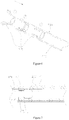
Figure 1 is a schematic diagram of showing the use of one embodiment of the present disclosure in the human body; -
Figure 2 is a schematic diagram of the structure of an interventional medical system according to one embodiment of the present disclosure; -
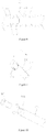
Figure 3 is a schematic diagram of the structure of a plug head portion of an interventional medical device of the interventional medical system inFigure 2 ; -
Figure 4 is a schematic diagram from another view of the plug head portion of the interventional medical device of the interventional medical system inFigure 2 ; -
Figure 5 is a schematic diagram of the structure of a cable portion of a delivery cable of the interventional medical device inFigure 2 ; -
Figure 6 is a schematic diagram of a state of the delivery cable of the interventional medical system inFigure 2 gradually entering a locking sleeve; -
Figure 7 is a schematic diagram of a locking state of the interventional medical system inFigure 2 ; -
Figure 8 is a schematic diagram of part of a profile of the interventional medical system inFigure 2 after a limiting part is added in the interventional medical system; -
Figure 9 is a schematic diagram of the interventional medical system inFigure 2 after a connection between the interventional medical device and the delivery cable in the interventional medical system is partially released; -
Figure 10 is a schematic diagram of the interventional medical system inFigure 2 after the connection between the interventional medical device and the delivery cable in the interventional medical system is completely released; -
Figure 11 is a schematic diagram of an interventional medical system provided by another embodiment of the present disclosure; -
Figure 12 is a schematic diagram of a plug head portion of an interventional medical device of the interventional medical system inFigure 11 ; -
Figure 13 is a schematic diagram from another view of the plug head portion of the interventional medical device of the interventional medical system inFigure 11 ; -
Figure 14 is a schematic diagram of a locking sleeve of the interventional medical system inFigure 11 ; -
Figure 15 is a schematic diagram of an interventional medical system provided by another embodiment of the present disclosure; -
Figure 16 is an exploded schematic diagram of an interventional medical system provided by another embodiment of the present disclosure; -
Figure 17 is a side view of the interventional medical system inFigure 16 ; -
Figure 18 is a combination schematic diagram of the interventional medical system inFigure 16 ; -
Figure 19 is an exploded schematic diagram of an interventional medical system provided by another embodiment of the present disclosure; -
Figure 20 is a side view of the interventional medical system inFigure 19 ; -
Figure 21 is a schematic diagram of a plug head portion of the interventional medical device of the interventional medical system inFigure 19 . - For the purpose of making the objectives, features and advantages of the present disclosure clearer, a detailed description to specific implementation modes of the present disclosure will be made below together with corresponding drawings. Many specific details are described in the following descriptions to facilitate a full understanding of the present disclosure. But the present disclosure may be implemented in many other ways different from those described herein. Persons skilled in the art can make similar improvements without departing from the scope of the present disclosure, so that the present disclosure will not be limited by specific embodiments disclosed below.
- It should be noted that when one element is being "fixed" on another element, it may be directly on another element or an intermediate element also may exist. When one element is deemed as being "connected to" another element, it may be directly connected to another element or an intermediate element may exist at the same time. In the interventional field, generally, the end close to an operator is a proximal end, and the end far away from the operator is a distal end.
- It also should be noted that an interventional medical device in this implementation mode includes a medical device main body portion and a plug head portion connected with the medical device main body portion. The medical device main body portion is a portion of the interventional medical device, which is used for a medical procedure, and the plug head portion is a portion of the interventional medical device, which is connected with a delivery cable.
- Unless otherwise specified, all technical and scientific terms used herein are the same as meanings of general understandings of technical persons skilled in the art of the present disclosure. The terms used in the description of the present disclosure in this text are only to describe specific embodiments, but not intended to limit the present disclosure. The terms "and/or" used in this text include any and all combinations of one or multiple relevant listed items.
- An implementation mode of the present disclosure is applied to interventional medical equipment. As shown in
Figure 1 , this medical equipment includes an interventionalmedical system 10. The interventionalmedical system 10 includes an interventionalmedical device 110, and adelivery cable 200 for delivering the interventionalmedical device 110. Generally, after being connected with the distal end 210 of thedelivery cable 200, the interventionalmedical device 110 is placed in acatheter 201, and is delivered in atissue cavity 101 of a patient, and then a connection between thedelivery cable 200 and the interventionalmedical device 110 is cut off when the interventionalmedical device 110 moves to a selected position, so that the interventionalmedical device 110 is placed at the selected position to implement the interventional therapy. Thetissue cavity 101 may be a cavity formed by atissue wall 102. For example, thetissue cavity 101 includes a blood vessel cavity, an enteric cavity, a heart chamber and a trachea. Of course, thetissue cavity 101 may also include internal tissue cavities in the human body where the device may arrive at during the interventional therapy at the present time, and any one of internal tissue cavities in the human body where the device will arrive at during the interventional therapy in the future. The interventionalmedical device 110 mentioned in this text may be any one medical device for the interventional therapy, such as a heart defect occluder, a valve repair device, a vascular plug, a vascular filter and a lung volume reduction device. Thedelivery cable 200 is a long and thin object for the interventional treatment, such as a steel cable and a catheter, and its distal end is connected with the interventionalmedical device 110. The distal end herein is the end farthest from the operator inFigure 1 , and the relatively proximal end is the end closest to the operator. - Of course, to enable medical staff to clearly know whether the interventional
medical device 110 is delivered to the selected position or not, the medical equipment further may also include a camera apparatus, a monitor and the like. The camera apparatus is placed in thecatheter 201, and shoots video data of thetissue cavity 101 along with the distal end of thecatheter 201; and then the video data are transmitted to the monitor to display corresponding images on aninterface 103, thereby providing precise positioning data of the interventional therapy for the medical staff. - To avoid the difficulties in releasing the interventional
medical device 110 at the correct selected position so that a medical risk factor increases due to the problem in connection between the interventionalmedical device 110 and thedelivery cable 200, in the embodiments of the present disclosure, an improvement is made to an interventionalmedical system 10. The specific improvement is described below together with the drawings. - One embodiment of the present disclosure provides an interventional
medical system 10 for interventional therapy. - With reference also to
Figure 2 , the interventionalmedical system 10 includes an interventionalmedical device 110 and adelivery apparatus 500. Thedevice 110 includes aplug head portion 120 positioned on the interventionalmedical device 110. Thedelivery apparatus 500 includes adelivery cable 200 and a lockingsleeve 300 which surrounds thedelivery cable 200 and may move relative to an axial direction of thedelivery cable 200. Thedelivery cable 200 includes acable head portion 211 which may be radially compressed and may expand to a natural state by itself after an external force is withdrawn. - With reference also to
Figure 3 and Figure 4 , theplug head portion 120 includes a hollowmain body section 121 and at least twofirst locking pieces 123 distributed along a circumferential direction of themain body section 121 in a spaced-apart manner. Afirst locking slot 125 is formed between two adjacentfirst locking pieces 123 in the circumferential direction of theplug head portion 120. Eachfirst locking slot 125 extends through the proximal end surface of theplug head portion 120, and the length of the proximal end of thefirst locking slot 125 in the circumferential direction of theplug head portion 120 is less than that of the distal end of thefirst locking slot 125 in the circumferential direction of theplug head portion 120. - In this embodiment, there are two
first locking pieces 123, and the twofirst locking pieces 123 are arranged on the proximal end surface of themain body section 121; eachfirst locking piece 123 is a T-shaped piece, and the length of its distal end along the circumferential direction of theplug head portion 120 is the maximum length of thefirst locking piece 123 along the circumferential direction of theplug head portion 120. Therefore, in the circumferential direction of theplug head portion 120, two T-shaped first lockingslots 125 are formed between twofirst locking pieces 123. Preferably, in this embodiment, themain body section 121 and the twofirst locking pieces 123 are of an integrated structure formed by cutting one hollow nickel-titanium tube. It can be understood that themain body section 121 and the two lockingpieces 123 also may be made of common metal materials for interventional medical devices, such as stainless steel or a cobalt-chromium alloy. It also can be understood that the twofirst locking pieces 123 also may achieve the same effect by adopting other machining modes, such as linear cutting, powder metallurgy and casting. It can be understood that thefirst locking slots 125 also may be L-shaped, C-shaped or in other shapes, and its shape may be designed as required. - With reference also to
Figure 5 , thecable head portion 211 of thedelivery cable 200 includes ahollow cable section 213 and at least two elasticsecond locking pieces 215 distributed along the circumferential direction of thecable section 213 in a spaced-apart manner. The at least twosecond locking pieces 215 may convert between a compressed state and an expanded state, in other words, eachsecond locking piece 215 may be radially shrunk (namely in the compressed state) under the action of an external force; and after the external force is withdrawn, eachsecond locking piece 215 may be restored to a natural state (namely the expanded state). The thickness of eachsecond locking piece 215 is uniform and consistent, and eachsecond locking piece 215 extends approximately away from the central axial line of thecable head portion 211. In this present disclosure, the situation that eachsecond locking piece 215 extends approximately away from the central axial line of thecable head portion 211 means that when eachsecond locking piece 215 extends approximately away from the central axial line of thecable head portion 211, some portions of eachsecond locking piece 215 are allowed to get close to the central axial line of thecable head portion 211 compared with their adjacent portions; and under radial restriction applied by the lockingsleeve 300, eachsecond locking piece 215 may be at least partially contained in eachfirst locking slot 125 to integrally connect the interventionalmedical device 110 with thedelivery cable 200. - When the at least two
second locking pieces 215 are in a compressed state, onesecond locking slot 217 is formed between two adjacentsecond locking pieces 215 in the circumferential direction of thecable head portion 211. Eachsecond locking slot 217 penetrates through the distal end surface of thecable head portion 211. - In this embodiment, there are two
second locking pieces 215, and the twosecond locking pieces 215 are arranged on the distal end surface of thecable section 213; eachsecond locking piece 215 is a T-shaped piece, and the length of its distal end along the circumferential direction of thecable portion 211 is the maximum length of thesecond locking piece 215 along the circumferential direction of thecable section 211. Therefore, when the twosecond locking pieces 215 are in a compressed state, in the circumferential direction of thecable section 211, two T-shaped second lockingslots 217 are formed between the twosecond locking pieces 215. Preferably, in this embodiment, thecable section 213 and the twosecond locking pieces 215 are of an integrated structure formed by cutting one hollow nickel-titanium tube and then carrying out thermal shaping on the cut tube; when the twosecond locking pieces 215 are in a compressed state, the outer diameter of a whole formed by the twosecond locking pieces 215 is equal to that of thecable section 213. It can be understood that thesecond locking pieces 215 and thecable section 213 also may be separately and independently formed, and then are connected into a whole in a connection by way of welding, adhesion, screwing and the like. It also can be understood that thesecond locking pieces 215 also may be made of other metal materials with relatively good elasticity, such as a cobalt-chromium alloy. - It can be understood that the first locking slots also may be in other shapes such as a cross shape and an I shape, and then the length of the proximal end of each first locking slot in the circumferential direction of the plug head portion is greater than or equal to that of the distal end of a first locking slot in the circumferential direction of the plug head portion; each second locking piece which matches with each first locking slot in shape may still be contained in one corresponding first locking slot under the radial restriction applied by the locking sleeve to connect the plug head portion with the cable head portion.
- With reference also to
Figure 6 , the lockingsleeve 300 is a hollow tubular body, which surrounds the outside of thedelivery cable 200 and may move relative to the axial direction of thedelivery cable 200. When moving relative to the axial direction of the lockingsleeve 300, the twosecond locking pieces 215 of thedelivery cable 200 are radially restrained by the lockingsleeve 300, and may be limited from an expanded state (a state 1 as shown inFigure 6 ) into a cylindrical state (namely the compressed state which is astate 3 as shown inFigure 6 ). In this embodiment, the inner diameter of the lockingsleeve 300 is slightly greater than the outer diameter of thecable section 213 to ensure that the two lockingpieces 215 may be clamped into thefirst locking slots 125 after being completely compressed. - With reference to
Figure 8 , thedelivery apparatus 500 of the interventionalmedical system 10 also includes a cylindrical limitingpart 400. The limitingpart 400 is contained in thedelivery cable 200, and is used for supporting thesecond locking pieces 215. When the interventionalmedical system 10 is in a locked state, the distal end of the limitingpart 400 extends through the distal end of thecable portion 211, and cooperates with the lockingsleeve 300 to clamp thesecond locking pieces 215 between the outer wall of the limitingpart 400 and the inner wall of the lockingsleeve 300 to prevent looseness between thedevice 110 and thedelivery cable 200, which is caused by misalignment between thesecond locking pieces 215 and thefirst locking slots 125 due to a rare circumstance that thesecond locking pieces 215 deform too much towards a direction close to the longitudinal central axis of thecable portion 211. Preferably, in this embodiment, a unilateral gap between thedelivery cable 200 and the limitingpart 400 is less than the wall thickness of thecable section 213, and the limitingpart 400 may move relative to thedelivery cable 200. In other implementation modes of the present disclosure, the limitingpart 400 may be omitted. In other implementation modes of the present disclosure, the limitingpart 400 also may be fixed with thedelivery cable 200 to form a whole. - With reference together to
Figure 8, Figure 10 andFigure 11 , when the interventionalmedical system 10 is in a locked state, namely when theplug head portion 120 is connected with thecable head portion 211, the twosecond locking pieces 215 are radially restrained by the lockingsleeve 300 such that they are limited from an expanded state into a cylindrical state (namely a compressed state), and are clamped into thefirst locking slots 125. As the length of the distal end of eachsecond locking piece 215 along the circumferential direction of thecable head portion 211 is greater than that of the proximal end of thesecond locking piece 215 along the circumferential direction of thecable head portion 211, connection is formed between thedevice 110 and thedelivery cable 200, wherein thedevice 110 and thedelivery cable 200 may not relatively move in both the axial direction and the circumferential direction; when the lockingsleeve 300 moves relative to thedelivery cable 200 towards a direction away from thedevice 110 until thesecond locking pieces 215 elastically move away from thefirst locking slots 125, thedevice 110 is separated from thedelivery cable 200. Therefore, a releasing process of thedevice 110 is as follows: in a locked state, thedelivery cable 200 is stationary, and the lockingsleeve 300 is moved along an arrow direction (namely the direction away from the device 110) as shown inFigure 9 ; thesecond locking pieces 215 having elasticity are gradually withdrawn from the restriction of the lockingsleeve 300 to restore preset horn shapes such that thesecond locking pieces 215 elastically move away from thefirst locking slots 125 gradually; and when thesecond locking pieces 215 have completely and elastically moved away from thefirst locking slots 125, thedevice 110 is separated from the delivery cable 200 (as shown inFigure 10 ), thus fulfilling the objective of releasing thedevice 110. - According to the interventional medical device 100 of this embodiment, when the
plug head portion 120 is connected with thecable head portion 211, onesecond locking piece 215 is clamped into onefirst locking slot 125 under the radial restriction applied by the lockingsleeve 300; and when the lockingsleeve 300 moves relative to thedelivery cable 200 towards the direction away from thedevice 110 until thesecond locking pieces 215 elastically move away from thefirst locking slots 125, thedevice 110 is separated from thedelivery cable 200, thereby completely avoiding a threaded connection for thedevice 110 and the delivery cable, guaranteeing normal release of thedevice 110, and reducing the medical risk. In addition, during the releasing process, it only necessary for the lockingsleeve 300 to move relative to thedelivery cable 200 towards the direction away from thedevice 110 until thesecond locking pieces 215 elastically move away from thefirst locking slots 125; and the operation process is relatively simple, thus shortening the surgery time and reducing the surgery risk for a patient. - It can be understood that in other embodiments there may be one
second locking piece 215 or onefirst locking slot 125 as long as thesecond locking piece 215 may be at least partially contained in thefirst locking slot 125 under the radial restriction applied by the lockingsleeve 300 to connect the interventionalmedical device 110 with thedelivery cable 200. It also may be understood that in other embodiments, under the radial restriction applied by the lockingsleeve 300, eachfirst locking slot 125 also may contain two or moresecond locking pieces 215 as long as the interventionalmedical device 110 is connected with thedelivery cable 200. For example, two or moresecond locking pieces 215 abut the slot wall of onefirst locking slot 125 or are clamped in onefirst locking slot 125. - With reference to
Figure 11 , an interventionalmedical system 10a provided by another embodiment of the present disclosure is approximately the same as the interventionalmedical system 10, and includes an interventional medical device 110a, adelivery cable 200a, and alocking sleeve 300a which surrounds thedelivery cable 200a and may move relative to an axial direction of thedelivery cable 200a. - With reference to
Figure 12 and Figure 13 , aplug head portion 120a of the device 110a is approximately the same as theplug head portion 120, and also includes a hollowmain body section 121a and at least twofirst locking pieces 123a distributed along a circumferential direction of themain body section 121a in a spaced-apart manner; and in the circumferential direction of theplug head portion 120a, onefirst locking slot 125a is formed between two adjacentfirst locking pieces 123a, but the difference is that the outer surfaces of thefirst locking pieces 123a are curved surfaces, and the outer diameter formed by all of the at least twofirst locking pieces 123a is greater than that of themain body section 121a to prevent the proximal end of the device 110a from scratching a human body tissue during the process of implanting the device 110a into a human body. In this embodiment, themain body section 121a and thefirst locking pieces 123a are independently formed, and then are fixedly connected by welding. It can be understood that themain body section 121a and thefirst locking pieces 123a also may be fixedly connected through other connection methods such as adhesion and screwing. Preferably, theplug head portion 120a may be integrated; for example, theplug head portion 120a is made in one piece by adopting turning, milling, drilling, grinding and other machining modes; and for another example, theplug head portion 120a may be formed by adopting other forming modes (such as powder metallurgy and casting). - The
delivery cable 200a is the same as thedelivery cable 200, so no additional details will be described here. - With reference also to
Figure 14 , the lockingsleeve 300a is approximately the same as the lockingsleeve 300, but the difference is that part of the end surface of the distal end of the lockingsleeve 300a is sunken towards the proximal end of the lockingsleeve 300a to form at least two U-shaped containinggrooves 301a distributed in a spaced-apart manner. The containinggrooves 301a are used for containing thefirst locking pieces 123a when the lockingsleeve 300a restrains the second locking pieces of thedelivery cable 200a, thereby reducing the outer diameter of the lockingsleeve 300a. - With reference to
Figure 15 , an interventionalmedical system 10b provided by another embodiment of the present disclosure is approximately the same as the interventionalmedical system 10, and includes an interventionalmedical device 110b, a delivery cable 200b, and a locking sleeve (not shown in the figure) which surrounds the delivery cable and may move relative to an axial direction of the delivery cable 200b. - A
plug head portion 120b of thedevice 110b includes a main body section 121b and aconnection section 123b connected with the main body section 121b. In this embodiment, the main body section 121b and theconnection section 123b are both hollow columnar bodies. It can be understood that in other embodiments, theconnection section 123b also may be a solid columnar body. - The structure of the delivery cable 200b is approximately the same as that of the
delivery cable 200, but the difference is that the inner surfaces ofsecond locking pieces 215b of the delivery cable 200b are roughened to increase the friction force between theconnection section 123b and thesecond locking pieces 215b. - The locking sleeve is approximately the same as the locking
sleeve 300, but the difference is that the thickness and the size of the locking sleeve 300b may be different from those of the lockingsleeve 300 based on the clinical requirements, and no additional details will be described here. - When the locking sleeve radially restrains the
second locking pieces 215b of the delivery cable 200b to the side wall of theconnection section 123b of theplug head portion 120b (namely when thesecond locking pieces 215b form a limiting slot for containing theconnection section 123b in an encircling manner under radial restriction applied by the locking sleeve), a radial pressure is caused between thesecond locking pieces 215b and the side wall of theconnection section 123b, so that a friction force for preventing relative movement between the delivery cable 200b and thedevice 110b is generated between thesecond locking pieces 215b and theconnection section 123b, and the connection between the delivery cable 200b and thedevice 110b will be achieved. - It can be understood that the side wall of the
connection section 123b may also be roughened to enhance the friction force between thesecond locking pieces 215b and theconnection section 123b. It also can be understood that friction force enhancing pieces, such as rubber and sponge, for increasing the friction force, may also be arranged on theconnection section 123b and/or thesecond locking pieces 215b. - It can be understood that in other embodiments, there may be one
second locking piece 215b as long as under the radial restriction applied by the locking sleeve, the inner surface, which is close to the longitudinal central axis of the delivery cable 200b, of thesecond locking piece 215b may abut the side wall of theconnection section 123b to connect the interventionalmedical device 110b with the delivery cable 200b. - With reference to
Figures 16 ,17 and 18 , an interventional medical system 10c provided by another embodiment of the present disclosure is approximately the same as the interventionalmedical system 10b, and includes an interventional medical device having aplug head portion 120c, a delivery cable 200c, and a lockingsleeve 300c which surrounds the delivery cable 200c and may move relative to an axial direction of the delivery cable 200c. - The
plug head portion 120c is approximately the same as theplug head portion 120b, but the difference is that theplug head portion 120c includes asolid connection section 123c, and first lockingslots 125c are formed in the side wall of theconnection section 123c. It can be understood that in other embodiments theconnection section 123c also may be of a hollow structure, and at the moment, thefirst locking slots 125c may be separated from a tubular cavity of theconnection section 123c; in other words, thefirst locking slots 125c do not penetrate through the inner wall of theconnection section 123c. - The delivery cable 200c is approximately the same as the delivery cable 200b, and includes
second locking pieces 215c which extend approximately away from the central axial line of a cable head portion 211c and has uniform thicknesses. But the difference is that the distal end sections 216c of thesecond locking pieces 215c are slightly closer to the central axial line of the cable head portion 211c than their adjacent sections, so that the distal end sections 216c of thesecond locking pieces 215c may better enter thefirst locking slots 125c to achieve the connection between theplug head portion 120c and the delivery cable 200c. - The locking
sleeve 300c is approximately the same as the locking sleeve 300b, but the difference is that the thickness and the size of the lockingsleeve 300c may be different from those of the locking sleeve 300b according to clinical requirements, and no additional details will be described here. - When the locking
sleeve 300c radially restrains thesecond locking pieces 215c of the delivery cable 200c to the side wall of theconnection section 123c of theplug head portion 120c (namely when thesecond locking pieces 215c form a limiting slot for containing theconnection section 123c in an encircling manner under radial restriction applied by the lockingsleeve 300c), the distal end sections 216c of thesecond locking pieces 215c are locked into thefirst locking slots 125c to achieve the connection between the delivery cable 200c and the interventional medical device having theplug head portion 120c. - It can be understood that in other embodiments, there may be one
second locking piece 215c or onefirst locking slot 125c as long as thesecond locking pieces 215 may abut the wall of theconnection section 123c to connect the interventional medical device 110c with the delivery cable 200c under the radial restriction applied by the lockingsleeve 300c. It also can be understood that in other embodiments, under the radial restriction applied by the lockingsleeve 300c, eachfirst locking slot 125c may also contain two or moresecond locking pieces 215c as long as the interventional medical device 110c is connected with the delivery cable 200c. For example, two or moresecond locking pieces 215c abut the slot wall of onefirst locking slot 125c or are clamped in onefirst locking slot 125c. - With reference to
Figure 19 andFigure 20 , an interventionalmedical system 10d provided by another embodiment of the present disclosure includes an interventional medical device having aplug head portion 120d, adelivery cable 200d, and alocking sleeve 300d which surrounds thedelivery cable 200d and may move relative to an axial direction of thedelivery cable 200d. - The
plug head portion 120d is approximately the same as theplug head portion 120b, and includes ahollow connection section 123d. But the difference is that T-shaped first lockingslots 125d are formed in the side wall of theconnection section 123d, and are separated from the tubular cavity of theconnection section 123d, and the proximal ends of thefirst locking slots 125d penetrate through the proximal end surface of theconnection section 123d. It can be understood that in other embodiments, theconnection section 123d also may be of a solid structure. It can be understood that thefirst locking slots 125d may also be L-shaped locking slots, C-shaped locking slots or locking slots in other shapes, and not limited to the T-shaped locking slots in this embodiment. - The
delivery cable 200d is approximately the same as thedelivery cable 200, but the difference is that the thicknesses and the sizes of all elements of thedelivery cable 200d may be different from those of all corresponding elements of thedelivery cable 200 according to clinical requirements as long as the thicknesses of the locking pieces of thedelivery cable 200d are uniform, and no additional details will be described here. - The locking
sleeve 300d is approximately the same as the lockingsleeve 300, but the difference is that the thickness and the size of the lockingsleeve 300d may be different from those of the lockingsleeve 300 according to the clinical requirements, and no additional details will be described here. - When the locking
sleeve 300d radially restrains the second locking pieces 215d of thedelivery cable 200d to the side wall of theconnection section 123d of theplug head portion 120d (namely when the second locking pieces 215d form a limiting slot for containing theconnection section 123d in an encircling manner under radial restriction applied by the lockingsleeve 300d), the second locking pieces 215d are at least partially locked into thefirst locking slots 125d to achieve the connection between thedelivery cable 200d and the interventional medical device. - It can be understood that in other embodiments, there also may be one second locking piece 215d or one
first locking slot 125d as long as the second locking pieces 215d may abut theconnection section 123d to connect the interventional medical device with thedelivery cable 200d under the radial restriction applied by the lockingsleeve 300d. It also can be understood that in other embodiments, under the radial restriction applied by the lockingsleeve 300d, eachfirst locking slot 125d also may contain two or more second locking pieces 215d as long as the interventional medical device is connected with thedelivery cable 200d, for example, two or more second locking pieces 215d abut the slot wall of onefirst locking slot 125d or are clamped in onefirst locking slot 125d. - All technical features of the above-mentioned embodiments may be randomly combined. To make their descriptions simple, not all possible combinations of all the technical features in the above-mentioned embodiments are described, but the combinations of these technical features shall all be deemed as the scope of this description in case of no contradictions.
- The above-mentioned embodiments are only expressive of several implementation modes of the present disclosure, and their descriptions are relatively specific and detailed, but may not be understood as limitations to the scope of the patent for invention. It should be noted that ordinary persons skilled in the art can further make a plurality of deformations and improvements that all fall within the scope of protection of the present disclosure without departing from the concept of the present disclosure. Therefore, the scope of protection of the patent for invention shall be based on attached claims.
Claims (30)
- An interventional medical system, comprising a device provided with a plug head portion and a delivery cable provided with a cable head portion, characterized in that the interventional medical system further comprises a locking sleeve movably surrounding the outside of the delivery cable; the cable head portion comprises at least one elastic locking piece which extends approximately away from the central axial line of the cable head portion; under radial restriction applied by the locking sleeve, the plug head portion abuts the locking piece such that the plug head portion is connected with the cable head portion, and when the locking sleeve moves relative to the delivery cable to a position where the locking piece is no longer radially restrained, the locking piece elastically moves away from the plug head portion such that the device is separated from the delivery cable.
- The interventional medical system according to claim 1, characterized in that the cable head portion comprises multiple locking pieces; the multiple locking pieces of the cable head portion form a limiting slot in an encircling manner; and under radial restriction applied by the locking sleeve, the plug head portion is contained in the limiting slot, so that the plug head portion is connected with the cable head portion.
- The interventional medical system according to claim 1, characterized in that at least one locking slot is formed in the side wall of the plug head portion; and when the plug head portion is connected with the cable head portion, at least one locking piece of the cable head portion is at least contained in the locking slot of the plug head portion.
- The interventional medical system according to claim 3, characterized in that the locking slot of the plug head portion extends along an axial direction of the plug head portion, and penetrates through the proximal end surface of the plug head portion.
- An interventional medical system, comprising a device provided with a plug head portion and a delivery cable provided with a cable head portion, characterized in that the interventional medical system further comprises a locking sleeve movably surrounding the outside of the delivery cable; the plug head portion comprises at least one locking slot which penetrates through the proximal end surface of the plug head portion; the cable head portion comprises at least one elastic locking piece which extends approximately away from the central axial line of the cable head portion; under radial restriction applied by the locking sleeve, at least one locking piece of the cable head portion is contained in each locking slot of the plug head portion such that the plug head portion is connected with the cable head portion, and when the locking sleeve moves relative to the delivery cable to a position where the locking pieces of the cable head portion are no longer radially restrained, the locking pieces of the cable head portion elastically move away from the locking slots of the plug head portion such that the device is separated from the delivery cable.
- The interventional medical system according to claim 5, characterized in that the plug head portion comprises multiple mutually separated locking pieces; each locking slot of the plug head portion is positioned between two adjacent locking pieces of the plug head portion; and under radial restriction applied by the locking sleeve, each locking piece of the cable head portion is contained in one locking slot of the plug head portion such that the plug head portion is connected with the cable head portion.
- The interventional medical system according to any one of claims 3 to 6, characterized in that the length of the proximal end of each locking slot of the plug head portion in a circumferential direction of the plug head portion is less than that of the distal end of the locking slot of the plug head portion in the circumferential direction of the plug head portion.
- The interventional medical system according to claim 7, characterized in that the locking slot of the plug head portion comprises a T-shaped structure having a distal end, and the length of the distal end of the T-shaped structure in the circumferential direction of the plug head portion is the maximum length of the T-shaped structure in the circumferential direction of the plug head portion.
- The interventional medical system according to any one of claims 3 to 6, characterized in that the interventional medical system further comprises a limiting part contained in the delivery cable; and when the plug head portion is connected with the cable head portion, the locking pieces of the cable head portion are also clamped between the limiting part and the locking sleeve.
- The interventional medical system according to claim 9, characterized in that the delivery cable comprises a hollow cable section having a distal end; the locking pieces of the cable head portion are arranged at the distal end of the cable section; and a unilateral gap between the delivery cable and the limiting part is less than the wall thickness of the cable section.
- The interventional medical system according to claims 3 to 6, characterized in that the thicknesses of the locking pieces of the cable head portion are uniform.
- The interventional medical system according to claim 6, characterized in that each locking slot has a proximal end and an distal end, and the length of the proximal end of each locking slot of the plug head portion in the circumferential direction of the plug head portion is less than that of the distal end of the locking slot of the plug head portion in the circumferential direction of the plug head portion, and the length of the proximal end of each locking piece of the plug head portion along the circumferential direction of the plug head portion is greater than that of the distal end of the locking piece of the plug head portion along the circumferential direction of the plug head portion.
- The interventional medical system according to claim 12, characterized in that the plug head portion comprises a hollow main body section having a proximal end surface, and the locking pieces of the plug head portion are arranged on the proximal end surface of the hollow main body section.
- The interventional medical system according to claim 13, characterized in that the main body section and the locking pieces of the plug head portion are of an integrated structure formed by cutting one hollow tube.
- The interventional medical system according to claim 13, characterized in that the outer surfaces of the locking pieces of the plug head portion are curved surfaces, and the outer diameter of a whole formed by the locking pieces of the plug head portion is greater than that of the main body section; part of the end surface of the distal end of the locking sleeve is sunken towards the proximal end of the locking sleeve to form at least one containing groove; and when the locking sleeve radially restrains the locking pieces of the cable head portion, the locking pieces of the plug head portion are at least partially contained in the containing grooves.
- An interventional medical device, comprising a plug head portion positioned at the proximal end of the interventional medical device, characterized in that at least one locking slot is formed in the side wall of the plug head portion.
- The interventional medical device according to claim 16, characterized in that the locking slots of the plug head portion extend along an axial direction of the plug head portion, and penetrate through the proximal end surface of the plug head portion.
- An interventional medical device, comprising a plug head portion positioned at the proximal end of the interventional medical device, characterized in that the plug head portion comprises at least one locking slot which penetrates through the proximal end surface of the plug head portion.
- The interventional medical device according to any one of claims 16 to 18, characterized in that each locking slot has a proximal end and an distal end, and the length of the proximal end of each locking slot along a circumferential direction of the plug head portion is less than that of the distal end of the locking slot along the circumferential direction of the plug head portion.
- The interventional medical device according to any one of claims 16 to 18, characterized in that each locking slot comprises a T-shaped structure having a distal end; and the length of the distal end of the T-shaped structure in the circumferential direction of the plug head portion is the maximum length of the T-shaped structure in the circumferential direction of the plug head portion.
- The interventional medical device according to claim 18, characterized in that the locking piece is a T-shaped piece and has a proximal end, and the length of the proximal end of the locking piece along the circumferential direction of the plug head portion is the maximum length of the locking piece along the circumferential direction of the plug head portion.
- The interventional medical device according to claim 18, characterized in that the plug head portion comprises a hollow main body section having a proximal surface; the plug head portion comprises multiple mutually separated locking pieces; each locking slot of the plug head portion is positioned between two adjacent locking pieces of the plug head portion; and the locking pieces of the plug head portion are arranged on the proximal end surface of the hollow main body section.
- The interventional medical device according to claim 22, characterized in that the main body section and the locking pieces are of an integrated structure formed by cutting one hollow tube.
- The interventional medical device according to claim 22, characterized in that the outer surfaces of the locking pieces are curved surfaces, and the outer diameter of a whole formed by the locking pieces of the plug head portion is greater than that of the main body section.
- A delivery apparatus of an interventional medical device, comprising a delivery cable which comprises a cable head portion detachably connected with the interventional medical device, characterized in that the delivery apparatus further comprises a locking sleeve movably surrounding the outside of the delivery cable; the cable head portion comprises at least one elastic locking piece which extends approximately away from the central axial line of the cable head portion; the locking piece is compressed under radial restriction applied by the locking sleeve, and restores when the locking sleeve moves relative to the delivery cable to a position where the locking piece is no longer radially restrained.
- The delivery apparatus according to claim 25, characterized in that the cable head portion comprises multiple mutually separated locking pieces.
- The delivery apparatus according to claim 25, characterized in that each locking piece is a T-shaped piece and has a distal end, and the length of the distal end of each locking piece along a circumferential direction of the cable head portion is the maximum length of the locking piece along the circumferential direction of the cable head portion.
- The delivery apparatus according to any one of claims 25 to 27, characterized in that the thicknesses of the locking pieces are uniform.
- The delivery apparatus according to claim 28, characterized in that the delivery apparatus further comprises a limiting part contained in the delivery cable, and the limiting part cooperates with the locking sleeve to clamp the locking pieces between the limiting part and the locking sleeve.
- The delivery apparatus according to claim 29, characterized in that the delivery cable comprises a hollow cable section having a distal end; the locking pieces are arranged at the distal end of the cable section; and a unilateral gap between the delivery cable and the limiting part is less than the wall thickness of the cable section.
Applications Claiming Priority (2)
| Application Number | Priority Date | Filing Date | Title |
|---|---|---|---|
| CN201511033393.7A CN105640620A (en) | 2015-12-31 | 2015-12-31 | Interventional medical instrument, conveying device and interventional medical system |
| PCT/CN2016/087768 WO2017113667A1 (en) | 2015-12-31 | 2016-06-29 | Interventional medical instrument, delivery apparatus, and interventional medical system |
Publications (3)
| Publication Number | Publication Date |
|---|---|
| EP3398567A1 true EP3398567A1 (en) | 2018-11-07 |
| EP3398567A4 EP3398567A4 (en) | 2019-08-07 |
| EP3398567B1 EP3398567B1 (en) | 2023-12-20 |
Family
ID=56491300
Family Applications (1)
| Application Number | Title | Priority Date | Filing Date |
|---|---|---|---|
| EP16880472.2A Active EP3398567B1 (en) | 2015-12-31 | 2016-06-29 | Interventional medical system |
Country Status (4)
| Country | Link |
|---|---|
| US (1) | US11058852B2 (en) |
| EP (1) | EP3398567B1 (en) |
| CN (1) | CN105640620A (en) |
| WO (1) | WO2017113667A1 (en) |
Families Citing this family (16)
| Publication number | Priority date | Publication date | Assignee | Title |
|---|---|---|---|---|
| AU2015249283B2 (en) | 2014-04-25 | 2019-07-18 | Flow Medtech, Llc | Left atrial appendage occlusion device |
| US10856881B2 (en) | 2014-09-19 | 2020-12-08 | Flow Medtech, Inc. | Left atrial appendage occlusion device delivery system |
| CN105640620A (en) * | 2015-12-31 | 2016-06-08 | 先健科技(深圳)有限公司 | Interventional medical instrument, conveying device and interventional medical system |
| US10576099B2 (en) | 2016-10-21 | 2020-03-03 | Covidien Lp | Injectable scaffold for treatment of intracranial aneurysms and related technology |
| US11110248B2 (en) * | 2016-11-17 | 2021-09-07 | Boston Scientific Scimed, Inc. | Medical device release system |
| CN108261213B (en) * | 2016-12-30 | 2020-10-23 | 先健科技(深圳)有限公司 | Interventional medical systems, delivery devices and implantable medical devices |
| IT201700038786A1 (en) * | 2017-04-07 | 2018-10-07 | Mascia Brunelli S P A | DEVICE FOR CLOSING A TROCAR SITE |
| EP3644902B1 (en) * | 2017-06-30 | 2024-05-22 | Edwards Lifesciences Corporation | Lock and release mechanisms for trans-catheter implantable devices |
| CN108420463B (en) * | 2018-03-20 | 2024-09-06 | 温州市中心医院 | Bone marrow puncture needle for hematology department |
| CN110897763B (en) * | 2018-09-17 | 2022-09-06 | 东莞市先健医疗有限公司 | Medical instrument conveying device |
| WO2021092619A1 (en) | 2019-11-04 | 2021-05-14 | Covidien Lp | Systems and methods for treating aneurysms |
| CN110742710A (en) * | 2019-11-22 | 2020-02-04 | 茵络(无锡)医疗器械有限公司 | Wire locking device |
| CN113693645B (en) * | 2020-05-21 | 2025-11-21 | 上海微创心通医疗科技有限公司 | Handle, catheter assembly and delivery system for delivering implants |
| CN117295458A (en) * | 2021-01-10 | 2023-12-26 | 卢塞德血管有限公司 | intravascular device |
| CN116784920A (en) * | 2022-03-18 | 2023-09-22 | 南微医学科技股份有限公司 | medical device |
| WO2023181048A1 (en) * | 2022-03-21 | 2023-09-28 | Sahajanand Medical Technologies Limited | Implant detachment mechanism |
Family Cites Families (12)
| Publication number | Priority date | Publication date | Assignee | Title |
|---|---|---|---|---|
| US8216256B2 (en) * | 1999-04-09 | 2012-07-10 | Evalve, Inc. | Detachment mechanism for implantable fixation devices |
| EP1326672A4 (en) * | 2000-10-18 | 2007-03-07 | Nmt Medical Inc | Over-the-wire interlock attachment/detachment mechanism |
| EP1531737B1 (en) * | 2002-08-14 | 2008-12-17 | Boston Scientific Limited | Systems and devices relating to delivery of medical implants |
| US7771463B2 (en) | 2003-03-26 | 2010-08-10 | Ton Dai T | Twist-down implant delivery technologies |
| US7678129B1 (en) * | 2004-03-19 | 2010-03-16 | Advanced Cardiovascular Systems, Inc. | Locking component for an embolic filter assembly |
| FR2885794B1 (en) * | 2005-05-19 | 2007-08-17 | Perouse Soc Par Actions Simpli | NECESSARY FOR LANDING A CAVITY TREATMENT BODY AND METHOD FOR PREPARING A TREATMENT BODY THEREFOR |
| US20070135826A1 (en) * | 2005-12-01 | 2007-06-14 | Steve Zaver | Method and apparatus for delivering an implant without bias to a left atrial appendage |
| WO2012065625A1 (en) * | 2010-11-15 | 2012-05-24 | Endovascular Development AB | An assembly with a guide wire and a fixator for attaching to a blood vessel |
| US9572558B2 (en) * | 2012-02-29 | 2017-02-21 | Vivasure Medical Limited | Devices and methods for delivering implants for percutaneous perforation closure |
| GB2514954B (en) | 2012-03-29 | 2016-03-09 | Spiration Inc | Medical devices for manipulating foreign bodies |
| CN205458944U (en) * | 2015-12-31 | 2016-08-17 | 先健科技(深圳)有限公司 | Intervene medical instrument , conveyor and intervene medical system |
| CN105640620A (en) * | 2015-12-31 | 2016-06-08 | 先健科技(深圳)有限公司 | Interventional medical instrument, conveying device and interventional medical system |
-
2015
- 2015-12-31 CN CN201511033393.7A patent/CN105640620A/en active Pending
-
2016
- 2016-06-29 EP EP16880472.2A patent/EP3398567B1/en active Active
- 2016-06-29 WO PCT/CN2016/087768 patent/WO2017113667A1/en not_active Ceased
- 2016-06-29 US US16/066,249 patent/US11058852B2/en active Active
Also Published As
| Publication number | Publication date |
|---|---|
| US20190009057A1 (en) | 2019-01-10 |
| US11058852B2 (en) | 2021-07-13 |
| CN105640620A (en) | 2016-06-08 |
| EP3398567A4 (en) | 2019-08-07 |
| WO2017113667A1 (en) | 2017-07-06 |
| EP3398567B1 (en) | 2023-12-20 |
Similar Documents
| Publication | Publication Date | Title |
|---|---|---|
| US11058852B2 (en) | Interventional medical instrument, delivery apparatus, and interventional medical system | |
| US11793567B2 (en) | Catheter insertion | |
| US10687821B2 (en) | Lung volume reduction elastic implant and lung volume reduction instrument | |
| US9358042B2 (en) | Expandable member for perforation occlusion | |
| US10188497B2 (en) | Implant conveying device and implanted medical instrument | |
| US20150119796A1 (en) | Anti-Lockup Thread Attachment Mechanism and Method of Use Thereof | |
| US10905538B2 (en) | Lung-volume-reduction elastic implant and lung-volume reduction instrument | |
| US12402998B2 (en) | Implantable artificial bronchus and use of an implantable artificial bronchus | |
| US9061115B2 (en) | Methods and apparatus for providing an arteriovenous fistula | |
| CN108472148A (en) | Through catheter insertion system | |
| JP2015221382A (en) | System of treating lung airway | |
| JP2017517339A (en) | Lung volume reduced elastic implants and instruments | |
| US11266415B2 (en) | Lung volume reduction elastic implant and lung volume reduction instrument | |
| CN108261213B (en) | Interventional medical systems, delivery devices and implantable medical devices | |
| CN205458944U (en) | Intervene medical instrument , conveyor and intervene medical system | |
| CN104799894A (en) | a release device | |
| CN204744260U (en) | Release | |
| JP2023528783A (en) | Systems, methods and devices for embolic protection | |
| Takahashi et al. | Virtual 5-French intra-aortic pumping using a Glidesheath Slender and 6-French intra-aortic balloon catheter | |
| Aivazian et al. | TEMPORARY BALLOON OCCLUSION OF SUBCLAVIAN VEIN IN ITS INJURY DURING TRANSVENOUS LEADS EXTRACTION IN PATIENT WITH A SUPERIOR VENA CAVA SYNDROME: CASE REPORT | |
| KR20240022569A (en) | Removable sheath assembly | |
| VEIN et al. | SA Aivazian, IN Sorokin, VA Belskiy Federal Budget Institution of Health Volga reginal medical center Federal Bio-Medical Agency, Russia, Nizhniy Novgorod, 2 Nizhnevolzhskaya emb. | |
| Wong | Congenital Heart Disease-A Review of the Treatment Methods | |
| Seok et al. | Simple stapled division of aberrant artery during thoracoscopic resection of pulmonary sequestration |
Legal Events
| Date | Code | Title | Description |
|---|---|---|---|
| STAA | Information on the status of an ep patent application or granted ep patent |
Free format text: STATUS: THE INTERNATIONAL PUBLICATION HAS BEEN MADE |
|
| PUAI | Public reference made under article 153(3) epc to a published international application that has entered the european phase |
Free format text: ORIGINAL CODE: 0009012 |
|
| STAA | Information on the status of an ep patent application or granted ep patent |
Free format text: STATUS: REQUEST FOR EXAMINATION WAS MADE |
|
| 17P | Request for examination filed |
Effective date: 20180730 |
|
| AK | Designated contracting states |
Kind code of ref document: A1 Designated state(s): AL AT BE BG CH CY CZ DE DK EE ES FI FR GB GR HR HU IE IS IT LI LT LU LV MC MK MT NL NO PL PT RO RS SE SI SK SM TR |
|
| AX | Request for extension of the european patent |
Extension state: BA ME |
|
| DAV | Request for validation of the european patent (deleted) | ||
| DAX | Request for extension of the european patent (deleted) | ||
| A4 | Supplementary search report drawn up and despatched |
Effective date: 20190710 |
|
| RIC1 | Information provided on ipc code assigned before grant |
Ipc: A61F 2/95 20130101AFI20190704BHEP Ipc: A61F 2/966 20130101ALI20190704BHEP Ipc: A61B 17/00 20060101ALI20190704BHEP |
|
| RAP1 | Party data changed (applicant data changed or rights of an application transferred) |
Owner name: SHENZHEN LIFETECH RESPIRATION SCIENTIFIC CO., LTD. |
|
| STAA | Information on the status of an ep patent application or granted ep patent |
Free format text: STATUS: EXAMINATION IS IN PROGRESS |
|
| 17Q | First examination report despatched |
Effective date: 20220727 |
|
| GRAP | Despatch of communication of intention to grant a patent |
Free format text: ORIGINAL CODE: EPIDOSNIGR1 |
|
| STAA | Information on the status of an ep patent application or granted ep patent |
Free format text: STATUS: GRANT OF PATENT IS INTENDED |
|
| INTG | Intention to grant announced |
Effective date: 20230714 |
|
| GRAS | Grant fee paid |
Free format text: ORIGINAL CODE: EPIDOSNIGR3 |
|
| GRAA | (expected) grant |
Free format text: ORIGINAL CODE: 0009210 |
|
| STAA | Information on the status of an ep patent application or granted ep patent |
Free format text: STATUS: THE PATENT HAS BEEN GRANTED |
|
| AK | Designated contracting states |
Kind code of ref document: B1 Designated state(s): AL AT BE BG CH CY CZ DE DK EE ES FI FR GB GR HR HU IE IS IT LI LT LU LV MC MK MT NL NO PL PT RO RS SE SI SK SM TR |
|
| P01 | Opt-out of the competence of the unified patent court (upc) registered |
Effective date: 20231115 |
|
| REG | Reference to a national code |
Ref country code: GB Ref legal event code: FG4D |
|
| REG | Reference to a national code |
Ref country code: DE Ref legal event code: R096 Ref document number: 602016084907 Country of ref document: DE |
|
| REG | Reference to a national code |
Ref country code: CH Ref legal event code: EP |
|
| REG | Reference to a national code |
Ref country code: IE Ref legal event code: FG4D |
|
| PG25 | Lapsed in a contracting state [announced via postgrant information from national office to epo] |
Ref country code: GR Free format text: LAPSE BECAUSE OF FAILURE TO SUBMIT A TRANSLATION OF THE DESCRIPTION OR TO PAY THE FEE WITHIN THE PRESCRIBED TIME-LIMIT Effective date: 20240321 |
|
| REG | Reference to a national code |
Ref country code: LT Ref legal event code: MG9D |
|
| PG25 | Lapsed in a contracting state [announced via postgrant information from national office to epo] |
Ref country code: LT Free format text: LAPSE BECAUSE OF FAILURE TO SUBMIT A TRANSLATION OF THE DESCRIPTION OR TO PAY THE FEE WITHIN THE PRESCRIBED TIME-LIMIT Effective date: 20231220 |
|
| REG | Reference to a national code |
Ref country code: NL Ref legal event code: MP Effective date: 20231220 |
|
| PG25 | Lapsed in a contracting state [announced via postgrant information from national office to epo] |
Ref country code: ES Free format text: LAPSE BECAUSE OF FAILURE TO SUBMIT A TRANSLATION OF THE DESCRIPTION OR TO PAY THE FEE WITHIN THE PRESCRIBED TIME-LIMIT Effective date: 20231220 |
|
| PG25 | Lapsed in a contracting state [announced via postgrant information from national office to epo] |
Ref country code: LT Free format text: LAPSE BECAUSE OF FAILURE TO SUBMIT A TRANSLATION OF THE DESCRIPTION OR TO PAY THE FEE WITHIN THE PRESCRIBED TIME-LIMIT Effective date: 20231220 Ref country code: GR Free format text: LAPSE BECAUSE OF FAILURE TO SUBMIT A TRANSLATION OF THE DESCRIPTION OR TO PAY THE FEE WITHIN THE PRESCRIBED TIME-LIMIT Effective date: 20240321 Ref country code: FI Free format text: LAPSE BECAUSE OF FAILURE TO SUBMIT A TRANSLATION OF THE DESCRIPTION OR TO PAY THE FEE WITHIN THE PRESCRIBED TIME-LIMIT Effective date: 20231220 Ref country code: ES Free format text: LAPSE BECAUSE OF FAILURE TO SUBMIT A TRANSLATION OF THE DESCRIPTION OR TO PAY THE FEE WITHIN THE PRESCRIBED TIME-LIMIT Effective date: 20231220 Ref country code: BG Free format text: LAPSE BECAUSE OF FAILURE TO SUBMIT A TRANSLATION OF THE DESCRIPTION OR TO PAY THE FEE WITHIN THE PRESCRIBED TIME-LIMIT Effective date: 20240320 |
|
| REG | Reference to a national code |
Ref country code: AT Ref legal event code: MK05 Ref document number: 1641849 Country of ref document: AT Kind code of ref document: T Effective date: 20231220 |
|
| PG25 | Lapsed in a contracting state [announced via postgrant information from national office to epo] |
Ref country code: NL Free format text: LAPSE BECAUSE OF FAILURE TO SUBMIT A TRANSLATION OF THE DESCRIPTION OR TO PAY THE FEE WITHIN THE PRESCRIBED TIME-LIMIT Effective date: 20231220 |
|
| PG25 | Lapsed in a contracting state [announced via postgrant information from national office to epo] |
Ref country code: SE Free format text: LAPSE BECAUSE OF FAILURE TO SUBMIT A TRANSLATION OF THE DESCRIPTION OR TO PAY THE FEE WITHIN THE PRESCRIBED TIME-LIMIT Effective date: 20231220 Ref country code: RS Free format text: LAPSE BECAUSE OF FAILURE TO SUBMIT A TRANSLATION OF THE DESCRIPTION OR TO PAY THE FEE WITHIN THE PRESCRIBED TIME-LIMIT Effective date: 20231220 Ref country code: NO Free format text: LAPSE BECAUSE OF FAILURE TO SUBMIT A TRANSLATION OF THE DESCRIPTION OR TO PAY THE FEE WITHIN THE PRESCRIBED TIME-LIMIT Effective date: 20240320 Ref country code: NL Free format text: LAPSE BECAUSE OF FAILURE TO SUBMIT A TRANSLATION OF THE DESCRIPTION OR TO PAY THE FEE WITHIN THE PRESCRIBED TIME-LIMIT Effective date: 20231220 Ref country code: LV Free format text: LAPSE BECAUSE OF FAILURE TO SUBMIT A TRANSLATION OF THE DESCRIPTION OR TO PAY THE FEE WITHIN THE PRESCRIBED TIME-LIMIT Effective date: 20231220 Ref country code: HR Free format text: LAPSE BECAUSE OF FAILURE TO SUBMIT A TRANSLATION OF THE DESCRIPTION OR TO PAY THE FEE WITHIN THE PRESCRIBED TIME-LIMIT Effective date: 20231220 |
|
| PG25 | Lapsed in a contracting state [announced via postgrant information from national office to epo] |
Ref country code: IS Free format text: LAPSE BECAUSE OF FAILURE TO SUBMIT A TRANSLATION OF THE DESCRIPTION OR TO PAY THE FEE WITHIN THE PRESCRIBED TIME-LIMIT Effective date: 20240420 |
|
| PG25 | Lapsed in a contracting state [announced via postgrant information from national office to epo] |
Ref country code: CZ Free format text: LAPSE BECAUSE OF FAILURE TO SUBMIT A TRANSLATION OF THE DESCRIPTION OR TO PAY THE FEE WITHIN THE PRESCRIBED TIME-LIMIT Effective date: 20231220 Ref country code: AT Free format text: LAPSE BECAUSE OF FAILURE TO SUBMIT A TRANSLATION OF THE DESCRIPTION OR TO PAY THE FEE WITHIN THE PRESCRIBED TIME-LIMIT Effective date: 20231220 |
|
| PG25 | Lapsed in a contracting state [announced via postgrant information from national office to epo] |
Ref country code: SK Free format text: LAPSE BECAUSE OF FAILURE TO SUBMIT A TRANSLATION OF THE DESCRIPTION OR TO PAY THE FEE WITHIN THE PRESCRIBED TIME-LIMIT Effective date: 20231220 |
|
| PG25 | Lapsed in a contracting state [announced via postgrant information from national office to epo] |
Ref country code: SM Free format text: LAPSE BECAUSE OF FAILURE TO SUBMIT A TRANSLATION OF THE DESCRIPTION OR TO PAY THE FEE WITHIN THE PRESCRIBED TIME-LIMIT Effective date: 20231220 Ref country code: SK Free format text: LAPSE BECAUSE OF FAILURE TO SUBMIT A TRANSLATION OF THE DESCRIPTION OR TO PAY THE FEE WITHIN THE PRESCRIBED TIME-LIMIT Effective date: 20231220 Ref country code: RO Free format text: LAPSE BECAUSE OF FAILURE TO SUBMIT A TRANSLATION OF THE DESCRIPTION OR TO PAY THE FEE WITHIN THE PRESCRIBED TIME-LIMIT Effective date: 20231220 Ref country code: IT Free format text: LAPSE BECAUSE OF FAILURE TO SUBMIT A TRANSLATION OF THE DESCRIPTION OR TO PAY THE FEE WITHIN THE PRESCRIBED TIME-LIMIT Effective date: 20231220 Ref country code: IS Free format text: LAPSE BECAUSE OF FAILURE TO SUBMIT A TRANSLATION OF THE DESCRIPTION OR TO PAY THE FEE WITHIN THE PRESCRIBED TIME-LIMIT Effective date: 20240420 Ref country code: EE Free format text: LAPSE BECAUSE OF FAILURE TO SUBMIT A TRANSLATION OF THE DESCRIPTION OR TO PAY THE FEE WITHIN THE PRESCRIBED TIME-LIMIT Effective date: 20231220 Ref country code: CZ Free format text: LAPSE BECAUSE OF FAILURE TO SUBMIT A TRANSLATION OF THE DESCRIPTION OR TO PAY THE FEE WITHIN THE PRESCRIBED TIME-LIMIT Effective date: 20231220 Ref country code: AT Free format text: LAPSE BECAUSE OF FAILURE TO SUBMIT A TRANSLATION OF THE DESCRIPTION OR TO PAY THE FEE WITHIN THE PRESCRIBED TIME-LIMIT Effective date: 20231220 |
|
| PG25 | Lapsed in a contracting state [announced via postgrant information from national office to epo] |
Ref country code: PL Free format text: LAPSE BECAUSE OF FAILURE TO SUBMIT A TRANSLATION OF THE DESCRIPTION OR TO PAY THE FEE WITHIN THE PRESCRIBED TIME-LIMIT Effective date: 20231220 Ref country code: PT Free format text: LAPSE BECAUSE OF FAILURE TO SUBMIT A TRANSLATION OF THE DESCRIPTION OR TO PAY THE FEE WITHIN THE PRESCRIBED TIME-LIMIT Effective date: 20240422 |
|
| PG25 | Lapsed in a contracting state [announced via postgrant information from national office to epo] |
Ref country code: PT Free format text: LAPSE BECAUSE OF FAILURE TO SUBMIT A TRANSLATION OF THE DESCRIPTION OR TO PAY THE FEE WITHIN THE PRESCRIBED TIME-LIMIT Effective date: 20240422 Ref country code: PL Free format text: LAPSE BECAUSE OF FAILURE TO SUBMIT A TRANSLATION OF THE DESCRIPTION OR TO PAY THE FEE WITHIN THE PRESCRIBED TIME-LIMIT Effective date: 20231220 |
|
| REG | Reference to a national code |
Ref country code: DE Ref legal event code: R097 Ref document number: 602016084907 Country of ref document: DE |
|
| PG25 | Lapsed in a contracting state [announced via postgrant information from national office to epo] |
Ref country code: DK Free format text: LAPSE BECAUSE OF FAILURE TO SUBMIT A TRANSLATION OF THE DESCRIPTION OR TO PAY THE FEE WITHIN THE PRESCRIBED TIME-LIMIT Effective date: 20231220 |
|
| PLBE | No opposition filed within time limit |
Free format text: ORIGINAL CODE: 0009261 |
|
| STAA | Information on the status of an ep patent application or granted ep patent |
Free format text: STATUS: NO OPPOSITION FILED WITHIN TIME LIMIT |
|
| PG25 | Lapsed in a contracting state [announced via postgrant information from national office to epo] |
Ref country code: SI Free format text: LAPSE BECAUSE OF FAILURE TO SUBMIT A TRANSLATION OF THE DESCRIPTION OR TO PAY THE FEE WITHIN THE PRESCRIBED TIME-LIMIT Effective date: 20231220 |
|
| PG25 | Lapsed in a contracting state [announced via postgrant information from national office to epo] |
Ref country code: SI Free format text: LAPSE BECAUSE OF FAILURE TO SUBMIT A TRANSLATION OF THE DESCRIPTION OR TO PAY THE FEE WITHIN THE PRESCRIBED TIME-LIMIT Effective date: 20231220 Ref country code: DK Free format text: LAPSE BECAUSE OF FAILURE TO SUBMIT A TRANSLATION OF THE DESCRIPTION OR TO PAY THE FEE WITHIN THE PRESCRIBED TIME-LIMIT Effective date: 20231220 |
|
| 26N | No opposition filed |
Effective date: 20240923 |
|
| PG25 | Lapsed in a contracting state [announced via postgrant information from national office to epo] |
Ref country code: MC Free format text: LAPSE BECAUSE OF FAILURE TO SUBMIT A TRANSLATION OF THE DESCRIPTION OR TO PAY THE FEE WITHIN THE PRESCRIBED TIME-LIMIT Effective date: 20231220 |
|
| REG | Reference to a national code |
Ref country code: CH Ref legal event code: PL |
|
| PG25 | Lapsed in a contracting state [announced via postgrant information from national office to epo] |
Ref country code: LU Free format text: LAPSE BECAUSE OF NON-PAYMENT OF DUE FEES Effective date: 20240629 |
|
| GBPC | Gb: european patent ceased through non-payment of renewal fee |
Effective date: 20240629 |
|
| PG25 | Lapsed in a contracting state [announced via postgrant information from national office to epo] |
Ref country code: IE Free format text: LAPSE BECAUSE OF NON-PAYMENT OF DUE FEES Effective date: 20240629 |
|
| PG25 | Lapsed in a contracting state [announced via postgrant information from national office to epo] |
Ref country code: CH Free format text: LAPSE BECAUSE OF NON-PAYMENT OF DUE FEES Effective date: 20240630 Ref country code: BE Free format text: LAPSE BECAUSE OF NON-PAYMENT OF DUE FEES Effective date: 20240630 |
|
| PG25 | Lapsed in a contracting state [announced via postgrant information from national office to epo] |
Ref country code: FR Free format text: LAPSE BECAUSE OF NON-PAYMENT OF DUE FEES Effective date: 20240630 |
|
| PG25 | Lapsed in a contracting state [announced via postgrant information from national office to epo] |
Ref country code: GB Free format text: LAPSE BECAUSE OF NON-PAYMENT OF DUE FEES Effective date: 20240629 |
|
| REG | Reference to a national code |
Ref country code: BE Ref legal event code: MM Effective date: 20240630 |
|
| PGFP | Annual fee paid to national office [announced via postgrant information from national office to epo] |
Ref country code: DE Payment date: 20250603 Year of fee payment: 10 |
|
| PG25 | Lapsed in a contracting state [announced via postgrant information from national office to epo] |
Ref country code: CY Free format text: LAPSE BECAUSE OF FAILURE TO SUBMIT A TRANSLATION OF THE DESCRIPTION OR TO PAY THE FEE WITHIN THE PRESCRIBED TIME-LIMIT; INVALID AB INITIO Effective date: 20160629 |
|
| PG25 | Lapsed in a contracting state [announced via postgrant information from national office to epo] |
Ref country code: HU Free format text: LAPSE BECAUSE OF FAILURE TO SUBMIT A TRANSLATION OF THE DESCRIPTION OR TO PAY THE FEE WITHIN THE PRESCRIBED TIME-LIMIT; INVALID AB INITIO Effective date: 20160629 |