EP3398518B1 - Flat-panel pet imaging device with window - Google Patents
Flat-panel pet imaging device with window Download PDFInfo
- Publication number
- EP3398518B1 EP3398518B1 EP16880836.8A EP16880836A EP3398518B1 EP 3398518 B1 EP3398518 B1 EP 3398518B1 EP 16880836 A EP16880836 A EP 16880836A EP 3398518 B1 EP3398518 B1 EP 3398518B1
- Authority
- EP
- European Patent Office
- Prior art keywords
- flat
- plate
- window
- flat plate
- pet
- Prior art date
- Legal status (The legal status is an assumption and is not a legal conclusion. Google has not performed a legal analysis and makes no representation as to the accuracy of the status listed.)
- Active
Links
Images


Classifications
-
- A—HUMAN NECESSITIES
- A61—MEDICAL OR VETERINARY SCIENCE; HYGIENE
- A61B—DIAGNOSIS; SURGERY; IDENTIFICATION
- A61B6/00—Apparatus or devices for radiation diagnosis; Apparatus or devices for radiation diagnosis combined with radiation therapy equipment
- A61B6/02—Arrangements for diagnosis sequentially in different planes; Stereoscopic radiation diagnosis
- A61B6/025—Tomosynthesis
-
- G—PHYSICS
- G01—MEASURING; TESTING
- G01T—MEASUREMENT OF NUCLEAR OR X-RADIATION
- G01T1/00—Measuring X-radiation, gamma radiation, corpuscular radiation, or cosmic radiation
- G01T1/29—Measurement performed on radiation beams, e.g. position or section of the beam; Measurement of spatial distribution of radiation
- G01T1/2914—Measurement of spatial distribution of radiation
- G01T1/2985—In depth localisation, e.g. using positron emitters; Tomographic imaging (longitudinal and transverse section imaging; apparatus for radiation diagnosis sequentially in different planes, steroscopic radiation diagnosis)
-
- A—HUMAN NECESSITIES
- A61—MEDICAL OR VETERINARY SCIENCE; HYGIENE
- A61B—DIAGNOSIS; SURGERY; IDENTIFICATION
- A61B6/00—Apparatus or devices for radiation diagnosis; Apparatus or devices for radiation diagnosis combined with radiation therapy equipment
- A61B6/02—Arrangements for diagnosis sequentially in different planes; Stereoscopic radiation diagnosis
- A61B6/03—Computed tomography [CT]
- A61B6/037—Emission tomography
-
- A—HUMAN NECESSITIES
- A61—MEDICAL OR VETERINARY SCIENCE; HYGIENE
- A61B—DIAGNOSIS; SURGERY; IDENTIFICATION
- A61B6/00—Apparatus or devices for radiation diagnosis; Apparatus or devices for radiation diagnosis combined with radiation therapy equipment
- A61B6/12—Arrangements for detecting or locating foreign bodies
-
- A—HUMAN NECESSITIES
- A61—MEDICAL OR VETERINARY SCIENCE; HYGIENE
- A61B—DIAGNOSIS; SURGERY; IDENTIFICATION
- A61B6/00—Apparatus or devices for radiation diagnosis; Apparatus or devices for radiation diagnosis combined with radiation therapy equipment
- A61B6/42—Arrangements for detecting radiation specially adapted for radiation diagnosis
- A61B6/4266—Arrangements for detecting radiation specially adapted for radiation diagnosis characterised by using a plurality of detector units
-
- A—HUMAN NECESSITIES
- A61—MEDICAL OR VETERINARY SCIENCE; HYGIENE
- A61B—DIAGNOSIS; SURGERY; IDENTIFICATION
- A61B6/00—Apparatus or devices for radiation diagnosis; Apparatus or devices for radiation diagnosis combined with radiation therapy equipment
- A61B6/44—Constructional features of apparatus for radiation diagnosis
-
- A—HUMAN NECESSITIES
- A61—MEDICAL OR VETERINARY SCIENCE; HYGIENE
- A61B—DIAGNOSIS; SURGERY; IDENTIFICATION
- A61B6/00—Apparatus or devices for radiation diagnosis; Apparatus or devices for radiation diagnosis combined with radiation therapy equipment
- A61B6/44—Constructional features of apparatus for radiation diagnosis
- A61B6/4429—Constructional features of apparatus for radiation diagnosis related to the mounting of source units and detector units
- A61B6/4435—Constructional features of apparatus for radiation diagnosis related to the mounting of source units and detector units the source unit and the detector unit being coupled by a rigid structure
-
- A—HUMAN NECESSITIES
- A61—MEDICAL OR VETERINARY SCIENCE; HYGIENE
- A61N—ELECTROTHERAPY; MAGNETOTHERAPY; RADIATION THERAPY; ULTRASOUND THERAPY
- A61N5/00—Radiation therapy
- A61N5/10—X-ray therapy; Gamma-ray therapy; Particle-irradiation therapy
- A61N5/1048—Monitoring, verifying, controlling systems and methods
- A61N5/1049—Monitoring, verifying, controlling systems and methods for verifying the position of the patient with respect to the radiation beam
-
- A—HUMAN NECESSITIES
- A61—MEDICAL OR VETERINARY SCIENCE; HYGIENE
- A61N—ELECTROTHERAPY; MAGNETOTHERAPY; RADIATION THERAPY; ULTRASOUND THERAPY
- A61N5/00—Radiation therapy
- A61N5/10—X-ray therapy; Gamma-ray therapy; Particle-irradiation therapy
- A61N5/1048—Monitoring, verifying, controlling systems and methods
- A61N5/1049—Monitoring, verifying, controlling systems and methods for verifying the position of the patient with respect to the radiation beam
- A61N2005/1052—Monitoring, verifying, controlling systems and methods for verifying the position of the patient with respect to the radiation beam using positron emission tomography [PET] single photon emission computer tomography [SPECT] imaging
Definitions
- the present disclosure relates to a medical device, specifically to a flat-plate PET imaging device with a window.
- Radiotherapy which uses rays generated by radioactive isotopes, regular X rays generated by an X-ray generator, high-energy X-rays generated by accelerators, electronic beams, protons, fast neutrons and heavy particles generated by various accelerators to cure cancers, is an important method for treating cancers, and improvement of its efficacy is a research area attracting much study.
- the efficacy of radiotherapy can be improved by optimizing dosage distribution of the rays; while a key factor to the optimization of the dosage distribution of rays lies in obtaining precise physiological information on a tumor and surrounding tissues.
- the positioning and navigation involves initial positioning of cancer cell regions of a diseased organ by means of a medical imaging device. Afterwards, the diseased organ is removed by surgical operation or radiotherapy.
- the present clinical radiotherapy navigation system there exists the following problems with the present clinical radiotherapy navigation system.
- the positioning and navigation are mostly based on anatomic images obtained by CT or the like, which cannot precisely identify hypoxic tissues and necrotic lesion.
- the efficacy of radioactive rays on the tumor is mainly manifested by the killing of active cancer cells, especially the oxygen-enriched cells. Rays act on the cells and cause ionization of water molecule, forming free radicals R ⁇ , such as OH ⁇ free radicals. If there are oxygen molecules in the cells, then the free radicals R ⁇ will conduct the following reaction: R ⁇ + O 2 ⁇ R O 2 ⁇ , which will further produce products that is destructive to the molecules in the cells. The prerequisite of the above reaction is the presence of oxygen.
- the efficacy of the rays on the tumor will be significantly degraded. Moreover, no radiation is needed to be emitted on the necrotic tissues. Therefore, radiation dosage for the hypoxic tissues and necrotic needs to be adjusted to minimize damage to the healthy tissues of a patient. Therefore, precise identification of the hypoxic tissues and necrotic lesion is of much importance.
- subclinical focus is to a certain extent aimless.
- Devices such as CT cannot efficiently position the subclinical focus, not to mention providing navigation for radiotherapy.
- a subclinical focus such as breast cancer is secondary symptoms that appears during the process of cancer incidence, and is typically adjacent to or at places spaced from the tumor.
- multiple lesions which appear to be negative and usually difficult to be identified under the microscope, let alone using regular clinical examination. Patients will very likely face failed treatment if their subclinical focuses were not eliminated.
- the positioning and navigation in the state of art cannot report to a doctor or medical physician the information of the tumor and surrounding tissues in real-time.
- the free radicals will damage the living cells.
- reduction in activity of tumorous tissues will cause reduction in partial pressure of oxygen, which will in turn lower the ray sensitivity of the lesions.
- various accidental and unpredictable conditions may occur clinically, making it impossible to identify whether the rays will cause irrecoverable damages to the healthy tissues.
- the dosage distribution could be adjusted before the rays might otherwise have caused irrecoverable damages to the healthy tissues, which will reduce the harm to the patients, improving the living quality and survival rate of the patients.
- the dosage distribution obtained with the state of art is not precise enough.
- the influence on the target volume of the repetition errors caused by the breath and organ movements as well as patient position should be taken into consideration, and therefore, to ensure the efficacy of the radiotherapy, the planned target region in the radiotherapy is generally larger than the actual target region by several centimeters. As a result, damages to the healthy tissues will be increased during the radiotherapy, especially when the target region overlaps with the ray-sensitive tissues.
- PET positron emission tomography
- the Open PET's sensitivity will be further degraded, which will deteriorate the imaging performance, making it impossible to perform real-time dynamic imaging during the radiotherapy navigation.
- the clinical PET of circular structure typically has an internal diameter greater than 70cm, sometimes even up to 2 meters, which make the instrument bulky and of complicated structure, such that the medical physician has little operation space, and thus it is still difficult for the PET to be integrated with radiotherapy devices.
- WO 2010/136851 A1 describes an imaging device for positron emission tomography, comprising: a lateral detection module comprising a first group of detectors, disposed along a longitudinal direction on a lateral side of an examination volume, and having a longitudinal dimension along said longitudinal direction, and an adjusting device adapted to expand the lateral detection module in said longitudinal direction between a packed configuration and an expanded configuration.
- CN 104 856 716 A describes a partially dedicated flat PET imaging device comprising at least two sets of flat PET detectors and a robotic arm system that can support the detector to move in three directions and support the detector to rotate at an angle.
- US 2011/024637 A1 describes an open-type PET scanner in which detector rings arranged in a multilayered manner in an axial direction are at least partially opened and the thus opened part of the detector rings is at least partially included in a main focus region, wherein some of the detecting elements constituting the detector ring are disposed obliquely in the axial direction so that the main sensitivity direction thereof is turned closer to the main focus region, thereby increasing the resolution in the main focus region.
- an objective is to provide a flat-plate PET imaging device with a window, thereby solving the problems of unable to realize real-time positioning and scanning and not having enough operation space during radiotherapy navigation.
- a flat-plate PET imaging device with a window which comprises: a first flat plate comprising a plurality of PET detectors that are arranged sequentially in a plate shape, and at least one window; a second flat plate comprising a plurality of PET detectors that are arranged in sequentially in a plate shape, the second flat plate being parallel to the first flat plate; and a support device to which the first flat plate and the second flat plate are fixed.
- the window has an area that is of integral multiple of an area of the PET detector.
- the area of the window is in a range of 1 square centimeter to 1 square meter.
- the second flat plate comprises at least one window.
- the first flat plate has a shape identical with that of the second flat plate.
- the first flat plate has a shape different from that of the second flat plate.
- the support device comprises: a rotational stand; two first guiding rails arranged in parallel to each other on the rotational stand, and at least two second guiding rails arranged perpendicularly to the first guiding rails and fixed to the first guiding rails by means of first sliding blocks, wherein the first flat plate and the second flat plate are hinged to the second guiding rails by means of second sliding blocks.
- the first sliding blocks each comprise a fixing plate arranged perpendicularly to the said first guiding rail and extending towards the other first guiding rail, wherein the second guiding rails are fixed to the fixing plates.
- the support device further comprises a driving motor and a third guiding rail
- the rotational stand has a shape of circular
- the driving motor comprises a driving gear that engages with the rotational stand
- the third guiding rail is arranged perpendicularly to the first guiding rails and the second guiding rails respectively, and the first flat plate and the second flat plate are fixed to the third guiding rail by means of third sliding blocks.
- the PET detector has a shape of triangle or parallelogram.
- a flat-plate PET imaging device with a window which facilitates real-time diagnosis and positioning of cancerous cells during surgical operation or radiotherapy. It thus can illustrate distribution and physiological information of the cancerous cells in real-time, avoiding positioning errors caused by spreading or change of the cancerous cells.
- a window is arranged on the flat-plate PET, which helps to provide space for other operations such as radiotherapy while ensuring real-time positioning and scanning effects, thereby achieving real-time diagnosis as well as positioning and navigation without affecting the therapeutic procedure.
- FIG. 2 schematically illustrates a perspective view of a flat-plate PET imaging device with a window in accordance with an embodiment of the invention.
- a the flat-plate PET imaging device as shown in Fig. 2 comprises a first flat plate 10, a second flat plate 20 and a support device.
- the first flat plate 10 and the second flat plate 20 are arranged in parallel and fixed through the support device.
- the support device comprises first guiding rails 30, second guiding rails 40 and a rotational stand 50.
- the two first guiding rails 30 are arranged in parallel to each other, and disposed on a side of the circular flat-shaped rotational stand 50, each first guiding rail 30 being provided with two first sliding blocks 31, which are snapped onto and slidable along the first guiding rails 30.
- Each of the first sliding block 31 is further provided with a fixing plate 41 perpendicular to the first guiding rail 30 and extending towards the opposite first guiding rail 30.
- the second guiding rails 40 are perpendicular to the first guiding rails 30 and fixed to the fixing plate 41 by way of fixing blocks 42.
- the first flat plate 10 and the second flat plate 20 are respectively hinged to the second guiding rails 40 through second sliding blocks 43, such that the first flat plate 10 and the second flat plate 20 can slide along the second guiding rails 40 while they are respectively rotatable around the second guiding rails 40.
- Formed in the first flat plate 10 is a window 11, which can facilitate the medical physician to perform other operations, such as introducing X-rays through the window 11, during the radiotherapy navigation.
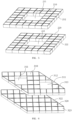
- Fig. 3 schematically illustrates an arrangement of detector arrays and window of the first flat plate 10 and the second flat plate 20 as shown in Fig. 2 .
- the first flat plate 10 and the second flat plate 20 each comprise a plurality of PET detectors 12, 22 arranged sequentially.
- the PET detectors 12, 22 may be connected to each other by conventional means, such as by means of mechanical parts or fixture connection.
- the first flat plate 10 and the second flat plate 20 as needed may have various shapes, such as a circle or a ring.
- the first flat plate 10 and the second flat plate 20 may be adjusted to be of different or same sizes as needed.
- the first flat plate 10 and the second flat plate 20 are each as a rectangular plate with the same size.
- the first flat plate 10 is formed with the window 11 by removing 3 by 3 PET detectors in the center.
- the size of the window 11 is approximately equal to nine times the area of one single PET detector 12.
- the area of the window 11 is integral multiple(s) of the area of one single PET detector.
- the individual PET detectors as needed may have different sizes by cutting, such that the area of one single window may be from 1 square centimeter to 1 square meter.
- the location, number and size of the window 11 is adjustable as needed.
- the location of the window may be variously adjusted in any flat plate, the number of the window may be two or more, or the first and second flat plates each may have the respective window.
- FIGS. 4 to 6 are for illustrative purpose only , but not as limitation.
- the first flat plate 110 formed in the first flat plate 110 are two windows 111, which are approximately arranged in the diagonal line of the first flat plate 110, each window 111 having an area four times that of the single PET detector.
- a window 211 which has an area nine times that of one single PET detector.
- a window 221 which has a location corresponding to that of window 211.
- the window 221 has an area nine times that of the single PET detector.
- the first flat plate 310 and the second flat plate 320 as illustrated each are irregular combined plate, that is, the first flat plate 310 and the second flat plate 320 each are formed by triangular PET detectors 312, 322 and square PET detector 313, 323 arranged sequentially.
- formed in the first flat plate 310 are two windows 311, each of which has an area about four times the area of the single PET detector 313.
- the disclosure it is proposed to use two parallel PET flat plates, which may be used for scanning and imaging in the procedure of treating tumors, so as to thus track and position the tumors cells in real time.
- a distance between the first flat plate 10 and the second flat plate 20 may be adjustable by means of a driving mechanism (not shown) along the first guiding rails 30, as illustrated in Fig. 2 , in order to better adapt to the size of the tumor region.
- the first flat plate 10 and the second flat plate 20 may be respectively moveable along the second guiding rails 40 in a direction perpendicular to the first guiding rails 30, such that a relative position between the first flat plate 10 and the second flat plate 20 may be adjustable so as to achieve an improved imaging effect.
- the first flat plate 10 and the second flat plate 20 may also be synchronically rotatable around the respective second guiding rail 40 so as to change an inclination direction and a relative position of the window(s). There will be little impact on the overall detection precision by arranging windows in the flat plate PET.
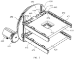
- Fig. 7 illustrated in Fig. 7 is another embodiment of the invention, in which numeral reference for the like element is indicated by numbers increased by 400, in which the first flat plate 410, the second flat plate 420, the first guiding rails 430, the second guiding rails 440 and the rotational stand 450 are all the same as those of the embodiment as shown in Fig. 1 .
- the embodiment further comprises a driving motor 460, which comprises a driving shaft on which a driving gear 461 is arranged, and third guiding rails 470.
- the fixing blocks 442 are each provided with a third fixing plate 472 which extends perpendicularly to the first guiding rails 430.
- a third guiding rail 470 perpendicular to the first guiding rails 430 and the third fixing plate 472.
- first flat plate 410 or the second flat plate 420 Arranged respectively on two opposite sides of the first flat plate 410 or the second flat plate 420 are two third sliding blocks 471, which are snapped into the third guiding rails 470, such that the first flat plate 410 or the second flat plate 420 may be slidable along the third guiding rails 470.
- the first flat plate 410 or the second flat plate 420 may realize three dimensional linear movements, i.e., along the first guiding rails 430, the second guiding rails 440 or the third guiding rails 470. They may also realize a rotational movement around the rotational stand 450.
- the first flat plate 410 and the second flat plate 420 may be positioned as desired according to the therapeutic requirement.
- the flat plate PET detection system with a window is able to facilitate positioning and navigation before the surgical operation or radiotherapy, effective identification of tissues such as residual lesions, necrotic lesions, and sub-clinical lesions, thereby improving the treatment success rate.
- it may be combined with other imaging device to perform same-bed, same-time, and multi-modal imaging, thereby eliminating the impact caused by the tissue variation within the scanning time difference and eliminating errors in the image merge. It may be used together with devices such as microscope and "Da Vince surgery system" for detecting and finding other physiological and biochemical phenomena in clinical or biological research.
- the window 11 may be configured to extend in a direction perpendicular to the first guiding rails 30 so as to divide the first flat plate 10 into two separate flat plates.
- the window 11 may be configured to extend in a direction perpendicular to the first guiding rails 30 so as to divide the first flat plate 10 into two separate flat plates.
- the window 211, 221 may be configured respectively to extend in a direction perpendicular to the first guiding rails so as to divide each of the first flat plate 210 and the second flat plate 220 into two separate flat plates.
- the support device in the disclosure may be configured as other form that is able to be universally moveable, which will not be elaborated here. There are conventional configurations that are not detailedly described herein and to be covered by the invention.
Landscapes
- Health & Medical Sciences (AREA)
- Life Sciences & Earth Sciences (AREA)
- Engineering & Computer Science (AREA)
- Medical Informatics (AREA)
- Biomedical Technology (AREA)
- Animal Behavior & Ethology (AREA)
- Veterinary Medicine (AREA)
- Nuclear Medicine, Radiotherapy & Molecular Imaging (AREA)
- Public Health (AREA)
- Pathology (AREA)
- Radiology & Medical Imaging (AREA)
- General Health & Medical Sciences (AREA)
- Molecular Biology (AREA)
- Physics & Mathematics (AREA)
- High Energy & Nuclear Physics (AREA)
- Heart & Thoracic Surgery (AREA)
- Surgery (AREA)
- Biophysics (AREA)
- Optics & Photonics (AREA)
- General Physics & Mathematics (AREA)
- Spectroscopy & Molecular Physics (AREA)
- Nuclear Medicine (AREA)
- Radiation-Therapy Devices (AREA)
Description
- The present disclosure relates to a medical device, specifically to a flat-plate PET imaging device with a window.
- Of all diseases cancers pose one of the most serious threats to human life. Currently, cancers are generally treated with surgical operation, radiotherapy and chemotherapy. Radiotherapy, which uses rays generated by radioactive isotopes, regular X rays generated by an X-ray generator, high-energy X-rays generated by accelerators, electronic beams, protons, fast neutrons and heavy particles generated by various accelerators to cure cancers, is an important method for treating cancers, and improvement of its efficacy is a research area attracting much study. Generally, the efficacy of radiotherapy can be improved by optimizing dosage distribution of the rays; while a key factor to the optimization of the dosage distribution of rays lies in obtaining precise physiological information on a tumor and surrounding tissues.
- It is often proposed, prior to surgery or radiotherapy, to perform positioning and navigation to obtain the physiological information of the tumor and the surrounding tissues, so as to improve the efficacy of radiotherapy. In the state of art, the positioning and navigation involves initial positioning of cancer cell regions of a diseased organ by means of a medical imaging device. Afterwards, the diseased organ is removed by surgical operation or radiotherapy. However, there exists the following problems with the present clinical radiotherapy navigation system.
- Firstly, currently the positioning and navigation are mostly based on anatomic images obtained by CT or the like, which cannot precisely identify hypoxic tissues and necrotic lesion. The efficacy of radioactive rays on the tumor is mainly manifested by the killing of active cancer cells, especially the oxygen-enriched cells. Rays act on the cells and cause ionization of water molecule, forming free radicals R·, such as OH· free radicals. If there are oxygen molecules in the cells, then the free radicals R· will conduct the following reaction: R·+O 2 →RO 2·, which will further produce products that is destructive to the molecules in the cells. The prerequisite of the above reaction is the presence of oxygen. Where the tumor tissue is in the hypoxic state, the efficacy of the rays on the tumor will be significantly degraded. Moreover, no radiation is needed to be emitted on the necrotic tissues. Therefore, radiation dosage for the hypoxic tissues and necrotic needs to be adjusted to minimize damage to the healthy tissues of a patient. Therefore, precise identification of the hypoxic tissues and necrotic lesion is of much importance.
- Secondly, the treatment of subclinical focus is to a certain extent aimless. Devices such as CT cannot efficiently position the subclinical focus, not to mention providing navigation for radiotherapy. A subclinical focus such as breast cancer is secondary symptoms that appears during the process of cancer incidence, and is typically adjacent to or at places spaced from the tumor. Sometimes there are multiple lesions, which appear to be negative and usually difficult to be identified under the microscope, let alone using regular clinical examination. Patients will very likely face failed treatment if their subclinical focuses were not eliminated.
- Thirdly, the positioning and navigation in the state of art cannot report to a doctor or medical physician the information of the tumor and surrounding tissues in real-time. During the radiotherapy, the free radicals will damage the living cells. For example, reduction in activity of tumorous tissues will cause reduction in partial pressure of oxygen, which will in turn lower the ray sensitivity of the lesions. As another example, due to the complexity of the physiological mechanism of human body, various accidental and unpredictable conditions may occur clinically, making it impossible to identify whether the rays will cause irrecoverable damages to the healthy tissues. Therefore, if it is possible to report the physiological feedback of the tumor and surrounding tissues in real-time, the dosage distribution could be adjusted before the rays might otherwise have caused irrecoverable damages to the healthy tissues, which will reduce the harm to the patients, improving the living quality and survival rate of the patients.
- Lastly, the dosage distribution obtained with the state of art is not precise enough. When planning the radiotherapy, the influence on the target volume of the repetition errors caused by the breath and organ movements as well as patient position should be taken into consideration, and therefore, to ensure the efficacy of the radiotherapy, the planned target region in the radiotherapy is generally larger than the actual target region by several centimeters. As a result, damages to the healthy tissues will be increased during the radiotherapy, especially when the target region overlaps with the ray-sensitive tissues. Then, there will be a dilemma in that if the target region or dosage is reduced to protect the healthy tissues which are sensitive to the rays, the lesions may not be affected effectively, while if a larger target region and a greater dosage are used to realize a better treatment, the tissues will experience extra radiation dosage, which will cause more serious damage to the tissues. Therefore, if the precision of the dosage distribution may be increased, the damages to the healthy tissues may be reduced.
- In summary, from the perspective of radiobiology, improvement on the efficacy of the radiotherapy requires for accurate illustration of the state and change of tissues in terms of physiological information by the radiotherapy navigation and observation device, prompt provision of related information to realize real-time navigation and feedback, and precise dosage distribution on the target region with high resolution.
- As a functional imaging technology, positron emission tomography (PET), in comparison with CT, has outstanding advantage in obtaining physiological information of the tumor and surrounding tissues during radiotherapy positioning and navigation. In the meantime, in comparison with MRI, it will not affect the surgical operation due to magnetization of the surgical device. Therefore, it is scientific and efficient to choose the PET imaging technology for radiotherapy navigation during tumor surgery.
- Traditional PET employs a plurality of detector components to form an enclosed imaging system of an approximal circular structure. For example, Taiga Yamaya of Japan proposed an Open PET (see An Initial Investigation of Open PET Geometries, 2007 IEEE Nuclear Science Symposium Conference Record), which has a circular detecting ring structure as illustrated in
Fig. 1 , featuring in using twodetection rings human body 3 through the space between the two detection rings. The method solves the problem that the detection rings block the radiotherapeutic rays. Since the sensitivity is proportional to the coverage angle of the detection rings, however, the coverage angle of Open PET decreases with the increase of the distance in the case of using the same number of detectors. In comparison with the traditional PET, the Open PET's sensitivity will be further degraded, which will deteriorate the imaging performance, making it impossible to perform real-time dynamic imaging during the radiotherapy navigation. In order to allow the field of view to cover most of a human torso, moreover, the clinical PET of circular structure typically has an internal diameter greater than 70cm, sometimes even up to 2 meters, which make the instrument bulky and of complicated structure, such that the medical physician has little operation space, and thus it is still difficult for the PET to be integrated with radiotherapy devices. -
WO 2010/136851 A1 describes an imaging device for positron emission tomography, comprising: a lateral detection module comprising a first group of detectors, disposed along a longitudinal direction on a lateral side of an examination volume, and having a longitudinal dimension along said longitudinal direction, and an adjusting device adapted to expand the lateral detection module in said longitudinal direction between a packed configuration and an expanded configuration. -
CN 104 856 716 A describes a partially dedicated flat PET imaging device comprising at least two sets of flat PET detectors and a robotic arm system that can support the detector to move in three directions and support the detector to rotate at an angle. -
US 2011/024637 A1 describes an open-type PET scanner in which detector rings arranged in a multilayered manner in an axial direction are at least partially opened and the thus opened part of the detector rings is at least partially included in a main focus region, wherein some of the detecting elements constituting the detector ring are disposed obliquely in the axial direction so that the main sensitivity direction thereof is turned closer to the main focus region, thereby increasing the resolution in the main focus region. - The invention is described in the independent claims.
- In the disclosure, an objective is to provide a flat-plate PET imaging device with a window, thereby solving the problems of unable to realize real-time positioning and scanning and not having enough operation space during radiotherapy navigation.
- In the disclosure, provided is a flat-plate PET imaging device with a window, which comprises: a first flat plate comprising a plurality of PET detectors that are arranged sequentially in a plate shape, and at least one window; a second flat plate comprising a plurality of PET detectors that are arranged in sequentially in a plate shape, the second flat plate being parallel to the first flat plate; and a support device to which the first flat plate and the second flat plate are fixed.
- The window has an area that is of integral multiple of an area of the PET detector.
- The area of the window is in a range of 1 square centimeter to 1 square meter.
- In an embodiment of the invention, the second flat plate comprises at least one window.
- In an embodiment of the invention, the first flat plate has a shape identical with that of the second flat plate.
- In an embodiment of the invention, the first flat plate has a shape different from that of the second flat plate.
- In an embodiment of the invention, the support device comprises: a rotational stand; two first guiding rails arranged in parallel to each other on the rotational stand, and at least two second guiding rails arranged perpendicularly to the first guiding rails and fixed to the first guiding rails by means of first sliding blocks, wherein the first flat plate and the second flat plate are hinged to the second guiding rails by means of second sliding blocks.
- The first sliding blocks each comprise a fixing plate arranged perpendicularly to the said first guiding rail and extending towards the other first guiding rail, wherein the second guiding rails are fixed to the fixing plates.
- In an embodiment of the disclosure, the support device further comprises a driving motor and a third guiding rail, wherein the rotational stand has a shape of circular, the driving motor comprises a driving gear that engages with the rotational stand, the third guiding rail is arranged perpendicularly to the first guiding rails and the second guiding rails respectively, and the first flat plate and the second flat plate are fixed to the third guiding rail by means of third sliding blocks.
- In an embodiment of the disclosure, the PET detector has a shape of triangle or parallelogram.
- In the disclosure, provided is a flat-plate PET imaging device with a window, which facilitates real-time diagnosis and positioning of cancerous cells during surgical operation or radiotherapy. It thus can illustrate distribution and physiological information of the cancerous cells in real-time, avoiding positioning errors caused by spreading or change of the cancerous cells. In the meantime, a window is arranged on the flat-plate PET, which helps to provide space for other operations such as radiotherapy while ensuring real-time positioning and scanning effects, thereby achieving real-time diagnosis as well as positioning and navigation without affecting the therapeutic procedure. Moreover, in the disclosure it has proposed to precisely reflect the state and change of tissues by using the physiological and biochemical information, realizing quick imaging during the radiotherapy navigation, thus providing basis and standard for improving the precision of the ray dosage distribution, thereby improving the therapeutic effect.
-
-
Fig. 1 schematically illustrates a circular detection ring structure of a conventional Open PET; -
Fig. 2 schematically illustrates a perspective view of a flat-plate PET imaging device with a window in accordance with an embodiment of the invention; -
Fig. 3 schematically illustrates an arrangement of detector arrays and window of the flat-plate PET imaging device with the window as shownFig. 2 ; -
Fig. 4 schematically illustrates an arrangement of detector arrays and window according to another embodiment of the invention; -
Fig. 5 schematically illustrates an arrangement of detector arrays and windows according to another embodiment of the invention; -
Fig. 6 schematically illustrates an arrangement of detector arrays and windows according to another embodiment of the invention; and -
Fig. 7 schematically illustrates a perspective view of a flat-plate PET imaging device with a window according to another embodiment of the invention. - In the following, the invention will be described further with reference to embodiments. It should be understood that the following embodiments are for illustrative instead of limitative purpose only.
-
Fig. 2 schematically illustrates a perspective view of a flat-plate PET imaging device with a window in accordance with an embodiment of the invention. In the disclosure, A the flat-plate PET imaging device as shown inFig. 2 comprises a firstflat plate 10, a secondflat plate 20 and a support device. The firstflat plate 10 and the secondflat plate 20 are arranged in parallel and fixed through the support device. Specifically, the support device comprises first guidingrails 30, second guiding rails 40 and arotational stand 50. The two first guiding rails 30 are arranged in parallel to each other, and disposed on a side of the circular flat-shapedrotational stand 50, each first guidingrail 30 being provided with two first slidingblocks 31, which are snapped onto and slidable along the first guiding rails 30. Each of the first slidingblock 31 is further provided with a fixingplate 41 perpendicular to the first guidingrail 30 and extending towards the opposite first guidingrail 30. The second guiding rails 40 are perpendicular to the first guiding rails 30 and fixed to the fixingplate 41 by way of fixing blocks 42. The firstflat plate 10 and the secondflat plate 20 are respectively hinged to the second guiding rails 40 through second slidingblocks 43, such that the firstflat plate 10 and the secondflat plate 20 can slide along the second guiding rails 40 while they are respectively rotatable around the second guiding rails 40. Formed in the firstflat plate 10 is awindow 11, which can facilitate the medical physician to perform other operations, such as introducing X-rays through thewindow 11, during the radiotherapy navigation. -
Fig. 3 schematically illustrates an arrangement of detector arrays and window of the firstflat plate 10 and the secondflat plate 20 as shown inFig. 2 . As shown inFig. 3 , the firstflat plate 10 and the secondflat plate 20 each comprise a plurality ofPET detectors PET detectors flat plate 10 and the secondflat plate 20 as needed may have various shapes, such as a circle or a ring. Similarly, the firstflat plate 10 and the secondflat plate 20 may be adjusted to be of different or same sizes as needed. InFig. 3 , the firstflat plate 10 and the secondflat plate 20 are each as a rectangular plate with the same size. Herein the firstflat plate 10 is formed with thewindow 11 by removing 3 by 3 PET detectors in the center. The size of thewindow 11 is approximately equal to nine times the area of onesingle PET detector 12. Generally, the area of thewindow 11 is integral multiple(s) of the area of one single PET detector. As the individual PET detectors as needed may have different sizes by cutting, such that the area of one single window may be from 1 square centimeter to 1 square meter. - It is noted that in the disclosure the location, number and size of the
window 11 is adjustable as needed. For example, the location of the window may be variously adjusted in any flat plate, the number of the window may be two or more, or the first and second flat plates each may have the respective window. Other embodiments are illustrated inFIGS. 4 to 6 , which are for illustrative purpose only , but not as limitation. - As illustrated in
Fig. 4 , in another embodiment of the invention, in which numeral reference for the like element is indicated by numbers increased by 100, formed in the firstflat plate 110 are twowindows 111, which are approximately arranged in the diagonal line of the firstflat plate 110, eachwindow 111 having an area four times that of the single PET detector. - As illustrated in
Fig. 5 , in another embodiment of the invention, in which numeral reference for the like element is indicated by numbers increased by 200, arranged on the firstflat plate 210 is awindow 211, which has an area nine times that of one single PET detector. Formed centrally in the secondflat plate 220 is awindow 221, which has a location corresponding to that ofwindow 211. Similarly, thewindow 221 has an area nine times that of the single PET detector. - Moreover, as illustrated in
Fig. 6 , in another embodiment of the invention, in which numeral reference for the like element is indicated by numbers increased by 300, the firstflat plate 310 and the secondflat plate 320 as illustrated each are irregular combined plate, that is, the firstflat plate 310 and the secondflat plate 320 each are formed bytriangular PET detectors square PET detector flat plate 310 are twowindows 311, each of which has an area about four times the area of thesingle PET detector 313. - In the disclosure, it is proposed to use two parallel PET flat plates, which may be used for scanning and imaging in the procedure of treating tumors, so as to thus track and position the tumors cells in real time. In the disclosure, it proposed to form window(s) in the PET plate(s) as needed, such that a spatial channel may be formed in the direction perpendicular to the flat plate(s) in between the two flat plate(s), thereby allowing enough space for the tumor treatment operation for the medical physician or for the rays to pass. Meanwhile, less detectors are required and thus the cost is reduced.
- In the disclosure, in use, a distance between the first
flat plate 10 and the secondflat plate 20 may be adjustable by means of a driving mechanism (not shown) along the first guiding rails 30, as illustrated inFig. 2 , in order to better adapt to the size of the tumor region. Meanwhile, the firstflat plate 10 and the secondflat plate 20 may be respectively moveable along the second guiding rails 40 in a direction perpendicular to the first guiding rails 30, such that a relative position between the firstflat plate 10 and the secondflat plate 20 may be adjustable so as to achieve an improved imaging effect. Moreover, the firstflat plate 10 and the secondflat plate 20 may also be synchronically rotatable around the respective second guidingrail 40 so as to change an inclination direction and a relative position of the window(s). There will be little impact on the overall detection precision by arranging windows in the flat plate PET. - Moreover, illustrated in
Fig. 7 is another embodiment of the invention, in which numeral reference for the like element is indicated by numbers increased by 400, in which the firstflat plate 410, the secondflat plate 420, the first guiding rails 430, the second guiding rails 440 and therotational stand 450 are all the same as those of the embodiment as shown inFig. 1 . In the following only the different elements will be described. InFig. 7 , the embodiment further comprises a drivingmotor 460, which comprises a driving shaft on which adriving gear 461 is arranged, and third guiding rails 470. Arranged circumferentially on therotational stand 450 are engagingteeth 451 which are configured to engage with thedriving gear 461 such that therotational stand 450 is driven to rotate by the drivingmotor 460, such that the firstflat plate 410 and the secondflat plate 420 are rotated to the required positions. The fixing blocks 442 are each provided with athird fixing plate 472 which extends perpendicularly to the first guiding rails 430. Arranged on thethird fixing plate 472 is athird guiding rail 470 perpendicular to the first guiding rails 430 and thethird fixing plate 472. Arranged respectively on two opposite sides of the firstflat plate 410 or the secondflat plate 420 are two third slidingblocks 471, which are snapped into the third guiding rails 470, such that the firstflat plate 410 or the secondflat plate 420 may be slidable along the third guiding rails 470. In the embodiment, the firstflat plate 410 or the secondflat plate 420 may realize three dimensional linear movements, i.e., along the first guiding rails 430, the second guiding rails 440 or the third guiding rails 470. They may also realize a rotational movement around therotational stand 450. As a result, the firstflat plate 410 and the secondflat plate 420 may be positioned as desired according to the therapeutic requirement. - In the disclosure, the flat plate PET detection system with a window is able to facilitate positioning and navigation before the surgical operation or radiotherapy, effective identification of tissues such as residual lesions, necrotic lesions, and sub-clinical lesions, thereby improving the treatment success rate. In the disclosure, it may be combined with other imaging device to perform same-bed, same-time, and multi-modal imaging, thereby eliminating the impact caused by the tissue variation within the scanning time difference and eliminating errors in the image merge. It may be used together with devices such as microscope and "Da Vince surgery system" for detecting and finding other physiological and biochemical phenomena in clinical or biological research.
- What is described above is preferred embodiments of the invention and shall not be construed as limitation to the scope of the invention. It should be understood that various alternatives to the embodiments of the invention described herein may be employed. It is thus intended that apparent or equivalent changes and variations to the embodiments as recited in the claims and description, which are considered to be within the ability of those skilled in the art, are all to be within the scope of the invention. For example, in
Fig. 2 thewindow 11 may be configured to extend in a direction perpendicular to the first guiding rails 30 so as to divide the firstflat plate 10 into two separate flat plates. As another example, inFig. 5 thewindow flat plate 210 and the secondflat plate 220 into two separate flat plates. As still another example, the support device in the disclosure may be configured as other form that is able to be universally moveable, which will not be elaborated here. There are conventional configurations that are not detailedly described herein and to be covered by the invention.
Claims (9)
- A flat-plate positron emission tomography (PET) imaging device with a window (11, 111, 211, 311), wherein the flat-plate PET imaging device comprises:a first flat plate (10, 110, 210, 310, 410) comprising a plurality of PET detectors (12, 112, 212, 312, 313) that are arranged sequentially in a plate shape, and at least one first window (11, 111, 211, 311) for providing space for other operations;a second flat plate (20, 120, 220, 320, 420) comprising a plurality of PET detectors (22, 122, 222, 322, 323) that are arranged sequentially in a plate shape, the second flat plate (20, 120, 220, 320, 420) being parallel to the first flat plate (10, 110, 210, 310, 410); anda support device to which the first flat plate (10, 110, 210, 310, 410) and the second flat plate (20, 120, 220, 320, 420) are fixed, wherein the support device comprises:a rotational stand (50, 450);two first guiding rails (30, 430) arranged in parallel to each other on the rotational stand (50, 450); andat least two second guiding rails (40, 440) arranged perpendicularly to the first guiding rails (30, 430) and fixed to the first guiding rails (30, 430) by means of first sliding blocks (31), wherein the first flat plate (10, 110, 210, 310, 410) and the second flat plate are hinged to the second guiding rails (40, 440) by means of second sliding blocks (43).
- The flat-plate PET imaging device with the window (11, 111, 211, 311) of claim 1, wherein the area of the window (11, 111, 211, 311) is in a range of 1 square centimeter to 1 square meter.
- The flat-plate PET imaging device with the window (11, 111, 211, 311) of any of claims 1 to 2, wherein the second flat plate (20, 120, 220, 320, 420) comprises at least one second window (11, 111, 211, 311).
- The flat-plate PET imaging device with the window (11, 111, 211, 311) of any of claims 1 to 3, wherein the first flat plate (10, 110, 210, 310, 410) has a shape identical with that the second flat plate (20, 120, 220, 320, 420).
- The flat-plate PET imaging device with the window (11, 111, 211, 311) of any of claims 1 to 3, wherein the first flat plate (10, 110, 210, 310, 410) has a shape different from that of the second flat plate (20, 120, 220, 320, 420).
- The flat-plate PET imaging device with the window (11, 111, 211, 311) of any of claims 1 to 5, wherein the first window (11, 111, 211, 311) has an area that is of integral multiple of an area of one of the PET detectors (12, 112, 212, 312, 313) in the first flat plate (10, 110, 210, 310, 410).
- The flat-plate PET imaging device with the window (11, 111, 211, 311) of any of claims 1 to 6, wherein the first sliding blocks (31) each comprise a fixing plate (41) arranged perpendicularly to the first guiding rail (30, 430) and extending towards the other first guiding rail (30, 430), wherein the second guiding rails (40, 440) are fixed to the fixing plates (41).
- The flat-plate PET imaging device with the window (11, 111, 211, 311) of any of claims 1 to 7, wherein the support device further comprises a driving motor (460) and a third guiding rail (470), wherein the rotational stand (50,450) has a shape of circular, the driving motor (460) comprises a driving gear that engages with the rotational stand (50, 450), the third guiding rail (470) is arranged perpendicularly to the first guiding rails (30, 430) and the second guiding rails (40, 440) respectively, and the first flat plate (10, 110, 210, 310, 410) and the second flat plate (20, 120, 220, 320, 420) are fixed to the third guiding rail (470) by means of third sliding blocks (471).
- The flat-plate PET imaging device with the window (11, 111, 211, 311) of any of claims 1 to 8, wherein the PET detector has a shape of triangle or parallelogram.
Applications Claiming Priority (2)
| Application Number | Priority Date | Filing Date | Title |
|---|---|---|---|
| CN201511019068.5A CN106923860B (en) | 2015-12-30 | 2015-12-30 | Flat PET imaging device with window |
| PCT/CN2016/107263 WO2017114046A1 (en) | 2015-12-30 | 2016-11-25 | Flat-panel pet imaging device with window |
Publications (3)
| Publication Number | Publication Date |
|---|---|
| EP3398518A1 EP3398518A1 (en) | 2018-11-07 |
| EP3398518A4 EP3398518A4 (en) | 2019-07-31 |
| EP3398518B1 true EP3398518B1 (en) | 2024-12-04 |
Family
ID=59225583
Family Applications (1)
| Application Number | Title | Priority Date | Filing Date |
|---|---|---|---|
| EP16880836.8A Active EP3398518B1 (en) | 2015-12-30 | 2016-11-25 | Flat-panel pet imaging device with window |
Country Status (6)
| Country | Link |
|---|---|
| US (1) | US10459095B2 (en) |
| EP (1) | EP3398518B1 (en) |
| JP (1) | JP6667643B2 (en) |
| CN (1) | CN106923860B (en) |
| FI (1) | FI3398518T3 (en) |
| WO (1) | WO2017114046A1 (en) |
Families Citing this family (1)
| Publication number | Priority date | Publication date | Assignee | Title |
|---|---|---|---|---|
| CN112169194A (en) * | 2020-10-30 | 2021-01-05 | 山东新华医疗器械股份有限公司 | Image and dosage integrated device |
Family Cites Families (12)
| Publication number | Priority date | Publication date | Assignee | Title |
|---|---|---|---|---|
| WO2009122561A1 (en) * | 2008-04-01 | 2009-10-08 | 独立行政法人放射線医学総合研究所 | Open type pet device |
| KR100878881B1 (en) * | 2008-06-17 | 2009-01-15 | (주) 뉴캐어메디컬시스템 | Integrated PET / CT System |
| JP2010032451A (en) * | 2008-07-31 | 2010-02-12 | Hitachi Ltd | Particle beam irradiation system |
| JP4703703B2 (en) * | 2008-09-30 | 2011-06-15 | 株式会社東芝 | Nuclear medicine diagnostic equipment |
| US7858944B2 (en) * | 2009-01-23 | 2010-12-28 | Jefferson Science Associates, Llc | Dedicated mobile high resolution prostate PET imager with an insertable transrectal probe |
| WO2010136851A1 (en) * | 2009-05-26 | 2010-12-02 | Biospace Lab | Imaging device for positron emission tomography |
| FR2970339B1 (en) * | 2011-01-10 | 2013-02-08 | Commissariat Energie Atomique | NUCLEAR MATERIAL DETECTION PROCESS BY NEUTRONIC INTERROGATION AND ASSOCIATED DETECTION SYSTEM |
| JP2016530912A (en) | 2013-07-10 | 2016-10-06 | アリネータ・リミテッド | Radiation window for medical imaging system |
| WO2015044019A1 (en) * | 2013-09-27 | 2015-04-02 | Koninklijke Philips N.V. | Multimodal imaging apparatus |
| CN104856716A (en) * | 2014-02-24 | 2015-08-26 | 苏州瑞派宁科技有限公司 | Panel PET imaging device and method special for local and radiotherapy |
| CN105105781B (en) | 2015-09-17 | 2018-03-06 | 武汉瑞福宁科技有限公司 | A kind of flat board PET system and purposes |
| CN205433730U (en) * | 2015-12-30 | 2016-08-10 | 苏州瑞派宁科技有限公司 | Dull and stereotyped PET image device with window |
-
2015
- 2015-12-30 CN CN201511019068.5A patent/CN106923860B/en active Active
-
2016
- 2016-11-25 WO PCT/CN2016/107263 patent/WO2017114046A1/en not_active Ceased
- 2016-11-25 FI FIEP16880836.8T patent/FI3398518T3/en active
- 2016-11-25 EP EP16880836.8A patent/EP3398518B1/en active Active
- 2016-11-25 JP JP2018534081A patent/JP6667643B2/en active Active
- 2016-11-25 US US16/067,579 patent/US10459095B2/en active Active
Also Published As
| Publication number | Publication date |
|---|---|
| FI3398518T3 (en) | 2025-01-23 |
| US20190011580A1 (en) | 2019-01-10 |
| WO2017114046A1 (en) | 2017-07-06 |
| CN106923860B (en) | 2023-08-22 |
| JP2019504314A (en) | 2019-02-14 |
| EP3398518A4 (en) | 2019-07-31 |
| JP6667643B2 (en) | 2020-03-18 |
| CN106923860A (en) | 2017-07-07 |
| US10459095B2 (en) | 2019-10-29 |
| EP3398518A1 (en) | 2018-11-07 |
Similar Documents
| Publication | Publication Date | Title |
|---|---|---|
| JP4756425B2 (en) | PET apparatus and image reconstruction method thereof | |
| US20150208994A1 (en) | Ct/mri integrated system for the diagnosis of acute strokes and methods thereof | |
| CN101961530B (en) | Image-guided radiation therapy equipment | |
| US8461539B2 (en) | Combined radiation therapy/pet apparatus | |
| EP2535086B1 (en) | Integration of MRI into radiation therapy treatment | |
| US6888919B2 (en) | Radiotherapy apparatus equipped with an articulable gantry for positioning an imaging unit | |
| US20070153969A1 (en) | Radiotherapeutic device | |
| EP3056245A1 (en) | Radiation therapy guided using pet imaging | |
| US20130237822A1 (en) | Combined radiotherapy ultrasound device | |
| US11400314B2 (en) | Photon emission detection device and neutron capture therapy system with the same | |
| CN104856716A (en) | Panel PET imaging device and method special for local and radiotherapy | |
| WO2014183642A1 (en) | Radiotherapy device | |
| CN108295386A (en) | Radiotherapy equipment | |
| US10459095B2 (en) | Flat-plate PET imaging device with window | |
| WO2020038224A1 (en) | Source carrier, radiotherapy equipment, and control driving method therefor | |
| US9538964B2 (en) | Inclined pet device and pet combined device | |
| CN205433730U (en) | Dull and stereotyped PET image device with window | |
| CN112933423A (en) | Medical hybrid device | |
| WO2017083611A1 (en) | System and method for improved performance in nuclear medicine imaging | |
| KR101540961B1 (en) | Using magnetic resonance imaging portable radiation therapy system | |
| CN224085839U (en) | A radiotherapy system | |
| WO2025008712A1 (en) | Integrated system for non-invasive stereotactic radiosurgery with spect/pet 3d targeting for enhanced cancer treatment | |
| Lu et al. | Endoscopic 3-dimensional OCT-guided brachytherapy for early-stage pancreatic cancers | |
| KR20150059238A (en) | Radiation therapy system using MRI with improved RF coils | |
| Karaliova et al. | Individual planning and in vivo dosimetry of radiation therapy for cancer of the cervix and body of uterus |
Legal Events
| Date | Code | Title | Description |
|---|---|---|---|
| STAA | Information on the status of an ep patent application or granted ep patent |
Free format text: STATUS: THE INTERNATIONAL PUBLICATION HAS BEEN MADE |
|
| PUAI | Public reference made under article 153(3) epc to a published international application that has entered the european phase |
Free format text: ORIGINAL CODE: 0009012 |
|
| STAA | Information on the status of an ep patent application or granted ep patent |
Free format text: STATUS: REQUEST FOR EXAMINATION WAS MADE |
|
| 17P | Request for examination filed |
Effective date: 20180620 |
|
| AK | Designated contracting states |
Kind code of ref document: A1 Designated state(s): AL AT BE BG CH CY CZ DE DK EE ES FI FR GB GR HR HU IE IS IT LI LT LU LV MC MK MT NL NO PL PT RO RS SE SI SK SM TR |
|
| AX | Request for extension of the european patent |
Extension state: BA ME |
|
| DAV | Request for validation of the european patent (deleted) | ||
| DAX | Request for extension of the european patent (deleted) | ||
| A4 | Supplementary search report drawn up and despatched |
Effective date: 20190628 |
|
| RIC1 | Information provided on ipc code assigned before grant |
Ipc: A61B 6/12 20060101AFI20190624BHEP Ipc: A61B 6/00 20060101ALI20190624BHEP Ipc: A61N 5/10 20060101ALN20190624BHEP |
|
| STAA | Information on the status of an ep patent application or granted ep patent |
Free format text: STATUS: EXAMINATION IS IN PROGRESS |
|
| 17Q | First examination report despatched |
Effective date: 20211116 |
|
| REG | Reference to a national code |
Ref country code: DE Free format text: PREVIOUS MAIN CLASS: A61B0006120000 Ref country code: DE Ref legal event code: R079 Ref document number: 602016090542 Country of ref document: DE Free format text: PREVIOUS MAIN CLASS: A61B0006120000 Ipc: A61B0006030000 |
|
| GRAP | Despatch of communication of intention to grant a patent |
Free format text: ORIGINAL CODE: EPIDOSNIGR1 |
|
| STAA | Information on the status of an ep patent application or granted ep patent |
Free format text: STATUS: GRANT OF PATENT IS INTENDED |
|
| INTG | Intention to grant announced |
Effective date: 20240722 |
|
| RIC1 | Information provided on ipc code assigned before grant |
Ipc: A61N 5/10 20060101ALN20240712BHEP Ipc: A61B 6/42 20240101ALI20240712BHEP Ipc: A61B 6/12 20060101ALI20240712BHEP Ipc: A61B 6/03 20060101AFI20240712BHEP |
|
| RIN1 | Information on inventor provided before grant (corrected) |
Inventor name: XIE, QINGGUO Inventor name: GUO, YANBIN Inventor name: XIAO, PENG Inventor name: LI, BINGXUAN |
|
| GRAS | Grant fee paid |
Free format text: ORIGINAL CODE: EPIDOSNIGR3 |
|
| GRAA | (expected) grant |
Free format text: ORIGINAL CODE: 0009210 |
|
| STAA | Information on the status of an ep patent application or granted ep patent |
Free format text: STATUS: THE PATENT HAS BEEN GRANTED |
|
| AK | Designated contracting states |
Kind code of ref document: B1 Designated state(s): AL AT BE BG CH CY CZ DE DK EE ES FI FR GB GR HR HU IE IS IT LI LT LU LV MC MK MT NL NO PL PT RO RS SE SI SK SM TR |
|
| REG | Reference to a national code |
Ref country code: GB Ref legal event code: FG4D |
|
| REG | Reference to a national code |
Ref country code: CH Ref legal event code: EP |
|
| REG | Reference to a national code |
Ref country code: DE Ref legal event code: R096 Ref document number: 602016090542 Country of ref document: DE |
|
| REG | Reference to a national code |
Ref country code: IE Ref legal event code: FG4D |
|
| REG | Reference to a national code |
Ref country code: FI Ref legal event code: FGE |
|
| REG | Reference to a national code |
Ref country code: LT Ref legal event code: MG9D |
|
| REG | Reference to a national code |
Ref country code: NL Ref legal event code: MP Effective date: 20241204 |
|
| PG25 | Lapsed in a contracting state [announced via postgrant information from national office to epo] |
Ref country code: HR Free format text: LAPSE BECAUSE OF FAILURE TO SUBMIT A TRANSLATION OF THE DESCRIPTION OR TO PAY THE FEE WITHIN THE PRESCRIBED TIME-LIMIT Effective date: 20241204 |
|
| PG25 | Lapsed in a contracting state [announced via postgrant information from national office to epo] |
Ref country code: BG Free format text: LAPSE BECAUSE OF FAILURE TO SUBMIT A TRANSLATION OF THE DESCRIPTION OR TO PAY THE FEE WITHIN THE PRESCRIBED TIME-LIMIT Effective date: 20241204 |
|
| PG25 | Lapsed in a contracting state [announced via postgrant information from national office to epo] |
Ref country code: ES Free format text: LAPSE BECAUSE OF FAILURE TO SUBMIT A TRANSLATION OF THE DESCRIPTION OR TO PAY THE FEE WITHIN THE PRESCRIBED TIME-LIMIT Effective date: 20241204 |
|
| PG25 | Lapsed in a contracting state [announced via postgrant information from national office to epo] |
Ref country code: NO Free format text: LAPSE BECAUSE OF FAILURE TO SUBMIT A TRANSLATION OF THE DESCRIPTION OR TO PAY THE FEE WITHIN THE PRESCRIBED TIME-LIMIT Effective date: 20250304 |
|
| PG25 | Lapsed in a contracting state [announced via postgrant information from national office to epo] |
Ref country code: GR Free format text: LAPSE BECAUSE OF FAILURE TO SUBMIT A TRANSLATION OF THE DESCRIPTION OR TO PAY THE FEE WITHIN THE PRESCRIBED TIME-LIMIT Effective date: 20250305 Ref country code: LV Free format text: LAPSE BECAUSE OF FAILURE TO SUBMIT A TRANSLATION OF THE DESCRIPTION OR TO PAY THE FEE WITHIN THE PRESCRIBED TIME-LIMIT Effective date: 20241204 |
|
| PG25 | Lapsed in a contracting state [announced via postgrant information from national office to epo] |
Ref country code: RS Free format text: LAPSE BECAUSE OF FAILURE TO SUBMIT A TRANSLATION OF THE DESCRIPTION OR TO PAY THE FEE WITHIN THE PRESCRIBED TIME-LIMIT Effective date: 20250304 |
|
| PG25 | Lapsed in a contracting state [announced via postgrant information from national office to epo] |
Ref country code: NL Free format text: LAPSE BECAUSE OF FAILURE TO SUBMIT A TRANSLATION OF THE DESCRIPTION OR TO PAY THE FEE WITHIN THE PRESCRIBED TIME-LIMIT Effective date: 20241204 |
|
| REG | Reference to a national code |
Ref country code: AT Ref legal event code: MK05 Ref document number: 1747255 Country of ref document: AT Kind code of ref document: T Effective date: 20241204 |
|
| PG25 | Lapsed in a contracting state [announced via postgrant information from national office to epo] |
Ref country code: SM Free format text: LAPSE BECAUSE OF FAILURE TO SUBMIT A TRANSLATION OF THE DESCRIPTION OR TO PAY THE FEE WITHIN THE PRESCRIBED TIME-LIMIT Effective date: 20241204 |
|
| PG25 | Lapsed in a contracting state [announced via postgrant information from national office to epo] |
Ref country code: PL Free format text: LAPSE BECAUSE OF FAILURE TO SUBMIT A TRANSLATION OF THE DESCRIPTION OR TO PAY THE FEE WITHIN THE PRESCRIBED TIME-LIMIT Effective date: 20241204 |
|
| PG25 | Lapsed in a contracting state [announced via postgrant information from national office to epo] |
Ref country code: IS Free format text: LAPSE BECAUSE OF FAILURE TO SUBMIT A TRANSLATION OF THE DESCRIPTION OR TO PAY THE FEE WITHIN THE PRESCRIBED TIME-LIMIT Effective date: 20250404 |
|
| PG25 | Lapsed in a contracting state [announced via postgrant information from national office to epo] |
Ref country code: PT Free format text: LAPSE BECAUSE OF FAILURE TO SUBMIT A TRANSLATION OF THE DESCRIPTION OR TO PAY THE FEE WITHIN THE PRESCRIBED TIME-LIMIT Effective date: 20250404 |
|
| PG25 | Lapsed in a contracting state [announced via postgrant information from national office to epo] |
Ref country code: EE Free format text: LAPSE BECAUSE OF FAILURE TO SUBMIT A TRANSLATION OF THE DESCRIPTION OR TO PAY THE FEE WITHIN THE PRESCRIBED TIME-LIMIT Effective date: 20241204 |
|
| PG25 | Lapsed in a contracting state [announced via postgrant information from national office to epo] |
Ref country code: AT Free format text: LAPSE BECAUSE OF FAILURE TO SUBMIT A TRANSLATION OF THE DESCRIPTION OR TO PAY THE FEE WITHIN THE PRESCRIBED TIME-LIMIT Effective date: 20241204 Ref country code: RO Free format text: LAPSE BECAUSE OF FAILURE TO SUBMIT A TRANSLATION OF THE DESCRIPTION OR TO PAY THE FEE WITHIN THE PRESCRIBED TIME-LIMIT Effective date: 20241204 |
|
| PG25 | Lapsed in a contracting state [announced via postgrant information from national office to epo] |
Ref country code: SK Free format text: LAPSE BECAUSE OF FAILURE TO SUBMIT A TRANSLATION OF THE DESCRIPTION OR TO PAY THE FEE WITHIN THE PRESCRIBED TIME-LIMIT Effective date: 20241204 |
|
| PG25 | Lapsed in a contracting state [announced via postgrant information from national office to epo] |
Ref country code: CZ Free format text: LAPSE BECAUSE OF FAILURE TO SUBMIT A TRANSLATION OF THE DESCRIPTION OR TO PAY THE FEE WITHIN THE PRESCRIBED TIME-LIMIT Effective date: 20241204 |
|
| REG | Reference to a national code |
Ref country code: DE Ref legal event code: R097 Ref document number: 602016090542 Country of ref document: DE |
|
| PG25 | Lapsed in a contracting state [announced via postgrant information from national office to epo] |
Ref country code: SE Free format text: LAPSE BECAUSE OF FAILURE TO SUBMIT A TRANSLATION OF THE DESCRIPTION OR TO PAY THE FEE WITHIN THE PRESCRIBED TIME-LIMIT Effective date: 20241204 |
|
| PG25 | Lapsed in a contracting state [announced via postgrant information from national office to epo] |
Ref country code: DK Free format text: LAPSE BECAUSE OF FAILURE TO SUBMIT A TRANSLATION OF THE DESCRIPTION OR TO PAY THE FEE WITHIN THE PRESCRIBED TIME-LIMIT Effective date: 20241204 |
|
| PLBE | No opposition filed within time limit |
Free format text: ORIGINAL CODE: 0009261 |
|
| STAA | Information on the status of an ep patent application or granted ep patent |
Free format text: STATUS: NO OPPOSITION FILED WITHIN TIME LIMIT |
|
| REG | Reference to a national code |
Ref country code: CH Ref legal event code: L10 Free format text: ST27 STATUS EVENT CODE: U-0-0-L10-L00 (AS PROVIDED BY THE NATIONAL OFFICE) Effective date: 20251015 |
|
| 26N | No opposition filed |
Effective date: 20250905 |
|
| REG | Reference to a national code |
Ref country code: CH Ref legal event code: U11 Free format text: ST27 STATUS EVENT CODE: U-0-0-U10-U11 (AS PROVIDED BY THE NATIONAL OFFICE) Effective date: 20251201 |
|
| PGFP | Annual fee paid to national office [announced via postgrant information from national office to epo] |
Ref country code: DE Payment date: 20251117 Year of fee payment: 10 |
|
| PGFP | Annual fee paid to national office [announced via postgrant information from national office to epo] |
Ref country code: GB Payment date: 20251226 Year of fee payment: 10 |
|
| PGFP | Annual fee paid to national office [announced via postgrant information from national office to epo] |
Ref country code: FI Payment date: 20251024 Year of fee payment: 10 Ref country code: IT Payment date: 20251107 Year of fee payment: 10 |
|
| PGFP | Annual fee paid to national office [announced via postgrant information from national office to epo] |
Ref country code: FR Payment date: 20251127 Year of fee payment: 10 |
|
| PGFP | Annual fee paid to national office [announced via postgrant information from national office to epo] |
Ref country code: CH Payment date: 20251201 Year of fee payment: 10 |