EP3398428B1 - Power modulating motor control method - Google Patents
Power modulating motor control method Download PDFInfo
- Publication number
- EP3398428B1 EP3398428B1 EP18170281.2A EP18170281A EP3398428B1 EP 3398428 B1 EP3398428 B1 EP 3398428B1 EP 18170281 A EP18170281 A EP 18170281A EP 3398428 B1 EP3398428 B1 EP 3398428B1
- Authority
- EP
- European Patent Office
- Prior art keywords
- motor
- power mode
- control system
- load
- level
- Prior art date
- Legal status (The legal status is an assumption and is not a legal conclusion. Google has not performed a legal analysis and makes no representation as to the accuracy of the status listed.)
- Active
Links
Images


Classifications
-
- H—ELECTRICITY
- H02—GENERATION; CONVERSION OR DISTRIBUTION OF ELECTRIC POWER
- H02P—CONTROL OR REGULATION OF ELECTRIC MOTORS, ELECTRIC GENERATORS OR DYNAMO-ELECTRIC CONVERTERS; CONTROLLING TRANSFORMERS, REACTORS OR CHOKE COILS
- H02P29/00—Arrangements for regulating or controlling electric motors, appropriate for both AC and DC motors
- H02P29/40—Regulating or controlling the amount of current drawn or delivered by the motor for controlling the mechanical load
-
- A—HUMAN NECESSITIES
- A01—AGRICULTURE; FORESTRY; ANIMAL HUSBANDRY; HUNTING; TRAPPING; FISHING
- A01G—HORTICULTURE; CULTIVATION OF VEGETABLES, FLOWERS, RICE, FRUIT, VINES, HOPS OR SEAWEED; FORESTRY; WATERING
- A01G3/00—Cutting implements specially adapted for horticultural purposes; Delimbing standing trees
- A01G3/02—Secateurs; Flower or fruit shears
- A01G3/033—Secateurs; Flower or fruit shears having motor-driven blades
- A01G3/037—Secateurs; Flower or fruit shears having motor-driven blades the driving means being an electric motor
-
- A—HUMAN NECESSITIES
- A01—AGRICULTURE; FORESTRY; ANIMAL HUSBANDRY; HUNTING; TRAPPING; FISHING
- A01G—HORTICULTURE; CULTIVATION OF VEGETABLES, FLOWERS, RICE, FRUIT, VINES, HOPS OR SEAWEED; FORESTRY; WATERING
- A01G3/00—Cutting implements specially adapted for horticultural purposes; Delimbing standing trees
- A01G3/04—Apparatus for trimming hedges, e.g. hedge shears
- A01G3/047—Apparatus for trimming hedges, e.g. hedge shears portable
- A01G3/053—Apparatus for trimming hedges, e.g. hedge shears portable motor-driven
-
- A—HUMAN NECESSITIES
- A01—AGRICULTURE; FORESTRY; ANIMAL HUSBANDRY; HUNTING; TRAPPING; FISHING
- A01G—HORTICULTURE; CULTIVATION OF VEGETABLES, FLOWERS, RICE, FRUIT, VINES, HOPS OR SEAWEED; FORESTRY; WATERING
- A01G3/00—Cutting implements specially adapted for horticultural purposes; Delimbing standing trees
- A01G3/06—Hand-held edge trimmers or shears for lawns
- A01G3/062—Motor-driven edge trimmers
-
- B—PERFORMING OPERATIONS; TRANSPORTING
- B25—HAND TOOLS; PORTABLE POWER-DRIVEN TOOLS; MANIPULATORS
- B25F—COMBINATION OR MULTI-PURPOSE TOOLS NOT OTHERWISE PROVIDED FOR; DETAILS OR COMPONENTS OF PORTABLE POWER-DRIVEN TOOLS NOT PARTICULARLY RELATED TO THE OPERATIONS PERFORMED AND NOT OTHERWISE PROVIDED FOR
- B25F5/00—Details or components of portable power-driven tools not particularly related to the operations performed and not otherwise provided for
-
- H—ELECTRICITY
- H02—GENERATION; CONVERSION OR DISTRIBUTION OF ELECTRIC POWER
- H02H—EMERGENCY PROTECTIVE CIRCUIT ARRANGEMENTS
- H02H7/00—Emergency protective circuit arrangements specially adapted for specific types of electric machines or apparatus or for sectionalised protection of cable or line systems, and effecting automatic switching in the event of an undesired change from normal working conditions
- H02H7/08—Emergency protective circuit arrangements specially adapted for specific types of electric machines or apparatus or for sectionalised protection of cable or line systems, and effecting automatic switching in the event of an undesired change from normal working conditions for dynamo-electric motors
-
- H—ELECTRICITY
- H02—GENERATION; CONVERSION OR DISTRIBUTION OF ELECTRIC POWER
- H02P—CONTROL OR REGULATION OF ELECTRIC MOTORS, ELECTRIC GENERATORS OR DYNAMO-ELECTRIC CONVERTERS; CONTROLLING TRANSFORMERS, REACTORS OR CHOKE COILS
- H02P29/00—Arrangements for regulating or controlling electric motors, appropriate for both AC and DC motors
- H02P29/02—Providing protection against overload without automatic interruption of supply
-
- H—ELECTRICITY
- H02—GENERATION; CONVERSION OR DISTRIBUTION OF ELECTRIC POWER
- H02P—CONTROL OR REGULATION OF ELECTRIC MOTORS, ELECTRIC GENERATORS OR DYNAMO-ELECTRIC CONVERTERS; CONTROLLING TRANSFORMERS, REACTORS OR CHOKE COILS
- H02P29/00—Arrangements for regulating or controlling electric motors, appropriate for both AC and DC motors
- H02P29/02—Providing protection against overload without automatic interruption of supply
- H02P29/032—Preventing damage to the motor, e.g. setting individual current limits for different drive conditions
-
- A—HUMAN NECESSITIES
- A01—AGRICULTURE; FORESTRY; ANIMAL HUSBANDRY; HUNTING; TRAPPING; FISHING
- A01D—HARVESTING; MOWING
- A01D34/00—Mowers; Mowing apparatus of harvesters
- A01D34/01—Mowers; Mowing apparatus of harvesters characterised by features relating to the type of cutting apparatus
- A01D34/412—Mowers; Mowing apparatus of harvesters characterised by features relating to the type of cutting apparatus having rotating cutters
- A01D34/416—Flexible line cutters
-
- A—HUMAN NECESSITIES
- A01—AGRICULTURE; FORESTRY; ANIMAL HUSBANDRY; HUNTING; TRAPPING; FISHING
- A01D—HARVESTING; MOWING
- A01D34/00—Mowers; Mowing apparatus of harvesters
- A01D34/835—Mowers; Mowing apparatus of harvesters specially adapted for particular purposes
- A01D34/84—Mowers; Mowing apparatus of harvesters specially adapted for particular purposes for edges of lawns or fields, e.g. for mowing close to trees or walls
-
- B—PERFORMING OPERATIONS; TRANSPORTING
- B27—WORKING OR PRESERVING WOOD OR SIMILAR MATERIAL; NAILING OR STAPLING MACHINES IN GENERAL
- B27B—SAWS FOR WOOD OR SIMILAR MATERIAL; COMPONENTS OR ACCESSORIES THEREFOR
- B27B17/00—Chain saws; Equipment therefor
- B27B17/08—Drives or gearings; Devices for swivelling or tilting the chain saw
Definitions
- Embodiments herein relate to the field of electric tools, and, more specifically, to devices, methods, and systems for electric motors to automatically adjust their power output in response to load.
- Hand held electric power tools such as string trimmers, hedge trimmers, chain saws, and pole saws, include an electric motor.
- these tools are ideal for cutting large areas of thin branches and stems.
- the electric motor of the hedge trimmer may experience a stall as the larger branches become lodged in the cutting blades of the hedge trimmer.
- EP2685627 discloses a power tool including a voltage increasing circuit connected to a power supply to regulate power supplied to a load.
- US 2013/020102 discloses A battery-operated power tool comprising a working element, a motor arranged to drive the working element and a controller arranged to control the speed at which the motor drives the working element, in which there is provided a sensor for at least one factor, typically the pressure which the user is applying the power tool, indicative of the efficiency with which the power tool is being operated.
- the controller is arranged to vary the speed at which the motor drives the working element should the factor indicate that the power tool is being operated in a sub-optimal manner.
- WO2010098149 and JP5337274 each disclose a garden clipper comprising a pair of shear blades; a motor for reciprocating one and/or the other of the pair of shear blades; and a control means for controlling the motor.
- the control means can rotate the motor in both the normal and reverse directions, and can set a voltage applied to the motor when the motor is rotated in the reverse direction to a level lower than the voltage applied to the motor when the motor is rotated in the normal direction.
- CN206211869 discloses a power supply changeover device for an electric tool.
- US8076873 discloses hybrid power equipment comprising a user-selectable power selection switch for switching between DC or AC power, a boost and conserve feature for increasing speed of the working elements as necessary, and a motor or a plurality of motors for moving working elements. Power supply and control systems allow the user to select operation of the plurality motors or dual coil commutators in either series or parallel configuration depending on the power source.
- Coupled may mean that two or more elements are in direct physical contact. However, “coupled” may also mean that two or more elements are not in direct contact with each other, but yet still cooperate or interact with each other.
- a phrase in the form "A/B” or in the form “A and/or B” means (A), (B), or (A and B).
- a phrase in the form "at least one of A, B, and C” means (A), (B), (C), (A and B), (A and C), (B and C), or (A, B and C).
- a phrase in the form "(A)B” means (B) or (AB) that is, A is an optional element.
- Electric tools typically include a power supply, such as power cord or a battery, an electric motor controlled by a control system, and a driven element such as a blade, driven by the electric motor. They are typically lighter and quieter than their gas powered counterparts and are thus widely used by the home consumer. More recently, the electric versions of handheld landscaping and/or arborist tools are being adopted by commercial users. One of the hurdles facing their adoption is the peak power output that may be needed in commercial operations, such as commercial landscaping operations.
- power may be understood by its accepted electrical definition of voltage times current. Accordingly, for a given tool voltage, e.g. 18-60VDC for many cordless battery-operated tools, increasing power for a given voltage results in increased current. To the extent that “power” and “current” are used interchangeably herein, it should be understood that the terms are expressed with respect to a given reference voltage, so that increasing power directly correlates to an increasing current.
- the electronic components of the electric tools commonly including batteries or power supplies, motors, motor controllers, switches, and conductors such as wires or leads, have limits to the amount of power that each can continuously deliver.
- Electric current flowing through a component typically generates heat, with the amount of heat generated in a component corresponding to the amount of current flowing through the component. Accordingly, increasing power increases the current through a component (assuming the operating voltage remains approximately constant), which can result in a corresponding increase in the amount of heat generated by the component. To avoid component damage and/or failure, this heat must be dissipated prior to reaching the component's thermal limits. Because a given component may have a limit on the amount of heat that it can dissipate continuously, this continuous dissipation limit effectively determines the component's continuous current limit, and by extension, continuous power limit.
- a given tool may present a chain of electrical components, such as a battery or power supply, which feeds to a controller, which in turn may pass some current through a trigger or actuator and/or may control or pass current through a motor.
- Conductors such as leads or wires, themselves components, may tie these components together.
- Each component may have its own continuous current limit that may differ from other components. As each component may impact the amount of current flowing through other components, the entire chain of electrical components may be considered to have a system continuous current limit.
- This system continuous current limit may also be characterized as a system thermal limit (also simply referred to as a "system thermal").
- control electronics may be configured to detect a motor stall, such as may occur if a tool is jammed, e.g., when a hedge trimmer is unable to cut through a thick branch, or a chainsaw binds while sawing a log.
- the resulting partially severed branch or pinched kerf may prevent further movement of the trimmer bar or saw chain, respectively, and consequently, the mechanically linked motor.
- the control electronics such as an electronic speed controller (ESC), may be configured to detect dramatic spikes in current draw indicative of a motor stall, and completely shut current flow to prevent damage to the ESC and motor.
- ESC electronic speed controller
- electronic components may be able to handle power levels that exceed the continuous current limit provided the higher power and associated excess heat build-up is discontinued prior to damage occurring.
- the duration of such higher power levels can depend upon the extent to which the power exceeds the continuous current limit, along with the thermal limits of the components in question. Bursts of such higher power levels, so long as discontinued before system thermal limits are reached, may be useful in electric tools for helping to power through jobs where occasional transient high loads occur that may otherwise cause the tool to stall if only operated at a power level at or below the continuous current limit.
- a tool may have a continuous current limit in the 5 to 50 amp range, with the tool components designed to handle these currents continuously during operation.
- the tool may further be able to handle bursts of current from 20% to 200% above the continuous current limit for 10 seconds (with a burst closer to 20% over continuous) to 100 milliseconds (when the burst approaches 200% over continuous) without significantly impacting system thermal limits.
- systems such as electronic control systems, and devices incorporating the same that assess the entire system of an electric tool to determine how much excess power capacity or headroom is available. If sufficient power headroom is available, the control system can route power in excess of the continuous current limit to an electric motor, for example to overcome a potential stall situation presented by a transient load.
- the control system determines the presence of power headroom by testing whether the system thermals will allow for such a brief "boost" of additional power. If the thermal parameters are within acceptable ranges, the control system provides the additional current for a controlled period of time. In embodiments, this additional power may help hedge trimmers get through large branches, help chainsaws avoid stalls, and even improve trigger response by allowing for motor accelerations that would otherwise be impossible to achieve within a continuous power limit.
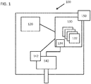
- FIG. 1 is a schematic of an exemplary electric tool 100 including a control system 130, in accordance with various embodiments.
- Electric current may be supplied by a power supply 120, such as an A/C source from a wall socket or generator, or a battery power supply.
- the electrical current may be controlled and/or modulated by the control system 130.
- the electrical current controlled by the control system 130 may in turn be supplied to an electric motor 140, for example to provide the energy necessary to rotate the electric motor 140, and may further be controlled by a trigger or control switch 150 coupled to the control system 130.
- the control system 130 may determine how much current to supply to the electric motor 140, for example when running in continuous power mode and/or boost power mode.
- the various components of power supply 120, control system 130 and its associated components, electric motor 140, and other sensors or indicators such as load sensor 142, sensors 132, and control switch 150 may comprise an electrical path of components. These components in the electrical path and their respective current handling capacities may define the system thermal limit, as described above.
- control system 130 may be configured to increase (for example boost) the supply of electric current to the electric motor 140 from the power supply 120 when the electric motor 140 encounters a load and thermal parameters of the various associated electrical components of tool 100 are within a safe margin to allow for the application of the boost power mode.
- increase for example boost
- Control system 130 may be implemented as one or more electronic controllers, such as a microprocessor, a microcontroller, discrete circuitry, a combination of the foregoing, or some other device offering similar functionality. Some embodiments may implement some or all of control system 130 using a field-programmable gate array (FPGA), application-specific integrated circuit (ASIC), or another similar technology. In some embodiments, control system 130 may include a computer-readable medium such as a memory storage unit containing instructions capable of being executed by a processing unit that is part of control system 130. Control system 130, as depicted in Figure 1 , should be understood as a logical block, and may, in various embodiments, may be implemented by one or more discrete modules.
- FPGA field-programmable gate array
- ASIC application-specific integrated circuit
- Control system 130 may implement one or more actions of the operational method 200 described below with respect to Figure 2 . These actions may be implemented with respect to a given embodiment of control system 130. For example, where control system 130 includes a microprocessor or microcontroller, method 200 may be implemented in whole or in part using instructions capable of being executed by the microprocessor or microcontroller. For another example, where control system 130 is implemented using discrete components or using transistor-transistor logic (TTL), such components may be arranged to implement some or all actions of method 200. For still another example, control system 130 may use a combination of the foregoing, with some actions of method 200 implemented using a microcontroller and other actions implemented using discrete components.
- TTL transistor-transistor logic
- control system 130 may include one or more sensors 132 arranged and configured to monitor and/or assess various parameters of the system.
- sensor 132 may be a temperature-sensing device such as a thermistor, thermocouple, or similarly suitable temperature sensor.
- sensor 132 may be a current sensor.
- Multiple sensors 132 may be employed to monitor various discrete components of tool 100, with the multiple sensors 132 being of the same or different types.
- control system 130 may include a sensor 132 to monitor the temperature of the battery of power supply 120, another sensor 132 to monitor the current from power supply 120, a sensor 132 to monitor the temperature of an electronic speed control (ESC) 134, and a sensor 132 to monitor the temperature of electric motor 140.
- ESC electronic speed control
- sensor 132 to monitor the temperature of electric motor 140.
- yet another example may include a sensor 132 to monitor ambient temperature.
- Electric motor 140 may be any motor suitable to operate within tool 100 for tool 100's intended use. Suitable motor types may include induction motors, universal motors, brushed motors, brushless motors, or any other type now know or later developed that is useful to the intended purposes of tool 100. Electric motor 140 may be supplied power by ESC 134, which may be implemented using technology suitable for delivering and modulating power to electric motor 140 in a manner appropriate to the type of electric motor 140.
- the ESC 134 may be integrated into or a part of control system 130, as depicted in Figure 1 , or may be a separate, discrete component in communication or under the direction of control system 130.
- ESC 134 may be separate from control system 130 while implementing at least a part of method 200, with other actions of method 200 being implemented in whole or in part by control system 130.
- electric motor 140 may be mechanically coupled to a driven element to supply power for tool 100 to perform work.
- Load sensor 142 may be coupled to electric motor 140, control system 130, and/or a driven element of tool 100.
- load sensor 142 may be implemented as, or part of, a tool speed sensor.
- An overload situation may be detected by a reduction in tool speed that a user has not commanded, e.g. the user continues to request the same or an increasing power level via control switch 150.
- load sensor 142 may monitor the sprocket's RPMs.
- load sensor 142 may be coupled to electric motor 140, where it can measure electric motor's 140 speed.
- load sensor 142 may be coupled to the power leads to electric motor 140 and be configured to monitor the current draw of motor 140. In such a configuration, an increasing load on tool 100 may result in a rising current draw, thus indicating the state of the tool 100 loading.
- Load sensor 142 may be implemented using any technology suitable to monitor the selected measure of loading.
- load sensor 142 may be a hall effect sensor or optical detector, configured to determine rotational speed.
- load sensor 142 may be implemented as a rotary encoder.
- load sensor 142 may be implemented as an inductive coil for monitoring current draw.
- load sensor 142 may be implemented as a strain gauge or similar device for measuring deflection of a shaft or other driven component in response to loading. Other embodiments may use other suitable sensor technologies now known or later developed.
- load sensor 142 may be a part of control system 130.
- load sensor 142 may be a part of or comprise a sensor 132, as discussed above.
- load sensor 142 may be a part of ESC 134.
- trigger or control switch 150 may be implemented as a simple on/off toggle where the tool is expected to generally operate at a fixed or constant speed.
- Other embodiments may implement control switch 150 as a variable trigger, allowing a user to modulate the power delivered by tool 100 between off and full speed.
- Variable triggers may be implemented with a variety of devices, depending upon the nature of control system 130.
- control switch 150 may be a potentiometer to vary the voltage potential or flow of current, or a position encoder, where the sensed position may translated to a corresponding current, speed, or power level by control system 130.
- control switch 150 may incorporate a step, toggle, or a second switch to enable a user to manually switch tool 100 from continuous power to a boost power mode, as will be described herein.
- FIG 2 is a flowchart showing an exemplary operational method 200 that may be implemented in whole or in part by a control system 130 depicted in Figure 1 and/or some other component of tool 100, in accordance with various embodiments herein.
- control system 130 may drive electric motor 140 in continuous power mode.
- control system 130 limits the delivery of power and current to electric motor 140 to a level that ensures that the system thermal limit, defined above as the continuous current limit the various components of the tool 100's electrical path can handle to continuously dissipate generated heat, is not exceeded.
- control system 130 may deliver a variable amount of power from zero (shut-off) up to the continuous current limit.
- Some embodiments may limit the maximum current in continuous power mode to some amount less than the actual continuous current limit of the electrical path, to provide a safety margin to prevent unintended excursions past the system thermal limit.
- Other embodiments may use sensors 132, possibly including a sensor 132 to measure ambient temperatures, to dynamically determine the continuous current limit based upon the impact of the ambient temperature on the ability of the various components to continuously dissipate heat.
- Still other embodiments may vary the continuous current limit based upon the nature of power supply 120.
- power supply 120 is implemented as a battery pack
- the state of charge and capacity of the battery pack may influence the amount of power that can be delivered.
- drawing excessive current may damage the pack, and so control system 130 may be configured to set the continuous power limit to not exceed the capabilities of the battery pack.
- the maximum delivered power in continuous power mode is less than the absolute maximum power the motor 140 is capable of running.
- the absolute maximum power the motor 140 is capable of running may be defined as the maximum current the motor 140 could draw while still turning, viz. the current draw just prior to a stall at full power. In many embodiments, this power level is above the maximum continuous power limit.
- one or more sensors coupled to the control system 130 may detect an increase in load to the motor that may be above what the electrical path components can handle at the continuous current limit, for some embodiments, or for other embodiments, above some other predetermined threshold.
- load sensor 142 may detect an increase in load to the motor that may be above what the electrical path components can handle at the continuous current limit, for some embodiments, or for other embodiments, above some other predetermined threshold.
- use of tool 100 will naturally present a fluctuating load.
- tool 100 will be capable of handling this load increase within the continuous current limit, and so an increasing load will cause control system 130 to provide more power but without exceeding the continuous current limit, or some lower threshold that may be set as described above with respect to block 210.
- method 200 proceeds to block 230 where a boost power mode may be initiated, as will be described further below with respect to the following blocks.
- this predetermined threshold may or may not be coincident with the continuous current limit or a lower limit established to provide a safety margin, as described above.
- implementing control system 130 may initiate a test routine to determine if it is safe to switch the motor 140 into boost power mode. Because boost power mode results in power (and current) being delivered through the electrical path to motor 140 that may exceed the system thermal limit, the application of boost power mode may only be initiated if the motor 140 and/or other electrical path components are running within parameters such that the motor 140 and/or other components would not be damaged by such an increase in power and associated current supplied to the motor 140. As described above, the primary limiting factor may be the capacity of the components to dissipate generated heat and the speed at which undissipated heat builds up during boost power mode. Tied to these factors is the amount of power beyond the continuous power limit that boost power mode enables, and how long boost power mode is enabled.
- Actions in block 230 may include a system check to determine if the thermal parameters are within the predetermined limits that allow for application of a boost power mode.
- An implementing control system 130 may collect measurements from one or more sensors 132 to determine a current thermal state of the various components of the electrical path and motor 140. Where sensors 132 measure temperatures, this data may be used directly. In embodiments where sensors 132 measure current flow, this data may be used to derive temperature headroom for the electrical path components.
- the control system checks whether the results of the thermal parameter check from block 230 are within normal limits, or otherwise indicate that the electrical path components have sufficient thermal headroom to accommodate a heat buildup from the excess current provided during the boost power mode. If yes, method 200 may proceed to block 250, where boost power mode is initiated. In some embodiments, whether the electrical path components have sufficient thermal headroom may be determined by a pre-established threshold. In other embodiments, whether any available or sensed thermal headroom is sufficient to allow entry into boost power mode in block 250 may depend upon the particular readings from sensors 132 in conjunction with ambient temperatures.
- readings from sensors 132 and available thermal headroom may be used not only to determine whether boost power mode may be safely entered, but also to determine the duration allowed for boost power mode and/or the amount of additional power available under boost power mode.
- a thermal headroom of 0 to 150°C may correspond to power increases of 0 to 200% over continuous limit for durations of 0 to 10 seconds.
- control system 130 may discontinue or reduce power to the electric motor 140. This may prevent and/or reduce the possibility of motor and/or system damage, for example from overload or shorting out.
- Control system 130 may remain in block 240 and shut down to allow tool 100 to dissipate built-up heat. In various embodiments, control system 130 may remain shut down in block 240 until a predetermined timer elapses and/or sensors 132 indicate that the tool 100's thermal conditions have returned to an operable condition. In some embodiments, control system 130 may additionally or alternatively require the tool user to first release trigger 150 before allowing the tool 100 to restart.
- control system 130 may reenter continuous power mode in block 210, instead of block 240.
- control system 130 may be configured to determine whether to proceed to block 240, and shut down, or reenter block 210, and continuous power mode, based upon whether sensors 132 indicate that tool 100 is approaching an overload condition.
- control system 130 may initiate a controlled boost power mode at block 250.
- control system 130 may be configured to not switch back into continuous power mode for a predetermined period of time, for example, a time selected from a range from 100ms to 10 seconds. This delay or lock-out may prevent or reduce unnecessary or frequent cycling between modes.
- the control system 130 may also be configured to prevent re-entering boost mode from continuous mode for a predetermined period of time, for example, 100ms to 10s.
- the length of the predetermined time may be limited or otherwise upon a number of factors. Such factors may include: the amount of thermal headroom determined from blocks 230 and 235, where a greater amount of headroom would allow for a greater predetermined time; and, the degree to which the available power in boost power mode exceeds the available power in continuous power mode, where a greater boost power may require a shorter predetermined time.
- the various factors may be utilized by a control system 130 to determine the predetermined time.
- the predetermined time may be determined by control system 130 each time boost power mode is entered in block 240 on the basis of the various factors.
- the method 200 may include, when it is determined that the load has exceeded the pre-determined threshold in block 220 for entering boost power mode, delaying initiating boost power mode unless the load has crossed the threshold for a specified period of time, for example, a time selected from a range from 100ms to 10 seconds.
- This delay may be useful to prevent tool 100 from entering boost power mode for very brief transient load fluctuations that quickly subside, and entering boost power mode would be of limited benefit.
- Such a delay may also help to keep boost power mode available for more substantial transient load spikes where boost power mode would prove beneficial, where engaging boost power mode would otherwise result in a delay or lockout of entering boost power mode upon return to continuous power mode.
- Such a predetermined period of time may even be employed in embodiments where boost power mode is otherwise locked out using sensors such as a temperature sensor.
- Other embodiments may utilize feedback, such as a temperature sensor, to determine when the components have cooled sufficiently.
- feedback such as a temperature sensor
- This later approach may be particularly useful when tool 100 may be used in environments where temperatures may appreciably vary, as the components of tool 100 may require a greater or lesser amount of time to dissipate built up heat depending upon ambient temperatures. For example, an electric chain saw may find use any time of the year.
- components of tool 100 When operated on a hot summer day, components of tool 100 may require longer to dissipate heat following boost mode compared to operation during the winter. In winter, the denser cold air can more efficiently dissipate heat, and so allow control system 130 to re-enable boost mode sooner than in summer weather.
- the control system 130 may supply electric current to the electric motor 140 at a level greater than the continuous operation level so as to attempt to avoid a stall situation and/or power through a high transient load, such as a small section of particularly dense vegetation (as may be encountered by a hedge trimmer or string trimmer). Because the electric motor 140 may only be run in boost power mode when deemed necessary, more efficient use of power is also made. Furthermore, the electric power tool 100 may generally run quieter, as the generally noisier boost power mode may only be used when necessary. In some embodiments, the electric power tool 100 may be a battery-operated power tool, where the power supply 120 comprises a battery. In such a case, the need to conserve electricity may be of great importance.
- a boost power mode could be applied to tools where the power supply is an input for electric current from an external source (such as alternating current electricity) in order to make more efficient use of the electric power provided. Additionally or alternatively, a boost power mode could allow tool 100 to briefly draw power in excess of the rated capacity of a circuit to which tool 100 is connected.
- control system 130 may be configured to automatically switch between the boost power mode when there is an indication of increased motor load and the continuous power mode when there is an indication of decreased motor load.
- the control system 130 may automatically switch from the continuous power mode to the boost power mode when the load sensor 142 indicates that the load exceeds the predetermined threshold discussed above with respect to block 220, and possibly also to switch from the boost power mode to the continuous power mode when the load sensor 142 indicates the load is below a second predetermined threshold, as will be discussed in greater detail below.
- the first and second thresholds are different. In other embodiments, the first and second thresholds are the same.
- control system 130 may allow a user to manually switch to the boost power mode, or, in other embodiments, may allow the user to choose between manual and the automatic switching described above.
- Manual mode may be preferable to users who want greater control over power consumption, for example, to prolong battery life or prevent repeated circuit breaker trips if tool 100 is plugged into a circuit that is shared with other appliances or tools.
- control system 130 may enable power delivery in excess of the continuous current limit, within the predetermined and/or sensed system thermal limits.
- control system 130 may start a timer, either predetermined or set based upon sensed thermal headroom, to determine how long boost power may be safely delivered without risking damage to components of tool 100.
- control system 130 may rely solely upon feedback from one or more sensors 132 to determine the thermal condition of tool 100 and prevent exceeding the maximum thermal limits of any of the components of the electrical path.
- boost power mode may be useful if the excess load is fluctuating or only minimally above what tool 100 can handle in continuous power mode, as boost power mode may be safely enabled for a longer period of time in such conditions, as opposed to when the load is substantially beyond what tool 100 can handle in continuous power mode.
- control system 130 may monitor the motor load, such as via load sensor 142.
- the load may be sensed as described above with respect to load sensor 142.
- control system 130 may revert back to block 210, and reenter continuous power mode.
- Some embodiments may also utilize feedback from sensors 132 to determine if returning to block 210 and continuous power mode is feasible.
- Other embodiments may utilize the predetermined threshold for entering boost power mode described above with respect to block 220. Still other embodiments may utilize a second predetermined threshold that is greater or lesser than the predetermined threshold for entering boost power mode.
- control system 130 may employ a lock-out from boost power mode for a predetermined length of time and/or until sensed conditions indicate sufficient thermal headroom is present.
- control system 130 may jump back to block 240 and cut power/stall the motor 140. In other embodiments, control system 130 may proceed to block 260, and enter cutback mode.
- control system 130 may set a cutback power level, which may be a maximum power level that is below the continuous power level. Because such a reduced power level is below the continuous power level, a reduced current flows through the electrical path components. As explained above, a reduced current from the current in continuous power mode may result in a reduction in the amount of generated heat that must be dissipated, and assist tool 100 in dissipating the stored heat resulting from boost power mode while still enabling tool 100 to continue operation, without entering block 240, possibly shutting down tool 100 and/or requiring the user to release trigger 150 to continue work.
- a cutback power level which may be a maximum power level that is below the continuous power level. Because such a reduced power level is below the continuous power level, a reduced current flows through the electrical path components. As explained above, a reduced current from the current in continuous power mode may result in a reduction in the amount of generated heat that must be dissipated, and assist tool 100 in dissipating the stored heat resulting from boost power mode while still enabling tool
- the cutback power level may be a predetermined level in some embodiments, or in other embodiments may be determined dynamically by control system 130 based upon feedback from sensors 132. In embodiments implementing the later approach, for example, the cutback power level may be set lower in instances where the electrical path components are substantially at their maximum thermal limits, and incrementally higher if there is still some remaining thermal headroom.
- control system 130 While in cutback power mode, control system 130 may continue to monitor the tool load in block 265, such as via load sensor 142. If the load decreases, control system 130 may revert to continuous power mode in block 210. However, if the load does not decrease, control system 130 may proceed to shut down in block 240, as described above. As with boost power mode, in some embodiments control system 130 may allow tool 100 to remain in cutback power mode for a predetermined length of time without the load decreasing before proceeding to block 240. In other embodiments, control system 130 may rely upon feedback from sensors 132 to determine if sufficient heat has dissipated in cutback mode to allow tool 100 to revert to continuous power mode, or if the tool needs to proceed to shut down in block 240.
- embodiments implementing cutback power mode may allow a user to continue to use tool 100 even after an overload condition without needing to shut down tool 100 or for the user to release trigger 150 and wait some time for tool 100 to cool down.
- method 200 may allow a user of the hedge trimmer to power through brief patches of thicker shrubbery. If the user pushes the tool to the limit of boost power mode, tool 100 may revert to the reduced-power cutback power mode, allowing the user to reduce load without releasing the trigger, or keep working while signaling the user to ease up cutting to allow the tool to cool. If the user keeps up aggressively loading the tool even in cutback power mode, then tool 100 may need to shut down to avoid damage.
- Figure 3 is an example trace of the current supplied by a control system 130 implementing method 200 to a motor 140, in accordance with various embodiments.
- a continuous power limit 302 can be set, for example at about 15.0 Amps.
- the amperage may be increased above the continuous power limit 302, to a boost limit 304 as control system 130 enters boost power mode, for a limited period of time as described above.
- the boost limit 304 may be selected to be approximately 19 Amps, and the time limit may be 2.5 seconds.
- the amperage is reduced to a cutback level 306 which is below the continuous power level 302, to allow the components of the system to recover and/or cool.
- the cutback level 306 may be selected to be approximately 8 Amps. If the load does not decrease or the control system 130 otherwise enters block 240 and shuts down, the current is reduced to the stall level 308, shown as 0 Amps, or no current flowing. Control system 130 may be configured to enter shut down if the load does not decrease after a predetermined time period, for example, approximately 1 second. As with the other parameters, this time period may vary depending upon the specifics of a given implementation.
Landscapes
- Life Sciences & Earth Sciences (AREA)
- Engineering & Computer Science (AREA)
- Biodiversity & Conservation Biology (AREA)
- Ecology (AREA)
- Forests & Forestry (AREA)
- Environmental Sciences (AREA)
- Power Engineering (AREA)
- Mechanical Engineering (AREA)
- Portable Power Tools In General (AREA)
- Control Of Ac Motors In General (AREA)
- Control Of Electric Motors In General (AREA)
Description
- Embodiments herein relate to the field of electric tools, and, more specifically, to devices, methods, and systems for electric motors to automatically adjust their power output in response to load.
- Hand held electric power tools, such as string trimmers, hedge trimmers, chain saws, and pole saws, include an electric motor. Using a hedge trimmer as an example, these tools are ideal for cutting large areas of thin branches and stems. However when encountering larger branches, the electric motor of the hedge trimmer may experience a stall as the larger branches become lodged in the cutting blades of the hedge trimmer.
EP2685627 discloses a power tool including a voltage increasing circuit connected to a power supply to regulate power supplied to a load.
US 2013/020102 discloses A battery-operated power tool comprising a working element, a motor arranged to drive the working element and a controller arranged to control the speed at which the motor drives the working element, in which there is provided a sensor for at least one factor, typically the pressure which the user is applying the power tool, indicative of the efficiency with which the power tool is being operated. The controller is arranged to vary the speed at which the motor drives the working element should the factor indicate that the power tool is being operated in a sub-optimal manner.
WO2010098149 andJP5337274
CN206211869 discloses a power supply changeover device for an electric tool.US8076873 discloses hybrid power equipment comprising a user-selectable power selection switch for switching between DC or AC power, a boost and conserve feature for increasing speed of the working elements as necessary, and a motor or a plurality of motors for moving working elements. Power supply and control systems allow the user to select operation of the plurality motors or dual coil commutators in either series or parallel configuration depending on the power source. - Embodiments will be readily understood by the following detailed description in conjunction with the accompanying drawings and the appended claims. Embodiments are illustrated by way of example and not by way of limitation in the figures of the accompanying drawings.
-
Figure 1 is a schematic of an electric power tool including an exemplary control system, in accordance with various embodiments; -
Figure 2 is a flowchart showing a method for power modulating control of a motor that may be implemented by a control system of the electric power tool ofFigure 1 , in accordance with various embodiments; and -
Figure 3 is a trace of current supplied to an electric motor by a control system implementing the method depicted inFigure 2 , in accordance with various embodiments. - In the following detailed description, reference is made to the accompanying drawings, which form a part hereof, and in which are shown by way of illustration embodiments that may be practiced. It is to be understood that other embodiments may be utilized and structural or logical changes may be made without departing from the scope of the claims. Therefore, the following detailed description is not to be taken in a limiting sense, and the scope of embodiments is defined by the appended claims.
- Various operations may be described as multiple discrete operations in turn, in a manner that may be helpful in understanding embodiments; however, the order of description should not be construed to imply that these operations are order dependent.
- The description may use perspective-based descriptions such as up/down, back/front, and top/bottom. Such descriptions are merely used to facilitate the discussion and are not intended to restrict the application of disclosed embodiments.
- The terms "coupled" and "connected," along with their derivatives, may be used. It should be understood that these terms are not intended as synonyms for each other. Rather, in particular embodiments, "connected" may be used to indicate that two or more elements are in direct physical contact with each other. "Coupled" may mean that two or more elements are in direct physical contact. However, "coupled" may also mean that two or more elements are not in direct contact with each other, but yet still cooperate or interact with each other.
- For the purposes of the description, a phrase in the form "A/B" or in the form "A and/or B" means (A), (B), or (A and B). For the purposes of the description, a phrase in the form "at least one of A, B, and C" means (A), (B), (C), (A and B), (A and C), (B and C), or (A, B and C). For the purposes of the description, a phrase in the form "(A)B" means (B) or (AB) that is, A is an optional element.
- The description may use the terms "embodiment" or "embodiments," which may each refer to one or more of the same or different embodiments. Furthermore, the terms "comprising," "including," "having," and the like, as used with respect to embodiments, are synonymous, and are generally intended as "open" terms (e.g., the term "including" should be interpreted as "including but not limited to," the term "having" should be interpreted as "having at least," the term "includes" should be interpreted as "includes but is not limited to," etc.).
- With respect to the use of any plural and/or singular terms herein, those having skill in the art can translate from the plural to the singular and/or from the singular to the plural as is appropriate to the context and/or application. The various singular/plural permutations may be expressly set forth herein for sake of clarity.
- Electric tools that may implement embodiments disclosed herein, such as A/C or battery operated power tools, typically include a power supply, such as power cord or a battery, an electric motor controlled by a control system, and a driven element such as a blade, driven by the electric motor. They are typically lighter and quieter than their gas powered counterparts and are thus widely used by the home consumer. More recently, the electric versions of handheld landscaping and/or arborist tools are being adopted by commercial users. One of the hurdles facing their adoption is the peak power output that may be needed in commercial operations, such as commercial landscaping operations.
- As used herein, "power" may be understood by its accepted electrical definition of voltage times current. Accordingly, for a given tool voltage, e.g. 18-60VDC for many cordless battery-operated tools, increasing power for a given voltage results in increased current. To the extent that "power" and "current" are used interchangeably herein, it should be understood that the terms are expressed with respect to a given reference voltage, so that increasing power directly correlates to an increasing current.
- The electronic components of the electric tools, commonly including batteries or power supplies, motors, motor controllers, switches, and conductors such as wires or leads, have limits to the amount of power that each can continuously deliver. Electric current flowing through a component typically generates heat, with the amount of heat generated in a component corresponding to the amount of current flowing through the component. Accordingly, increasing power increases the current through a component (assuming the operating voltage remains approximately constant), which can result in a corresponding increase in the amount of heat generated by the component. To avoid component damage and/or failure, this heat must be dissipated prior to reaching the component's thermal limits. Because a given component may have a limit on the amount of heat that it can dissipate continuously, this continuous dissipation limit effectively determines the component's continuous current limit, and by extension, continuous power limit.
- It may be understood from the foregoing that passing a current through a component that exceeds its continuous current limit may result in heat being generated faster than can be dissipated. This in turn may result in component temperature rising and, if the excess current does not abate in time, the component exceeding its thermal limits. It may further be understood that the greater the current excursion above the component's continuous current limit, the faster the component temperature will rise.
- A given tool may present a chain of electrical components, such as a battery or power supply, which feeds to a controller, which in turn may pass some current through a trigger or actuator and/or may control or pass current through a motor. Conductors such as leads or wires, themselves components, may tie these components together. Each component may have its own continuous current limit that may differ from other components. As each component may impact the amount of current flowing through other components, the entire chain of electrical components may be considered to have a system continuous current limit. This system continuous current limit may also be characterized as a system thermal limit (also simply referred to as a "system thermal").
- To safeguard against damage, modern electric tools may be equipped with control electronics that limit the amount of continuous power that the tool delivers to ensure the controlled electronic components stay within the system thermal limit. In the context a motor-driven electric tool or implement, the amount of power required, and thus current draw, by an electric motor increases with motor load. A severe overload, such as a jammed tool, may result in a complete motor stall. A motor stall can effectively act as a short circuit, drawing relatively immense amounts of current through the motor and associated components and potentially causing damage within a matter of seconds. Thus, the control electronics may be configured to detect a motor stall, such as may occur if a tool is jammed, e.g., when a hedge trimmer is unable to cut through a thick branch, or a chainsaw binds while sawing a log. The resulting partially severed branch or pinched kerf may prevent further movement of the trimmer bar or saw chain, respectively, and consequently, the mechanically linked motor. The control electronics, such as an electronic speed controller (ESC), may be configured to detect dramatic spikes in current draw indicative of a motor stall, and completely shut current flow to prevent damage to the ESC and motor.
- As may be appreciated from the foregoing discussion, electronic components may be able to handle power levels that exceed the continuous current limit provided the higher power and associated excess heat build-up is discontinued prior to damage occurring. The duration of such higher power levels can depend upon the extent to which the power exceeds the continuous current limit, along with the thermal limits of the components in question. Bursts of such higher power levels, so long as discontinued before system thermal limits are reached, may be useful in electric tools for helping to power through jobs where occasional transient high loads occur that may otherwise cause the tool to stall if only operated at a power level at or below the continuous current limit. For example, a tool may have a continuous current limit in the 5 to 50 amp range, with the tool components designed to handle these currents continuously during operation. The tool may further be able to handle bursts of current from 20% to 200% above the continuous current limit for 10 seconds (with a burst closer to 20% over continuous) to 100 milliseconds (when the burst approaches 200% over continuous) without significantly impacting system thermal limits.
- Thus, disclosed are embodiments, systems such as electronic control systems, and devices incorporating the same that assess the entire system of an electric tool to determine how much excess power capacity or headroom is available. If sufficient power headroom is available, the control system can route power in excess of the continuous current limit to an electric motor, for example to overcome a potential stall situation presented by a transient load. The control system determines the presence of power headroom by testing whether the system thermals will allow for such a brief "boost" of additional power. If the thermal parameters are within acceptable ranges, the control system provides the additional current for a controlled period of time. In embodiments, this additional power may help hedge trimmers get through large branches, help chainsaws avoid stalls, and even improve trigger response by allowing for motor accelerations that would otherwise be impossible to achieve within a continuous power limit.
-
Figure 1 is a schematic of an exemplaryelectric tool 100 including acontrol system 130, in accordance with various embodiments. Electric current may be supplied by apower supply 120, such as an A/C source from a wall socket or generator, or a battery power supply. The electrical current may be controlled and/or modulated by thecontrol system 130. The electrical current controlled by thecontrol system 130 may in turn be supplied to anelectric motor 140, for example to provide the energy necessary to rotate theelectric motor 140, and may further be controlled by a trigger or controlswitch 150 coupled to thecontrol system 130. Thecontrol system 130 may determine how much current to supply to theelectric motor 140, for example when running in continuous power mode and/or boost power mode. The various components ofpower supply 120,control system 130 and its associated components,electric motor 140, and other sensors or indicators such asload sensor 142,sensors 132, and controlswitch 150 may comprise an electrical path of components. These components in the electrical path and their respective current handling capacities may define the system thermal limit, as described above. - As will be described in greater detail herein with respect to
Figures 2 and3 ,control system 130 may be configured to increase (for example boost) the supply of electric current to theelectric motor 140 from thepower supply 120 when theelectric motor 140 encounters a load and thermal parameters of the various associated electrical components oftool 100 are within a safe margin to allow for the application of the boost power mode. -
Control system 130 may be implemented as one or more electronic controllers, such as a microprocessor, a microcontroller, discrete circuitry, a combination of the foregoing, or some other device offering similar functionality. Some embodiments may implement some or all ofcontrol system 130 using a field-programmable gate array (FPGA), application-specific integrated circuit (ASIC), or another similar technology. In some embodiments,control system 130 may include a computer-readable medium such as a memory storage unit containing instructions capable of being executed by a processing unit that is part ofcontrol system 130.Control system 130, as depicted inFigure 1 , should be understood as a logical block, and may, in various embodiments, may be implemented by one or more discrete modules. -
Control system 130 may implement one or more actions of theoperational method 200 described below with respect toFigure 2 . These actions may be implemented with respect to a given embodiment ofcontrol system 130. For example, wherecontrol system 130 includes a microprocessor or microcontroller,method 200 may be implemented in whole or in part using instructions capable of being executed by the microprocessor or microcontroller. For another example, wherecontrol system 130 is implemented using discrete components or using transistor-transistor logic (TTL), such components may be arranged to implement some or all actions ofmethod 200. For still another example,control system 130 may use a combination of the foregoing, with some actions ofmethod 200 implemented using a microcontroller and other actions implemented using discrete components. - In implementing the various actions of
method 200,control system 130 may include one ormore sensors 132 arranged and configured to monitor and/or assess various parameters of the system. In some embodiments,sensor 132 may be a temperature-sensing device such as a thermistor, thermocouple, or similarly suitable temperature sensor. In other embodiments, such as where a correlation between current amount and component temperature is established,sensor 132 may be a current sensor.Multiple sensors 132 may be employed to monitor various discrete components oftool 100, with themultiple sensors 132 being of the same or different types. For example, in an embodiment wheretool 100 is battery-powered,control system 130 may include asensor 132 to monitor the temperature of the battery ofpower supply 120, anothersensor 132 to monitor the current frompower supply 120, asensor 132 to monitor the temperature of an electronic speed control (ESC) 134, and asensor 132 to monitor the temperature ofelectric motor 140. Depending upon the nature oftool 100, the possible environments of its intended use, and the thermal limits of the various components, yet another example may include asensor 132 to monitor ambient temperature. -
Electric motor 140 may be any motor suitable to operate withintool 100 fortool 100's intended use. Suitable motor types may include induction motors, universal motors, brushed motors, brushless motors, or any other type now know or later developed that is useful to the intended purposes oftool 100.Electric motor 140 may be supplied power byESC 134, which may be implemented using technology suitable for delivering and modulating power toelectric motor 140 in a manner appropriate to the type ofelectric motor 140. TheESC 134 may be integrated into or a part ofcontrol system 130, as depicted inFigure 1 , or may be a separate, discrete component in communication or under the direction ofcontrol system 130. In some embodiments,ESC 134 may be separate fromcontrol system 130 while implementing at least a part ofmethod 200, with other actions ofmethod 200 being implemented in whole or in part bycontrol system 130. In various embodiments,electric motor 140 may be mechanically coupled to a driven element to supply power fortool 100 to perform work. -
Load sensor 142 may be coupled toelectric motor 140,control system 130, and/or a driven element oftool 100. In one possible embodiment,load sensor 142 may be implemented as, or part of, a tool speed sensor. An overload situation may be detected by a reduction in tool speed that a user has not commanded, e.g. the user continues to request the same or an increasing power level viacontrol switch 150. For example, wheretool 100 is a chainsaw andload sensor 142 is coupled to a driven element such as a chain drive sprocket,load sensor 142 may monitor the sprocket's RPMs. The user may request a target motor RPM in the 100 to 10000 RPM range, but due to external loading combined with continuous current limits, the controller may only be able to maintain a motor speed less than 95% of the target speed. Alternatively,load sensor 142 may be coupled toelectric motor 140, where it can measure electric motor's 140 speed. In another example,load sensor 142 may be coupled to the power leads toelectric motor 140 and be configured to monitor the current draw ofmotor 140. In such a configuration, an increasing load ontool 100 may result in a rising current draw, thus indicating the state of thetool 100 loading. -
Load sensor 142 may be implemented using any technology suitable to monitor the selected measure of loading. For example,load sensor 142 may be a hall effect sensor or optical detector, configured to determine rotational speed. In another example,load sensor 142 may be implemented as a rotary encoder. In yet another example,load sensor 142 may be implemented as an inductive coil for monitoring current draw. In still another example,load sensor 142 may be implemented as a strain gauge or similar device for measuring deflection of a shaft or other driven component in response to loading. Other embodiments may use other suitable sensor technologies now known or later developed. - Although depicted as being disposed about
electric motor 140, in some embodiments,load sensor 142 may be a part ofcontrol system 130. In particular,load sensor 142 may be a part of or comprise asensor 132, as discussed above. In other embodiments,load sensor 142 may be a part ofESC 134. - Depending upon the nature of
tool 100, trigger or controlswitch 150 may be implemented as a simple on/off toggle where the tool is expected to generally operate at a fixed or constant speed. Other embodiments may implementcontrol switch 150 as a variable trigger, allowing a user to modulate the power delivered bytool 100 between off and full speed. Variable triggers may be implemented with a variety of devices, depending upon the nature ofcontrol system 130. For example,control switch 150 may be a potentiometer to vary the voltage potential or flow of current, or a position encoder, where the sensed position may translated to a corresponding current, speed, or power level bycontrol system 130. In still other embodiments,control switch 150 may incorporate a step, toggle, or a second switch to enable a user to manually switchtool 100 from continuous power to a boost power mode, as will be described herein. -
Figure 2 is a flowchart showing an exemplaryoperational method 200 that may be implemented in whole or in part by acontrol system 130 depicted inFigure 1 and/or some other component oftool 100, in accordance with various embodiments herein. - At
block 210, following activation oftool 100,control system 130 may driveelectric motor 140 in continuous power mode. In continuous power mode,control system 130 limits the delivery of power and current toelectric motor 140 to a level that ensures that the system thermal limit, defined above as the continuous current limit the various components of thetool 100's electrical path can handle to continuously dissipate generated heat, is not exceeded. Depending on the nature and use or loading oftool 100,control system 130 may deliver a variable amount of power from zero (shut-off) up to the continuous current limit. Some embodiments, such as wheretool 100 may be used in an environment with extreme temperature ranges, may limit the maximum current in continuous power mode to some amount less than the actual continuous current limit of the electrical path, to provide a safety margin to prevent unintended excursions past the system thermal limit. Other embodiments may usesensors 132, possibly including asensor 132 to measure ambient temperatures, to dynamically determine the continuous current limit based upon the impact of the ambient temperature on the ability of the various components to continuously dissipate heat. - Still other embodiments may vary the continuous current limit based upon the nature of
power supply 120. For example, wherepower supply 120 is implemented as a battery pack, the state of charge and capacity of the battery pack may influence the amount of power that can be delivered. Depending upon the nature of the battery pack, drawing excessive current may damage the pack, and so controlsystem 130 may be configured to set the continuous power limit to not exceed the capabilities of the battery pack. - As will be recognized by a person skilled in the relevant art, the maximum delivered power in continuous power mode is less than the absolute maximum power the
motor 140 is capable of running. In one respect, the absolute maximum power themotor 140 is capable of running may be defined as the maximum current themotor 140 could draw while still turning, viz. the current draw just prior to a stall at full power. In many embodiments, this power level is above the maximum continuous power limit. - At
block 220, one or more sensors, such asload sensor 142, coupled to thecontrol system 130 may detect an increase in load to the motor that may be above what the electrical path components can handle at the continuous current limit, for some embodiments, or for other embodiments, above some other predetermined threshold. In embodiments and depending upon the nature oftool 100, use oftool 100 will naturally present a fluctuating load. In many cases,tool 100 will be capable of handling this load increase within the continuous current limit, and so an increasing load will causecontrol system 130 to provide more power but without exceeding the continuous current limit, or some lower threshold that may be set as described above with respect to block 210. - If the load increases to the point where
control system 130 cannot provide sufficient power to handle the load without exceeding the continuous current limit or some lower predetermined threshold,method 200 proceeds to block 230 where a boost power mode may be initiated, as will be described further below with respect to the following blocks. In embodiments, this predetermined threshold may or may not be coincident with the continuous current limit or a lower limit established to provide a safety margin, as described above. - At
block 230, implementingcontrol system 130 may initiate a test routine to determine if it is safe to switch themotor 140 into boost power mode. Because boost power mode results in power (and current) being delivered through the electrical path tomotor 140 that may exceed the system thermal limit, the application of boost power mode may only be initiated if themotor 140 and/or other electrical path components are running within parameters such that themotor 140 and/or other components would not be damaged by such an increase in power and associated current supplied to themotor 140. As described above, the primary limiting factor may be the capacity of the components to dissipate generated heat and the speed at which undissipated heat builds up during boost power mode. Tied to these factors is the amount of power beyond the continuous power limit that boost power mode enables, and how long boost power mode is enabled. - Actions in
block 230 may include a system check to determine if the thermal parameters are within the predetermined limits that allow for application of a boost power mode. An implementingcontrol system 130 may collect measurements from one ormore sensors 132 to determine a current thermal state of the various components of the electrical path andmotor 140. Wheresensors 132 measure temperatures, this data may be used directly. In embodiments wheresensors 132 measure current flow, this data may be used to derive temperature headroom for the electrical path components. - At
block 235, the control system checks whether the results of the thermal parameter check fromblock 230 are within normal limits, or otherwise indicate that the electrical path components have sufficient thermal headroom to accommodate a heat buildup from the excess current provided during the boost power mode. If yes,method 200 may proceed to block 250, where boost power mode is initiated. In some embodiments, whether the electrical path components have sufficient thermal headroom may be determined by a pre-established threshold. In other embodiments, whether any available or sensed thermal headroom is sufficient to allow entry into boost power mode inblock 250 may depend upon the particular readings fromsensors 132 in conjunction with ambient temperatures. In still other embodiments, readings fromsensors 132 and available thermal headroom may be used not only to determine whether boost power mode may be safely entered, but also to determine the duration allowed for boost power mode and/or the amount of additional power available under boost power mode. For example, a thermal headroom of 0 to 150°C may correspond to power increases of 0 to 200% over continuous limit for durations of 0 to 10 seconds. - If the results of
block 235 indicate that there is insufficient thermal headroom to proceed to block 250,method 200 may proceed to block 240 in some embodiments. Inblock 240, thecontrol system 130 may discontinue or reduce power to theelectric motor 140. This may prevent and/or reduce the possibility of motor and/or system damage, for example from overload or shorting out.Control system 130 may remain inblock 240 and shut down to allowtool 100 to dissipate built-up heat. In various embodiments,control system 130 may remain shut down inblock 240 until a predetermined timer elapses and/orsensors 132 indicate that thetool 100's thermal conditions have returned to an operable condition. In some embodiments,control system 130 may additionally or alternatively require the tool user tofirst release trigger 150 before allowing thetool 100 to restart. - In other embodiments and/or possibly depending upon the amount of thermal headroom determined in
block 230,control system 130 may reenter continuous power mode inblock 210, instead ofblock 240. For example,control system 130 may be configured to determine whether to proceed to block 240, and shut down, or reenterblock 210, and continuous power mode, based upon whethersensors 132 indicate thattool 100 is approaching an overload condition. - If the results of the tests of
blocks control system 130 may initiate a controlled boost power mode atblock 250. In some embodiments, after switching from the continuous power mode to the boost power mode,control system 130 may be configured to not switch back into continuous power mode for a predetermined period of time, for example, a time selected from a range from 100ms to 10 seconds. This delay or lock-out may prevent or reduce unnecessary or frequent cycling between modes. Thecontrol system 130 may also be configured to prevent re-entering boost mode from continuous mode for a predetermined period of time, for example, 100ms to 10s. - It will be appreciated that, in various embodiments, the length of the predetermined time may be limited or otherwise upon a number of factors. Such factors may include: the amount of thermal headroom determined from
blocks control system 130 to determine the predetermined time. In still other embodiments, the predetermined time may be determined bycontrol system 130 each time boost power mode is entered inblock 240 on the basis of the various factors. - Additionally or alternatively, the
method 200 may include, when it is determined that the load has exceeded the pre-determined threshold inblock 220 for entering boost power mode, delaying initiating boost power mode unless the load has crossed the threshold for a specified period of time, for example, a time selected from a range from 100ms to 10 seconds. This delay may be useful to preventtool 100 from entering boost power mode for very brief transient load fluctuations that quickly subside, and entering boost power mode would be of limited benefit. Such a delay may also help to keep boost power mode available for more substantial transient load spikes where boost power mode would prove beneficial, where engaging boost power mode would otherwise result in a delay or lockout of entering boost power mode upon return to continuous power mode. Such a predetermined period of time may even be employed in embodiments where boost power mode is otherwise locked out using sensors such as a temperature sensor. - Other embodiments may utilize feedback, such as a temperature sensor, to determine when the components have cooled sufficiently. This later approach may be particularly useful when
tool 100 may be used in environments where temperatures may appreciably vary, as the components oftool 100 may require a greater or lesser amount of time to dissipate built up heat depending upon ambient temperatures. For example, an electric chain saw may find use any time of the year. When operated on a hot summer day, components oftool 100 may require longer to dissipate heat following boost mode compared to operation during the winter. In winter, the denser cold air can more efficiently dissipate heat, and so allowcontrol system 130 to re-enable boost mode sooner than in summer weather. - As described above, in the boost power mode, the
control system 130 may supply electric current to theelectric motor 140 at a level greater than the continuous operation level so as to attempt to avoid a stall situation and/or power through a high transient load, such as a small section of particularly dense vegetation (as may be encountered by a hedge trimmer or string trimmer). Because theelectric motor 140 may only be run in boost power mode when deemed necessary, more efficient use of power is also made. Furthermore, theelectric power tool 100 may generally run quieter, as the generally noisier boost power mode may only be used when necessary. In some embodiments, theelectric power tool 100 may be a battery-operated power tool, where thepower supply 120 comprises a battery. In such a case, the need to conserve electricity may be of great importance. - In other embodiments, a boost power mode could be applied to tools where the power supply is an input for electric current from an external source (such as alternating current electricity) in order to make more efficient use of the electric power provided. Additionally or alternatively, a boost power mode could allow
tool 100 to briefly draw power in excess of the rated capacity of a circuit to whichtool 100 is connected. - In various embodiments, the
control system 130 may be configured to automatically switch between the boost power mode when there is an indication of increased motor load and the continuous power mode when there is an indication of decreased motor load. Thecontrol system 130 may automatically switch from the continuous power mode to the boost power mode when theload sensor 142 indicates that the load exceeds the predetermined threshold discussed above with respect to block 220, and possibly also to switch from the boost power mode to the continuous power mode when theload sensor 142 indicates the load is below a second predetermined threshold, as will be discussed in greater detail below. In some embodiments, the first and second thresholds are different. In other embodiments, the first and second thresholds are the same. - In some embodiments,
control system 130 may allow a user to manually switch to the boost power mode, or, in other embodiments, may allow the user to choose between manual and the automatic switching described above. Manual mode may be preferable to users who want greater control over power consumption, for example, to prolong battery life or prevent repeated circuit breaker trips iftool 100 is plugged into a circuit that is shared with other appliances or tools. - Once in boost power mode in
block 250,control system 130 may enable power delivery in excess of the continuous current limit, within the predetermined and/or sensed system thermal limits. In some embodiments,control system 130 may start a timer, either predetermined or set based upon sensed thermal headroom, to determine how long boost power may be safely delivered without risking damage to components oftool 100. In other embodiments,control system 130 may rely solely upon feedback from one ormore sensors 132 to determine the thermal condition oftool 100 and prevent exceeding the maximum thermal limits of any of the components of the electrical path. Using sensed feedback while in boost power mode may be useful if the excess load is fluctuating or only minimally above whattool 100 can handle in continuous power mode, as boost power mode may be safely enabled for a longer period of time in such conditions, as opposed to when the load is substantially beyond whattool 100 can handle in continuous power mode. - While in boost power mode, in
block 255control system 130 may monitor the motor load, such as viaload sensor 142. The load may be sensed as described above with respect to loadsensor 142. In embodiments, if the load decreases to below whattool 100 can handle in continuous power mode before the predetermined timer expires and/or sensed thermal conditions indicate that boost power mode must be discontinued,control system 130 may revert back to block 210, and reenter continuous power mode. Some embodiments may also utilize feedback fromsensors 132 to determine if returning to block 210 and continuous power mode is feasible. Other embodiments may utilize the predetermined threshold for entering boost power mode described above with respect to block 220. Still other embodiments may utilize a second predetermined threshold that is greater or lesser than the predetermined threshold for entering boost power mode. When a first predetermined threshold for entering boost power mode is used in conjunction with a second, lower predetermined threshold for reentering continuous mode, a hysteresis effect may be obtained wherebycontrol system 130 helps avoid unnecessary and/or excessive toggling between continuous power mode and boost power mode when dealing with loads close to thetool 100's continuous current limit. When reverting back to block 210, as described above,control system 130 may employ a lock-out from boost power mode for a predetermined length of time and/or until sensed conditions indicate sufficient thermal headroom is present. - If, however, the load does not decrease before the predetermined timer expires and/or sensed thermal conditions indicate that boost power mode must be discontinued, in some embodiments,
control system 130 may jump back to block 240 and cut power/stall themotor 140. In other embodiments,control system 130 may proceed to block 260, and enter cutback mode. - In cutback mode of
block 260,control system 130 may set a cutback power level, which may be a maximum power level that is below the continuous power level. Because such a reduced power level is below the continuous power level, a reduced current flows through the electrical path components. As explained above, a reduced current from the current in continuous power mode may result in a reduction in the amount of generated heat that must be dissipated, and assisttool 100 in dissipating the stored heat resulting from boost power mode while still enablingtool 100 to continue operation, without enteringblock 240, possibly shutting downtool 100 and/or requiring the user to releasetrigger 150 to continue work. The cutback power level may be a predetermined level in some embodiments, or in other embodiments may be determined dynamically bycontrol system 130 based upon feedback fromsensors 132. In embodiments implementing the later approach, for example, the cutback power level may be set lower in instances where the electrical path components are substantially at their maximum thermal limits, and incrementally higher if there is still some remaining thermal headroom. - While in cutback power mode,
control system 130 may continue to monitor the tool load inblock 265, such as viaload sensor 142. If the load decreases,control system 130 may revert to continuous power mode inblock 210. However, if the load does not decrease,control system 130 may proceed to shut down inblock 240, as described above. As with boost power mode, in some embodiments controlsystem 130 may allowtool 100 to remain in cutback power mode for a predetermined length of time without the load decreasing before proceeding to block 240. In other embodiments,control system 130 may rely upon feedback fromsensors 132 to determine if sufficient heat has dissipated in cutback mode to allowtool 100 to revert to continuous power mode, or if the tool needs to proceed to shut down inblock 240. - As mentioned above, embodiments implementing cutback power mode may allow a user to continue to use
tool 100 even after an overload condition without needing to shut downtool 100 or for the user to releasetrigger 150 and wait some time fortool 100 to cool down. For example, wheremethod 200 is implemented in a hedge trimmer,method 200 may allow a user of the hedge trimmer to power through brief patches of thicker shrubbery. If the user pushes the tool to the limit of boost power mode,tool 100 may revert to the reduced-power cutback power mode, allowing the user to reduce load without releasing the trigger, or keep working while signaling the user to ease up cutting to allow the tool to cool. If the user keeps up aggressively loading the tool even in cutback power mode, thentool 100 may need to shut down to avoid damage. -
Figure 3 is an example trace of the current supplied by acontrol system 130 implementingmethod 200 to amotor 140, in accordance with various embodiments. As shown inFigure 3 , a continuous power limit 302 can be set, for example at about 15.0 Amps. The amperage may be increased above the continuous power limit 302, to aboost limit 304 ascontrol system 130 enters boost power mode, for a limited period of time as described above. In the example here, theboost limit 304 may be selected to be approximately 19 Amps, and the time limit may be 2.5 seconds. In the example shown, following boost power mode (and if the load does not decrease, as described with respect to block 255 of method 200) the amperage is reduced to acutback level 306 which is below the continuous power level 302, to allow the components of the system to recover and/or cool. In the example here, thecutback level 306 may be selected to be approximately 8 Amps. If the load does not decrease or thecontrol system 130 otherwise enters block 240 and shuts down, the current is reduced to thestall level 308, shown as 0 Amps, or no current flowing.Control system 130 may be configured to enter shut down if the load does not decrease after a predetermined time period, for example, approximately 1 second. As with the other parameters, this time period may vary depending upon the specifics of a given implementation.
Claims (12)
- An electric power tool (100), comprising:a control system (130) coupled to an electric power supply (120) and an electric motor (140), the control system (130) configured to cause an electric current to be supplied to the electric motor (140) to drive a load,
wherein:the control system (130) includes a continuous power mode wherein the electric current is supplied up to a first level and a boost power mode wherein the electric current is supplied up to a second level, the second level being greater than the first level, andthe control system (130) is to switch from the continuous power mode to the boost power mode when the control system senses an increase in the load past a predetermined threshold, and is to switch from the boost power mode to the continuous power mode when the control system senses a decrease in the load;the control system (130) is characterised in that it further has a cutback power mode wherein the electric current is supplied up to a third level that is less than the first level, and is to switch to the cutback power mode if the load on the electric motor (140) does not decrease below the predetermined threshold before a predetermined time elapses. - The electric power tool of claim 1, wherein the predetermined time is a first predetermined time, and the control system (130) is to stop supplying the electric current to the electric motor (140) if the control system (130) is in the cutback power mode and the load does not decrease before a second predetermined time elapses.
- The electric power tool of claim 1, wherein:the predetermined threshold is a first predetermined threshold,the control system (130) is to switch from the continuous power mode to the boost power mode when the load exceeds the first predetermined threshold, andthe control system (130) is to switch from the boost power mode to the continuous power mode when the load falls below a second predetermined threshold.
- The electric power tool of claim 1, wherein the control system (130) is to switch from the boost power mode to the continuous power mode after a predetermined time interval.
- The electric power tool of claim 1, wherein the control system (130) senses the load on the electric motor (140) by sensing changes in the motor speed.
- The electric power tool of claim 1, wherein the control system (130) senses the load on the electric motor (140) by sensing changes in a current demand from the motor.
- A non-transitory computer-readable medium (CRM) containing instructions that when executed by a processor in a control system (130) of an electric power tool, cause the control system to:operate a motor (140) in a continuous power mode;switch to operate the motor (140) in a boost power mode upon sensing an increase in a load on the motor (140) above a predetermined threshold;switch back to operate the motor (140) in the continuous power mode upon sensing a decrease in the load before a predetermined time elapses; andswitch to operate the motor (140) in a cutback power mode if the load does not decrease before the predetermined time elapses,wherein an electric current is supplied to the motor (140) up to a first level in the continuous power mode, the electric current is supplied to the motor (140) up to a second level in the boost power mode, the second level being greater than the first level, and the electric current is supplied to the motor up to a third level in the cutback power mode, the third level being less than the first level.
- The CRM of claim 7, wherein the predetermined time is a first predetermined time, and the instructions are further to cause the control system (130), when in cutback power mode, to discontinue the electric current to the motor (140) if the load does not decrease before a second predetermined time elapses.
- The CRM of claim 7, wherein the predetermined threshold is a first predetermined threshold, and the instructions are further to cause the control system (130) to switch back to operate the motor (140) in the continuous power mode upon sensing a decrease in the load below a second predetermined threshold.
- A method (200) for controlling a motor (140) in an electric power tool (100), comprising:operating the motor (140) in a continuous power mode;switching to operating the motor (140) in a boost power mode upon detecting an increase in a load on the motor (140) above a first predetermined threshold;switching to operating the motor (140) back to the continuous power mode upon detecting a decrease in the load below a second predetermined threshold; andswitching to operating the motor (140) in a cutback power mode if the load does not decrease below the second predetermined threshold before a predetermined time elapses;wherein an electric current is supplied to the motor (140) up to a first level in the continuous power mode, the electric current is supplied to the motor (140) up to a second level in boost power mode, the second level being greater than the first level, and the electric current is supplied to the motor (140) up to a third level in cutback power mode, the third level being less than the first level.
- The method of claim 10, wherein the load on the motor (140) is detected by detecting a change in speed of a driven element mechanically coupled to the motor (140).
- The method of claim 10, wherein the load on the motor (140) is detected by detecting a change in the electric current supplied to the motor (140).
Applications Claiming Priority (1)
| Application Number | Priority Date | Filing Date | Title |
|---|---|---|---|
| US201762500958P | 2017-05-03 | 2017-05-03 |
Publications (2)
| Publication Number | Publication Date |
|---|---|
| EP3398428A1 EP3398428A1 (en) | 2018-11-07 |
| EP3398428B1 true EP3398428B1 (en) | 2021-07-07 |
Family
ID=62104154
Family Applications (1)
| Application Number | Title | Priority Date | Filing Date |
|---|---|---|---|
| EP18170281.2A Active EP3398428B1 (en) | 2017-05-03 | 2018-05-01 | Power modulating motor control method |
Country Status (3)
| Country | Link |
|---|---|
| US (1) | US10469018B2 (en) |
| EP (1) | EP3398428B1 (en) |
| CN (1) | CN108809201B (en) |
Families Citing this family (11)
| Publication number | Priority date | Publication date | Assignee | Title |
|---|---|---|---|---|
| EP3825066A1 (en) | 2019-11-21 | 2021-05-26 | Hilti Aktiengesellschaft | Handheld machine tool and method for operating same |
| EP3825067A1 (en) * | 2019-11-21 | 2021-05-26 | Hilti Aktiengesellschaft | Machine tool and method for operating a machine tool |
| TWI750869B (en) * | 2020-10-27 | 2021-12-21 | 茂達電子股份有限公司 | Motor driving circuit and motor driving method |
| CN112425400B (en) * | 2020-11-26 | 2022-03-15 | 常州卡夫特机械有限公司 | Method and device for intelligently trimming vegetation clumps and electric mower |
| SE546069C2 (en) * | 2022-09-29 | 2024-05-07 | Husqvarna Ab | Construction equipment with advanced power limiting functions |
| FI131350B1 (en) * | 2022-12-20 | 2025-03-05 | Mirka Ltd | Motor control in power tools |
| CN118216328A (en) * | 2022-12-21 | 2024-06-21 | 南京泉峰科技有限公司 | Chainsaw |
| IT202300002511A1 (en) * | 2023-02-15 | 2024-08-15 | Zanon S R L | ENERGY SAVING EQUIPMENT FOR KNOCKING |
| EP4609995A1 (en) * | 2024-03-01 | 2025-09-03 | Techtronic Cordless GP | Power tool and control method of an electric power tool |
| EP4672593A1 (en) * | 2024-06-27 | 2025-12-31 | Greenworks (Jiangsu) Co., Ltd. | METHODS, POWER TOOLS AND COMPUTER PROGRAM PRODUCTS FOR DYNAMIC POWER CONTROL |
| CN121664030B (en) * | 2026-02-06 | 2026-04-03 | 福州云能达科技有限公司 | Intelligent brushless motor power adjusting system and method |
Citations (1)
| Publication number | Priority date | Publication date | Assignee | Title |
|---|---|---|---|---|
| US8076873B1 (en) * | 2007-06-01 | 2011-12-13 | Mtd Products Inc | Hybrid outdoor power equipment |
Family Cites Families (10)
| Publication number | Priority date | Publication date | Assignee | Title |
|---|---|---|---|---|
| DE4421105A1 (en) * | 1993-11-02 | 1995-05-04 | Hewlett Packard Co | Reduction of the electric motor impulse current by non-linear limitation of the rate of change of the angular velocity |
| US7023159B2 (en) * | 2002-10-18 | 2006-04-04 | Black & Decker Inc. | Method and device for braking a motor |
| EP2338325B1 (en) * | 2007-03-14 | 2018-05-16 | Robert Bosch GmbH | Cutting tools |
| JP4982517B2 (en) * | 2009-02-27 | 2012-07-25 | 株式会社マキタ | Gardening hair clipper |
| US20130020102A1 (en) | 2010-02-17 | 2013-01-24 | Gardena Manufacturing Gmbh | Power Tools |
| JP5337274B2 (en) * | 2012-04-23 | 2013-11-06 | 株式会社マキタ | Gardening hair clipper |
| JP2014023212A (en) * | 2012-07-13 | 2014-02-03 | Panasonic Corp | Boost control circuit and power tool |
| CN103147648B (en) * | 2013-03-18 | 2015-12-09 | 宁波世通汽车零部件有限公司 | Electric glass lifter |
| JP6154242B2 (en) * | 2013-08-07 | 2017-06-28 | 株式会社マキタ | Electric machinery / equipment |
| CN206211869U (en) * | 2016-11-04 | 2017-05-31 | 苏州市纽莱克电子科技有限公司 | A kind of electric tool and its power supply change-over device |
-
2018
- 2018-05-01 US US15/968,730 patent/US10469018B2/en active Active
- 2018-05-01 EP EP18170281.2A patent/EP3398428B1/en active Active
- 2018-05-03 CN CN201810415083.9A patent/CN108809201B/en not_active Expired - Fee Related
Patent Citations (1)
| Publication number | Priority date | Publication date | Assignee | Title |
|---|---|---|---|---|
| US8076873B1 (en) * | 2007-06-01 | 2011-12-13 | Mtd Products Inc | Hybrid outdoor power equipment |
Also Published As
| Publication number | Publication date |
|---|---|
| US20180358918A1 (en) | 2018-12-13 |
| CN108809201B (en) | 2022-03-01 |
| US10469018B2 (en) | 2019-11-05 |
| EP3398428A1 (en) | 2018-11-07 |
| CN108809201A (en) | 2018-11-13 |
Similar Documents
| Publication | Publication Date | Title |
|---|---|---|
| US10469018B2 (en) | Power modulating motor control method | |
| US11509129B2 (en) | Electric working machine and method for smoothing AC power supplied thereto | |
| US9257925B2 (en) | Speed control for power tools | |
| US20130020102A1 (en) | Power Tools | |
| US10411558B2 (en) | Cycle-by-cycle current limit for a power tool having a brushless motor | |
| US10205198B2 (en) | Power tool and battery pack | |
| US10483884B2 (en) | Electric tool control circuit | |
| WO2012124332A2 (en) | Inverter device and electric power tool | |
| EP3146627B1 (en) | Cycle-by-cycle current limit for power tools having a brushless motor | |
| CN105722646A (en) | Voltage tracking system for avoiding undervoltage shutdown in battery-operated hand-held power tools at low temperatures | |
| EP4073923A1 (en) | Selectable current limiting for power tool | |
| CN108801186A (en) | trigger potentiometer | |
| US12316262B2 (en) | Technique for protecting motor in electric work machine from over temperature | |
| GB2384374A (en) | Controller for motor driven device | |
| CN107508504B (en) | Control circuit, signal transmission control method and motor with control circuit | |
| CN121795246A (en) | An electric pruning shear and its control method | |
| JP5686235B2 (en) | Electric tool |
Legal Events
| Date | Code | Title | Description |
|---|---|---|---|
| PUAI | Public reference made under article 153(3) epc to a published international application that has entered the european phase |
Free format text: ORIGINAL CODE: 0009012 |
|
| STAA | Information on the status of an ep patent application or granted ep patent |
Free format text: STATUS: REQUEST FOR EXAMINATION WAS MADE |
|
| 17P | Request for examination filed |
Effective date: 20180531 |
|
| AK | Designated contracting states |
Kind code of ref document: A1 Designated state(s): AL AT BE BG CH CY CZ DE DK EE ES FI FR GB GR HR HU IE IS IT LI LT LU LV MC MK MT NL NO PL PT RO RS SE SI SK SM TR |
|
| AX | Request for extension of the european patent |
Extension state: BA ME |
|
| RBV | Designated contracting states (corrected) |
Designated state(s): AL AT BE BG CH CY CZ DE DK EE ES FI FR GB GR HR HU IE IS IT LI LT LU LV MC MK MT NL NO PL PT RO RS SE SI SK SM TR |
|
| STAA | Information on the status of an ep patent application or granted ep patent |
Free format text: STATUS: EXAMINATION IS IN PROGRESS |
|
| 17Q | First examination report despatched |
Effective date: 20200605 |
|
| GRAP | Despatch of communication of intention to grant a patent |
Free format text: ORIGINAL CODE: EPIDOSNIGR1 |
|
| STAA | Information on the status of an ep patent application or granted ep patent |
Free format text: STATUS: GRANT OF PATENT IS INTENDED |
|
| INTG | Intention to grant announced |
Effective date: 20201201 |
|
| GRAS | Grant fee paid |
Free format text: ORIGINAL CODE: EPIDOSNIGR3 |
|
| RAP3 | Party data changed (applicant data changed or rights of an application transferred) |
Owner name: OREGON TOOL, INC. |
|
| GRAA | (expected) grant |
Free format text: ORIGINAL CODE: 0009210 |
|
| STAA | Information on the status of an ep patent application or granted ep patent |
Free format text: STATUS: THE PATENT HAS BEEN GRANTED |
|
| AK | Designated contracting states |
Kind code of ref document: B1 Designated state(s): AL AT BE BG CH CY CZ DE DK EE ES FI FR GB GR HR HU IE IS IT LI LT LU LV MC MK MT NL NO PL PT RO RS SE SI SK SM TR |
|
| REG | Reference to a national code |
Ref country code: GB Ref legal event code: FG4D |
|
| REG | Reference to a national code |
Ref country code: AT Ref legal event code: REF Ref document number: 1407645 Country of ref document: AT Kind code of ref document: T Effective date: 20210715 |
|
| REG | Reference to a national code |
Ref country code: DE Ref legal event code: R096 Ref document number: 602018019559 Country of ref document: DE |
|
| REG | Reference to a national code |
Ref country code: IE Ref legal event code: FG4D |
|
| REG | Reference to a national code |
Ref country code: SE Ref legal event code: TRGR |
|
| REG | Reference to a national code |
Ref country code: LT Ref legal event code: MG9D |
|
| REG | Reference to a national code |
Ref country code: NL Ref legal event code: MP Effective date: 20210707 |
|
| REG | Reference to a national code |
Ref country code: AT Ref legal event code: MK05 Ref document number: 1407645 Country of ref document: AT Kind code of ref document: T Effective date: 20210707 |
|
| PG25 | Lapsed in a contracting state [announced via postgrant information from national office to epo] |
Ref country code: HR Free format text: LAPSE BECAUSE OF FAILURE TO SUBMIT A TRANSLATION OF THE DESCRIPTION OR TO PAY THE FEE WITHIN THE PRESCRIBED TIME-LIMIT Effective date: 20210707 Ref country code: ES Free format text: LAPSE BECAUSE OF FAILURE TO SUBMIT A TRANSLATION OF THE DESCRIPTION OR TO PAY THE FEE WITHIN THE PRESCRIBED TIME-LIMIT Effective date: 20210707 Ref country code: FI Free format text: LAPSE BECAUSE OF FAILURE TO SUBMIT A TRANSLATION OF THE DESCRIPTION OR TO PAY THE FEE WITHIN THE PRESCRIBED TIME-LIMIT Effective date: 20210707 Ref country code: RS Free format text: LAPSE BECAUSE OF FAILURE TO SUBMIT A TRANSLATION OF THE DESCRIPTION OR TO PAY THE FEE WITHIN THE PRESCRIBED TIME-LIMIT Effective date: 20210707 Ref country code: NL Free format text: LAPSE BECAUSE OF FAILURE TO SUBMIT A TRANSLATION OF THE DESCRIPTION OR TO PAY THE FEE WITHIN THE PRESCRIBED TIME-LIMIT Effective date: 20210707 Ref country code: NO Free format text: LAPSE BECAUSE OF FAILURE TO SUBMIT A TRANSLATION OF THE DESCRIPTION OR TO PAY THE FEE WITHIN THE PRESCRIBED TIME-LIMIT Effective date: 20211007 Ref country code: PT Free format text: LAPSE BECAUSE OF FAILURE TO SUBMIT A TRANSLATION OF THE DESCRIPTION OR TO PAY THE FEE WITHIN THE PRESCRIBED TIME-LIMIT Effective date: 20211108 Ref country code: BG Free format text: LAPSE BECAUSE OF FAILURE TO SUBMIT A TRANSLATION OF THE DESCRIPTION OR TO PAY THE FEE WITHIN THE PRESCRIBED TIME-LIMIT Effective date: 20211007 Ref country code: AT Free format text: LAPSE BECAUSE OF FAILURE TO SUBMIT A TRANSLATION OF THE DESCRIPTION OR TO PAY THE FEE WITHIN THE PRESCRIBED TIME-LIMIT Effective date: 20210707 Ref country code: LT Free format text: LAPSE BECAUSE OF FAILURE TO SUBMIT A TRANSLATION OF THE DESCRIPTION OR TO PAY THE FEE WITHIN THE PRESCRIBED TIME-LIMIT Effective date: 20210707 |
|
| PG25 | Lapsed in a contracting state [announced via postgrant information from national office to epo] |
Ref country code: PL Free format text: LAPSE BECAUSE OF FAILURE TO SUBMIT A TRANSLATION OF THE DESCRIPTION OR TO PAY THE FEE WITHIN THE PRESCRIBED TIME-LIMIT Effective date: 20210707 Ref country code: LV Free format text: LAPSE BECAUSE OF FAILURE TO SUBMIT A TRANSLATION OF THE DESCRIPTION OR TO PAY THE FEE WITHIN THE PRESCRIBED TIME-LIMIT Effective date: 20210707 Ref country code: GR Free format text: LAPSE BECAUSE OF FAILURE TO SUBMIT A TRANSLATION OF THE DESCRIPTION OR TO PAY THE FEE WITHIN THE PRESCRIBED TIME-LIMIT Effective date: 20211008 |
|
| REG | Reference to a national code |
Ref country code: DE Ref legal event code: R097 Ref document number: 602018019559 Country of ref document: DE |
|
| PG25 | Lapsed in a contracting state [announced via postgrant information from national office to epo] |
Ref country code: DK Free format text: LAPSE BECAUSE OF FAILURE TO SUBMIT A TRANSLATION OF THE DESCRIPTION OR TO PAY THE FEE WITHIN THE PRESCRIBED TIME-LIMIT Effective date: 20210707 |
|
| PLBE | No opposition filed within time limit |
Free format text: ORIGINAL CODE: 0009261 |
|
| STAA | Information on the status of an ep patent application or granted ep patent |
Free format text: STATUS: NO OPPOSITION FILED WITHIN TIME LIMIT |
|
| PG25 | Lapsed in a contracting state [announced via postgrant information from national office to epo] |
Ref country code: SM Free format text: LAPSE BECAUSE OF FAILURE TO SUBMIT A TRANSLATION OF THE DESCRIPTION OR TO PAY THE FEE WITHIN THE PRESCRIBED TIME-LIMIT Effective date: 20210707 Ref country code: SK Free format text: LAPSE BECAUSE OF FAILURE TO SUBMIT A TRANSLATION OF THE DESCRIPTION OR TO PAY THE FEE WITHIN THE PRESCRIBED TIME-LIMIT Effective date: 20210707 Ref country code: RO Free format text: LAPSE BECAUSE OF FAILURE TO SUBMIT A TRANSLATION OF THE DESCRIPTION OR TO PAY THE FEE WITHIN THE PRESCRIBED TIME-LIMIT Effective date: 20210707 Ref country code: EE Free format text: LAPSE BECAUSE OF FAILURE TO SUBMIT A TRANSLATION OF THE DESCRIPTION OR TO PAY THE FEE WITHIN THE PRESCRIBED TIME-LIMIT Effective date: 20210707 Ref country code: CZ Free format text: LAPSE BECAUSE OF FAILURE TO SUBMIT A TRANSLATION OF THE DESCRIPTION OR TO PAY THE FEE WITHIN THE PRESCRIBED TIME-LIMIT Effective date: 20210707 Ref country code: AL Free format text: LAPSE BECAUSE OF FAILURE TO SUBMIT A TRANSLATION OF THE DESCRIPTION OR TO PAY THE FEE WITHIN THE PRESCRIBED TIME-LIMIT Effective date: 20210707 |
|
| 26N | No opposition filed |
Effective date: 20220408 |
|
| REG | Reference to a national code |
Ref country code: BE Ref legal event code: MM Effective date: 20220531 |
|
| PG25 | Lapsed in a contracting state [announced via postgrant information from national office to epo] |
Ref country code: MC Free format text: LAPSE BECAUSE OF FAILURE TO SUBMIT A TRANSLATION OF THE DESCRIPTION OR TO PAY THE FEE WITHIN THE PRESCRIBED TIME-LIMIT Effective date: 20210707 Ref country code: LU Free format text: LAPSE BECAUSE OF NON-PAYMENT OF DUE FEES Effective date: 20220501 |
|
| PG25 | Lapsed in a contracting state [announced via postgrant information from national office to epo] |
Ref country code: IE Free format text: LAPSE BECAUSE OF NON-PAYMENT OF DUE FEES Effective date: 20220501 |
|
| PG25 | Lapsed in a contracting state [announced via postgrant information from national office to epo] |
Ref country code: BE Free format text: LAPSE BECAUSE OF NON-PAYMENT OF DUE FEES Effective date: 20220531 |
|
| P01 | Opt-out of the competence of the unified patent court (upc) registered |
Effective date: 20230530 |
|
| PG25 | Lapsed in a contracting state [announced via postgrant information from national office to epo] |
Ref country code: HU Free format text: LAPSE BECAUSE OF FAILURE TO SUBMIT A TRANSLATION OF THE DESCRIPTION OR TO PAY THE FEE WITHIN THE PRESCRIBED TIME-LIMIT; INVALID AB INITIO Effective date: 20180501 |
|
| PG25 | Lapsed in a contracting state [announced via postgrant information from national office to epo] |
Ref country code: MK Free format text: LAPSE BECAUSE OF FAILURE TO SUBMIT A TRANSLATION OF THE DESCRIPTION OR TO PAY THE FEE WITHIN THE PRESCRIBED TIME-LIMIT Effective date: 20210707 Ref country code: CY Free format text: LAPSE BECAUSE OF FAILURE TO SUBMIT A TRANSLATION OF THE DESCRIPTION OR TO PAY THE FEE WITHIN THE PRESCRIBED TIME-LIMIT Effective date: 20210707 |
|
| PGFP | Annual fee paid to national office [announced via postgrant information from national office to epo] |
Ref country code: GB Payment date: 20240527 Year of fee payment: 7 |
|
| PGFP | Annual fee paid to national office [announced via postgrant information from national office to epo] |
Ref country code: DE Payment date: 20240530 Year of fee payment: 7 |
|
| PGFP | Annual fee paid to national office [announced via postgrant information from national office to epo] |
Ref country code: CH Payment date: 20240602 Year of fee payment: 7 |
|
| PGFP | Annual fee paid to national office [announced via postgrant information from national office to epo] |
Ref country code: FR Payment date: 20240527 Year of fee payment: 7 |
|
| PGFP | Annual fee paid to national office [announced via postgrant information from national office to epo] |
Ref country code: SE Payment date: 20240527 Year of fee payment: 7 |
|
| PG25 | Lapsed in a contracting state [announced via postgrant information from national office to epo] |
Ref country code: MT Free format text: LAPSE BECAUSE OF FAILURE TO SUBMIT A TRANSLATION OF THE DESCRIPTION OR TO PAY THE FEE WITHIN THE PRESCRIBED TIME-LIMIT Effective date: 20210707 |
|
| PGFP | Annual fee paid to national office [announced via postgrant information from national office to epo] |
Ref country code: IT Payment date: 20240521 Year of fee payment: 7 |
|
| REG | Reference to a national code |
Ref country code: DE Ref legal event code: R119 Ref document number: 602018019559 Country of ref document: DE |
|
| PG25 | Lapsed in a contracting state [announced via postgrant information from national office to epo] |
Ref country code: TR Free format text: LAPSE BECAUSE OF FAILURE TO SUBMIT A TRANSLATION OF THE DESCRIPTION OR TO PAY THE FEE WITHIN THE PRESCRIBED TIME-LIMIT Effective date: 20210707 |
|
| REG | Reference to a national code |
Ref country code: CH Ref legal event code: H13 Free format text: ST27 STATUS EVENT CODE: U-0-0-H10-H13 (AS PROVIDED BY THE NATIONAL OFFICE) Effective date: 20251223 |
|
| PG25 | Lapsed in a contracting state [announced via postgrant information from national office to epo] |
Ref country code: CH Free format text: LAPSE BECAUSE OF NON-PAYMENT OF DUE FEES Effective date: 20250531 |
|
| PG25 | Lapsed in a contracting state [announced via postgrant information from national office to epo] |
Ref country code: SE Free format text: LAPSE BECAUSE OF NON-PAYMENT OF DUE FEES Effective date: 20250502 |
|
| REG | Reference to a national code |
Ref country code: SE Ref legal event code: EUG |
|
| GBPC | Gb: european patent ceased through non-payment of renewal fee |
Effective date: 20250501 |
|
| PG25 | Lapsed in a contracting state [announced via postgrant information from national office to epo] |
Ref country code: GB Free format text: LAPSE BECAUSE OF NON-PAYMENT OF DUE FEES Effective date: 20250501 |
|
| PG25 | Lapsed in a contracting state [announced via postgrant information from national office to epo] |
Ref country code: DE Free format text: LAPSE BECAUSE OF NON-PAYMENT OF DUE FEES Effective date: 20251202 |
|
| PG25 | Lapsed in a contracting state [announced via postgrant information from national office to epo] |
Ref country code: IT Free format text: LAPSE BECAUSE OF NON-PAYMENT OF DUE FEES Effective date: 20250501 |
|
| PG25 | Lapsed in a contracting state [announced via postgrant information from national office to epo] |
Ref country code: FR Free format text: LAPSE BECAUSE OF NON-PAYMENT OF DUE FEES Effective date: 20250531 |