EP3397549B1 - Two-wheeled vehicle - Google Patents
Two-wheeled vehicle Download PDFInfo
- Publication number
- EP3397549B1 EP3397549B1 EP16826866.2A EP16826866A EP3397549B1 EP 3397549 B1 EP3397549 B1 EP 3397549B1 EP 16826866 A EP16826866 A EP 16826866A EP 3397549 B1 EP3397549 B1 EP 3397549B1
- Authority
- EP
- European Patent Office
- Prior art keywords
- display
- vehicle
- inches
- approximately
- extent
- Prior art date
- Legal status (The legal status is an assumption and is not a legal conclusion. Google has not performed a legal analysis and makes no representation as to the accuracy of the status listed.)
- Active
Links
Images













Classifications
-
- B—PERFORMING OPERATIONS; TRANSPORTING
- B62—LAND VEHICLES FOR TRAVELLING OTHERWISE THAN ON RAILS
- B62J—CYCLE SADDLES OR SEATS; AUXILIARY DEVICES OR ACCESSORIES SPECIALLY ADAPTED TO CYCLES AND NOT OTHERWISE PROVIDED FOR, e.g. ARTICLE CARRIERS OR CYCLE PROTECTORS
- B62J35/00—Fuel tanks specially adapted for motorcycles or engine-assisted cycles; Arrangements thereof
-
- B—PERFORMING OPERATIONS; TRANSPORTING
- B62—LAND VEHICLES FOR TRAVELLING OTHERWISE THAN ON RAILS
- B62J—CYCLE SADDLES OR SEATS; AUXILIARY DEVICES OR ACCESSORIES SPECIALLY ADAPTED TO CYCLES AND NOT OTHERWISE PROVIDED FOR, e.g. ARTICLE CARRIERS OR CYCLE PROTECTORS
- B62J50/00—Arrangements specially adapted for use on cycles not provided for in main groups B62J1/00 - B62J45/00
- B62J50/20—Information-providing devices
- B62J50/21—Information-providing devices intended to provide information to rider or passenger
- B62J50/22—Information-providing devices intended to provide information to rider or passenger electronic, e.g. displays
-
- B—PERFORMING OPERATIONS; TRANSPORTING
- B62—LAND VEHICLES FOR TRAVELLING OTHERWISE THAN ON RAILS
- B62J—CYCLE SADDLES OR SEATS; AUXILIARY DEVICES OR ACCESSORIES SPECIALLY ADAPTED TO CYCLES AND NOT OTHERWISE PROVIDED FOR, e.g. ARTICLE CARRIERS OR CYCLE PROTECTORS
- B62J50/00—Arrangements specially adapted for use on cycles not provided for in main groups B62J1/00 - B62J45/00
- B62J50/20—Information-providing devices
- B62J50/21—Information-providing devices intended to provide information to rider or passenger
- B62J50/225—Mounting arrangements therefor
-
- B—PERFORMING OPERATIONS; TRANSPORTING
- B62—LAND VEHICLES FOR TRAVELLING OTHERWISE THAN ON RAILS
- B62J—CYCLE SADDLES OR SEATS; AUXILIARY DEVICES OR ACCESSORIES SPECIALLY ADAPTED TO CYCLES AND NOT OTHERWISE PROVIDED FOR, e.g. ARTICLE CARRIERS OR CYCLE PROTECTORS
- B62J7/00—Luggage carriers
- B62J7/02—Luggage carriers characterised by the arrangement thereof on cycles
- B62J7/06—Luggage carriers characterised by the arrangement thereof on cycles arranged above the front wheel, e.g. on the handlebars
-
- B—PERFORMING OPERATIONS; TRANSPORTING
- B62—LAND VEHICLES FOR TRAVELLING OTHERWISE THAN ON RAILS
- B62K—CYCLES; CYCLE FRAMES; CYCLE STEERING DEVICES; RIDER-OPERATED TERMINAL CONTROLS SPECIALLY ADAPTED FOR CYCLES; CYCLE AXLE SUSPENSIONS; CYCLE SIDECARS, FORECARS, OR THE LIKE
- B62K11/00—Motorcycles, engine-assisted cycles or motor scooters with one or two wheels
- B62K11/02—Frames
- B62K11/04—Frames characterised by the engine being between front and rear wheels
-
- B—PERFORMING OPERATIONS; TRANSPORTING
- B62—LAND VEHICLES FOR TRAVELLING OTHERWISE THAN ON RAILS
- B62K—CYCLES; CYCLE FRAMES; CYCLE STEERING DEVICES; RIDER-OPERATED TERMINAL CONTROLS SPECIALLY ADAPTED FOR CYCLES; CYCLE AXLE SUSPENSIONS; CYCLE SIDECARS, FORECARS, OR THE LIKE
- B62K11/00—Motorcycles, engine-assisted cycles or motor scooters with one or two wheels
- B62K11/14—Handlebar constructions, or arrangements of controls thereon, specially adapted thereto
Definitions
- the present disclosure relates to a two-wheeled vehicle having at least one display ergonomically positioned for the operator.
- Vehicles may include a display screen positioned forward of the operator to provide information about the vehicle, ambient conditions, or infotainment to the operator.
- the display is a touch-screen display configured to receive an input from the operator, the operator may need to remove his/her hand from the steering device (e.g., steering wheel, handlebars) to contact the screen.
- the steering device e.g., steering wheel, handlebars
- Document EP2738073A1 shows the preamble of claim 1.
- a vehicle having a longitudinal centerline and comprises a plurality of ground-engaging members, a seat supported by the plurality of ground-engaging members, a fuel tank positioned adjacent the seat, a steering assembly operably coupled to at least one the ground-engaging members, and a display movable with the steering assembly and intersecting the longitudinal centerline of the vehicle.
- the display is positioned rearward of a front plane of the fuel tank.
- an open-air vehicle having a longitudinal axis and comprises a plurality of ground-engaging members and a drivetrain assembly operably coupled to the plurality of ground-engaging members.
- the drivetrain assembly includes an engine having at least one cylinder.
- the vehicle also comprises a seat supported by the ground-engaging members and configured to support a rider, a steering assembly positioned longitudinally forward of the seat, and a dash assembly positioned adjacent a portion of the steering assembly.
- the dash assembly includes a display having a plurality of pixels configured to change in response to an input.
- the dash assembly also is configured to move with the steering assembly. Additionally, the display is vertically aligned with the at least one cylinder of the engine.
- open-air vehicle having a longitudinal axis and comprises a front ground-engaging member configured to rotate about a front axis of rotation and a rear ground-engaging member configured to rotate about a rear axis of rotation.
- a wheel base is defined between the front and rear axes of rotation.
- the vehicle further comprises a drivetrain assembly operably coupled to the plurality of ground-engaging members, a seat supported by the ground-engaging members and adapted to support a rider, a steering assembly positioned longitudinally forward of the seat, and a dash assembly positioned adjacent a portion of the steering assembly.
- the dash assembly includes a display having a plurality of pixels configured to change in response to an input.
- the dash assembly is configured to move with the steering assembly.
- a first longitudinal distance from a center of the seat to the display is at least 30% of the wheel base.
- Vehicle 2 is shown as a two-wheeled vehicle, such as a motorcycle, which includes a front ground-engaging member 4 with a front axis of rotation 5 ( Fig. 3 ), a rear ground-engaging member 6 with a rear axis of rotation 7 ( Fig. 13 ), a frame assembly 8 supported by ground-engaging members 4, 6 and extending longitudinally along a longitudinal axis L ( Fig. 5 ), and a powertrain assembly 10 supported by frame assembly 8.
- Powertrain assembly 10 includes an engine 12 and a transmission 14. Transmission 14 may be a shiftable transmission or a continuously-variable transmission.
- Engine 12 is operably coupled to transmission 14 and includes at least one cylinder 16 and, illustratively, includes two cylinders 16.
- a fuel tank 38 is fluidly coupled to engine 12 and positioned generally above cylinders 16.
- a seat assembly 18 is coupled to frame assembly 8 and is positioned generally above at least a portion of powertrain assembly 10.
- Seat assembly 18 includes an operator seat 20, defined by a seat bottom 22 and a seat back 24, and a passenger seat 26, defined by a seat bottom 28 and a seat back 30.
- Seat bottom 22 has a center point 32 positioned longitudinally between a front extent 34 and a rear extent 36 ( Fig. 3 ) thereof. As shown in Fig. 3 , front extent 34 of seat bottom 22 is adjacent a rear extent of fuel tank 38
- vehicle 2 includes an operator area 40 positioned generally forward of seat assembly 18 and rearward of at least a portion of a front fairing or body panel 94 of vehicle 2.
- Fairing 94 includes an upper extent defined by an upper lip 96.
- a center point 98 of upper lip 96 aligns with longitudinal axis L and the uppermost extent of upper lip 96 is defined at an upper extent 100 which is rearward and laterally outward of center point 98.
- Fairing 94 extends rearwardly to a rear extent 102 which is positioned generally above an upper extent of fuel tank 38.
- Fairing 94 is coupled to a triple clamp assembly 104 of vehicle 2 ( Fig. 16 ) and supports a headlight 106 ( Fig. 6 ) forward of triple clamp assembly 104.
- Triple clamp assembly 104 is operably coupled to a portion of frame assembly 8 through a center coupler 108 and operably coupled to a steering assembly 42 through a bracket 110 ( Fig. 16 ). Additional details of fairing 92 and triple clamp assembly 104 may be disclosed in U.S. Patent Application Serial No. 14/077,037 (Attorney Docket No. PLR-12-26258.01P).
- operator area 40 includes steering assembly 42 with a gripping surface 140 with a mid-point ( Figs. 3 and 13 ), a windshield 44, and a dash assembly 46.
- steering assembly 42 defines handlebars having gripping surfaces 140 for the operator's hands.
- steering assembly 42 may be a steering wheel or any other steering device configured to turn vehicle 2.
- windshield 44 is configured to move between a raised position which shields the operator from at least some air/wind when vehicle 2 is moving and a lowered positioned in which may expose the operator to air/wind when vehicle 2 is moving.
- dash assembly 46 of operator area 40 includes a storage area 48 in which an operator can put personal items during operation of vehicle 2.
- storage area 48 is positioned at an upper surface of dash assembly 46 and is positioned adjacent a rear surface of windshield 44. Additionally, as shown in Fig. 8 , storage area 48 is positioned forward of fuel tank 38. The position of storage area 48 provides the operator with easy access to storage area 48 during operation of vehicle 2. For example, the operator may reach forward to access storage area 48 without leaning forward on seat bottom 22 such that vehicle 2 maintains the same course when the operator accesses storage area 48.
- Illustrative storage area 48 includes a storage container 50 removably positioned within an opening 59 of dash assembly 46.
- storage container 50 may include an electrical connector 60 (e.g., a USB port) for electrically connecting a device to an electrical system 220 ( Fig. 14 ) of vehicle 2.
- electrical connector 60 e.g., a USB port
- storage container 50 is comprised of a polymeric material and, more particularly, a flexible polymeric material (e.g., rubber or silicone) such that storage container 50 can be compressed or otherwise manipulated to pull storage container 50 from opening 59 and/or to put back within opening 59.
- Storage container 50 includes an upstanding lip 62 and a shoulder 64 for coupling with dash assembly 46. More particularly, as shown in Fig.
- shoulder 64 receives a tab 66 of dash assembly 46 to couple storage container 50 to dash assembly 46.
- an internal volume 68 of storage container 50 is angled such that upstanding lip 62 is positioned rearward of internal volume 68. Additionally, lip 62 prevents water or other fluid from entering internal volume 68 of storage container 50.
- storage area 48 also includes a lid 52 pivotably coupled to a portion of dash assembly 46 with hinges 54.
- hinges 54 are spring-loaded, however, hinges 54 may be any member configured to rotate lid 52 between a closed position ( Fig. 8 ) and an open position ( Fig. 9 ).
- lid 52 covers storage container 50 to conceal the items within internal volume 68 and is latched or otherwise coupled to dash assembly 46 with a latch member 56 extending from lid 52 which is received within a latch aperture 58 of dash assembly 46.
- the operator may push down on lid 52 to release latch member 56 from latch aperture 58 and open lid 52.
- the operator may pivot lid 52 downwardly to insert latch member 56 into latch aperture 58.
- dash assembly 46 also includes a plurality of visual indicators, including at least a first display or gauge 70, a second display or gauge 72, and a third display or gauge 74.
- displays 70, 72, 74 may be movable or configured to tilt between upper and lower positions to accommodate the preferences of the operator.
- at least first display 70 is positioned rearward of and vertically below lid 52 of storage area 48.
- first display 70 is positioned intermediate second and third displays 72, 74 and is positioned along longitudinal axis L ( Fig. 5 ) such that longitudinal axis L intersects a center point 76 of first display 70.
- First, second, and third displays 70, 72, 74 are configured to display various data or information about the operating conditions of vehicle 2, ambient conditions, infotainment (e.g., GPS, radio, wireless connectivity, Bluetooth ® connectivity, audio settings), and/or any other information that may be useful to the operator during operation of vehicle 2.
- infotainment e.g., GPS, radio, wireless connectivity, Bluetooth ® connectivity, audio settings
- At least first display 70 is a touch-screen display with a plurality of pixels configured to change in response to an operator input.
- the operator may use his/her finger to select options on first display 70 and receive information about vehicle 2, ambient conditions, etc.
- dash assembly 46 may support a plurality of inputs 82 positioned adjacent first display 70 which also allow the operator to change the information presented on first display 70 and also access various features of vehicle 2 (e.g., a radio, GPS, Bluetooth ® , a power or on/off input for displays 70, 72, 74, and other infotainment options).
- inputs 82 are push buttons positioned along one side of first display 70.
- Dash assembly 46 also may include additional inputs 84, 86 positioned outward from inputs 82 to control various functions of vehicle 2.
- input 86 may be the power button for vehicle 2 such that input 86 turns vehicle 2 on and off.
- input 84 may control the fog lights or other features of vehicle 2.
- first display 70 has a generally square cross-section defined by a width 78 and a height 80.
- width 78 may be approximately 5-7 inches (12.7-17.8 cm), for example 6.2 inches (15.7 cm)
- height 80 may be approximately 3-5 inches (7.2-12.7 cm), for example 3.8 inches (9.65).
- Second and third displays 72, 74 also may define a square in cross-section, however, illustrative first and second displays 72, 74 define a circle in cross-section.
- dash assembly 46 also may include a first visor 88 positioned directly above first display 70, a second visor 90 positioned directly above second display 72, and a third visor 92 positioned directly above third display 74 to decrease any glare on displays 70, 72, 74 when viewed by the operator. More particularly, visors 88, 90, 92 rearwardly overhang the upper extent of displays 70, 72, 74, respectively, such that displays 70, 72, 74 are shielded from sun or other glare to increase visibility of the information on displays 70, 72, 74 to the operator. As shown in Fig.
- visors 88, 90, 92 define rearward extensions of the upper surface of dash assembly 46.
- the upper surface of dash assembly 46 includes both lid 62 of storage area 48 and visors 88, 90, 92 for displays 70, 72, 74.
- at least first visor 88 is positioned vertically intermediate an upper extent 142 and a lower extent 144 of windshield 44 ( Fig. 6 ).
- Fuel tank 38 also includes at least one display 216 configured to display fuel information to the operator. As with displays 70, 72, 74, display 216 on fuel tank 38 also may include a visor 218 which rearwardly overhangs the upper extent of display 216 to decrease glare on display 216 ( Fig. 2 , 3 , and 8 ).
- displays 70, 72, 74 are ergonomically positioned on vehicle 2 such that the operator does not need to lean forward when accessing displays 70, 72, 74. More particularly, displays 70, 72, 74 are positioned to be within the length of the arm of an average male operator (i.e., a male with measurements in the 50 th percentile) such that the operator can access displays 70, 72, 74 without leaning forward from seat 20 (i.e., the operator's hips stay positioned on seat bottom 22 when accessing displays 70, 72, 74). For example, as shown in Fig.
- center point 76 of first display 70 is positioned directly above one of cylinders 16 and, illustratively, rearward of a front extent of one of cylinders 16 of engine 12. Additionally, center point 76 of first display 70 is positioned above fuel tank 38 and, more particularly, rearward of a front extent or plane of fuel tank 38. Also, center point 76 of first display 70 may be approximately 20-30 inches (50.8-76.2 cm) longitudinally forward of front extent 34 of seat bottom 22 and, more particularly, approximately 23.0-24.0 inches (58.4-60.9 cm) longitudinally forward of front extent 34. First display 70 also is positioned rearward of rear extent 102 of fairing 94 and center point 76 of first display 70 is positioned above uppermost extent 100 of upper lip 96 of fairing 94.
- first display 70 is positioned vertically above triple clamp assembly 104.
- gripping surface 140 of steering assembly 42 is positioned vertically intermediate the upper and lower extents of first display 70 such that the operator only needs to move his/her hand laterally inward to access first display 70.
- mid-point 141 of gripping surface 140 is positioned rearward of first display 70 by approximately 8-11 inches (20.3-27.9 cm), for example approximately 9.3-9.7 inches (23.6-24.6 cm).
- First display 70 also is positioned rearward of front axis of rotation 5 by at least 30% of a wheel base WB ( Fig. 13 ) defined between axes of rotation 5, 7 of ground-engaging members 4, 6.
- wheel base WB of vehicle 2 may be approximately 65 inches (165.1 cm) and the longitudinal distance between front axis of rotation 5 and center point 76 of first display 70 may be approximately 32% of wheel base WB.
- first display 70 may be positioned rearward of front axis of rotation 5 by as little as 5-29% of wheel base WB or as much as 31-85% of wheel base WB, or at any percentage between 5-85% of wheel base WB.
- first display 70 is elevated to be nearer to the line of sight of the operator such that a horizontal plane D 1 extending through center point 76 of first display 70 is positioned vertically above various components of vehicle 2 and first display 70 is positioned rearwardly to be within the length of the operator's arm such that a vertical plane D 2 extending through center point 76 of first display 70 is positioned longitudinally rearward of various components of vehicle 2 to prevent the operator from leaning forward during operation of vehicle 2 to access first display 70 ( Fig. 13 ): Table 1 Distance (in/cm) of Plane D 1 Vertically Above: Distance (in/cm) of Plane D 2 Rearward of: Ground Surface G 44.4/111.76 (Distance 114 ( Fig.
- first display 70 at the positions disclosed in Table 1, it should be understand that the position of first display 70 may be adjusted, such that center point 76 of first display 70 may be approximately 42-46 inches (106.7-116.8 cm) from ground surface G, approximately 30-35 inches (76.2-88.9 cm) above and approximately 19-24 inches (48.3-60.96 cm) rearward of front axis of rotation 5, approximately 8-11 inches (20.3-27.9 cm) above and approximately 15-18 inches (38.1-45.7 cm) rearward of center point 112 of headlight 106, approximately 5-7 inches (12.7-17.8 cm) above and approximately 7-11 inches (17.8-27.9 cm) rearward of center coupler 108 of triple clamp assembly 104, approximately 0.1-4 inches (.254-10.16 cm) below or approximately 0.1-2 inches (.254-5.08 cm) above upper extent 100 of fairing 94, approximately 0.1-3 inches (.254-7.62 cm) below or approximately 0.1-2.0 inches (.254-5.08 cm) above center point 98 of fair
- a wiring harness bracket 146 of vehicle 2 is positioned forward of front display 70 and is configured to support electrical lines and wires of electrical system 220 of vehicle 2.
- wiring harness bracket 146 may be electrically coupled to display 70, 72, 74, inputs 82, 84, 86, electrical connector 60, headlight 106, and other electrical components of vehicle 2.
- Wiring harness bracket 146 is coupled to a support member 148 with fasteners 154 which are received within apertures 156 on support member 148.
- Support member 148 is coupled to triple clamp assembly 104 though fasteners 150 received within apertures 152 on triple clamp assembly 104. As shown in Figs.
- wiring harness bracket 146 includes a plurality of retaining members 158 which are configured to receive and organize electrical lines or wires such that at least a portion of the electrical wires on vehicle 2 are positioned on wiring harness bracket 146 to electrically couple with various electrical connectors and/or components of vehicle 2.
- vehicle 2 may be manufactured with similar electrical routing and tension in the electrical lines via wiring harness bracket 146 rather than each vehicle 2 having a different routing configuration for the wiring.
- vehicle 2 in addition to positioning first display 70 at an ergonomic position for the rider, vehicle 2 also may include a highway bar 160 with nubs or foot pegs 162 extending laterally outward from highway bar 160.
- Highway bar 160 is coupled to a portion of frame assembly 8 and is positioned forward of engine 12 ( Fig. 1 ).
- Foot pegs 162 are removably coupled to highway bar 160 with a coupler 164 having an inner member 164a and an outer member 164b coupled together with fasteners 166 which are received through openings 167 on outer member 164b and openings 168 on inner member 164a.
- foot pegs 162 may be added or removed from highway bar 160 and the position of foot pegs 162 on highway bar 160 may be adjusted to accommodate the preferences of the operator.
- foot pegs 162 may be integrally formed with outer member 164b.
- foot pegs 162 are rounded and define a tapered cone shape for supporting the operator's foot, however, foot pegs 162 may define any shape configured to support the operator's foot.
- foot pegs 162 By providing foot pegs 162 on highway bar 160, the operator has an additional place to put his/her feet during operation of vehicle 2.
- foot pegs 162 are provided on vehicle 2 in addition to conventional foot pegs such that the operator has several options for where to position his/her feet during operation of vehicle 2. More particularly, foot pegs 162 may allow the operator to move his/her feet from a straight forward position to relax his/her feet and legs during operation of vehicle 2.
- a rear portion of vehicle 2 includes at least one saddle bag 170 and a trunk 172.
- Saddle bags 170 and trunk 172 may be removable accessories for vehicle 2 or may be permanently fixed to vehicle 2.
- saddle bags 170 flank rear ground-engaging member 6 and are positioned laterally outward from passenger seat 26.
- Saddle bags 170 include a storage portion 174 and a lid or cover 176 which rotates relative to storage portion 174 to expose or conceal any items positioned therein.
- Storage portion 174 and cover 176 may be comprised of any material, for example fabric, leather, or a hard plastic.
- cover 176 is coupled to storage portion 174 with at least one, and illustratively three, coupling members 178.
- Coupling members 178 may include an upper strap portion 180, a lower strap portion 182 ( Fig. 21 ), a coupling member, illustratively a buckle 184, and a latch member, illustratively a combination lock 186 ( Fig. 21 ).
- saddle bags 170 include two combination locks 186, however, alternative embodiments of saddle bags 170 may include more or less than two combination locks 186.
- combination lock 186 has an upper member 188 coupled to lower strap portion 182 and a lower member 190 coupled to storage portion 174 with a coupling member 192, such as a strap, bracket, clasp, or any other device configured to couple combination lock 186 to storage portion 174.
- Upper member 188 is releasably coupled to lower member 190 with tabs 194 on lower member 190 which are received within an opening 196 of upper member 188.
- Upper member 188 also may be locked with lower member 190 such that depressing tabs 194 does not release upper member 188 from lower member 190.
- upper member 188 includes locking dials 198 which includes numbers 0-9 and are configured to be set to a specific number to unlock upper member 188 from lower member 190. For example, if the code for combination lock 186 is 88, as shown in Fig. 21 , then dials 198 must be rotated to 88 to release upper member 188 from lower member 190. Whenever dials 198 are rotated to a number other than 88, then upper member 188 will not release from lower member 190. As such, saddle bags 170 may be locked to prevent someone from accessing any items within storage portion 174 when the operator is away from vehicle 2.
- a vehicle control unit may be configured to automatically lock any of the storage containers of vehicle 2.
- the vehicle control unit may automatically lock saddle bags 170 and/or lid 52 of storage container 50 on dash assembly 46 when vehicle 2 is parked or when windshield 44 is in the lowered position because windshield 44 is likely to be in the lowered position when vehicle 2 is not operating.
- saddle bags 170 and/or storage container 50 may remain open when windshield 44 is in the raised position, unless the operator specifically locks saddle bags 170 and/or storage container 50.
- saddle bags 170 and/or storage container 50 may be locked by a key, key fob, or any other mechanism.
- trunk 172 for additional storage.
- trunk 172 may be removably coupled to vehicle 2 such that the operator can add or remove trunk 172 from vehicle 2 whenever necessary.
- Trunk 172 includes a storage container 200, a support plate 202 received within a sleeve or pocket 204 of storage container 200, and a trunk frame 208 which is coupled to support plate 202 with a latch member 206.
- Support plate 202 is received within sleeve 204 of storage container 200 and is configured to provide a flat lower surface of storage container 200 and couple storage container 200 to trunk frame 208.
- a front end of trunk frame 208 is coupled to trunk 172 with straps, a clip, a clamp, a latch, or any other type of coupling device.
- the front end of trunk frame 208 is removably coupled to trunk 172 with straps 215 ( Fig. 22 ).
- latch member 206 also may be coupled to support plate 202 with a bracket or other coupling member 214.
- Coupling member 214 may be secured to support plate 202 with conventional fasteners, such as rivets, bolts, welds, etc.
- Support plate 202 is configured to be received within sleeve 204 such that bracket 214 is concealed but latch member 206 extends through one end of sleeve 204 to couple with a rear end of trunk frame 208. Additionally, support plate 202 may include fasteners 216 which are received within fasteners 218 on sleeve 204 to further secure support plate 202 within sleeve 204 ( Fig. 24 ). In one embodiment, fasteners 216 are female-type snaps and fasteners 218 are male-type snaps configured to receive a protrusion of the female-type snaps on support plate 202. Alternatively, fasteners 216, 218 may define other mechanisms for releasably coupling support plate 202 to sleeve 204, such as hook-and-loop fasteners or clips.
- Trunk frame 208 is coupled to frame assembly 8 or another component of vehicle 2 at ends 210 of trunk frame 208. For example, ends 210 may be received within an opening of frame assembly 8 of vehicle 2. Additionally, latch member 206 is removably coupled to an outer extent 212 of trunk frame 208 such that trunk frame 208 is positioned below storage container 200, as shown in Fig. 22 . As such, when the operator wants to remove storage container 200 from vehicle 2, the operator actuates latch member 206 to remove storage container 200 and support plate 202 from vehicle 2. However, trunk frame 208 may remain coupled to vehicle 2 when storage container 200 is removed or, alternatively, the operator also may remove trunk frame 208 from vehicle 2 when storage container 200 is removed.
- trunk 172 is configured to include interchangeable components such that a different storage container may be coupled to trunk frame 208 by merely coupling the corresponding support plate of the different storage container to trunk frame 208.
- different storage containers may include sleeves which also can receive support plate 202 such that a different storage container can be mounted to support plate 202 and trunk frame 208.
- Vehicle 2 also may be configured to support embodiments of a trunk disclosed in U.S. Patent Application Serial No. 14/077,037 (Attorney Docket No. PLR-12-26258.01P).
Landscapes
- Engineering & Computer Science (AREA)
- Mechanical Engineering (AREA)
- Automatic Cycles, And Cycles In General (AREA)
- Fittings On The Vehicle Exterior For Carrying Loads, And Devices For Holding Or Mounting Articles (AREA)
- Instrument Panels (AREA)
- Body Structure For Vehicles (AREA)
- Steering Devices For Bicycles And Motorcycles (AREA)
- Cooling, Air Intake And Gas Exhaust, And Fuel Tank Arrangements In Propulsion Units (AREA)
Description
- The present disclosure relates to a two-wheeled vehicle having at least one display ergonomically positioned for the operator.
- Vehicles may include a display screen positioned forward of the operator to provide information about the vehicle, ambient conditions, or infotainment to the operator. However, if the display is a touch-screen display configured to receive an input from the operator, the operator may need to remove his/her hand from the steering device (e.g., steering wheel, handlebars) to contact the screen. Additionally, because the display is forward of the operator, the operator may need to lean forward to reach the display. Document
EP2738073A1 shows the preamble ofclaim 1. - The invention is set forth in
claim 1. Dependent claims recite advantageous embodiments of the invention. - Disclosed herein is a vehicle having a longitudinal centerline and comprises a plurality of ground-engaging members, a seat supported by the plurality of ground-engaging members, a fuel tank positioned adjacent the seat, a steering assembly operably coupled to at least one the ground-engaging members, and a display movable with the steering assembly and intersecting the longitudinal centerline of the vehicle. The display is positioned rearward of a front plane of the fuel tank.
- Also disclosed herein is an open-air vehicle having a longitudinal axis and comprises a plurality of ground-engaging members and a drivetrain assembly operably coupled to the plurality of ground-engaging members. The drivetrain assembly includes an engine having at least one cylinder. The vehicle also comprises a seat supported by the ground-engaging members and configured to support a rider, a steering assembly positioned longitudinally forward of the seat, and a dash assembly positioned adjacent a portion of the steering assembly. The dash assembly includes a display having a plurality of pixels configured to change in response to an input. The dash assembly also is configured to move with the steering assembly. Additionally, the display is vertically aligned with the at least one cylinder of the engine.
- Also disclosed herein is open-air vehicle having a longitudinal axis and comprises a front ground-engaging member configured to rotate about a front axis of rotation and a rear ground-engaging member configured to rotate about a rear axis of rotation. A wheel base is defined between the front and rear axes of rotation. The vehicle further comprises a drivetrain assembly operably coupled to the plurality of ground-engaging members, a seat supported by the ground-engaging members and adapted to support a rider, a steering assembly positioned longitudinally forward of the seat, and a dash assembly positioned adjacent a portion of the steering assembly. The dash assembly includes a display having a plurality of pixels configured to change in response to an input. The dash assembly is configured to move with the steering assembly. A first longitudinal distance from a center of the seat to the display is at least 30% of the wheel base.
- The above mentioned and other features, and the manner of attaining them, will become more apparent and the invention itself will be better understood by reference to the following description taken in conjunction with the accompanying drawings, where:
-
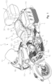
Fig. 1 is a left front perspective view of a vehicle of the present disclosure; -
Fig. 2 is a right rear perspective view of vehicle ofFig. 1 ; -
Fig. 3 is a left side view of the vehicle ofFig. 1 ; -
Fig. 4 is a right side view of the vehicle ofFig. 1 ; -
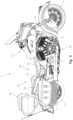
Fig. 5 is a top view of the vehicle ofFig. 1 ; -
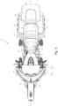
Fig. 6 is a front view of the vehicle ofFig. 1 ; -
Fig. 7 is a rear view of the vehicle ofFig. 1 ; -
Fig. 8 is a rear view of an operator area of the vehicle ofFig. 1 ; -
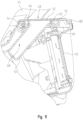
Fig. 9 is a left rear perspective view of a storage area of the operator area ofFig. 8 ; -
Fig. 10 is an exploded view of the storage area ofFig. 9 ; -
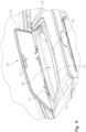
Fig. 11 is a cross-sectional view of the storage area ofFig. 8 , taken along line 11-11 ofFig. 8 ; -
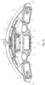
Fig. 12 is a top view of the operator area ofFig. 8 ; -
Fig. 13 is a side view of the vehicle ofFig. 1 with an operator positioned on the vehicle; -
Fig. 14 is a left front view of a front portion of the vehicle ofFig. 1 ; -
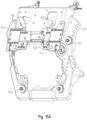
Fig. 15A is a left front view of a wiring harness and a support bracket positioned at the front portion ofFig. 14 ; -
Fig. 15B is an exploded view of the wiring harness and support bracket ofFig. 14 ; -
Fig. 16 is a left front perspective view of a triple clamp assembly configured to couple with the support bracket ofFigs. 15A and15B ; -
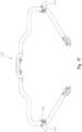
Fig. 17 is a rear perspective view of a highway bar of the vehicle ofFig. 1 ; -
Fig. 18 is an exploded view of a foot peg coupled to the highway bar ofFig. 17 ; -
Fig. 19 is a side view of a saddle bag of the vehicle ofFig. 1 ; -
Fig. 20 is a left front perspective view of a latch assembly of the saddle bag ofFig. 19 ; -
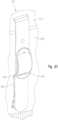
Fig. 21 is a left front perspective view of the latch assembly ofFig. 20 ; -
Fig. 22 is a left rear perspective view of a trunk assembly for the vehicle ofFig. 1 ; -
Fig. 23 is an exploded view of an underside of the trunk assembly ofFig. 22 ; and -
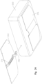
Fig. 24 is an exploded view of a support plate and a trunk of the trunk assembly ofFig. 22 . - The embodiments disclosed below are not intended to be exhaustive or to limit the invention to the precise forms disclosed in the following detailed description. Rather, the embodiments are chosen and described so that others skilled in the art may utilize their teachings. While the present invention primarily involves a motorcycle, it should be understood, that the invention may have application to other types of vehicles such as scooters and mopeds.
- With reference to
Figs. 1-7 , an illustrative embodiment of avehicle 2 is shown.Vehicle 2 is shown as a two-wheeled vehicle, such as a motorcycle, which includes a front ground-engaging member 4 with a front axis of rotation 5 (Fig. 3 ), a rear ground-engaging member 6 with a rear axis of rotation 7 (Fig. 13 ), aframe assembly 8 supported by ground-engaging members Fig. 5 ), and apowertrain assembly 10 supported byframe assembly 8. Powertrainassembly 10 includes anengine 12 and atransmission 14.Transmission 14 may be a shiftable transmission or a continuously-variable transmission.Engine 12 is operably coupled totransmission 14 and includes at least onecylinder 16 and, illustratively, includes twocylinders 16. Afuel tank 38 is fluidly coupled toengine 12 and positioned generally abovecylinders 16. - Referring to
Figs. 1-5 , aseat assembly 18 is coupled toframe assembly 8 and is positioned generally above at least a portion ofpowertrain assembly 10.Seat assembly 18 includes anoperator seat 20, defined by aseat bottom 22 and a seat back 24, and apassenger seat 26, defined by aseat bottom 28 and a seat back 30.Seat bottom 22 has acenter point 32 positioned longitudinally between afront extent 34 and a rear extent 36 (Fig. 3 ) thereof. As shown inFig. 3 ,front extent 34 ofseat bottom 22 is adjacent a rear extent offuel tank 38 - Referring to
Figs. 1-6 ,12 , and13 ,vehicle 2 includes anoperator area 40 positioned generally forward ofseat assembly 18 and rearward of at least a portion of a front fairing orbody panel 94 ofvehicle 2.Fairing 94 includes an upper extent defined by anupper lip 96. Acenter point 98 ofupper lip 96 aligns with longitudinal axis L and the uppermost extent ofupper lip 96 is defined at anupper extent 100 which is rearward and laterally outward ofcenter point 98.Fairing 94 extends rearwardly to arear extent 102 which is positioned generally above an upper extent offuel tank 38. -
Fairing 94 is coupled to atriple clamp assembly 104 of vehicle 2 (Fig. 16 ) and supports a headlight 106 (Fig. 6 ) forward oftriple clamp assembly 104.Triple clamp assembly 104 is operably coupled to a portion offrame assembly 8 through acenter coupler 108 and operably coupled to asteering assembly 42 through a bracket 110 (Fig. 16 ). Additional details of fairing 92 andtriple clamp assembly 104 may be disclosed inU.S. Patent Application Serial No. 14/077,037 (Attorney Docket No. PLR-12-26258.01P). - As shown in
Figs. 8-13 ,operator area 40 includes steeringassembly 42 with agripping surface 140 with a mid-point (Figs. 3 and13 ), awindshield 44, and adash assembly 46. Illustratively, steeringassembly 42 defines handlebars having grippingsurfaces 140 for the operator's hands. Alternatively, steeringassembly 42 may be a steering wheel or any other steering device configured to turnvehicle 2. Additionally, in one embodiment,windshield 44 is configured to move between a raised position which shields the operator from at least some air/wind whenvehicle 2 is moving and a lowered positioned in which may expose the operator to air/wind whenvehicle 2 is moving. - Referring now to
Figs. 8-13 ,dash assembly 46 ofoperator area 40 includes astorage area 48 in which an operator can put personal items during operation ofvehicle 2. In one embodiment,storage area 48 is positioned at an upper surface ofdash assembly 46 and is positioned adjacent a rear surface ofwindshield 44. Additionally, as shown inFig. 8 ,storage area 48 is positioned forward offuel tank 38. The position ofstorage area 48 provides the operator with easy access tostorage area 48 during operation ofvehicle 2. For example, the operator may reach forward to accessstorage area 48 without leaning forward on seat bottom 22 such thatvehicle 2 maintains the same course when the operator accessesstorage area 48. -
Illustrative storage area 48 includes astorage container 50 removably positioned within anopening 59 ofdash assembly 46. As shown inFigs. 9 and12 ,storage container 50 may include an electrical connector 60 (e.g., a USB port) for electrically connecting a device to an electrical system 220 (Fig. 14 ) ofvehicle 2. In one embodiment,storage container 50 is comprised of a polymeric material and, more particularly, a flexible polymeric material (e.g., rubber or silicone) such thatstorage container 50 can be compressed or otherwise manipulated to pullstorage container 50 from opening 59 and/or to put back withinopening 59.Storage container 50 includes anupstanding lip 62 and ashoulder 64 for coupling withdash assembly 46. More particularly, as shown inFig. 11 ,shoulder 64 receives atab 66 ofdash assembly 46 to couplestorage container 50 to dashassembly 46. Whenstorage container 50 is coupled to dashassembly 46, aninternal volume 68 ofstorage container 50 is angled such thatupstanding lip 62 is positioned rearward ofinternal volume 68. Additionally,lip 62 prevents water or other fluid from enteringinternal volume 68 ofstorage container 50. - Referring to
Figs. 8-12 ,storage area 48 also includes alid 52 pivotably coupled to a portion ofdash assembly 46 with hinges 54. Illustratively, hinges 54 are spring-loaded, however, hinges 54 may be any member configured to rotatelid 52 between a closed position (Fig. 8 ) and an open position (Fig. 9 ). When in the closed position ofFig. 8 ,lid 52 coversstorage container 50 to conceal the items withininternal volume 68 and is latched or otherwise coupled to dashassembly 46 with alatch member 56 extending fromlid 52 which is received within alatch aperture 58 ofdash assembly 46. In one embodiment, the operator may push down onlid 52 to releaselatch member 56 fromlatch aperture 58 andopen lid 52. Additionally, to closelid 52, the operator may pivotlid 52 downwardly to insertlatch member 56 intolatch aperture 58. - Referring to
Figs. 8 and11-13 ,dash assembly 46 also includes a plurality of visual indicators, including at least a first display or gauge 70, a second display or gauge 72, and a third display orgauge 74. In one embodiment, displays 70, 72, 74 may be movable or configured to tilt between upper and lower positions to accommodate the preferences of the operator. Illustratively, as shown inFigs. 8 and11 , at leastfirst display 70 is positioned rearward of and vertically belowlid 52 ofstorage area 48. Additionally, as shown inFig. 8 ,first display 70 is positioned intermediate second andthird displays Fig. 5 ) such that longitudinal axis L intersects acenter point 76 offirst display 70. First, second, andthird displays vehicle 2, ambient conditions, infotainment (e.g., GPS, radio, wireless connectivity, Bluetooth® connectivity, audio settings), and/or any other information that may be useful to the operator during operation ofvehicle 2. - In one embodiment, at least
first display 70 is a touch-screen display with a plurality of pixels configured to change in response to an operator input. For example, the operator may use his/her finger to select options onfirst display 70 and receive information aboutvehicle 2, ambient conditions, etc. Additionally,dash assembly 46 may support a plurality ofinputs 82 positioned adjacentfirst display 70 which also allow the operator to change the information presented onfirst display 70 and also access various features of vehicle 2 (e.g., a radio, GPS, Bluetooth®, a power or on/off input fordisplays inputs 82 are push buttons positioned along one side offirst display 70. -
Dash assembly 46 also may includeadditional inputs inputs 82 to control various functions ofvehicle 2. For example,input 86 may be the power button forvehicle 2 such thatinput 86 turnsvehicle 2 on and off. Additionally,input 84 may control the fog lights or other features ofvehicle 2. - In one embodiment,
first display 70 has a generally square cross-section defined by awidth 78 and aheight 80. Illustratively,width 78 may be approximately 5-7 inches (12.7-17.8 cm), for example 6.2 inches (15.7 cm), andheight 80 may be approximately 3-5 inches (7.2-12.7 cm), for example 3.8 inches (9.65). Second andthird displays second displays - As shown in
Figs. 8 ,11 ,12 , and13 ,dash assembly 46 also may include afirst visor 88 positioned directly abovefirst display 70, asecond visor 90 positioned directly abovesecond display 72, and athird visor 92 positioned directly abovethird display 74 to decrease any glare ondisplays visors displays displays displays Fig. 12 ,visors dash assembly 46. As such, the upper surface ofdash assembly 46 includes bothlid 62 ofstorage area 48 andvisors displays first visor 88 is positioned vertically intermediate anupper extent 142 and alower extent 144 of windshield 44 (Fig. 6 ). -
Fuel tank 38 also includes at least onedisplay 216 configured to display fuel information to the operator. As withdisplays display 216 onfuel tank 38 also may include avisor 218 which rearwardly overhangs the upper extent ofdisplay 216 to decrease glare on display 216 (Fig. 2 ,3 , and8 ). - Referring to
Fig. 13 , displays 70, 72, 74 are ergonomically positioned onvehicle 2 such that the operator does not need to lean forward when accessing displays 70, 72, 74. More particularly, displays 70, 72, 74 are positioned to be within the length of the arm of an average male operator (i.e., a male with measurements in the 50th percentile) such that the operator can accessdisplays Fig. 13 ,center point 76 offirst display 70 is positioned directly above one ofcylinders 16 and, illustratively, rearward of a front extent of one ofcylinders 16 ofengine 12. Additionally,center point 76 offirst display 70 is positioned abovefuel tank 38 and, more particularly, rearward of a front extent or plane offuel tank 38. Also,center point 76 offirst display 70 may be approximately 20-30 inches (50.8-76.2 cm) longitudinally forward offront extent 34 of seat bottom 22 and, more particularly, approximately 23.0-24.0 inches (58.4-60.9 cm) longitudinally forward offront extent 34.First display 70 also is positioned rearward ofrear extent 102 of fairing 94 andcenter point 76 offirst display 70 is positioned aboveuppermost extent 100 ofupper lip 96 of fairing 94. Further, in one embodiment, the lower extent offirst display 70 is positioned vertically abovetriple clamp assembly 104. Additionally, grippingsurface 140 of steeringassembly 42 is positioned vertically intermediate the upper and lower extents offirst display 70 such that the operator only needs to move his/her hand laterally inward to accessfirst display 70. More particularly,mid-point 141 of gripping surface 140 (Fig. 3 ) is positioned rearward offirst display 70 by approximately 8-11 inches (20.3-27.9 cm), for example approximately 9.3-9.7 inches (23.6-24.6 cm). By positioningfirst display 70 in these positional relationships relative to other components ofvehicle 2,first display 70 is ergonomically positioned for the operator when he/she is seated onseat 22 such that the operator does not need to lean forward to accessfirst display 70 when reaching forfirst display 70. -
First display 70 also is positioned rearward of front axis ofrotation 5 by at least 30% of a wheel base WB (Fig. 13 ) defined between axes ofrotation 5, 7 of ground-engagingmembers vehicle 2 may be approximately 65 inches (165.1 cm) and the longitudinal distance between front axis ofrotation 5 andcenter point 76 offirst display 70 may be approximately 32% of wheel base WB. Alternatively,first display 70 may be positioned rearward of front axis ofrotation 5 by as little as 5-29% of wheel base WB or as much as 31-85% of wheel base WB, or at any percentage between 5-85% of wheel base WB. - According to Table 1, in one example of vehicle 2, first display 70 is elevated to be nearer to the line of sight of the operator such that a horizontal plane D1 extending through center point 76 of first display 70 is positioned vertically above various components of vehicle 2 and first display 70 is positioned rearwardly to be within the length of the operator's arm such that a vertical plane D2 extending through center point 76 of first display 70 is positioned longitudinally rearward of various components of vehicle 2 to prevent the operator from leaning forward during operation of vehicle 2 to access first display 70 (
Fig. 13 ):Table 1 Distance (in/cm) of Plane D1 Vertically Above: Distance (in/cm) of Plane D2 Rearward of: Ground Surface G 44.4/111.76 (Distance 114 ( Fig. 13 ))N/A Front Axis of Rotation 5 32.0/81.28 (Distance 116 ( Fig. 13 ))21.0/53.3 (Distance 118 ( Fig. 13 )) 4Center Point 112 of Headlight 106 9.2/23.368 (Distance 120 ( Fig. 13 ))16.1/40.894 (Distance 122 ( Fig. 13 ))Center Coupler 108 of Triple Clamp Assembly 104 6.5/16.51 (Distance 124 ( Fig. 13 ))9.4/23.876 (Distance 126 ( Fig. 13 ))Upper Extent 100 of Fairing 94 -1.9/-4.826 (Distance 128 ( Fig. 13 ))N/A Center Point 98 of Upper Lip 96 of Fairing 94 -1.7/-4.318 (Distance 130 ( Fig. 13 ))9.7/24.638 (Distance 132 ( Fig. 13 ))Center Point 32 of Seat Bottom 22 16.0/40.64 (Distance 134 ( Fig. 13 ))-24.5/-62.23 (Distance 136 ( Fig. 13 ))Upper Extent of Fuel Tank 38 7.1/18.034 (Distance 138 ( Fig. 13 ))N/A - While one embodiment of vehicle 2 of
Fig. 13 includes first display 70 at the positions disclosed in Table 1, it should be understand that the position of first display 70 may be adjusted, such that center point 76 of first display 70 may be approximately 42-46 inches (106.7-116.8 cm) from ground surface G, approximately 30-35 inches (76.2-88.9 cm) above and approximately 19-24 inches (48.3-60.96 cm) rearward of front axis of rotation 5, approximately 8-11 inches (20.3-27.9 cm) above and approximately 15-18 inches (38.1-45.7 cm) rearward of center point 112 of headlight 106, approximately 5-7 inches (12.7-17.8 cm) above and approximately 7-11 inches (17.8-27.9 cm) rearward of center coupler 108 of triple clamp assembly 104, approximately 0.1-4 inches (.254-10.16 cm) below or approximately 0.1-2 inches (.254-5.08 cm) above upper extent 100 of fairing 94, approximately 0.1-3 inches (.254-7.62 cm) below or approximately 0.1-2.0 inches (.254-5.08 cm) above center point 98 of fairing 94, approximately 8-12 inches (20.3-30.5 cm) rearward of center point 98 of fairing 94, approximately 14-19 inches (35.6-48.3 cm) above and approximately 22-35 inches (55.9-88.9 cm) forward of center point 32 of seat bottom 22, and approximately 5-9 inches (12.7-21.6 cm) above the upper extent of fuel tank 38. Also, the vertical distance from the axis ofrotation 5 to axis D1 (116) is twice the vertical distance from the axis ofrotation 5 to the center of the seat (i.e. 116 minus 136). - Referring to
Figs. 15A-16 , awiring harness bracket 146 ofvehicle 2 is positioned forward offront display 70 and is configured to support electrical lines and wires ofelectrical system 220 ofvehicle 2. For example,wiring harness bracket 146 may be electrically coupled to display 70, 72, 74,inputs electrical connector 60,headlight 106, and other electrical components ofvehicle 2.Wiring harness bracket 146 is coupled to asupport member 148 withfasteners 154 which are received withinapertures 156 onsupport member 148.Support member 148 is coupled totriple clamp assembly 104 thoughfasteners 150 received withinapertures 152 ontriple clamp assembly 104. As shown inFigs. 15A and15B ,wiring harness bracket 146 includes a plurality of retainingmembers 158 which are configured to receive and organize electrical lines or wires such that at least a portion of the electrical wires onvehicle 2 are positioned onwiring harness bracket 146 to electrically couple with various electrical connectors and/or components ofvehicle 2. As such,vehicle 2 may be manufactured with similar electrical routing and tension in the electrical lines viawiring harness bracket 146 rather than eachvehicle 2 having a different routing configuration for the wiring. - As shown in
Figs. 17 and18 , in addition to positioningfirst display 70 at an ergonomic position for the rider,vehicle 2 also may include ahighway bar 160 with nubs or foot pegs 162 extending laterally outward fromhighway bar 160.Highway bar 160 is coupled to a portion offrame assembly 8 and is positioned forward of engine 12 (Fig. 1 ). Foot pegs 162 are removably coupled tohighway bar 160 with acoupler 164 having aninner member 164a and anouter member 164b coupled together withfasteners 166 which are received throughopenings 167 onouter member 164b andopenings 168 oninner member 164a. As such, foot pegs 162 may be added or removed fromhighway bar 160 and the position of foot pegs 162 onhighway bar 160 may be adjusted to accommodate the preferences of the operator. In one embodiment, foot pegs 162 may be integrally formed withouter member 164b. Illustratively, foot pegs 162 are rounded and define a tapered cone shape for supporting the operator's foot, however, foot pegs 162 may define any shape configured to support the operator's foot. By providing foot pegs 162 onhighway bar 160, the operator has an additional place to put his/her feet during operation ofvehicle 2. For example, foot pegs 162 are provided onvehicle 2 in addition to conventional foot pegs such that the operator has several options for where to position his/her feet during operation ofvehicle 2. More particularly, foot pegs 162 may allow the operator to move his/her feet from a straight forward position to relax his/her feet and legs during operation ofvehicle 2. - Referring to
Figs. 19-24 , a rear portion ofvehicle 2 includes at least onesaddle bag 170 and atrunk 172. Saddlebags 170 andtrunk 172 may be removable accessories forvehicle 2 or may be permanently fixed tovehicle 2. Illustratively, as shown inFigs. 1 and7 ,saddle bags 170 flank rear ground-engagingmember 6 and are positioned laterally outward frompassenger seat 26. Saddlebags 170 include astorage portion 174 and a lid or cover 176 which rotates relative tostorage portion 174 to expose or conceal any items positioned therein.Storage portion 174 and cover 176 may be comprised of any material, for example fabric, leather, or a hard plastic. - As shown in
Figs. 19-21 ,cover 176 is coupled tostorage portion 174 with at least one, and illustratively three, couplingmembers 178. Couplingmembers 178 may include anupper strap portion 180, a lower strap portion 182 (Fig. 21 ), a coupling member, illustratively abuckle 184, and a latch member, illustratively a combination lock 186 (Fig. 21 ). Illustratively,saddle bags 170 include twocombination locks 186, however, alternative embodiments ofsaddle bags 170 may include more or less than twocombination locks 186. - Referring to
Fig. 21 ,combination lock 186 has anupper member 188 coupled tolower strap portion 182 and alower member 190 coupled tostorage portion 174 with acoupling member 192, such as a strap, bracket, clasp, or any other device configured to couplecombination lock 186 tostorage portion 174.Upper member 188 is releasably coupled tolower member 190 withtabs 194 onlower member 190 which are received within anopening 196 ofupper member 188.Upper member 188 also may be locked withlower member 190 such thatdepressing tabs 194 does not releaseupper member 188 fromlower member 190. More particularly,upper member 188 includes locking dials 198 which includes numbers 0-9 and are configured to be set to a specific number to unlockupper member 188 fromlower member 190. For example, if the code forcombination lock 186 is 88, as shown inFig. 21 , then dials 198 must be rotated to 88 to releaseupper member 188 fromlower member 190. Whenever dials 198 are rotated to a number other than 88, thenupper member 188 will not release fromlower member 190. As such,saddle bags 170 may be locked to prevent someone from accessing any items withinstorage portion 174 when the operator is away fromvehicle 2. - In one embodiment, a vehicle control unit (not shown) may be configured to automatically lock any of the storage containers of
vehicle 2. For example, the vehicle control unit may automatically locksaddle bags 170 and/orlid 52 ofstorage container 50 ondash assembly 46 whenvehicle 2 is parked or whenwindshield 44 is in the lowered position becausewindshield 44 is likely to be in the lowered position whenvehicle 2 is not operating. In this embodiment,saddle bags 170 and/orstorage container 50 may remain open whenwindshield 44 is in the raised position, unless the operator specifically lockssaddle bags 170 and/orstorage container 50. Additionally,saddle bags 170 and/orstorage container 50 may be locked by a key, key fob, or any other mechanism. - Referring to
Figs. 22-24 ,vehicle 2 also may includetrunk 172 for additional storage. In one embodiment,trunk 172 may be removably coupled tovehicle 2 such that the operator can add or removetrunk 172 fromvehicle 2 whenever necessary.Trunk 172 includes astorage container 200, asupport plate 202 received within a sleeve orpocket 204 ofstorage container 200, and atrunk frame 208 which is coupled to supportplate 202 with alatch member 206.Support plate 202 is received withinsleeve 204 ofstorage container 200 and is configured to provide a flat lower surface ofstorage container 200 andcouple storage container 200 totrunk frame 208. A front end oftrunk frame 208 is coupled totrunk 172 with straps, a clip, a clamp, a latch, or any other type of coupling device. Illustratively, the front end oftrunk frame 208 is removably coupled totrunk 172 with straps 215 (Fig. 22 ). As shown inFig. 24 ,latch member 206 also may be coupled to supportplate 202 with a bracket orother coupling member 214. Couplingmember 214 may be secured to supportplate 202 with conventional fasteners, such as rivets, bolts, welds, etc.Support plate 202 is configured to be received withinsleeve 204 such thatbracket 214 is concealed butlatch member 206 extends through one end ofsleeve 204 to couple with a rear end oftrunk frame 208. Additionally,support plate 202 may includefasteners 216 which are received withinfasteners 218 onsleeve 204 to further securesupport plate 202 within sleeve 204 (Fig. 24 ). In one embodiment,fasteners 216 are female-type snaps andfasteners 218 are male-type snaps configured to receive a protrusion of the female-type snaps onsupport plate 202. Alternatively,fasteners coupling support plate 202 tosleeve 204, such as hook-and-loop fasteners or clips. -
Trunk frame 208 is coupled to frameassembly 8 or another component ofvehicle 2 at ends 210 oftrunk frame 208. For example, ends 210 may be received within an opening offrame assembly 8 ofvehicle 2. Additionally,latch member 206 is removably coupled to anouter extent 212 oftrunk frame 208 such thattrunk frame 208 is positioned belowstorage container 200, as shown inFig. 22 . As such, when the operator wants to removestorage container 200 fromvehicle 2, the operator actuateslatch member 206 to removestorage container 200 andsupport plate 202 fromvehicle 2. However,trunk frame 208 may remain coupled tovehicle 2 whenstorage container 200 is removed or, alternatively, the operator also may removetrunk frame 208 fromvehicle 2 whenstorage container 200 is removed. - In one embodiment,
trunk 172 is configured to include interchangeable components such that a different storage container may be coupled totrunk frame 208 by merely coupling the corresponding support plate of the different storage container totrunk frame 208. Alternatively, different storage containers may include sleeves which also can receivesupport plate 202 such that a different storage container can be mounted to supportplate 202 andtrunk frame 208.Vehicle 2 also may be configured to support embodiments of a trunk disclosed inU.S. Patent Application Serial No. 14/077,037 (Attorney Docket No. PLR-12-26258.01P).
Claims (9)
- A two-wheeled vehicle (2) having a longitudinal centerline, comprising a plurality of ground-engaging members (4, 6); an engine (12) with cylinders supported by the plurality of ground-engaging members (4, 6); a seat (20) supported by the plurality of ground-engaging members (4, 6) including a seat bottom (22), wherein the seat bottom (22) has a center point (32) positioned longitudinally between a front extent (34) and a rear extent (36) thereof; a fuel tank (38) positioned adjacent the seat (20); a steering assembly (42) operably coupled to at least one of the ground-engaging members, the steering assembly having a gripping surface (140); a front fairing (94) including an upper extent (100) defined by an upper lip (96) and a rear extent (102) positioned above an upper extend of the fuel tank (38), the front fairing (94) operably coupled to a triple clamp assembly (104) and the triple clamp assembly (104) operably coupled to a frame assembly (8) through a center coupler (108) and the triple clamp assembly (104) operably coupled to the steering assembly (42) by a bracket (110); a headlight (106) supported by the front fairing (94), the headlight (106) forward of the triple clamp assembly (104); an operator area (40) positioned forward of the seat assembly (18) and rearward of at least a portion of the front fairing (94); and a display (70) adjacent the steering assembly (42) and positioned vertically above the headlight (106), the display (70) being movable with the steering assembly (42) and intersecting the longitudinal centerline of the vehicle (2), and the display (70) being positioned rearward of a front plane of the fuel tank (38) and above the triple clamp assembly (104), characterized in that, the display (70) is positioned rearward of a rear extent (102) of the front fairing (94) and a front extent of the engine, and a center point (76) of the display (70) is positioned above uppermost extent (100) of the upper lip (96) of the front fairing (94), the uppermost extent is defined at the upper extent (100), which is rearward and laterally outward of a center point (98) of the upper lip (96) that aligns with the longitudinal centerline of the vehicle (2), wherein the fuel tank (38) is fluidly coupled to the engine (12) and positioned generally above the cylinders (16) of the engine (12).
- The vehicle of claim 1, wherein the display is positioned above an upper extent of the fuel tank.
- The vehicle of claim 1, wherein the display is vertically aligned with a front cylinder (16) of the engine.
- The vehicle of claim 1, wherein a lower extent of the display is positioned above an upper extent of the triple clamp assembly.
- The vehicle of any of claims 1-4, wherein the plurality of ground-engaging members includes a front ground-engaging member configured to rotate about a front axis of rotation (5) and a rear ground-engaging member configured to rotate about a rear axis of rotation (7), and a wheel base (WB) is defined between the front and rear axes of rotation, and the display is positioned rearward of the front axis of rotation by a distance (118) of at least 30% of the wheel base.
- The vehicle of any of claims 1-5, wherein the center point (76) of the display (70) is approximately 106.7-116.8 cm (42-46 inches) from a ground surface (G), approximately 76.2-88.9 cm (30-35 inches) above and approximately 48.3-60.96 cm (19-24 inches) rearward of a front axis of rotation (5), approximately 20.3-27.9 cm (8-11 inches) above and approximately 38.1-45.7 cm (15-18 inches) rearward of a center point (112) of the headlight (106), approximately 12.7-17.8 cm (5-7 inches) above and approximately 17.8-27.9 cm (7-11 inches) rearward of a center coupler (108) of the triple clamp assembly (104), approximately .254-10.16 cm (0.1-4 inches) below or approximately .254-5.08 cm (0.1-2 inches) above the upper extent (100) of the front fairing (94), approximately .254-7.62 cm (0.1-3 inches) below or approximately .254-5.08 cm (0.1-2.0 inches) above the center point (98) of the upper lip (96) of the front fairing (94), approximately 20.3-30.5 cm (8-12 inches) rearward of the center point (98) of the upper lip (96) of the front fairing (94), approximately 35.6-48.3 cm (14-19 inches) above and approximately 55.9-88.9 cm (22-35 inches) forward of the center point (32) of the seat bottom (22), and approximately 12.7-21.6 cm (5-9 inches) above the upper extent of the fuel tank (38) and wherein a vertical distance from between the front axis of rotation to a center of the seat is defined by a first vertical distance, and a second vertical distance (116) from a center point of the display to the front axis of rotation is 2 times the first distance.
- The vehicle of any of claims 1-6, further comprising a visor (88) coupled to an upper extent of the display and extending rearwardly from the display.
- The vehicle of claim 7, further comprising a windshield assembly, and the visor is positioned vertically intermediate an upper end and a lower end of the windshield assembly.
- The vehicle of any of claims 1-8 as dependent upon claim 4, the gripping surface (140) has a midpoint (141) positioned rearward from the display (70) by a distance in the range of 20.3-27.9 cm (8-11 inches) and the gripping surface is positioned vertically intermediate the upper and lower extents of the display (70).
Applications Claiming Priority (2)
| Application Number | Priority Date | Filing Date | Title |
|---|---|---|---|
| US14/985,673 US10315719B2 (en) | 2015-12-31 | 2015-12-31 | Two-wheeled vehicle |
| PCT/US2016/068849 WO2017117204A1 (en) | 2015-12-31 | 2016-12-28 | Two-wheeled vehicle |
Publications (2)
| Publication Number | Publication Date |
|---|---|
| EP3397549A1 EP3397549A1 (en) | 2018-11-07 |
| EP3397549B1 true EP3397549B1 (en) | 2024-07-24 |
Family
ID=57822097
Family Applications (1)
| Application Number | Title | Priority Date | Filing Date |
|---|---|---|---|
| EP16826866.2A Active EP3397549B1 (en) | 2015-12-31 | 2016-12-28 | Two-wheeled vehicle |
Country Status (7)
| Country | Link |
|---|---|
| US (1) | US10315719B2 (en) |
| EP (1) | EP3397549B1 (en) |
| JP (2) | JP2019500271A (en) |
| CN (2) | CN108463402A (en) |
| AU (1) | AU2016382788B2 (en) |
| CA (1) | CA3007113A1 (en) |
| WO (1) | WO2017117204A1 (en) |
Families Citing this family (8)
| Publication number | Priority date | Publication date | Assignee | Title |
|---|---|---|---|---|
| USD911879S1 (en) | 2018-09-10 | 2021-03-02 | Indian Motorcycle International, LLC | Motorcycle |
| USD958191S1 (en) * | 2018-11-27 | 2022-07-19 | Bayerische Motoren Werke Aktiengesellschaft | Engine and/or engine block |
| JP7331608B2 (en) | 2019-10-10 | 2023-08-23 | スズキ株式会社 | Straddle type vehicle external device support structure |
| US11718240B2 (en) | 2019-12-20 | 2023-08-08 | Polaris Industries Inc. | All-terrain vehicle |
| US11618521B2 (en) * | 2020-07-09 | 2023-04-04 | Zhejiang CFMOTO Power Co., Ltd. | Quick connect and disconnect latch mechanism for mounting accessories on offroad vehicles |
| USD1045399S1 (en) | 2021-03-30 | 2024-10-08 | Polaris Industries Inc. | Storage cover |
| US12077130B2 (en) | 2021-03-30 | 2024-09-03 | Polaris Industries Inc. | Accessories for off-road vehicles |
| US12194954B2 (en) | 2023-03-17 | 2025-01-14 | Polaris Industries Inc. | Integrated seat belt energy management loop |
Citations (2)
| Publication number | Priority date | Publication date | Assignee | Title |
|---|---|---|---|---|
| EP2738073A1 (en) * | 2012-03-02 | 2014-06-04 | Honda Motor Co., Ltd. | Saddle-type vehicle |
| US20150130209A1 (en) * | 2012-11-12 | 2015-05-14 | Indian Motorcycle International, LLC | Two-wheeled vehicle |
Family Cites Families (44)
| Publication number | Priority date | Publication date | Assignee | Title |
|---|---|---|---|---|
| JPH0239986U (en) * | 1988-09-09 | 1990-03-19 | ||
| US5513107A (en) | 1992-12-17 | 1996-04-30 | Ford Motor Company | Methods and apparatus for controlling operating subsystems of a motor vehicle |
| JP4430153B2 (en) | 1999-03-26 | 2010-03-10 | 本田技研工業株式会社 | Vehicle display device |
| US6343237B1 (en) | 1999-06-04 | 2002-01-29 | Clark Equipment Company | User interface functionality for power machine control system |
| EP1081035B1 (en) | 1999-09-06 | 2007-07-25 | Honda Giken Kogyo Kabushiki Kaisha | Motorcycle with navigation system carried thereon |
| JP2001278153A (en) * | 2000-04-03 | 2001-10-10 | Honda Motor Co Ltd | Motorcycle head-up display device |
| JP4168713B2 (en) * | 2002-09-13 | 2008-10-22 | スズキ株式会社 | Front structure of motorcycle |
| JP4318939B2 (en) * | 2003-03-14 | 2009-08-26 | 本田技研工業株式会社 | Motorcycle windshield device |
| JP4381768B2 (en) * | 2003-10-10 | 2009-12-09 | 本田技研工業株式会社 | Motorcycle storage equipment |
| JP4489404B2 (en) * | 2003-10-14 | 2010-06-23 | 本田技研工業株式会社 | Display device for motorcycle |
| US20050121935A1 (en) * | 2003-12-05 | 2005-06-09 | Bell Kevin R. | Stereophonic fairing accessory |
| US7317386B2 (en) | 2004-03-11 | 2008-01-08 | Bayerische Motoren Werke Aktiengesellschaft | Method and apparatus for the output of music information to an operator |
| JP4771403B2 (en) | 2004-09-29 | 2011-09-14 | 本田技研工業株式会社 | GPS built-in meter |
| JP4390203B2 (en) * | 2004-09-30 | 2009-12-24 | 本田技研工業株式会社 | Motorcycle navigation device |
| JP4459002B2 (en) * | 2004-09-30 | 2010-04-28 | 本田技研工業株式会社 | Motorcycle |
| JP4579081B2 (en) * | 2005-07-29 | 2010-11-10 | 本田技研工業株式会社 | Audio device arrangement structure for motorcycles |
| US7789416B2 (en) * | 2005-09-08 | 2010-09-07 | Honda Motor Co., Ltd. | Air bag module cover structure |
| JP4737529B2 (en) * | 2005-10-18 | 2011-08-03 | 本田技研工業株式会社 | Airbag support belt cover structure |
| JP4849458B2 (en) * | 2006-08-31 | 2012-01-11 | 本田技研工業株式会社 | Meter support structure |
| JP2008114654A (en) * | 2006-11-01 | 2008-05-22 | Yamaha Motor Co Ltd | Motorcycle |
| JP4550799B2 (en) | 2006-12-27 | 2010-09-22 | 本田技研工業株式会社 | Motorcycle |
| US7832516B2 (en) | 2007-01-17 | 2010-11-16 | Polaris Industries Inc. | Adjustable foot control for vehicle |
| CN101544193A (en) * | 2008-03-26 | 2009-09-30 | 光阳工业股份有限公司 | vehicle instrument |
| JP5086220B2 (en) * | 2008-09-30 | 2012-11-28 | 本田技研工業株式会社 | Vehicle storage box locking device |
| US20100097325A1 (en) | 2008-10-21 | 2010-04-22 | Daisuke Nagao | Touch screen assemblies and saddle-type vehicles having one or more touch screen assemblies |
| JP5460182B2 (en) * | 2009-08-27 | 2014-04-02 | 本田技研工業株式会社 | Motorcycle meter unit |
| JP3157689U (en) * | 2009-12-11 | 2010-02-25 | ヤマハ発動機株式会社 | Saddle riding vehicle |
| CN102686476B (en) * | 2009-12-25 | 2014-10-08 | 雅马哈发动机株式会社 | Driver characteristic judging device and saddled vehicle including said driver characteristic judging device |
| JP5560082B2 (en) * | 2010-03-31 | 2014-07-23 | 本田技研工業株式会社 | Information provision system for motorcycles |
| JP2012071644A (en) * | 2010-09-28 | 2012-04-12 | Yamaha Motor Co Ltd | Motorcycle |
| JP5955503B2 (en) * | 2010-12-27 | 2016-07-20 | 川崎重工業株式会社 | Vehicle handle support structure |
| SG189560A1 (en) * | 2011-10-11 | 2013-05-31 | 3M Innovative Properties Co | A display device |
| JP5912877B2 (en) * | 2012-05-31 | 2016-04-27 | 本田技研工業株式会社 | Auxiliary equipment mounting structure for saddle-ride type vehicles |
| JP5869964B2 (en) * | 2012-05-31 | 2016-02-24 | 本田技研工業株式会社 | Windproof structure for saddle-ride type vehicles |
| US9394859B2 (en) * | 2012-11-12 | 2016-07-19 | Indian Motorcycle International, LLC | Two-wheeled vehicle |
| EP2917094B1 (en) * | 2012-11-12 | 2020-09-30 | Indian Motorcycle International, LLC | Two-wheeled vehicle |
| US20140188537A1 (en) | 2013-01-02 | 2014-07-03 | Primordial | System and method for crowdsourcing map production |
| US9731782B2 (en) * | 2013-02-08 | 2017-08-15 | Paleo-Tech Concepts | Sport motorcycle GPS bracket |
| US9117182B2 (en) | 2013-02-14 | 2015-08-25 | Anshuman Bapna | Method and system for dynamic travel plan management |
| JP5864483B2 (en) * | 2013-07-10 | 2016-02-17 | 本田技研工業株式会社 | Front structure of saddle-ride type vehicle |
| WO2015083206A1 (en) * | 2013-12-06 | 2015-06-11 | 川崎重工業株式会社 | Two-wheeled motor vehicle |
| JP6050292B2 (en) * | 2014-08-20 | 2016-12-21 | 本田技研工業株式会社 | Wind screen control device |
| JP6368237B2 (en) * | 2014-12-19 | 2018-08-01 | 川崎重工業株式会社 | Saddle riding vehicle |
| JP6282991B2 (en) * | 2015-03-13 | 2018-02-21 | 本田技研工業株式会社 | Body cover structure for saddle-ride type vehicles |
-
2015
- 2015-12-31 US US14/985,673 patent/US10315719B2/en active Active
-
2016
- 2016-12-28 CN CN201680077357.7A patent/CN108463402A/en active Pending
- 2016-12-28 AU AU2016382788A patent/AU2016382788B2/en not_active Expired - Fee Related
- 2016-12-28 EP EP16826866.2A patent/EP3397549B1/en active Active
- 2016-12-28 WO PCT/US2016/068849 patent/WO2017117204A1/en not_active Ceased
- 2016-12-28 JP JP2018534123A patent/JP2019500271A/en active Pending
- 2016-12-28 CN CN202011485176.2A patent/CN112550537A/en active Pending
- 2016-12-28 CA CA3007113A patent/CA3007113A1/en not_active Abandoned
-
2020
- 2020-04-27 JP JP2020078076A patent/JP7053715B2/en active Active
Patent Citations (2)
| Publication number | Priority date | Publication date | Assignee | Title |
|---|---|---|---|---|
| EP2738073A1 (en) * | 2012-03-02 | 2014-06-04 | Honda Motor Co., Ltd. | Saddle-type vehicle |
| US20150130209A1 (en) * | 2012-11-12 | 2015-05-14 | Indian Motorcycle International, LLC | Two-wheeled vehicle |
Also Published As
| Publication number | Publication date |
|---|---|
| EP3397549A1 (en) | 2018-11-07 |
| JP2020128207A (en) | 2020-08-27 |
| JP7053715B2 (en) | 2022-04-12 |
| US10315719B2 (en) | 2019-06-11 |
| AU2016382788B2 (en) | 2019-11-21 |
| CA3007113A1 (en) | 2017-07-06 |
| US20170190373A1 (en) | 2017-07-06 |
| CN112550537A (en) | 2021-03-26 |
| CN108463402A (en) | 2018-08-28 |
| AU2016382788A1 (en) | 2018-08-02 |
| JP2019500271A (en) | 2019-01-10 |
| WO2017117204A1 (en) | 2017-07-06 |
Similar Documents
| Publication | Publication Date | Title |
|---|---|---|
| AU2016382788B2 (en) | Two-wheeled vehicle | |
| CA3046653C (en) | Air intake assembly for a utility vehicle | |
| US9776481B2 (en) | Side-by-side vehicle | |
| US7543836B2 (en) | Flip-down footrest for an all-terrain vehicle | |
| US8182018B2 (en) | Dash assembly for golf cars or similar vehicles | |
| US7490890B2 (en) | Vehicle | |
| EP1520748B1 (en) | Vehicular seat structure | |
| US20150130209A1 (en) | Two-wheeled vehicle | |
| WO2003057525A1 (en) | Rear seats for a vehicle | |
| AU2018222903A1 (en) | Two-wheeled vehicle | |
| BR102016001144B1 (en) | STRUCTURE OF VEHICLE STORAGE PART OF THE TYPE TO ASSEMBLE | |
| CN101468670B (en) | Car seat structure | |
| CN103448846A (en) | Auxiliary machine mounting structure of saddle-ride type vehicle | |
| EP3150474B1 (en) | Battery compartment for saddle-type vehicle | |
| JP6022875B2 (en) | Mounting structure of portable information terminal for saddle-ride type vehicle | |
| EP0891920B1 (en) | Two-wheeled vehicle with adjustable shell, accessible through side-doors | |
| CN101423083A (en) | Article storing structure for vehicle | |
| US6247549B1 (en) | Motorcycle having a swivellable seat | |
| JP2013193646A (en) | Housing part structure for saddle riding type vehicle | |
| TWI288722B (en) | Bodywork of a motorcycle | |
| US10793213B2 (en) | Saddle type vehicle | |
| BR102015023990B1 (en) | FUEL TANK FIXING STRUCTURE OF A MOUNTED DRIVE TYPE VEHICLE | |
| JP2015131556A (en) | The structure around the rear seat of a saddle-ride type vehicle | |
| JP2016094131A (en) | Multipurpose vehicle | |
| CN204236640U (en) | There is the seat cushion of various states |
Legal Events
| Date | Code | Title | Description |
|---|---|---|---|
| STAA | Information on the status of an ep patent application or granted ep patent |
Free format text: STATUS: UNKNOWN |
|
| STAA | Information on the status of an ep patent application or granted ep patent |
Free format text: STATUS: THE INTERNATIONAL PUBLICATION HAS BEEN MADE |
|
| PUAI | Public reference made under article 153(3) epc to a published international application that has entered the european phase |
Free format text: ORIGINAL CODE: 0009012 |
|
| STAA | Information on the status of an ep patent application or granted ep patent |
Free format text: STATUS: REQUEST FOR EXAMINATION WAS MADE |
|
| 17P | Request for examination filed |
Effective date: 20180613 |
|
| AK | Designated contracting states |
Kind code of ref document: A1 Designated state(s): AL AT BE BG CH CY CZ DE DK EE ES FI FR GB GR HR HU IE IS IT LI LT LU LV MC MK MT NL NO PL PT RO RS SE SI SK SM TR |
|
| AX | Request for extension of the european patent |
Extension state: BA ME |
|
| RIN1 | Information on inventor provided before grant (corrected) |
Inventor name: DAVIS, CLARK, D. Inventor name: KRUGER, STEVEN, F. Inventor name: GSCHWIND, MATTHEW, R. Inventor name: QUADE, NEIL, P. Inventor name: FELDMAN, JOHN, E. Inventor name: EDEL, JOSH, L. |
|
| DAV | Request for validation of the european patent (deleted) | ||
| DAX | Request for extension of the european patent (deleted) | ||
| STAA | Information on the status of an ep patent application or granted ep patent |
Free format text: STATUS: EXAMINATION IS IN PROGRESS |
|
| 17Q | First examination report despatched |
Effective date: 20190621 |
|
| P01 | Opt-out of the competence of the unified patent court (upc) registered |
Effective date: 20230513 |
|
| GRAP | Despatch of communication of intention to grant a patent |
Free format text: ORIGINAL CODE: EPIDOSNIGR1 |
|
| STAA | Information on the status of an ep patent application or granted ep patent |
Free format text: STATUS: GRANT OF PATENT IS INTENDED |
|
| INTG | Intention to grant announced |
Effective date: 20240226 |
|
| GRAS | Grant fee paid |
Free format text: ORIGINAL CODE: EPIDOSNIGR3 |
|
| GRAA | (expected) grant |
Free format text: ORIGINAL CODE: 0009210 |
|
| STAA | Information on the status of an ep patent application or granted ep patent |
Free format text: STATUS: THE PATENT HAS BEEN GRANTED |
|
| AK | Designated contracting states |
Kind code of ref document: B1 Designated state(s): AL AT BE BG CH CY CZ DE DK EE ES FI FR GB GR HR HU IE IS IT LI LT LU LV MC MK MT NL NO PL PT RO RS SE SI SK SM TR |
|
| REG | Reference to a national code |
Ref country code: GB Ref legal event code: FG4D |
|
| REG | Reference to a national code |
Ref country code: CH Ref legal event code: EP |
|
| REG | Reference to a national code |
Ref country code: DE Ref legal event code: R096 Ref document number: 602016088571 Country of ref document: DE |
|
| REG | Reference to a national code |
Ref country code: IE Ref legal event code: FG4D |
|
| REG | Reference to a national code |
Ref country code: LT Ref legal event code: MG9D |
|
| REG | Reference to a national code |
Ref country code: NL Ref legal event code: MP Effective date: 20240724 |
|
| PG25 | Lapsed in a contracting state [announced via postgrant information from national office to epo] |
Ref country code: PT Free format text: LAPSE BECAUSE OF FAILURE TO SUBMIT A TRANSLATION OF THE DESCRIPTION OR TO PAY THE FEE WITHIN THE PRESCRIBED TIME-LIMIT Effective date: 20241125 |
|
| REG | Reference to a national code |
Ref country code: AT Ref legal event code: MK05 Ref document number: 1706073 Country of ref document: AT Kind code of ref document: T Effective date: 20240724 |
|
| PG25 | Lapsed in a contracting state [announced via postgrant information from national office to epo] |
Ref country code: NL Free format text: LAPSE BECAUSE OF FAILURE TO SUBMIT A TRANSLATION OF THE DESCRIPTION OR TO PAY THE FEE WITHIN THE PRESCRIBED TIME-LIMIT Effective date: 20240724 |
|
| PG25 | Lapsed in a contracting state [announced via postgrant information from national office to epo] |
Ref country code: PT Free format text: LAPSE BECAUSE OF FAILURE TO SUBMIT A TRANSLATION OF THE DESCRIPTION OR TO PAY THE FEE WITHIN THE PRESCRIBED TIME-LIMIT Effective date: 20241125 Ref country code: NL Free format text: LAPSE BECAUSE OF FAILURE TO SUBMIT A TRANSLATION OF THE DESCRIPTION OR TO PAY THE FEE WITHIN THE PRESCRIBED TIME-LIMIT Effective date: 20240724 |
|
| PG25 | Lapsed in a contracting state [announced via postgrant information from national office to epo] |
Ref country code: NO Free format text: LAPSE BECAUSE OF FAILURE TO SUBMIT A TRANSLATION OF THE DESCRIPTION OR TO PAY THE FEE WITHIN THE PRESCRIBED TIME-LIMIT Effective date: 20241024 |
|
| PG25 | Lapsed in a contracting state [announced via postgrant information from national office to epo] |
Ref country code: FI Free format text: LAPSE BECAUSE OF FAILURE TO SUBMIT A TRANSLATION OF THE DESCRIPTION OR TO PAY THE FEE WITHIN THE PRESCRIBED TIME-LIMIT Effective date: 20240724 Ref country code: GR Free format text: LAPSE BECAUSE OF FAILURE TO SUBMIT A TRANSLATION OF THE DESCRIPTION OR TO PAY THE FEE WITHIN THE PRESCRIBED TIME-LIMIT Effective date: 20241025 Ref country code: PL Free format text: LAPSE BECAUSE OF FAILURE TO SUBMIT A TRANSLATION OF THE DESCRIPTION OR TO PAY THE FEE WITHIN THE PRESCRIBED TIME-LIMIT Effective date: 20240724 |
|
| PG25 | Lapsed in a contracting state [announced via postgrant information from national office to epo] |
Ref country code: BG Free format text: LAPSE BECAUSE OF FAILURE TO SUBMIT A TRANSLATION OF THE DESCRIPTION OR TO PAY THE FEE WITHIN THE PRESCRIBED TIME-LIMIT Effective date: 20240724 |
|
| PG25 | Lapsed in a contracting state [announced via postgrant information from national office to epo] |
Ref country code: LV Free format text: LAPSE BECAUSE OF FAILURE TO SUBMIT A TRANSLATION OF THE DESCRIPTION OR TO PAY THE FEE WITHIN THE PRESCRIBED TIME-LIMIT Effective date: 20240724 |
|
| PG25 | Lapsed in a contracting state [announced via postgrant information from national office to epo] |
Ref country code: AT Free format text: LAPSE BECAUSE OF FAILURE TO SUBMIT A TRANSLATION OF THE DESCRIPTION OR TO PAY THE FEE WITHIN THE PRESCRIBED TIME-LIMIT Effective date: 20240724 Ref country code: IS Free format text: LAPSE BECAUSE OF FAILURE TO SUBMIT A TRANSLATION OF THE DESCRIPTION OR TO PAY THE FEE WITHIN THE PRESCRIBED TIME-LIMIT Effective date: 20241124 |
|
| PG25 | Lapsed in a contracting state [announced via postgrant information from national office to epo] |
Ref country code: HR Free format text: LAPSE BECAUSE OF FAILURE TO SUBMIT A TRANSLATION OF THE DESCRIPTION OR TO PAY THE FEE WITHIN THE PRESCRIBED TIME-LIMIT Effective date: 20240724 |
|
| PG25 | Lapsed in a contracting state [announced via postgrant information from national office to epo] |
Ref country code: ES Free format text: LAPSE BECAUSE OF FAILURE TO SUBMIT A TRANSLATION OF THE DESCRIPTION OR TO PAY THE FEE WITHIN THE PRESCRIBED TIME-LIMIT Effective date: 20240724 Ref country code: RS Free format text: LAPSE BECAUSE OF FAILURE TO SUBMIT A TRANSLATION OF THE DESCRIPTION OR TO PAY THE FEE WITHIN THE PRESCRIBED TIME-LIMIT Effective date: 20241024 |
|
| PG25 | Lapsed in a contracting state [announced via postgrant information from national office to epo] |
Ref country code: RS Free format text: LAPSE BECAUSE OF FAILURE TO SUBMIT A TRANSLATION OF THE DESCRIPTION OR TO PAY THE FEE WITHIN THE PRESCRIBED TIME-LIMIT Effective date: 20241024 Ref country code: PL Free format text: LAPSE BECAUSE OF FAILURE TO SUBMIT A TRANSLATION OF THE DESCRIPTION OR TO PAY THE FEE WITHIN THE PRESCRIBED TIME-LIMIT Effective date: 20240724 Ref country code: NO Free format text: LAPSE BECAUSE OF FAILURE TO SUBMIT A TRANSLATION OF THE DESCRIPTION OR TO PAY THE FEE WITHIN THE PRESCRIBED TIME-LIMIT Effective date: 20241024 Ref country code: LV Free format text: LAPSE BECAUSE OF FAILURE TO SUBMIT A TRANSLATION OF THE DESCRIPTION OR TO PAY THE FEE WITHIN THE PRESCRIBED TIME-LIMIT Effective date: 20240724 Ref country code: IS Free format text: LAPSE BECAUSE OF FAILURE TO SUBMIT A TRANSLATION OF THE DESCRIPTION OR TO PAY THE FEE WITHIN THE PRESCRIBED TIME-LIMIT Effective date: 20241124 Ref country code: HR Free format text: LAPSE BECAUSE OF FAILURE TO SUBMIT A TRANSLATION OF THE DESCRIPTION OR TO PAY THE FEE WITHIN THE PRESCRIBED TIME-LIMIT Effective date: 20240724 Ref country code: GR Free format text: LAPSE BECAUSE OF FAILURE TO SUBMIT A TRANSLATION OF THE DESCRIPTION OR TO PAY THE FEE WITHIN THE PRESCRIBED TIME-LIMIT Effective date: 20241025 Ref country code: FI Free format text: LAPSE BECAUSE OF FAILURE TO SUBMIT A TRANSLATION OF THE DESCRIPTION OR TO PAY THE FEE WITHIN THE PRESCRIBED TIME-LIMIT Effective date: 20240724 Ref country code: ES Free format text: LAPSE BECAUSE OF FAILURE TO SUBMIT A TRANSLATION OF THE DESCRIPTION OR TO PAY THE FEE WITHIN THE PRESCRIBED TIME-LIMIT Effective date: 20240724 Ref country code: BG Free format text: LAPSE BECAUSE OF FAILURE TO SUBMIT A TRANSLATION OF THE DESCRIPTION OR TO PAY THE FEE WITHIN THE PRESCRIBED TIME-LIMIT Effective date: 20240724 Ref country code: AT Free format text: LAPSE BECAUSE OF FAILURE TO SUBMIT A TRANSLATION OF THE DESCRIPTION OR TO PAY THE FEE WITHIN THE PRESCRIBED TIME-LIMIT Effective date: 20240724 |
|
| PG25 | Lapsed in a contracting state [announced via postgrant information from national office to epo] |
Ref country code: SM Free format text: LAPSE BECAUSE OF FAILURE TO SUBMIT A TRANSLATION OF THE DESCRIPTION OR TO PAY THE FEE WITHIN THE PRESCRIBED TIME-LIMIT Effective date: 20240724 Ref country code: DK Free format text: LAPSE BECAUSE OF FAILURE TO SUBMIT A TRANSLATION OF THE DESCRIPTION OR TO PAY THE FEE WITHIN THE PRESCRIBED TIME-LIMIT Effective date: 20240724 Ref country code: RO Free format text: LAPSE BECAUSE OF FAILURE TO SUBMIT A TRANSLATION OF THE DESCRIPTION OR TO PAY THE FEE WITHIN THE PRESCRIBED TIME-LIMIT Effective date: 20240724 |
|
| PG25 | Lapsed in a contracting state [announced via postgrant information from national office to epo] |
Ref country code: EE Free format text: LAPSE BECAUSE OF FAILURE TO SUBMIT A TRANSLATION OF THE DESCRIPTION OR TO PAY THE FEE WITHIN THE PRESCRIBED TIME-LIMIT Effective date: 20240724 |
|
| PG25 | Lapsed in a contracting state [announced via postgrant information from national office to epo] |
Ref country code: CZ Free format text: LAPSE BECAUSE OF FAILURE TO SUBMIT A TRANSLATION OF THE DESCRIPTION OR TO PAY THE FEE WITHIN THE PRESCRIBED TIME-LIMIT Effective date: 20240724 |
|
| REG | Reference to a national code |
Ref country code: DE Ref legal event code: R097 Ref document number: 602016088571 Country of ref document: DE |
|
| PG25 | Lapsed in a contracting state [announced via postgrant information from national office to epo] |
Ref country code: IT Free format text: LAPSE BECAUSE OF FAILURE TO SUBMIT A TRANSLATION OF THE DESCRIPTION OR TO PAY THE FEE WITHIN THE PRESCRIBED TIME-LIMIT Effective date: 20240724 Ref country code: SK Free format text: LAPSE BECAUSE OF FAILURE TO SUBMIT A TRANSLATION OF THE DESCRIPTION OR TO PAY THE FEE WITHIN THE PRESCRIBED TIME-LIMIT Effective date: 20240724 |
|
| PLBE | No opposition filed within time limit |
Free format text: ORIGINAL CODE: 0009261 |
|
| STAA | Information on the status of an ep patent application or granted ep patent |
Free format text: STATUS: NO OPPOSITION FILED WITHIN TIME LIMIT |
|
| 26N | No opposition filed |
Effective date: 20250425 |
|
| PG25 | Lapsed in a contracting state [announced via postgrant information from national office to epo] |
Ref country code: MC Free format text: LAPSE BECAUSE OF FAILURE TO SUBMIT A TRANSLATION OF THE DESCRIPTION OR TO PAY THE FEE WITHIN THE PRESCRIBED TIME-LIMIT Effective date: 20240724 |
|
| REG | Reference to a national code |
Ref country code: CH Ref legal event code: PL |
|
| PG25 | Lapsed in a contracting state [announced via postgrant information from national office to epo] |
Ref country code: LU Free format text: LAPSE BECAUSE OF NON-PAYMENT OF DUE FEES Effective date: 20241228 |
|
| GBPC | Gb: european patent ceased through non-payment of renewal fee |
Effective date: 20241228 |
|
| PG25 | Lapsed in a contracting state [announced via postgrant information from national office to epo] |
Ref country code: SE Free format text: LAPSE BECAUSE OF FAILURE TO SUBMIT A TRANSLATION OF THE DESCRIPTION OR TO PAY THE FEE WITHIN THE PRESCRIBED TIME-LIMIT Effective date: 20240724 |
|
| REG | Reference to a national code |
Ref country code: BE Ref legal event code: MM Effective date: 20241231 |
|
| PG25 | Lapsed in a contracting state [announced via postgrant information from national office to epo] |
Ref country code: BE Free format text: LAPSE BECAUSE OF NON-PAYMENT OF DUE FEES Effective date: 20241231 Ref country code: GB Free format text: LAPSE BECAUSE OF NON-PAYMENT OF DUE FEES Effective date: 20241228 |
|
| PG25 | Lapsed in a contracting state [announced via postgrant information from national office to epo] |
Ref country code: CH Free format text: LAPSE BECAUSE OF NON-PAYMENT OF DUE FEES Effective date: 20241231 |
|
| PG25 | Lapsed in a contracting state [announced via postgrant information from national office to epo] |
Ref country code: IE Free format text: LAPSE BECAUSE OF NON-PAYMENT OF DUE FEES Effective date: 20241228 |
|
| PGFP | Annual fee paid to national office [announced via postgrant information from national office to epo] |
Ref country code: DE Payment date: 20251126 Year of fee payment: 10 |
|
| PGFP | Annual fee paid to national office [announced via postgrant information from national office to epo] |
Ref country code: FR Payment date: 20251120 Year of fee payment: 10 |
|
| PG25 | Lapsed in a contracting state [announced via postgrant information from national office to epo] |
Ref country code: CY Free format text: LAPSE BECAUSE OF FAILURE TO SUBMIT A TRANSLATION OF THE DESCRIPTION OR TO PAY THE FEE WITHIN THE PRESCRIBED TIME-LIMIT Effective date: 20240724 |