EP3397507B1 - Non-pneumatic wheel - Google Patents
Non-pneumatic wheel Download PDFInfo
- Publication number
- EP3397507B1 EP3397507B1 EP17700756.4A EP17700756A EP3397507B1 EP 3397507 B1 EP3397507 B1 EP 3397507B1 EP 17700756 A EP17700756 A EP 17700756A EP 3397507 B1 EP3397507 B1 EP 3397507B1
- Authority
- EP
- European Patent Office
- Prior art keywords
- spoke
- shear
- spoke portion
- pneumatic wheel
- hub
- Prior art date
- Legal status (The legal status is an assumption and is not a legal conclusion. Google has not performed a legal analysis and makes no representation as to the accuracy of the status listed.)
- Active
Links
Images




Classifications
-
- B—PERFORMING OPERATIONS; TRANSPORTING
- B60—VEHICLES IN GENERAL
- B60B—VEHICLE WHEELS; CASTORS; AXLES FOR WHEELS OR CASTORS; INCREASING WHEEL ADHESION
- B60B9/00—Wheels of high resiliency, e.g. with conical interacting pressure-surfaces
- B60B9/26—Wheels of high resiliency, e.g. with conical interacting pressure-surfaces comprising resilient spokes
-
- B—PERFORMING OPERATIONS; TRANSPORTING
- B60—VEHICLES IN GENERAL
- B60B—VEHICLE WHEELS; CASTORS; AXLES FOR WHEELS OR CASTORS; INCREASING WHEEL ADHESION
- B60B5/00—Wheels, spokes, disc bodies, rims, hubs, wholly or predominantly made of non-metallic material
- B60B5/02—Wheels, spokes, disc bodies, rims, hubs, wholly or predominantly made of non-metallic material made of synthetic material
-
- B—PERFORMING OPERATIONS; TRANSPORTING
- B60—VEHICLES IN GENERAL
- B60C—VEHICLE TYRES; TYRE INFLATION; TYRE CHANGING; CONNECTING VALVES TO INFLATABLE ELASTIC BODIES IN GENERAL; DEVICES OR ARRANGEMENTS RELATED TO TYRES
- B60C7/00—Non-inflatable or solid tyres
- B60C7/10—Non-inflatable or solid tyres characterised by means for increasing resiliency
- B60C7/102—Tyres built-up with separate rubber parts
-
- B—PERFORMING OPERATIONS; TRANSPORTING
- B60—VEHICLES IN GENERAL
- B60C—VEHICLE TYRES; TYRE INFLATION; TYRE CHANGING; CONNECTING VALVES TO INFLATABLE ELASTIC BODIES IN GENERAL; DEVICES OR ARRANGEMENTS RELATED TO TYRES
- B60C7/00—Non-inflatable or solid tyres
- B60C7/10—Non-inflatable or solid tyres characterised by means for increasing resiliency
- B60C7/14—Non-inflatable or solid tyres characterised by means for increasing resiliency using springs
- B60C7/16—Non-inflatable or solid tyres characterised by means for increasing resiliency using springs of helical or flat coil form
-
- B—PERFORMING OPERATIONS; TRANSPORTING
- B60—VEHICLES IN GENERAL
- B60B—VEHICLE WHEELS; CASTORS; AXLES FOR WHEELS OR CASTORS; INCREASING WHEEL ADHESION
- B60B1/00—Spoked wheels; Spokes thereof
- B60B1/02—Wheels with wire or other tension spokes
-
- B—PERFORMING OPERATIONS; TRANSPORTING
- B60—VEHICLES IN GENERAL
- B60B—VEHICLE WHEELS; CASTORS; AXLES FOR WHEELS OR CASTORS; INCREASING WHEEL ADHESION
- B60B2360/00—Materials; Physical forms thereof
- B60B2360/30—Synthetic materials
-
- B—PERFORMING OPERATIONS; TRANSPORTING
- B60—VEHICLES IN GENERAL
- B60B—VEHICLE WHEELS; CASTORS; AXLES FOR WHEELS OR CASTORS; INCREASING WHEEL ADHESION
- B60B2360/00—Materials; Physical forms thereof
- B60B2360/30—Synthetic materials
- B60B2360/34—Reinforced plastics
-
- B—PERFORMING OPERATIONS; TRANSPORTING
- B60—VEHICLES IN GENERAL
- B60B—VEHICLE WHEELS; CASTORS; AXLES FOR WHEELS OR CASTORS; INCREASING WHEEL ADHESION
- B60B2360/00—Materials; Physical forms thereof
- B60B2360/30—Synthetic materials
- B60B2360/36—Composite materials
-
- B—PERFORMING OPERATIONS; TRANSPORTING
- B60—VEHICLES IN GENERAL
- B60B—VEHICLE WHEELS; CASTORS; AXLES FOR WHEELS OR CASTORS; INCREASING WHEEL ADHESION
- B60B2360/00—Materials; Physical forms thereof
- B60B2360/50—Rubbers
-
- B—PERFORMING OPERATIONS; TRANSPORTING
- B60—VEHICLES IN GENERAL
- B60B—VEHICLE WHEELS; CASTORS; AXLES FOR WHEELS OR CASTORS; INCREASING WHEEL ADHESION
- B60B2900/00—Purpose of invention
- B60B2900/20—Avoidance of
- B60B2900/212—Damage
-
- B—PERFORMING OPERATIONS; TRANSPORTING
- B60—VEHICLES IN GENERAL
- B60B—VEHICLE WHEELS; CASTORS; AXLES FOR WHEELS OR CASTORS; INCREASING WHEEL ADHESION
- B60B2900/00—Purpose of invention
- B60B2900/30—Increase in
- B60B2900/313—Resiliency
-
- B—PERFORMING OPERATIONS; TRANSPORTING
- B60—VEHICLES IN GENERAL
- B60B—VEHICLE WHEELS; CASTORS; AXLES FOR WHEELS OR CASTORS; INCREASING WHEEL ADHESION
- B60B2900/00—Purpose of invention
- B60B2900/30—Increase in
- B60B2900/321—Lifetime
-
- B—PERFORMING OPERATIONS; TRANSPORTING
- B60—VEHICLES IN GENERAL
- B60B—VEHICLE WHEELS; CASTORS; AXLES FOR WHEELS OR CASTORS; INCREASING WHEEL ADHESION
- B60B2900/00—Purpose of invention
- B60B2900/70—Adaptation for
- B60B2900/711—High loads, e.g. by reinforcements
-
- B—PERFORMING OPERATIONS; TRANSPORTING
- B60—VEHICLES IN GENERAL
- B60C—VEHICLE TYRES; TYRE INFLATION; TYRE CHANGING; CONNECTING VALVES TO INFLATABLE ELASTIC BODIES IN GENERAL; DEVICES OR ARRANGEMENTS RELATED TO TYRES
- B60C7/00—Non-inflatable or solid tyres
- B60C7/10—Non-inflatable or solid tyres characterised by means for increasing resiliency
- B60C7/14—Non-inflatable or solid tyres characterised by means for increasing resiliency using springs
- B60C7/146—Non-inflatable or solid tyres characterised by means for increasing resiliency using springs extending substantially radially, e.g. like spokes
Definitions
- the subject matter relates to a compliant non-pneumatic wheel possessing spokes which apply tension to the outer band by shear deformation.
- non-pneumatic wheels are described e.g., in U.S. Pat. Nos. 6,769,465 ; 6,994,134 ; 7,013,939 ; and 7,201,194 .
- Some non-pneumatic tire constructions incorporate a shear band, embodiments of which are described in e.g., U.S. Pat. Nos. 6,769,465 and 7,201,194 .
- Such non-pneumatic tires provide advantages in tire performance without relying upon a gas inflation pressure for support of the loads applied to the tire.
- Other examples of non-pneumatic wheels are disclosed in US2013233458A1 , FR883963A and WO2008041927A1 .
- Tension of the spokes is countered by circumferential compression in the outer band of the wheel.
- Uniform spoke tension be created by a uniform pull of each of the spokes.
- the spokes at the top of the wheel carry a larger amount of tension which is proportional to the load applied to the wheel.
- This load carrying mechanism is similar to how the radial cords of a pneumatic tire carry the load of the vehicle on the top of the rim and is generally referred to as a "top loading wheels.”
- the outer band When a tire encounters an obstacle, such as may be encountered by a tire rolling over a surface that is not smooth or when encountering an obstacle, such as a rock, crack, pothole, or curb, the outer band is momentarily displaced and momentarily deforming the spokes. If the spokes have a high stiffness rate, the deformation caused by the obstacle creates a larger load transmitted to the vehicle than if the spokes have a low stiffness rate. The momentary high load created by the obstacle is perceived by the vehicle, and the operator thereof, as noise, vibration, or an impulse.
- spoke stiffness increases as the spoke is extended.
- the slope of the stiffness of the spoke compared to the displacement of the spoke will indicate the wheels response to momentary displacements from encountering an obstacle.
- the greater the slope the greater the force created as the spoke is displaced while the spoke having a smaller stiffness-displacement slope will exert less force to the vehicle when the tire encounters a momentary displacement.
- a spoke structure that is has a stiffness rate that is sufficiently low to reduce noise, vibration and impulses would be useful.
- a spoke structure that avoids large localized spoke deformations would also be useful.
- a spoke structure that also minimizes the distance between the hub and outer compliant band would be particularly helpful.
- a wheel according to the invention is disclosed in claim 1. Particular embodiments are disclosed in the depending claims. For a better understanding, examples are given below which describe further possible non-pneumatic wheels.
- a non-pneumatic wheel has a compliant outer band and an inner hub, a plurality of first spoke portions, each first spoke portion having a first end and a second end, a plurality of second spoke portions, each second spoke portion having a first end and a second end, the first end of each first spoke portion is connected to the hub and the second end of each second spoke portion is connected to the outer band, the second end of each first spoke portion is connected to a first end of a shear deforming member and the first end of each second spoke portion is connected to a second end of the shear deforming member.
- the first spoke portion and second spoke portions have reinforcements running along their length.
- the second spoke portion is bifurcated and attached at two points at the second end of each second poke portion. In an alternative exemplary embodiment, the second spoke portion is bifurcated and attached at two points at the second end of each second poke portion and possesses a reinforcement.
- a non-pneumatic wheel has a compliant outer band and an inner hub, a plurality of first spoke portions, each first spoke portion having a first end and a second end, a plurality of second spoke portions, each second spoke portion having a first end and a second end, the first end of each first spoke portion is connected to the hub and the second end of each second spoke portion is connected to the outer band, the second end of each first spoke portion is connected to a first end of a shear deforming member and the first end of each second spoke portion is connected to a second end of the shear deforming member, the first spoke portion having reinforcement running from the first spoke portion first end to the first spoke portion second end and second spoke portions having reinforcements running from the second spoke portion first end to the second spoke portion second end.
- a non-pneumatic wheel has a compliant outer band and an inner hub, a plurality of inner spoke portions, each inner spoke portion having a first end and a second end, a plurality of outer spoke portions, each outer spoke portion having a first end and a second end, the first end of each inner spoke portion is connected to the hub and the second end of each outer spoke portion is connected to the outer band, the second end of each inner spoke portion is connected to a first end of a shear deforming member and the first end of each outer spoke portion is connected to a second end of the shear deforming member, wherein each outer spoke portion is connected to the two adjacent inner spoke portions and likewise, each inner spoke portion is connected to the two adjacent outer spoke portions.
- the maximum load it was designed to carry is understood to be the maximum load that is indicated by the manufacturer that should be carried by the tire under normal operating conditions for the vehicle to which it is attached.
- the radially outer spoke portion 370 is bifurcated, or split, to form a "Y-shape" when viewed from a lateral side of the tire. This provides two attachment points to the outer band 400 for each outer spoke portion 370 which helps distribute the load more evenly than a single attachment would. Alternatively, more spokes could be used, however, additional spokes would result in circumferentially shorter shear deforming members 350 which would result in higher stresses experienced by the shear deforming members 350 for the same spoke displacement.
- the Y-shaped outer spoke portions 370 allow for double the number of connection points to the outer band while maintaining the same number of shear deforming members 350. While thirty-two shear deforming members are shown in the present embodiment.
- the wheel could possess ninety shear deforming members 370 in a single circumferential row around the wheel, with each adjacent pair connected to forty-five radially inner spoke portions 320 and forty-five radially outer spoke portions 370 and one-hundred and eighty outer spoke bifurcation connections with the outer band 400.
- the radially outer spokes 370 may lack the bifurcation and for a wheel having ninety radially outer spokes 370, only ninety spoke connections with the outer band 400.
- Other embodiments having a different number of spokes are possible and within the scope of the embodiments, as the number of spoke may vary depending upon the size of the wheel or desired spoke displacement the tire is designed to accommodate.
- a tread 450 may be created on the outer band 400 as is shown in the present embodiment.
- the tread 450 may be created by a groove or grooves, divots, raised blocks, raised ridges or other surface texture created in the outer band 400.
- the outer band may possess internal reinforcement including, for example, cable, cord, or a composite such as fiber reinforced plastic, fiberglass or carbon fiber composite.
- the spokes 300 in the contact patch portion of the wheel 10 are have an effective length which is shorter in the spokes located elsewhere around the wheel.
- the shear deforming members 350 are deformed, largely in shear, as the radially outer portion 370 of the spoke is moved toward the hub 100 and the radially inner portion 320 of the spoke is moved closer to the outer band 400 of the wheel 10 as the spokes move into the contact patch as the wheel rotates about its central axis.
- the shear deforming members 350 on the side of the hub opposite to that of the contact patch shear in the opposite direction as the outer portion 370 of the spokes 300 are displaced away from the hub 100 and the effective length is extended.
- FIG. 3 shows a partial side view of a radially inner spoke portion 320 and an adjacent radially outer spoke portion 370 connected by a shear deforming member 350.
- the spoke, 300 possesses a first shear deforming member 351 connecting the radially outer spoke portion 370 to the radially inner spoke portion 320 and a second shear deforming member 352 which connects the spoke to the adjacent spoke assembly.
- the spoke 300 may possess only one shear deforming member 350.
- the spoke 300 may be connected by a plurality of shear deforming members 350.
- the spokes radially inner portion 320 and outer portion 370 may be constructed of a material having reinforcements embedded along the radial direction to prevent extension, or alternatively, or in addition, be constructed of a material having a relatively high tensile stiffness.
- the spokes are constructed of a rubber embedded with a reinforcement which provides tensile stiffness.
- the shear deforming members 350 are constructed from rubber and are symmetric about the spokes 320, 370, repeating in groups of two.
- the shear deforming members 350 here are depicted in a relaxed, unextended state.
- the spokes are connected to the hub and outer band, the spokes are in a positive tension state.
- the spoke tension maintains a positive state throughout the rotation of the tire during the majority of rolling conditions, particularly when rolling over level ground under loads that are equal to or less than the maximum loads that the tire is designed to carry.
- FIG. 4 shows the shear deforming members 350 in an extended, positive shear state (solid lines) and in a relaxed or neutral shear state (dotted lines).
- Tension applied to the spokes, shown by the arrows T cause the shear deforming members 350 to shear as the spokes 300 to extend.
- the displacement between the undeformed state and the tensioned state may vary by design depending upon the designed use and loading conditions of the wheel. In the embodiment shown, the target displacement designed into the spoke assembly between the undeformed state and the pretensioned state is approximately equal to the maximum displacement D of the tire in the contact patch under normal loading conditions.
- FIG. 5 shows an alternative embodiment of a partial perspective view of spoke 300 attached at the radially outer spoke 370 to the outer band 400.
- This embodiment possesses a circumferential reinforcement 420 in the outer band 400.
- the radially inner spoke portion 320 in this embodiment are mechanically attached to the hub 100.
- the radially inner end of the radially inner spoke portion 320 has a thickened portion 325 which engages a retaining slot 150 formed in the hub 100.
- FIG. 6 shows the embodiment of a partial perspective view of spoke 300 attached to the hub 100.
- the shear deforming member 350 is extended in a positive shear state.
- the radially inner spoke portion is retained in the hub retaining slot 150.
- FIG. 7 shows an alternative embodiment having trapezoidal shear deforming members 350 attached to a reinforced spoke structure 320, 370.
- the spoke radially outer structure 370 reinforcement is formed by a circumferentially continuous reinforcement that extends around the outer band 400 of the tire.
- the spoke structure reinforcement is attached to the outer band 400 at the inner surface of the outer band.
- the spokes are made of a material such that their stiffness in tension is at least ten times the rubber block stiffness when in tension, and equal to or less than the rubber block stiffness when in compression.
- a fabric yarn type reinforcement could be woven circumferentially around the wheel such that in the axial direction a plurality of layers complete the spoke reinforcement.
- one hundred layer of yarn, as measured along the axial direction are woven circumferentially around the mold forming the radially outer spoke reinforcement.
- the spoke radially inner portions 320 may be connected to the hub by a mechanical connection, such as a slot and corresponding thickened radially inner end of the radially inner spoke portion 320.
- the radially inner spoke portion 320 may be attached to the hub by adhesive bonding. After assembly, the outer band, spokes, rubber blocks and hub are permanently mechanically linked as a mechanical unit.
- FIG. 8 shows a computer model finite element test model of an embodiment of a wheel 10 having forty-five spoke elements, ninety shear deforming members 350 connected to the outer band 400.
- the outer band is shown to be compliant as it rolls over an obstacle, shown here as a cleat.
- the computed test results were compared then to test results from tires of other construction.
- FIG. 9 depicts the experimental data obtained from the computer model test of an embodiment having shear deforming spokes (SDP) and compared to data obtained from the experimental results of test tires having a similar size and designed for similar loading conditions, i.e.: passenger vehicle tires having roughly the same diameter and load carrying capacity.
- SDP shear deforming spokes
- SDP shear deforming spokes
Landscapes
- Engineering & Computer Science (AREA)
- Mechanical Engineering (AREA)
- Chemical & Material Sciences (AREA)
- Materials Engineering (AREA)
- Tires In General (AREA)
Description
- The subject matter relates to a compliant non-pneumatic wheel possessing spokes which apply tension to the outer band by shear deformation.
- The details and benefits of non-pneumatic wheels are described e.g., in
U.S. Pat. Nos. 6,769,465 ;6,994,134 ;7,013,939 ; and7,201,194 . Some non-pneumatic tire constructions incorporate a shear band, embodiments of which are described in e.g.,U.S. Pat. Nos. 6,769,465 and7,201,194 . Such non-pneumatic tires provide advantages in tire performance without relying upon a gas inflation pressure for support of the loads applied to the tire. Other examples of non-pneumatic wheels are disclosed inUS2013233458A1 ,FR883963A WO2008041927A1 . - In one example of a non-pneumatic wheel, a compliant band with a ground contacting portion can be connected with a plurality of tension-transmitting, web-like elements (also referred to as "spokes") extending radially from a center element or hub. By way of example, such non-pneumatic wheel may be formed by open cast molding in which a material such as e.g., polyurethane is poured into a mold that forms all or part of the non-pneumatic tire. Alternatively the spokes may be formed individually then attached to the outer band and hub. One or more reinforcement structures such as cords may be molded in place in the outer band to increase compressive and tensile stiffness of the outer band.
- Tension of the spokes is countered by circumferential compression in the outer band of the wheel. The greater the tension of the spokes, the greater the circumferential compression. Uniform spoke tension be created by a uniform pull of each of the spokes. When the wheel is placed under load, such as when it is supporting weight of a vehicle, a portion of the load is carried through circumferential compression forces in the outer band in the circumferential direction to the top of the outer band. The spokes at the top of the wheel carry a larger amount of tension which is proportional to the load applied to the wheel. This load carrying mechanism is similar to how the radial cords of a pneumatic tire carry the load of the vehicle on the top of the rim and is generally referred to as a "top loading wheels."
- Bottom loading wheels, such as solid tires, semi-solid tires, foam filled tires or spring wheels, carry a predominant portion of the load in compression against the hub of the tire.
- When a tire encounters an obstacle, such as may be encountered by a tire rolling over a surface that is not smooth or when encountering an obstacle, such as a rock, crack, pothole, or curb, the outer band is momentarily displaced and momentarily deforming the spokes. If the spokes have a high stiffness rate, the deformation caused by the obstacle creates a larger load transmitted to the vehicle than if the spokes have a low stiffness rate. The momentary high load created by the obstacle is perceived by the vehicle, and the operator thereof, as noise, vibration, or an impulse.
- Generally, spoke stiffness increases as the spoke is extended. The slope of the stiffness of the spoke compared to the displacement of the spoke will indicate the wheels response to momentary displacements from encountering an obstacle. The greater the slope, the greater the force created as the spoke is displaced while the spoke having a smaller stiffness-displacement slope will exert less force to the vehicle when the tire encounters a momentary displacement.
- Longer spokes allow for larger deformation of the spokes to absorb shocks. Longer spokes mitigate the effect of the increasing stiffness rate associated with increased spoke tension. Spoke length, however, is limited by the diameter of the hub and outer band of the tire. Bending of the spokes can also lead to large localized deformations of the spokes, fatigue, and premature breakage.
- Accordingly, a spoke structure that is has a stiffness rate that is sufficiently low to reduce noise, vibration and impulses would be useful. A spoke structure that avoids large localized spoke deformations would also be useful. A spoke structure that also minimizes the distance between the hub and outer compliant band would be particularly helpful.
- Aspects and advantages will be set forth in part in the following description, or may be obvious from the description, or may be learned through practice of the invention.
- A wheel according to the invention is disclosed in claim 1. Particular embodiments are disclosed in the depending claims. For a better understanding, examples are given below which describe further possible non-pneumatic wheels.
- In one example, a non-pneumatic wheel has a compliant outer band and an inner hub and a plurality of spokes connecting the outer band to the hub, each spoke having a first spoke portion attached to the outer band, a second spoke portion attached to the hub and at least one shear deforming member joining the first spoke portion and the second spoke portion. In at least one exemplary embodiment, the spoke have a pretension applied during assembly such that the spoke extension in its positive tension state is the same or greater than the displacement distance of the tire bearing against a flat surface under the maximum load it was designed to carry.
- In another example, a non-pneumatic wheel has a compliant outer band and an inner hub, a plurality of first spoke portions, each first spoke portion having a first end and a second end, a plurality of second spoke portions, each second spoke portion having a first end and a second end, the first end of each first spoke portion is connected to the hub and the second end of each second spoke portion is connected to the outer band, the second end of each first spoke portion is connected to a first end of a shear deforming member and the first end of each second spoke portion is connected to a second end of the shear deforming member. In an alternative exemplary embodiment, the first spoke portion and second spoke portions have reinforcements running along their length. In an alternative exemplary embodiment, the second spoke portion is bifurcated and attached at two points at the second end of each second poke portion. In an alternative exemplary embodiment, the second spoke portion is bifurcated and attached at two points at the second end of each second poke portion and possesses a reinforcement.
- In another example, a non-pneumatic wheel has a compliant outer band and an inner hub, a plurality of first spoke portions, each first spoke portion having a first end and a second end, a plurality of second spoke portions, each second spoke portion having a first end and a second end, the first end of each first spoke portion is connected to the hub and the second end of each second spoke portion is connected to the outer band, the second end of each first spoke portion is connected to a first end of a shear deforming member and the first end of each second spoke portion is connected to a second end of the shear deforming member, the first spoke portion having reinforcement running from the first spoke portion first end to the first spoke portion second end and second spoke portions having reinforcements running from the second spoke portion first end to the second spoke portion second end.
- In another example, a non-pneumatic wheel has a compliant outer band and an inner hub, a plurality of inner spoke portions, each inner spoke portion having a first end and a second end, a plurality of outer spoke portions, each outer spoke portion having a first end and a second end, the first end of each inner spoke portion is connected to the hub and the second end of each outer spoke portion is connected to the outer band, the second end of each inner spoke portion is connected to a first end of a shear deforming member and the first end of each outer spoke portion is connected to a second end of the shear deforming member, wherein each outer spoke portion is connected to the two adjacent inner spoke portions and likewise, each inner spoke portion is connected to the two adjacent outer spoke portions.
- In another example, the non-pneumatic wheel as described in any of the exemplary embodiments above, wherein the spoke pretension creates a spoke displacement from a neutral position to an extended position that is equivalent to or greater than the displacement of the tire in the contact patch when it is loaded to the maximum load carrying capacity as specified by the manufacturer, where the neutral position is the position the spoke would assume if it was not connected to the hub structure or outer band and where the extended position is where the spoke is connected to the hub and outer band and the tire is in an unloaded state.
- These and other features, aspects and advantages will become better understood with reference to the following description and appended claims. The accompanying drawings, which are incorporated in and constitute a part of this specification, illustrate embodiments and, together with the description, serve to explain the principles.
- A full and enabling disclosure, including the best mode thereof, directed to one of ordinary skill in the art, is set forth in the specification, which makes reference to the appended figures, in which:
-
FIG. 1 provides a lateral side view of an exemplary embodiment of a non-pneumatic wheel having a plurality of shear deforming spokes connecting the inner hub to the outer band. -
FIG. 2 provides a lateral side view of the exemplary embodiment of the wheel where it is bearing upon a surface under an applied load. -
FIG. 3 shows a partial side view of a radially inner spoke portion and an adjacent radially outer spoke portion connected by a shear deforming member. -
FIG. 4 shows the shear deforming members in an extended, positive shear state (solid lines) and in a relaxed or neutral shear state (dotted lines). -
FIG. 5 shows an alternative embodiment of a partial perspective view of spoke attached at the radially outer spoke to the outer band. -
FIG. 6 shows the embodiment of a partial perspective view of spoke attached to the hub. -
FIG. 7 shows an alternative embodiment having trapezoidal shear deforming members attached to a reinforced spoke structure. -
FIG. 8 shows a computer model finite element test model of an embodiment of a wheel -
FIG. 9 depicts the data obtained from a computer model test of an embodiment having shear deforming spokes test data obtained from other tire designs including pneumatic, non-pneumatic and hybrid tires. - The use of identical or similar reference numerals in different figures denotes identical or similar features.
- The present description provides a non-pneumatic tire having a plurality of spokes tensioned by shear deformation of shear deformable blocks connecting the outer band to the hub. The scope of the invention is defined by the appended claims.
- The following terms are defined as follows for this disclosure:
- "Axial direction" or the letter "A" in the figures refers to a direction parallel to the axis of rotation of for example, the shear band, tire, and/or wheel as it travels along a road surface.
- "Radial direction" or the letter "R" in the figures refers to a direction that is orthogonal to the axial direction and extends in the same direction as any radius that extends orthogonally from the axial direction.
- "Equatorial plane" means a plane that passes perpendicular to the axis of rotation and bisects the shear band and/or wheel structure.
- "Radial plane" means a plane that passes perpendicular to the equatorial plane and through the axis of rotation of the wheel.
- "Effective length" refers to the straight line distance that a spoke spans between the spoke connection to the hub and the spoke connection to the outer band of the wheel.
- The maximum load it was designed to carry is understood to be the maximum load that is indicated by the manufacturer that should be carried by the tire under normal operating conditions for the vehicle to which it is attached.
-
FIG. 1 provides lateral side view of an exemplary embodiment of anon-pneumatic wheels 10 having a plurality ofshear deforming spokes 300 connecting theinner hub 100 to theouter band 400. Here thewheel 10 is depicted in an unloaded state, with each of thespokes 300 extending an equal distance between thehub 100 andouter band 400 around thewheel 10. Thespokes 300 are comprised of a radiallyinner portion 320 and a radiallyouter portion 370. At least oneshear deforming member 350 connects the radially inner spokeportion 320 to the radially outer spokeportion 370. Here, theshear deforming member 350 is a block of rubber extending from a surface of a radially inner spokeportion 320 to an opposing surface on the adjacent radially outer spokeportion 370. In this embodiment, each radially inner spokeportion 320 is connected to two adjacent radially outer spokeportions 370. The radially outer spokeportions 370 are, likewise, connected to two radially inner spokeportions 320. - The radially outer spoke
portion 370 is bifurcated, or split, to form a "Y-shape" when viewed from a lateral side of the tire. This provides two attachment points to theouter band 400 for eachouter spoke portion 370 which helps distribute the load more evenly than a single attachment would. Alternatively, more spokes could be used, however, additional spokes would result in circumferentially shortershear deforming members 350 which would result in higher stresses experienced by theshear deforming members 350 for the same spoke displacement. The Y-shaped outer spokeportions 370 allow for double the number of connection points to the outer band while maintaining the same number ofshear deforming members 350. While thirty-two shear deforming members are shown in the present embodiment. Alternatively the wheel could possess ninetyshear deforming members 370 in a single circumferential row around the wheel, with each adjacent pair connected to forty-five radially inner spokeportions 320 and forty-five radially outer spokeportions 370 and one-hundred and eighty outer spoke bifurcation connections with theouter band 400. Alternatively, the radiallyouter spokes 370 may lack the bifurcation and for a wheel having ninety radiallyouter spokes 370, only ninety spoke connections with theouter band 400. Other embodiments having a different number of spokes are possible and within the scope of the embodiments, as the number of spoke may vary depending upon the size of the wheel or desired spoke displacement the tire is designed to accommodate. - A
tread 450 may be created on theouter band 400 as is shown in the present embodiment. Thetread 450 may be created by a groove or grooves, divots, raised blocks, raised ridges or other surface texture created in theouter band 400. The outer band may possess internal reinforcement including, for example, cable, cord, or a composite such as fiber reinforced plastic, fiberglass or carbon fiber composite. -
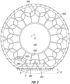
FIG. 2 shows the exemplary embodiment of the non-pneumatic wheel bearing upon a generallyflat surface 3, such as the ground, under an applied load L. Under the applied load L the tire deforms against theground 3 to form a contact patch which distributes the force across the ground. The displacement of the wheel D is shown in the figure by the dotted line 5 which represents the same tire in the unloaded state centered on the center axis of the wheel. As can be seen in the figure, the wheel under load is displaced upward at the top portion of the wheel resulting in the spokes in the upper portion of the wheel to be extended further and placed, therefore, under a greater tension than the spokes in the portion of the wheel that is immediately above the contact patch. - The
spokes 300 in the contact patch portion of thewheel 10 are have an effective length which is shorter in the spokes located elsewhere around the wheel. Theshear deforming members 350 are deformed, largely in shear, as the radiallyouter portion 370 of the spoke is moved toward thehub 100 and the radiallyinner portion 320 of the spoke is moved closer to theouter band 400 of thewheel 10 as the spokes move into the contact patch as the wheel rotates about its central axis. Theshear deforming members 350 on the side of the hub opposite to that of the contact patch shear in the opposite direction as theouter portion 370 of thespokes 300 are displaced away from thehub 100 and the effective length is extended. -
FIG. 3 shows a partial side view of a radially inner spokeportion 320 and an adjacent radially outer spokeportion 370 connected by ashear deforming member 350. Here, the spoke, 300, possesses a firstshear deforming member 351 connecting the radially outer spokeportion 370 to the radially inner spokeportion 320 and a secondshear deforming member 352 which connects the spoke to the adjacent spoke assembly. Alternatively, thespoke 300 may possess only oneshear deforming member 350. Alternatively, thespoke 300 may be connected by a plurality ofshear deforming members 350. Here the spoke radiallyinner portion 320, and spoke radiallyouter portion 370 possess a relatively high tensile modulus compared to the shear modulus of theshear deforming members 350 such that the majority of the extension of thespoke 300 occurs in shear in theshear deforming members 350. - The spokes radially
inner portion 320 andouter portion 370 may be constructed of a material having reinforcements embedded along the radial direction to prevent extension, or alternatively, or in addition, be constructed of a material having a relatively high tensile stiffness. In this embodiment, the spokes are constructed of a rubber embedded with a reinforcement which provides tensile stiffness. - In the current embodiment the
shear deforming members 350 are constructed from rubber and are symmetric about thespokes shear deforming members 350 here are depicted in a relaxed, unextended state. When the spokes are connected to the hub and outer band, the spokes are in a positive tension state. In the embodiment shown, when attached to thehub 100 andouter band 400 as shown inFIG 1 andFIG 2 , the spoke tension maintains a positive state throughout the rotation of the tire during the majority of rolling conditions, particularly when rolling over level ground under loads that are equal to or less than the maximum loads that the tire is designed to carry. - The
shear deforming members 350 in the embodiment shown possess a thickened middle section to prevent buckling. The thickness of theshear deforming member 350 is measured in the radial direction R and the length of the shear deforming member is measured in the circumferential direction C. -
FIG. 4 shows theshear deforming members 350 in an extended, positive shear state (solid lines) and in a relaxed or neutral shear state (dotted lines). Tension applied to the spokes, shown by the arrows T cause theshear deforming members 350 to shear as thespokes 300 to extend. The displacement between the undeformed state and the tensioned state may vary by design depending upon the designed use and loading conditions of the wheel. In the embodiment shown, the target displacement designed into the spoke assembly between the undeformed state and the pretensioned state is approximately equal to the maximum displacement D of the tire in the contact patch under normal loading conditions. -
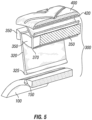
FIG. 5 shows an alternative embodiment of a partial perspective view ofspoke 300 attached at the radially outer spoke 370 to theouter band 400. This embodiment possesses acircumferential reinforcement 420 in theouter band 400. The radially inner spokeportion 320 in this embodiment are mechanically attached to thehub 100. The radially inner end of the radially inner spokeportion 320 has a thickenedportion 325 which engages a retainingslot 150 formed in thehub 100. -
FIG. 6 shows the embodiment of a partial perspective view ofspoke 300 attached to thehub 100. Here theshear deforming member 350 is extended in a positive shear state. The radially inner spoke portion is retained in thehub retaining slot 150. -
FIG. 7 shows an alternative embodiment having trapezoidalshear deforming members 350 attached to a reinforcedspoke structure outer structure 370 reinforcement is formed by a circumferentially continuous reinforcement that extends around theouter band 400 of the tire. The spoke structure reinforcement is attached to theouter band 400 at the inner surface of the outer band. Here, the spokes are made of a material such that their stiffness in tension is at least ten times the rubber block stiffness when in tension, and equal to or less than the rubber block stiffness when in compression. As an alternative to a continuous reinforcement, a fabric yarn type reinforcement could be woven circumferentially around the wheel such that in the axial direction a plurality of layers complete the spoke reinforcement. In at least one such alternative embodiment, one hundred layer of yarn, as measured along the axial direction, are woven circumferentially around the mold forming the radially outer spoke reinforcement. - The spoke radially
inner portions 320 may be connected to the hub by a mechanical connection, such as a slot and corresponding thickened radially inner end of the radially inner spokeportion 320. Alternatively, the radially inner spokeportion 320 may be attached to the hub by adhesive bonding. After assembly, the outer band, spokes, rubber blocks and hub are permanently mechanically linked as a mechanical unit. - As an alternative embodiment, the wheel possesses forty-five spoke units with a total of ninety shear deforming members and ninety connections with the outer band and forty-five spoke connections with the hub.
- Experimental tests using a finite element model of the spoke structure reveals a time domain response that is similar to that of a pneumatic tire. Vibration, noise and other impact forces are similar to that of pneumatic tires when the test was conducted at simulated velocities of 10 to 90 kilometers per hour.
-
FIG. 8 shows a computer model finite element test model of an embodiment of awheel 10 having forty-five spoke elements, ninetyshear deforming members 350 connected to theouter band 400. Here the outer band is shown to be compliant as it rolls over an obstacle, shown here as a cleat. The computed test results were compared then to test results from tires of other construction. -
FIG. 9 depicts the experimental data obtained from the computer model test of an embodiment having shear deforming spokes (SDP) and compared to data obtained from the experimental results of test tires having a similar size and designed for similar loading conditions, i.e.: passenger vehicle tires having roughly the same diameter and load carrying capacity. Each tire was loaded with an unsprung force of 4500 Newtons and driven over a cleat 4 at rotational velocities equivalent to a wheel traveling at 10 to 90 KPH at 10 KPH increments. The cleat 4 is a raised portion above theground surface 3 over which the tire rolls. The maximum additional force in the vertical direction Fz was measured and reported in Newtons. A non-pneumatic tire (NPP) with spokes connected to the hub at one end and the outer band at the other, a non-pneumatic tire with interconnected spokes (INP) with spokes having one connection to an adjacent spoke on either side, a hybrid non-pneumatic tire (HT1) having an air filled cavity similar to pneumatic tires having thickened sidewalls, a hybrid non-pneumatic tire (HT2) having an air filled cavity similar to pneumatic tires having reduced thickness sidewalls, a traditional non-pneumatic witness tire (WT2) inflated to 2.4 bar, a traditional non-pneumatic witness tire (WT3) inflated to 2.6 bar, and a traditional non-pneumatic witness tire (WT1) inflated to 2.1 bar were compared to the model of the embodiment of the non-pneumatic tire having shear deforming spokes (SDP). - The collected data demonstrated a surprising similar frequency response results for tires that have run over a finite element model cleat. The maximum additional force in the vertical direction Fz when the shear deforming spoke wheel (SDP) was rolled over a cleat was surprisingly similar to the maximum additional forces recorded with pneumatic tires (WT1, WT2, WT3) that were run over the cleat. It was particularly surprising that the maximum additional force in the vertical direction Fz of the shear deforming spoke wheel (SDP) model was noticeably less than that observed with non-pneumatic tires having spokes deforming in tension (NNP, INP) and closer to the values of the pneumatic tires (WT1, WT2, WT3), particularly at higher speeds.
- It should be understood that other web element configurations and geometries may be used within the scope of the embodiments, including web elements which possess multiple
shear deforming members 350 between the radially inner spokeportions 320 and the radially outer spokeportions 370, or multiple rows of web elements such that multiple laterally adjacent spokes may be present in the wheel. - While the present invention has been described in detail with respect to specific exemplary embodiments, it will be appreciated that those skilled in the art, upon attaining an understanding of the foregoing may readily produce alterations and variations of such embodiments.
Claims (14)
- , A non-pneumatic wheel (10) which rolls about a central axis, a radial direction (R) extending perpendicular to the central axis, and a circumferential axis extending perpendicular to the radial direction (R) and perpendicular to the central axis, the non-pneumatic wheel (10) possessing a compliant outer band (400) and an inner hub (100) and
at least one spoke (300) comprising:a first spoke portion (370) attached to the outer band (400), the first spoke portion (370) possessing a length in the radial direction (R) and a thickness extending in the circumferential direction (C);a second spoke portion (320) attached to the hub (100), the second spoke portion (320) possessing a length in the radial direction (R) and a thickness extending in the circumferential direction (C); andat least one shear deforming member (350, 351, 352) joining the first spoke portion (370) and the second spoke portion (320), the shear deforming member (350, 351, 352) possessing a thickness in the radial direction (R) and a length extending in the circumferential direction (C),the wheel (10) being characterized in that the at least one spoke (300) is pretensioned, wherein the spoke pretension creates a spoke displacement (D) from a neutral position to an extended position, where the neutral position is the position the spoke (300) would assume if it was not connected to the hub structure or the outer band and the tire is in an unloaded state. - . The non-pneumatic wheel (10) of claim 1 wherein the at least one spoke (300) further comprises a second shear deforming member (350, 351, 352) joining the first spoke portion (370) to the second spoke portion (320) of the adjacent spoke (300) such that each spoke (300) is joined to an adjacent spoke (300) by the second shear deforming member (350, 351, 352).
- . The non-pneumatic wheel (10) of claim 2 wherein the shear deforming members (350, 351, 352) of each of the spokes (300) form a continuous annular ring positioned around the hub (100).
- . The non-pneumatic wheel (10) of any of the above claims further comprising reinforcement embedded in the first spoke portion (370) and reinforcement embedded in the second spoke portion (320).
- . The non-pneumatic wheel (10) of any of the above claims wherein said shear deforming member (350, 351, 352) is a block of rubber.
- . The non-pneumatic wheel (10) of any of the above claims wherein each shear deforming member's thickness being greater at the midpoint between said first spoke portion (370) and said second spoke portion (320).
- . The non-pneumatic wheel (10) of any of the above claims wherein each shear deforming member (350, 351, 352) possesses a neutral shear state and an extended shear state the radial distance between the neutral shear state and the extended shear state equal to or greater than 20 mm.
- . The non-pneumatic wheel (10) of any of the above claims further comprising a circumferential reinforcement (420) embedded in the complaint outer band (400).
- . The non-pneumatic wheel (10) of any of the above claims wherein the second spoke portion (320) is mechanically attached to the hub (100).
- . The non-pneumatic wheel (10) of any of the above claims wherein the first spoke portion (370) is adhered to the outer band (400).
- . The non-pneumatic wheel (10) of claim 5 wherein the first spoke portion (370) and the second spoke portions (320) are made of a material such that the stiffness in tension is at least ten times the rubber block stiffness when in tension, and equal to or less than the rubber block stiffness when in compression.
- . The non-pneumatic wheel (10) of any of the above claims wherein the first spoke portion (370) thickness and the second poke portion (320) thickness are each less than the thickness of the shear deforming member (350).
- . The non-pneumatic wheel (10) of any of the above claims wherein said first spoke portion (370) is attached to the hub (100) by a first and second attachment to the hub (100), such that the spoke portion (370) has a Y-shaped lateral cross section.
- . The non-pneumatic wheel (10) of any of the above claims wherein the spoke pretension creates a spoke displacement (D) from a neutral position to an extended position that is equivalent to or greater than the displacement of the tire in the contact patch when it is loaded to the maximum load carrying capacity as specified by the manufacturer.
Applications Claiming Priority (2)
| Application Number | Priority Date | Filing Date | Title |
|---|---|---|---|
| PCT/US2015/068355 WO2017116481A1 (en) | 2015-12-31 | 2015-12-31 | Shear deforming non-pneumatic tire spokes |
| PCT/US2017/012047 WO2017117606A1 (en) | 2015-12-31 | 2017-01-03 | Shear deforming non-pneumatic tire spokes |
Publications (2)
| Publication Number | Publication Date |
|---|---|
| EP3397507A1 EP3397507A1 (en) | 2018-11-07 |
| EP3397507B1 true EP3397507B1 (en) | 2025-04-16 |
Family
ID=55221550
Family Applications (1)
| Application Number | Title | Priority Date | Filing Date |
|---|---|---|---|
| EP17700756.4A Active EP3397507B1 (en) | 2015-12-31 | 2017-01-03 | Non-pneumatic wheel |
Country Status (5)
| Country | Link |
|---|---|
| US (1) | US11090974B2 (en) |
| EP (1) | EP3397507B1 (en) |
| JP (1) | JP2019505432A (en) |
| CN (1) | CN108602381B (en) |
| WO (2) | WO2017116481A1 (en) |
Families Citing this family (23)
| Publication number | Priority date | Publication date | Assignee | Title |
|---|---|---|---|---|
| CA2915483C (en) | 2013-06-15 | 2021-11-16 | Ronald Thompson | Annular ring and non-pneumatic tire |
| WO2016126983A1 (en) | 2015-02-04 | 2016-08-11 | Advancing Mobility, Llc. | Non-pneumatic tire and other annular devices |
| WO2017106750A1 (en) | 2015-12-16 | 2017-06-22 | Thompson Ronald H | Track system for traction of a vehicle |
| KR101924107B1 (en) * | 2017-04-07 | 2018-11-30 | 금호타이어 주식회사 | Semi pneumatic tire |
| EP3638515B1 (en) | 2017-06-15 | 2023-04-05 | Camso Inc. | Wheel comprising a non-pneumatic tire |
| WO2019132911A1 (en) * | 2017-12-28 | 2019-07-04 | Compagnie Generale Des Etablissements Michelin | Method of manufacturing a spoke for a non-pneumatic tire |
| US11707947B2 (en) | 2018-06-14 | 2023-07-25 | Bridgestone Americas Tire Operations, Llc | Pre-strained non-pneumatic tire and method of making same |
| US20200055268A1 (en) * | 2018-08-20 | 2020-02-20 | The Goodyear Tire & Rubber Company | Tire curing system |
| CN109624605A (en) * | 2019-01-21 | 2019-04-16 | 浙江大学 | With damping structure and fractal structure without tire wheel |
| KR102103781B1 (en) * | 2019-06-10 | 2020-04-23 | 김민수 | Airless wheel |
| CN110667312B (en) * | 2019-11-14 | 2024-09-17 | 山东理工大学 | Shock-resistant non-pneumatic tire |
| CN110744973B (en) * | 2019-11-19 | 2024-08-20 | 厦门正新橡胶工业有限公司 | Inflation-free tyre |
| CN121246445A (en) | 2020-04-24 | 2026-01-02 | 米沃奇电动工具公司 | Wheel of vehicle |
| US20230173845A1 (en) * | 2020-04-30 | 2023-06-08 | Patrick F. King | Wheel comprising a non-pneumatic tire |
| CN111634154B (en) * | 2020-07-06 | 2024-08-16 | 山东科技大学 | Wheel with variable diameter and variable tread shape |
| US20220194129A1 (en) * | 2020-12-21 | 2022-06-23 | The Goodyear Tire & Rubber Company | Non-pneumatic tire and wheel assembly with reinforced spoke structure |
| US12600167B2 (en) * | 2020-12-22 | 2026-04-14 | Compagnie Generale Des Etablissements Michelin | Spoke for non-pneumatic tire with adhesion deflector and reinforcement layer |
| CN114654941A (en) * | 2020-12-23 | 2022-06-24 | 费曼科技(青岛)有限公司 | Inflation-free wheel and vehicle |
| CN113147265B (en) * | 2021-05-11 | 2022-05-10 | 季华实验室 | A kind of elastic gradient non-pneumatic tire and its manufacturing method |
| CN113580849B (en) * | 2021-07-09 | 2022-04-26 | 季华实验室 | Non-pneumatic tire and vehicle |
| US12263698B2 (en) * | 2021-08-17 | 2025-04-01 | Briggs & Riley Travelware Llc | Shock absorbing luggage wheel |
| US20240326516A1 (en) * | 2023-03-29 | 2024-10-03 | The Goodyear Tire & Rubber Company | Non-pneumatic tire with y-shaped spoke structure |
| CN117325587A (en) * | 2023-09-28 | 2024-01-02 | 广东粤港澳大湾区黄埔材料研究院 | Circumferential coupling shear spoke for non-pneumatic tire and tire |
Family Cites Families (24)
| Publication number | Priority date | Publication date | Assignee | Title |
|---|---|---|---|---|
| US482175A (en) * | 1892-09-06 | George hollafolla | ||
| US849095A (en) * | 1906-03-12 | 1907-04-02 | Arthur A Ambler | Vehicle-wheel. |
| FR883963A (en) * | 1941-07-31 | 1943-07-28 | Anonima Alfa Romeo Milano Napo | Spring wheel for road vehicles |
| US2492433A (en) * | 1944-10-28 | 1949-12-27 | James V Martin | Lightweight resilient tire |
| FR1124002A (en) * | 1948-09-28 | 1956-10-02 | G A Sa | Elastic device for suspensions, springs, brackets, wheels, etc. |
| US2869608A (en) | 1955-11-09 | 1959-01-20 | Palm Roy Inc | Spring wheel |
| US3018809A (en) * | 1959-11-10 | 1962-01-30 | Jules E Briche | Flexible non-pneumatic tire |
| WO1998043833A1 (en) * | 1997-03-27 | 1998-10-08 | Compagnie Generale Des Etablissements Michelin - Michelin & Cie | Non-pneumatic ductile tyre |
| DE69929903T2 (en) | 1999-12-10 | 2006-09-28 | Michelin Recherche Et Technique S.A. | ELASTIC SELF-WEARING TIRES |
| CA2458002C (en) | 2001-08-24 | 2010-08-17 | Michelin Recherche Et Technique S.A. | Non-pneumatic tire |
| US7013939B2 (en) | 2001-08-24 | 2006-03-21 | Michelin Recherche Et Technique S.A. | Compliant wheel |
| US6994134B2 (en) | 2001-10-05 | 2006-02-07 | Michelin Recherche Et Technique S.A. | Structurally supported resilient tire and materials |
| SE530394C2 (en) * | 2006-10-04 | 2008-05-20 | Sesyk Ab | Shock absorbing wheels |
| EP2177375A4 (en) * | 2007-07-31 | 2013-07-17 | Toyo Tire & Rubber Co | NON-PNEUMATIC TIRE AND METHOD FOR MANUFACTURING THE SAME |
| WO2010012091A1 (en) * | 2008-08-01 | 2010-02-04 | Mindmatter Innovates Inc. | Reactive planar suspension for a wheel |
| JP5221306B2 (en) * | 2008-11-28 | 2013-06-26 | 東洋ゴム工業株式会社 | Non-pneumatic tire |
| US9180732B2 (en) | 2009-08-28 | 2015-11-10 | Compagnie Generale Des Etablissements Michelin | Non-pneumatic wheel assembly with removable hub |
| FR2964597B1 (en) * | 2010-09-09 | 2012-08-31 | Michelin Soc Tech | NON-PNEUMATIC ELASTIC WHEEL |
| US9346499B2 (en) * | 2011-01-27 | 2016-05-24 | Irobot Corporation | Resilient wheel assemblies |
| WO2012171055A1 (en) | 2011-06-15 | 2012-12-20 | Vr Tek Wheels Pty Ltd | Non-pneumatic composite integrated tyre and wheel and method of fabrication thereof |
| KR101411103B1 (en) * | 2013-11-06 | 2014-06-27 | 한국타이어 주식회사 | Non-pneumatic tire |
| WO2016100017A1 (en) * | 2014-12-18 | 2016-06-23 | Bridgestone Americas Tire Operations, Llc | Tire with arched spokes |
| WO2017116384A1 (en) * | 2015-12-28 | 2017-07-06 | Campagnie Generale Des Etablissements Michelin | Method of forming non-pneumatic tire using support structure deformation |
| US20190375239A1 (en) * | 2016-12-21 | 2019-12-12 | Camso Inc. | Wheel comprising a non-pneumatic tire |
-
2015
- 2015-12-31 WO PCT/US2015/068355 patent/WO2017116481A1/en not_active Ceased
-
2017
- 2017-01-03 WO PCT/US2017/012047 patent/WO2017117606A1/en not_active Ceased
- 2017-01-03 EP EP17700756.4A patent/EP3397507B1/en active Active
- 2017-01-03 US US16/067,601 patent/US11090974B2/en active Active
- 2017-01-03 JP JP2018534815A patent/JP2019505432A/en not_active Abandoned
- 2017-01-03 CN CN201780009528.7A patent/CN108602381B/en active Active
Also Published As
| Publication number | Publication date |
|---|---|
| US20190009612A1 (en) | 2019-01-10 |
| WO2017117606A1 (en) | 2017-07-06 |
| EP3397507A1 (en) | 2018-11-07 |
| JP2019505432A (en) | 2019-02-28 |
| CN108602381A (en) | 2018-09-28 |
| WO2017116481A1 (en) | 2017-07-06 |
| CN108602381B (en) | 2021-12-10 |
| US11090974B2 (en) | 2021-08-17 |
Similar Documents
| Publication | Publication Date | Title |
|---|---|---|
| US11090974B2 (en) | Shear deforming non-pneumatic tire spokes | |
| US20210188008A1 (en) | Non-pneumatic tire and other annular devices | |
| EP1980420B1 (en) | Non-pneumatic tire | |
| EP3519204B1 (en) | Reinforced rubber spoke for a tire | |
| US11999419B2 (en) | Track system for traction of a vehicle | |
| US9493045B2 (en) | Method and apparatus for multilayer shear band reinforcement | |
| CA2525982C (en) | Non-pneumatic tire | |
| CA3047386C (en) | Wheel comprising a non-pneumatic tire | |
| EP3393771B1 (en) | Reinforcement structure for non-pneumatic wheel | |
| US20190009613A1 (en) | Non-pneumatic tire | |
| US20200276861A1 (en) | Wheel comprising a non-pneumatic tire | |
| US20170008342A1 (en) | Non-pneumatic tire including shear band | |
| CN106985601A (en) | Non-inflatable tyre | |
| MX2013010574A (en) | Non- pneumatic tire with annular spoke reinforcement. | |
| JP2018083620A (en) | Shear band for structurally supported tire | |
| JP6964470B2 (en) | Non-pneumatic tire | |
| RU2269425C2 (en) | Non-pneumatic tire | |
| EP3785931B1 (en) | Non-pneumatic looper tire |
Legal Events
| Date | Code | Title | Description |
|---|---|---|---|
| STAA | Information on the status of an ep patent application or granted ep patent |
Free format text: STATUS: UNKNOWN |
|
| STAA | Information on the status of an ep patent application or granted ep patent |
Free format text: STATUS: THE INTERNATIONAL PUBLICATION HAS BEEN MADE |
|
| PUAI | Public reference made under article 153(3) epc to a published international application that has entered the european phase |
Free format text: ORIGINAL CODE: 0009012 |
|
| STAA | Information on the status of an ep patent application or granted ep patent |
Free format text: STATUS: REQUEST FOR EXAMINATION WAS MADE |
|
| 17P | Request for examination filed |
Effective date: 20180703 |
|
| AK | Designated contracting states |
Kind code of ref document: A1 Designated state(s): AL AT BE BG CH CY CZ DE DK EE ES FI FR GB GR HR HU IE IS IT LI LT LU LV MC MK MT NL NO PL PT RO RS SE SI SK SM TR |
|
| AX | Request for extension of the european patent |
Extension state: BA ME |
|
| DAV | Request for validation of the european patent (deleted) | ||
| DAX | Request for extension of the european patent (deleted) | ||
| STAA | Information on the status of an ep patent application or granted ep patent |
Free format text: STATUS: EXAMINATION IS IN PROGRESS |
|
| 17Q | First examination report despatched |
Effective date: 20220127 |
|
| GRAP | Despatch of communication of intention to grant a patent |
Free format text: ORIGINAL CODE: EPIDOSNIGR1 |
|
| STAA | Information on the status of an ep patent application or granted ep patent |
Free format text: STATUS: GRANT OF PATENT IS INTENDED |
|
| INTG | Intention to grant announced |
Effective date: 20241107 |
|
| GRAS | Grant fee paid |
Free format text: ORIGINAL CODE: EPIDOSNIGR3 |
|
| GRAA | (expected) grant |
Free format text: ORIGINAL CODE: 0009210 |
|
| STAA | Information on the status of an ep patent application or granted ep patent |
Free format text: STATUS: THE PATENT HAS BEEN GRANTED |
|
| AK | Designated contracting states |
Kind code of ref document: B1 Designated state(s): AL AT BE BG CH CY CZ DE DK EE ES FI FR GB GR HR HU IE IS IT LI LT LU LV MC MK MT NL NO PL PT RO RS SE SI SK SM TR |
|
| REG | Reference to a national code |
Ref country code: GB Ref legal event code: FG4D |
|
| REG | Reference to a national code |
Ref country code: CH Ref legal event code: EP Ref country code: DE Ref legal event code: R096 Ref document number: 602017088924 Country of ref document: DE |
|
| REG | Reference to a national code |
Ref country code: IE Ref legal event code: FG4D |
|
| REG | Reference to a national code |
Ref country code: NL Ref legal event code: MP Effective date: 20250416 |
|
| PG25 | Lapsed in a contracting state [announced via postgrant information from national office to epo] |
Ref country code: NL Free format text: LAPSE BECAUSE OF FAILURE TO SUBMIT A TRANSLATION OF THE DESCRIPTION OR TO PAY THE FEE WITHIN THE PRESCRIBED TIME-LIMIT Effective date: 20250416 |
|
| REG | Reference to a national code |
Ref country code: AT Ref legal event code: MK05 Ref document number: 1785355 Country of ref document: AT Kind code of ref document: T Effective date: 20250416 |
|
| PG25 | Lapsed in a contracting state [announced via postgrant information from national office to epo] |
Ref country code: PT Free format text: LAPSE BECAUSE OF FAILURE TO SUBMIT A TRANSLATION OF THE DESCRIPTION OR TO PAY THE FEE WITHIN THE PRESCRIBED TIME-LIMIT Effective date: 20250818 Ref country code: FI Free format text: LAPSE BECAUSE OF FAILURE TO SUBMIT A TRANSLATION OF THE DESCRIPTION OR TO PAY THE FEE WITHIN THE PRESCRIBED TIME-LIMIT Effective date: 20250416 Ref country code: ES Free format text: LAPSE BECAUSE OF FAILURE TO SUBMIT A TRANSLATION OF THE DESCRIPTION OR TO PAY THE FEE WITHIN THE PRESCRIBED TIME-LIMIT Effective date: 20250416 |
|
| REG | Reference to a national code |
Ref country code: LT Ref legal event code: MG9D |
|
| PG25 | Lapsed in a contracting state [announced via postgrant information from national office to epo] |
Ref country code: GR Free format text: LAPSE BECAUSE OF FAILURE TO SUBMIT A TRANSLATION OF THE DESCRIPTION OR TO PAY THE FEE WITHIN THE PRESCRIBED TIME-LIMIT Effective date: 20250717 Ref country code: NO Free format text: LAPSE BECAUSE OF FAILURE TO SUBMIT A TRANSLATION OF THE DESCRIPTION OR TO PAY THE FEE WITHIN THE PRESCRIBED TIME-LIMIT Effective date: 20250716 |
|
| PG25 | Lapsed in a contracting state [announced via postgrant information from national office to epo] |
Ref country code: PL Free format text: LAPSE BECAUSE OF FAILURE TO SUBMIT A TRANSLATION OF THE DESCRIPTION OR TO PAY THE FEE WITHIN THE PRESCRIBED TIME-LIMIT Effective date: 20250416 |
|
| PG25 | Lapsed in a contracting state [announced via postgrant information from national office to epo] |
Ref country code: BG Free format text: LAPSE BECAUSE OF FAILURE TO SUBMIT A TRANSLATION OF THE DESCRIPTION OR TO PAY THE FEE WITHIN THE PRESCRIBED TIME-LIMIT Effective date: 20250416 |
|
| PG25 | Lapsed in a contracting state [announced via postgrant information from national office to epo] |
Ref country code: HR Free format text: LAPSE BECAUSE OF FAILURE TO SUBMIT A TRANSLATION OF THE DESCRIPTION OR TO PAY THE FEE WITHIN THE PRESCRIBED TIME-LIMIT Effective date: 20250416 |
|
| PG25 | Lapsed in a contracting state [announced via postgrant information from national office to epo] |
Ref country code: AT Free format text: LAPSE BECAUSE OF FAILURE TO SUBMIT A TRANSLATION OF THE DESCRIPTION OR TO PAY THE FEE WITHIN THE PRESCRIBED TIME-LIMIT Effective date: 20250416 |
|
| PG25 | Lapsed in a contracting state [announced via postgrant information from national office to epo] |
Ref country code: RS Free format text: LAPSE BECAUSE OF FAILURE TO SUBMIT A TRANSLATION OF THE DESCRIPTION OR TO PAY THE FEE WITHIN THE PRESCRIBED TIME-LIMIT Effective date: 20250716 |
|
| PG25 | Lapsed in a contracting state [announced via postgrant information from national office to epo] |
Ref country code: IS Free format text: LAPSE BECAUSE OF FAILURE TO SUBMIT A TRANSLATION OF THE DESCRIPTION OR TO PAY THE FEE WITHIN THE PRESCRIBED TIME-LIMIT Effective date: 20250816 |
|
| PG25 | Lapsed in a contracting state [announced via postgrant information from national office to epo] |
Ref country code: LV Free format text: LAPSE BECAUSE OF FAILURE TO SUBMIT A TRANSLATION OF THE DESCRIPTION OR TO PAY THE FEE WITHIN THE PRESCRIBED TIME-LIMIT Effective date: 20250416 |
|
| PG25 | Lapsed in a contracting state [announced via postgrant information from national office to epo] |
Ref country code: DK Free format text: LAPSE BECAUSE OF FAILURE TO SUBMIT A TRANSLATION OF THE DESCRIPTION OR TO PAY THE FEE WITHIN THE PRESCRIBED TIME-LIMIT Effective date: 20250416 Ref country code: SM Free format text: LAPSE BECAUSE OF FAILURE TO SUBMIT A TRANSLATION OF THE DESCRIPTION OR TO PAY THE FEE WITHIN THE PRESCRIBED TIME-LIMIT Effective date: 20250416 |
|
| REG | Reference to a national code |
Ref country code: DE Ref legal event code: R097 Ref document number: 602017088924 Country of ref document: DE |
|
| PG25 | Lapsed in a contracting state [announced via postgrant information from national office to epo] |
Ref country code: CZ Free format text: LAPSE BECAUSE OF FAILURE TO SUBMIT A TRANSLATION OF THE DESCRIPTION OR TO PAY THE FEE WITHIN THE PRESCRIBED TIME-LIMIT Effective date: 20250416 |
|
| PG25 | Lapsed in a contracting state [announced via postgrant information from national office to epo] |
Ref country code: EE Free format text: LAPSE BECAUSE OF FAILURE TO SUBMIT A TRANSLATION OF THE DESCRIPTION OR TO PAY THE FEE WITHIN THE PRESCRIBED TIME-LIMIT Effective date: 20250416 |
|
| PG25 | Lapsed in a contracting state [announced via postgrant information from national office to epo] |
Ref country code: SK Free format text: LAPSE BECAUSE OF FAILURE TO SUBMIT A TRANSLATION OF THE DESCRIPTION OR TO PAY THE FEE WITHIN THE PRESCRIBED TIME-LIMIT Effective date: 20250416 Ref country code: RO Free format text: LAPSE BECAUSE OF FAILURE TO SUBMIT A TRANSLATION OF THE DESCRIPTION OR TO PAY THE FEE WITHIN THE PRESCRIBED TIME-LIMIT Effective date: 20250416 |
|
| PG25 | Lapsed in a contracting state [announced via postgrant information from national office to epo] |
Ref country code: IT Free format text: LAPSE BECAUSE OF FAILURE TO SUBMIT A TRANSLATION OF THE DESCRIPTION OR TO PAY THE FEE WITHIN THE PRESCRIBED TIME-LIMIT Effective date: 20250416 |
|
| PLBE | No opposition filed within time limit |
Free format text: ORIGINAL CODE: 0009261 |
|
| STAA | Information on the status of an ep patent application or granted ep patent |
Free format text: STATUS: NO OPPOSITION FILED WITHIN TIME LIMIT |
|
| REG | Reference to a national code |
Ref country code: CH Ref legal event code: L10 Free format text: ST27 STATUS EVENT CODE: U-0-0-L10-L00 (AS PROVIDED BY THE NATIONAL OFFICE) Effective date: 20260225 |
|
| 26N | No opposition filed |
Effective date: 20260119 |
|
| PGFP | Annual fee paid to national office [announced via postgrant information from national office to epo] |
Ref country code: DE Payment date: 20260121 Year of fee payment: 10 |
|
| PGFP | Annual fee paid to national office [announced via postgrant information from national office to epo] |
Ref country code: FR Payment date: 20260123 Year of fee payment: 10 |