EP3397028A1 - Lighting system and related method of operating a lighting system - Google Patents
Lighting system and related method of operating a lighting system Download PDFInfo
- Publication number
- EP3397028A1 EP3397028A1 EP18169056.1A EP18169056A EP3397028A1 EP 3397028 A1 EP3397028 A1 EP 3397028A1 EP 18169056 A EP18169056 A EP 18169056A EP 3397028 A1 EP3397028 A1 EP 3397028A1
- Authority
- EP
- European Patent Office
- Prior art keywords
- lighting
- electronic
- lighting module
- electronic converter
- terminal
- Prior art date
- Legal status (The legal status is an assumption and is not a legal conclusion. Google has not performed a legal analysis and makes no representation as to the accuracy of the status listed.)
- Granted
Links
Images






Classifications
-
- H—ELECTRICITY
- H05—ELECTRIC TECHNIQUES NOT OTHERWISE PROVIDED FOR
- H05B—ELECTRIC HEATING; ELECTRIC LIGHT SOURCES NOT OTHERWISE PROVIDED FOR; CIRCUIT ARRANGEMENTS FOR ELECTRIC LIGHT SOURCES, IN GENERAL
- H05B45/00—Circuit arrangements for operating light-emitting diodes [LED]
- H05B45/30—Driver circuits
- H05B45/37—Converter circuits
- H05B45/3725—Switched mode power supply [SMPS]
-
- Y—GENERAL TAGGING OF NEW TECHNOLOGICAL DEVELOPMENTS; GENERAL TAGGING OF CROSS-SECTIONAL TECHNOLOGIES SPANNING OVER SEVERAL SECTIONS OF THE IPC; TECHNICAL SUBJECTS COVERED BY FORMER USPC CROSS-REFERENCE ART COLLECTIONS [XRACs] AND DIGESTS
- Y02—TECHNOLOGIES OR APPLICATIONS FOR MITIGATION OR ADAPTATION AGAINST CLIMATE CHANGE
- Y02B—CLIMATE CHANGE MITIGATION TECHNOLOGIES RELATED TO BUILDINGS, e.g. HOUSING, HOUSE APPLIANCES OR RELATED END-USER APPLICATIONS
- Y02B20/00—Energy efficient lighting technologies, e.g. halogen lamps or gas discharge lamps
- Y02B20/30—Semiconductor lamps, e.g. solid state lamps [SSL] light emitting diodes [LED] or organic LED [OLED]
Definitions
- the description refers to lighting systems.
- a lighting system typically comprises an electronic converter 10 and at least one lighting module 20.
- the electronic converter 10 may comprise an AC/DC or DC/DC switching power supply that receives a power supply input signal (for example, from the power line or a battery) and outputs a regulated voltage V out or a regulated current i out .
- a lighting module 20 comprises one or more light sources comprising, for example, at least one LED (Light Emitting Diode) or other solid-state lighting means, such as, for example, laser diodes.
- Figure 1 shows a lighting system, in which the electronic converter 10 is a current generator 10 C , i.e. the electronic converter 10 C provides a regulated current i out in output, by means of a positive terminal 100a and a negative terminal 100b, which represents a voltage reference.
- the electronic converter 10 is a current generator 10 C , i.e. the electronic converter 10 C provides a regulated current i out in output, by means of a positive terminal 100a and a negative terminal 100b, which represents a voltage reference.
- the lighting module 20 is, therefore, a module 20 C configured to be powered by a regulated current i out .
- Figure 2 shows an example of a lighting module 20 C .
- the lighting module 20 C comprises a positive input terminal 200a and a negative input terminal 200b for connecting to the terminals 100a and 100b of the electronic converter 10 C .
- the lighting module 20 C can be connected directly or through a cable to the electronic converter 10 C . Therefore, the terminal 200a is connected to the terminal 100a and the terminal 200b is connected to the terminal 100b, and the lighting module 20 therefore receives the current i out .
- the lighting module 20 C may comprise a chain or string of LEDs (LED chain or string) 22, in which a plurality of LEDs L is connected in series between the terminals 200a and 200b.
- the lighting module 20 C may also comprise a plurality of LED strings 22.
- the lighting module 20 C comprises means 24 configured to control the flow of current through the LEDs L, which allows adjustment of the brightness of the light emitted by the LEDs L, the so-called dimming function.
- these means 24 are implemented with one or more electronic switches 240, 242 and 244.
- the switch 240 can be connected (for example, directly) between the terminals 200a and 200b and thus allows short-circuiting of all the LEDs L of the lighting module 20 C , controlling, in this way, the overall brightness of the lighting module 20 C .
- the switches 242 and 244 may be connected in parallel with the respective LEDs L and they therefore enable a corresponding LED L to be shortcircuited, thereby individually controlling the brightness of the respective LED.
- the lighting module 20 C therefore comprises one or more additional terminals 200c for receiving one or more dimming control signals DCTRL.
- the received signal can be used to directly drive the means 24.
- a pulse width modulated (PWM) signal could be used to directly drive one of the switches 240, 242 or 244.
- PWM frequency is between 100 Hz and 2 kHz.
- the lighting module 20C may also comprise a control circuit 26 that receives the dimming control signal DCTRL and generates the signals for the means 24, for example, the switches 240, 242 and 244 as a function of the dimming control signal DCTRL.
- the control circuit 26 can drive one or more of the switches 240, 242 or 244 with a PWM signal, in which the working cycle of the PWM signal changes as a function of the dimming control signal DCTRL.
- the dimming control signal DCTRL can be any analog or digital signal capable of transmitting data that identify the required brightness of the lighting module 20 C and/or of the strings of LEDs 22 and/or of the individual LEDs L of the lighting module 20 C .
- the dimming control signal DCTRL is in accordance with the Digital Addressable Lighting Interface (DALI) protocol.
- DALI Digital Addressable Lighting Interface
- the electronic converter 10 C comprises a terminal 100c that supplies the dimming control signal(s) DCTRL for the lighting module 20 C .
- Figure 3 shows a lighting system, in which the electronic converter is a voltage generator 10 V and, similarly, the lighting module 20 is a module 20 V configured to be powered by a voltage.
- the electronic converter 10 V supplies a regulated voltage V out at the output, by means of a positive terminal 100a and a negative terminal 100b, which again represents a voltage reference.
- Figure 4 shows an example of a lighting module 20 V configured to be powered by a regulated voltage V out .
- the lighting module 20 V comprises a positive input terminal 200a and a negative input terminal 200b for connecting to the terminals 100a and 100b of the electronic converter 10 V .
- the lighting module 20V can be connected directly or through a cable to the electronic converter 10 V . Therefore, the terminal 200a is connected to the terminal 100a and the terminal 200b is connected to the terminal 100b, and the lighting module 20 therefore receives the voltage V out .
- the lighting module 20 V is an LED module comprising a string of LEDs 22 connected between the terminals 200a and 200b.
- the LEDs L can also be divided over several branches connected in parallel.
- the module 20 V may comprise a first LED string 22a comprising a first set of LEDs L connected in series and a second string of LEDs 22b comprising a second set of LEDs L connected in series.
- the lighting module 20 V Since the lighting module 20 V is supplied with a voltage, the lighting module 20 V also comprises means 24 for regulating the current flowing through each string of LEDs 22.
- the first LED string 22a and a first current regulator 24a are connected (for example, directly) in series between the terminals 200a and 200b, and the second string of LEDs 22b and a second current regulator 24b are connected (for example, directly) in series between the terminals 200a and 200b. Therefore, in the example considered, the strings 22a and 22b are powered by means of a common voltage ( V out ).
- the current regulator 24 can be a resistor or a linear current regulator.
- the current regulator 24 can also be implemented with current mirrors or with a switched mode current source, typically comprising an inductor and an electronic switch.
- the lighting module 20 V can comprise one or more additional terminals 200c for receiving one or more dimming control signals DCTRL.
- the received signal can be used for directly driving the means 24.
- a pulse width modulated (PWM) signal could be used to turn a respective current regulator on or off.
- the lighting module 20 V may comprise a control circuit 26 that receives the dimming control signal DCTRL and generates the signals for the means 24 as a function of the dimming control signal DCTRL.
- the control circuit 26 can turn the current regulators 24 on or off with a PWM signal or set the reference current of a linear or switching current regulator.
- the dimming control signal DCTRL can be any analog or digital signal capable of transmitting data that identify the required brightness of the lighting module 20 V and/or of the strings of LEDs 22 and/or of the individual LEDs L of the lighting module 20 V .
- the dimming control signal DCTRL is in accordance with the Digital Addressable Lighting Interface (DALI) protocol.
- DALI Digital Addressable Lighting Interface
- a lighting module 20 has associated a specific maximum power supply P Max , which, for example, depends on the type and number of LED Ls that are included in the lighting module 20.
- the electronic converter 10 should, therefore, be able to provide at least the maximum power supply P Max .
- the actual power supply (average) P may be less than the maximum power supply P Max reducing (by the means 24) the current flowing through the LEDs L of the lighting module 20.
- Figures 5 and 6 show two possible solutions for supplying power to a plurality of lighting modules.
- Figure 5 shows a solution, in which an electronic converter 10 C supplies a plurality of lighting modules 20 C , for example two modules 20 C1 and 20 C2 .
- the lighting modules 20 C are typically connected in series. Therefore, the terminal 200a of the first lighting module 20 C1 is connected (for example, directly) to the terminal 100a of the electronic converter 10 C , the terminal 200a of the second lighting module 20 C2 is connected (for example, directly) to the terminal 200b of the first lighting module 20 C1 and the terminal 200b of the second lighting module 20 C2 is connected (for example, directly) to the terminal 100b of the electronic converter 10 C .
- a control circuit 12 is used for generating the dimming control signals that are sent to the terminals 200c of the lighting modules 20 C .
- the control circuit 12 can also be integrated in the electronic converter 10 C .
- Figure 6 shows a solution in which an electronic converter 10 V supplies power to a plurality of lighting modules 20 V , for example, two modules 20 V1 and 20 V2 .
- the lighting modules 20 V are typically connected in parallel. Therefore, the terminal 200a of the first lighting module 20 C1 and the terminal 200a of the second lighting module 20 C2 are connected (for example, directly) to the terminal 100a of the electronic converter 10 C , and the terminal 200b of the first lighting module 20 C1 and the terminal 200b of the second lighting module 20 C2 are connected (for example, directly) to the terminal 100b of the electronic converter 10 C .
- a control circuit 12 is provided, which generates the dimming control signals that are sent to the terminals 200c of the lighting modules 20 C .
- each lighting module 20 has associated a respective maximum power supply P Max and the electronic converter 10 should be able to provide a power supply that corresponds to at least the sum of the maximum power supply capacities of the various lighting modules 20 connected to the electronic converter.
- Figures 7 and 8 illustrate additional solutions that can be used to supply power to a plurality of lighting modules 20.
- FIG. 7 shows an example in which each lighting module 20 (i.e. 20 V or 20 C ) is supplied by means of a respective electronic converter 10.
- each lighting module 20 i.e. 20 V or 20 C
- three lighting modules 20 1 , 20 2 and 20 3 are shown, which are supplied by means of three generators 10 1 , 10 2 and 10 3 , such as "buck" converters.
- the electronic converters 10 can provide a regulated voltage or, preferably, a regulated current.
- each converter 10 can individually control the operation of the respective lighting module 20.
- each converter 10 can carry out a dimming operation by adjusting the average current that passes through the lighting module 20, for example, by adjusting the amplitude of the current (in the case in which the converters 10 are current generators) and/or by switching on/off the respective lighting module 20, for example, by using a pulse width modulation (PWM) signal.
- PWM pulse width modulation
- the frequency of the PWM (for example, between 100 Hz and 2 kHz) is low with respect to the switching frequency of the electronic converter 10 (for example, between 10 and 100 kHz).
- the electronic converters 10 1 , 10 2 and 10 3 can also use the same rectifier circuit 30 and/or an additional electronic converter 32, such as a converter with correction of the power factor, can be used to provide the power supply, such as, for example, a regulated voltage V Bus , to the electronic converters 10 1 , 10 2 and 10 3 .
- an additional electronic converter 32 such as a converter with correction of the power factor, can be used to provide the power supply, such as, for example, a regulated voltage V Bus , to the electronic converters 10 1 , 10 2 and 10 3 .
- each electronic converter 10 can have a low power, i.e. that of the respective lighting module 20. Furthermore, malfunctioning of a single lighting module 20 or electronic converter 10 does not typically affect the operation of the other lighting modules 20 and electronic converters 10.
- Figure 8 shows a solution in which the lighting modules 20, for example, again three lighting modules 20 1 , 20 2 and 20 3 , are selectively connected to the same electronic converter 10, i.e. the lighting modules 20 are selectively supplied with power.
- a solution of this type is described in the American patent application US 2010/0295472 A1 or in the Italian patent application IT102016000080749 , the contents of which are incorporated herein by reference.
- the electronic converter 10 supplies several branches, one for each lighting module 20.
- each branch is associated a respective lighting module 20 and an electronic switch SW. Therefore, for the exemplary case of three lighting modules 20 1 , 20 2 and 20 3 , there are three electronic switches SW 1 , SW 2 and SW 3 . These switches SW are controlled in such a way as to selectively connect the lighting modules 20 to the electronic converter 10.
- each lighting module 20 may also have associated a capacitor (C 1 , C 2 and C 3 ), which stabilizes the power supplied to the lighting module 20.
- the converter 10 is a current generator (see document US 2010/0295472 A1 )
- only one of the branches is connected to the electronic converter 10, i.e. only one of the switches SW 1 , SW 2 and SW 3 is closed during a certain time interval. Therefore, by sequentially activating the switches SW, the lighting modules 20 1 , 20 2 and 20 3 can be supplied alternately.
- the converter 10 also has associated, in this case, a protection circuit configured to protect the electronic converter in the event that no lighting module 20 is connected to the output of the electronic converter 10.
- a plurality of lighting modules 20 can also be connected simultaneously to the electronic converter 10 (respecting the maximum power capacity that the electronic converter 10 can provide).
- the dimming operation can be performed by adjusting the duration during which each lighting module 20 is connected to the electronic converter 10.
- This solution therefore, has the advantage that only a single electronic converter is required 10.
- this converter 10 must be able to supply power to all the lighting modules 20.
- the operating time of each lighting module may become too short.
- the present description aims to provide solutions for powering a plurality of lighting modules.
- this object is achieved thanks to a lighting system having the characteristics referred to in the following claims.
- the claims also concern a relative method for operating a lighting system.
- the lighting system comprises a plurality of electronic converters and a plurality of lighting modules.
- the lighting system further comprises switching means configured for connecting the lighting modules to the electronic converters.
- the switching means allow at least two switching states. In the first switching state, at least one lighting module is connected to each electronic converter. Instead, in the second switching state, at least one electronic converter is disconnected, and the lighting module(s) connected during the first switching state to this at least one electronic converter are connected to the other electronic converters.
- the lighting system also comprises a control circuit configured to detect one or more signals indicative of the supply powers required/requested by the lighting modules.
- the control circuit can drive the switching of the switching means to activate the first or second switching state according to the supply powers required by the lighting modules.
- control circuit can determine the sum of the supply powers required by the lighting modules and, in the event that the sum is greater than a first threshold, activate the first switching state. On the other hand, if the sum is less than a second threshold, the control circuit can activate the second switching state.
- the efficiency of the system is increased, since, instead of operating multiple electronic converters at a low efficiency, a smaller number of electronic converters are used that operate at a higher efficiency.
- the power supply required by the lighting modules may vary as a result of a dimming operation.
- one or more lighting modules may comprise adjustment means configured to vary the supply power required by the respective lighting module as a function of one or more dimming control signals.
- the adjustment means can be configured to adjust the amplitude of the current flowing through the respective lighting module as a function of the dimming control signals.
- the adjustment means may modulate the current flowing through the respective lighting module with a pulse width modulation. In this case, the modulations can also be synchronized in such a way as to sequentially turn on the lighting modules connected to each electronic converter.
- control circuit can, therefore, detect the power supply required by the lighting modules by monitoring these dimming control signals.
- an embodiment in the context of this description indicates that a particular configuration, structure or characteristic described in relation to the embodiment is included in at least one embodiment. Therefore, phrases such as "in an embodiment”, possibly present in different places of this description do not necessarily refer to the same embodiment. Moreover, particular configurations, structures or characteristics can be combined in any convenient way in one or more embodiments.
- the present description provides solutions for powering a plurality of lighting modules 20.
- the inventors have observed that in the solutions described with reference to Figures 5 to 8 , there are often situations in which the actual load does not exploit the maximum power capacity of the electronic converter(s) 10.
- the lighting modules 20 can be operated in the dimming mode, in which the power supply is less than the maximum power.
- Figure 9 shows a first embodiment of a lighting system capable of overcoming such problems.
- the system comprises switching means 40 connected between the electronic converters 10 and the lighting modules 20. These switching means 40 are configured to selectively connect the lighting modules 20 to the electronic converters 10.
- the switching means 40 are configured for:
- the first case a) corresponds substantially to the connection described with reference to Figure 7 , in which each electronic converter 10 supplies a respective lighting module 20. Therefore, in various embodiments, the first electronic converter 10 1 is configured to provide a power supply that corresponds to the maximum power supply of the lighting module 20 1 . Similarly, the second electronic converter 10 2 can be configured to provide a power supply that corresponds to the maximum power supply of the lighting module 20 2 .
- the second case b) corresponds to the connection described with reference to Figures 5 and 6 , in which a single electronic converter 10 supplies a plurality of lighting modules 20.
- the electronic converter 10 1 is not able to provide a power supply that corresponds to the sum of the maximum power supply capacities of the lighting modules 20 1 and 20 2 . Therefore, in various embodiments, this mode is only activated when the lighting modules 20 1 and 20 2 are operated with the dimming operation, and the sum of the supply powers currently required by lighting modules 20 1 and 20 2 is less than or equal to the power supply that the electronic converter 10 1 is able to supply. In this case, the second electronic converter 10 2 is, therefore, unused and can be switched off or put into a low-power mode (stand-by). As a result, the efficiency of the system is increased, since, instead of operating two electronic converters at a low efficiency, a single converter 10 1 is used that operates with a greater efficiency.
- the lighting modules 20 allow the brightness to be adjusted.
- the lighting modules 20, such as, for example, LED lighting modules can comprise a terminal 200c for receiving at least one dimming control signal DCTRL, which in general can be an analog or digital signal. Therefore, the relative description applies fully.
- DCTRL dimming control signal
- the dimming control signal(s) DCTRL are generated by means of a dimming control circuit 12, such as for example an analog and/or digital circuit, such as, for example, a microprocessor programmed by code.
- a dimming control circuit 12 such as for example an analog and/or digital circuit, such as, for example, a microprocessor programmed by code.
- a single BUS connection and a communication protocol e.g. DALI
- each lighting module 20 may comprise a control circuit 26 that generates the control signal(s) for the respective adjustment means 24 as a function of the dimming control signal DCTRL, which includes its identifier.
- control circuit 12 can also directly generate the control signals for the adjustment means 24 of the lighting modules 20.
- the system also comprises a control circuit 42, such as, for example, an analog and/or digital circuit, such as for example a microprocessor programmed by means of software code, which generates one or more control signals SCTRL for the switching means 40 as a function of the power supply required by the lighting modules 20.
- a control circuit 42 such as, for example, an analog and/or digital circuit, such as for example a microprocessor programmed by means of software code, which generates one or more control signals SCTRL for the switching means 40 as a function of the power supply required by the lighting modules 20.
- the circuits 12 and 42 may also be implemented within the same control circuit, for example, the microprocessor itself.
- control circuit 42 can, therefore, monitor one or more signals indicative of the supply powers P20 1 and P20 2 required by the lighting modules 20 1 and 20 2 , such as, for example:
- control circuit 42 is configured for:
- switching between the two operating modes can also occur with a hysteresis, i.e. the control circuit 42 can use an upper threshold for activating mode a) and a different lower threshold for activating mode b).
- the specific implementation of the means 40 depends on the number of electronic converters 10, on the number of lighting modules 20, and on the type of power supply used (regulated voltage or current).
- Figure 10 shows an embodiment in which each electronic converter 10 supplies a regulated voltage, such as, for example, 12, 24 or 48 VCC.
- a regulated voltage such as, for example, 12, 24 or 48 VCC.
- two electronic converters 10 v1 and 10 v2 and two lighting modules 20 v1 and 20 v2 are shown.
- the terminals 200a and 200b of the first lighting module 20 V1 are connected (for example, directly) to the terminals 100a and 100b of the first electronic converter 10 V1 .
- the switching means 40 comprise two multiplexers 402 1 and 402 2 configured to respectively connect the terminals 200a and 200b of the second lighting module 20 V2 to the terminals 100a and 100b of the first electronic converter 10 V1 or of the second electronic converter 10 V2 .
- control circuit 42 drives the multiplexers 402 1 and 402 2 so as to:
- control circuit 42 makes the selection on the basis of the supply powers P20 1 and P20 2 currently and/or on average required by lighting modules 20 V1 and 20 V2 .
- Figure 11a shows an example for the supply powers P20 1 and P20 2 required by the lighting modules 20 V1 and 20 V2 , and the supply powers P10 1 and P10 2 supplied by the electronic converters 10 V1 and 10 V2 .
- the lighting modules 20 V1 and 20 V2 implement the dimming function by lowering the amplitude of the current flowing through its own current regulator 24.
- the lighting module 20 V is then configured to adjust the amplitude of the current passing through the lighting module and hence the instantaneous value of the required power supply.
- both lighting modules 20 V1 and 20 V2 require the maximum power supply and are therefore supplied individually.
- the current passing through the lighting modules 20 V1 and 20 V2 is lowered, for example, the supply powers, P10 1 and P10 2 are reduced to 70% and 80%.
- the sum of the supply powers is greater than that which the electronic converter 10 V1 can provide.
- the current passing through the lighting modules 20 V1 and 20 V2 is lowered even further, for example, the supply powers, P10 1 and P10 2 are reduced to 40% and 50%. Therefore, the sum of the supply powers is now lower than that which the electronic converter 10 V1 can provide, and the control circuit 42 drives the switching means 40 in such a way that both the lighting modules 20 V1 and 20 V2 are supplied by means of the electronic converter 10 V1 .
- Figure 11b shows the case in which the lighting modules 20 V1 and 20 V2 implement the dimming function by means of a PWM, i.e. by switching on and switching off the light sources of the lighting module.
- the supply powers P10 1 and P10 2 are reduced, on average, to 70% and 80% at a time t 1 and to 40% and 50% at a time t 2 . Therefore, up to the time t 2 , the lighting modules 20 V1 and 20 V2 are supplied separately and can independently perform the dimming function. Instead, at least from the time t 2 , i.e. from the moment that the lighting modules 20 1 and 20 2 are powered by the same electronic converter 10 V1 , the dimming function of the lighting modules 20 V1 and 20 V2 should be synchronized, so as to switch on only one of the lighting modules 20 V1 and 20 V2 at a time (similar to that described with reference to Figure 8 ).
- the synchronization can be controlled by means of the control circuit 12 or 42.
- the control circuit 12 could directly generate PWM signals usable for driving the dimming function of the lighting modules 20 V1 and 20 V2 .
- Figure 12 shows a second embodiment.
- the electronic converters 10 V1 and 10 V2 use the same voltage reference, i.e. the terminal 100b of the first electronic converter 10 V1 is connected (for example, directly) to the terminal 100b of the second electronic converter 10 V2 .
- this connection is typically already provided in the case in which the electronic converters 10 V1 and 10 V2 are non-isolated converters which are fed through a common rectifier circuit 30 and possibly an electronic converter 32, such as, for example, a converter with correction of the power factor that supplies a regulated voltage V BUS .
- the second multiplexer is therefore superfluous.
- the terminals 200a and 200b of the first lighting module 20 V1 are connected (for example, directly) to the terminals 100a and 100b of the first electronic converter 10 V1 .
- the terminal 200b of the second lighting module 20 V2 is connected (for example, directly) to the terminal 100b of the second electronic converter 10 V2 , and consequently to the terminal 100b of the first electronic converter 10 V1 .
- the switching means 40 comprise one multiplexer 402 configured to connect the terminal 200a of the second lighting module 20 V2 to the terminal 100a of the first electronic converter 10 V1 or of the second electronic converter 10 V2 .
- Figure 13 shows a possible implementation of the multiplexer 402 with two electronic switches SW1 and SW2.
- the first electronic switch SW1 is connected between the terminal 200a of the second lighting module 20 V2 and the terminal 100a of the first electronic converter 10 V1
- the second electronic switch SW2 is connected between the terminal 200a of the second lighting module 20 V2 and the terminal 100a of the second electronic converter 10 V2 .
- the solution described here can also be applied in the case in which the electronic converters 10 provide a regulated current.
- Figure 14 shows an embodiment comprising two lighting modules 20 C1 and 20 C2 , and two electronic converters 10 C1 and 10 C2 , which use the same voltage reference.
- the terminal 200a of the first lighting module 20 C1 is connected (for example, directly) to the terminal 100a of the first electronic converter 10 C1 and the terminal 200b of the second lighting module 20 C2 is connected (for example, directly) to the terminal 100b of the second electronic converter 10 C2 .
- a first electronic switch S1b is connected between the terminal 200b of the first lighting module 20 C1 and the terminal 100b of the first electronic converter 10 C1
- a second electronic switch S2a is connected between the terminal 200a of the second lighting module 20 C2 and the terminal 100a of the second electronic converter 10 C2 .
- a third electronic switch SL12 is connected between the terminal 200b of the first lighting module 20 C1 and the terminal 200a of the second lighting module 20 C2 .
- the switches S1b and SL12 or alternatively, the switches S2a and SL12, can be part of a multiplexer.
- control circuit 42 can drive the switches S1b, S2a and SL12 so as to:
- case a) corresponds substantially to that described with reference to Figure 7 and the case b) corresponds substantially to the connection described with reference to Figure 5 .
- the control circuit 42 makes the selection based on the supply powers P20 1 and P20 2 required by the lighting modules 20 C1 and 20 C2 .
- the lighting modules 20 C1 and 20 C2 can modulate the amplitude of the power supply required (for example, by switching off certain LEDs) or can modulate the power supply required with a PWM.
- the dimming function is preferably synchronized.
- the electronic switches S1b, S2a and SL12 can also be used for other purposes, for example, in cases of malfunction to disconnect one or more of the lighting modules 20 C1 and 20 C2 .
- the control circuit 42 can drive the electronic switches S1, S2 and SL1 at least with the following switching states: S1b S2a SL12 powered modules 10 C1 10 C2 1 1 0 20 C1 20 C2 0 0 1 20 C1 , 20 C2 - 0 1 0 - 20 C2 1 0 0 20 C1 0 0 0 - - wherein "1" indicates that the switch is closed and "0" indicates that the switch is open, i.e.:
- the lighting modules 20 C1 and 20 C2 can also be connected in parallel to the electronic converter 10 C1 .
- Figure 15 shows an embodiment in which the terminals 200a and 200b of the first lighting module 20 C1 are connected (for example, directly) to the terminals 100a and 100b of the first electronic converter 10 C1 .
- the terminal 200b of the second lighting module 20 C2 is connected (for example, directly) to the terminal 100b of the second electronic converter 10 C2 , and consequently to the terminal 100b of the first electronic converter 10 C1 .
- a first electronic switch Sw1 is connected between the terminal 200a of the second lighting module 20 C2 and the terminal 100a of the first electronic converter 10 C1
- the second electronic switch SW2 is connected between the terminal 200a of the second lighting module 20 C2 and the terminal 100a of the second electronic converter 10 C2 .
- control circuit 42 can drive the switches SW1 and SW2 so as to:
- case b) corresponds substantially to the connection described with reference to Figure 8 , in which the lighting modules 20 and the control circuit 12 are configured to implement the dimming function by sequentially switching on the lighting modules 20 C1 and 20 C2 .
- the switching means 40 are configured to selectively connect:
- control circuit 42 monitors signals identifying the supply powers P20 1 and P20 2 required by the lighting modules 20 1 and 20 2 and drives the switching means 40 as a function of these signals.
- the switching means 40 can be configured to connect both lighting modules 20 1 and 20 2 to the first electronic converter 10 1 and/or to the second electronic converter 10 2 .
- this is more useful in the case in which the electronic converters 10 1 and 10 2 support different maximum power supply capacities or if one of the electronic converters 10 1 and 10 2 fails.
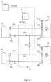
- Figure 16 shows a possible embodiment in which two lighting modules 20 C1 and 20 C2 can be connected in series to a first electronic converter 10 C1 or to a second electronic converter 10 C2 .
- the switching means 40 comprise:
- some of the switches may be part of a multiplexer.
- the switching means 40 are configured to selectively connect:
- the lighting modules 20 are then connected in series. However, as described above, in various embodiments, the lighting modules 20 can be connected in parallel.
- the lighting system may also comprise a greater number of lighting modules 20 and/or electronic converters 10.
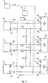
- Figure 17 shows an embodiment, in which the lighting system comprises the lighting modules 20 C1 , 20 C2 and 20 C3 and three electronic converters 10 C1 , 10 C2 and 10 C3 .
- the switching means 40 comprise:
- the control circuit 42 can drive the electronic switches S1b, S2a, S2b, S3a, SL12, SL13 and SL23 at least with the following switching states:
- the electronic switches can also be used for other purposes, for example - in cases of malfunction - to disconnect one or more of the lighting modules 20 C1 , 20 C2 and 20 C3 , for example, to disconnect the lighting module 20 C1 :
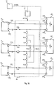
- FIG 18 shows that additional electronic switches can also be added, such as, for example:
- the electronic switches SL12, SL13 and SL23 represent an interconnection network between the lighting modules 20 and the electronic switches S1b, S2a, S2b and S3a (and possibly the switches S1a and S3b) represent switching means for connecting the electronic converters 10 to the lighting modules 20 as connected through the interconnection network.
- the interconnection network can, therefore, be implemented according to the specific application.
- Figure 19 shows an embodiment, in which the interconnection network is made with five electronic switches:
- Figure 20 shows an embodiment, in which the interconnection network is made with eight electronic switches:
- the interconnection means 40 can be produced by meshed point-to-point topologies, in which each element of the network is directly connected to each other (for example, as in the circuit of Figure 18 ), but also by means of star-type topologies, in which the branches of the network converge on the same point/subnetwork and are then sorted. In fact, by increasing the number of nodes in the network, a star topology may be more convenient.
- the lighting system comprises at least two electronic converters 10 and at least two lighting modules 20, such as, for example LED modules.
- the system further comprises switching means 40 configured for connecting the lighting modules 20 to the electronic converters 10.
- the switching means 40 are configured to allow at least two switching states.
- the lighting system further comprises a control circuit 42 configured to drive the switching of the switching means 40.
- control circuit monitors the sum of the supply powers (average and/or instantaneous) required by the lighting modules and activates the first or second switching state according to the sum of the supply powers.
- control circuit 42 controls the switching means 40 so as to:
- the switching means can also support further switching states and the control circuit 42 can be configured to select one of the switching states according to the power requirements required by the lighting modules 20.
- the electronic converters 10 may have substantially the same characteristics. In particular, in the case in which the electronic converters 10 are current generators, these generators substantially provide the same regulated current i out . Similarly, in the case in which the electronic converters 10 are voltage generators, these generators provide substantially the same regulated voltage V out .
- the lighting modules 20 are also of the same type, i.e. modules configured to be supplied with the same regulated voltage or the same regulated current.
- the maximum power supply of the lighting modules 20 may also be different from one another, for example, the lighting modules 20 may comprise a different number of LEDs L.
- the lighting modules 20 have the same characteristics, in particular, with reference to the maximum power supply.
- each lighting module 20 comprises the same number of LEDs L.
- the electronic converters can be configured to provide the same maximum power supply.
Landscapes
- Circuit Arrangement For Electric Light Sources In General (AREA)
Abstract
Description
- The description refers to lighting systems.
- A lighting system typically comprises an
electronic converter 10 and at least onelighting module 20. For example, theelectronic converter 10 may comprise an AC/DC or DC/DC switching power supply that receives a power supply input signal (for example, from the power line or a battery) and outputs a regulated voltage Vout or a regulated current iout . Alighting module 20 comprises one or more light sources comprising, for example, at least one LED (Light Emitting Diode) or other solid-state lighting means, such as, for example, laser diodes. - For example,
Figure 1 shows a lighting system, in which theelectronic converter 10 is acurrent generator 10C, i.e. theelectronic converter 10C provides a regulated current iout in output, by means of a positive terminal 100a and anegative terminal 100b, which represents a voltage reference. - The
lighting module 20 is, therefore, amodule 20C configured to be powered by a regulated current iout . For example,Figure 2 shows an example of alighting module 20C. In particular, thelighting module 20C comprises a positive input terminal 200a and anegative input terminal 200b for connecting to theterminals 100a and 100b of theelectronic converter 10C. For example, thelighting module 20C can be connected directly or through a cable to theelectronic converter 10C. Therefore, the terminal 200a is connected to the terminal 100a and theterminal 200b is connected to theterminal 100b, and thelighting module 20 therefore receives the current iout. - For example, the
lighting module 20C may comprise a chain or string of LEDs (LED chain or string) 22, in which a plurality of LEDs L is connected in series between theterminals 200a and 200b. In general, thelighting module 20C may also comprise a plurality ofLED strings 22. - In the example considered, the
lighting module 20C comprises means 24 configured to control the flow of current through the LEDs L, which allows adjustment of the brightness of the light emitted by the LEDs L, the so-called dimming function. - For example, in
Figure 2 , these means 24 are implemented with one or moreelectronic switches switch 240 can be connected (for example, directly) between theterminals 200a and 200b and thus allows short-circuiting of all the LEDs L of thelighting module 20C, controlling, in this way, the overall brightness of thelighting module 20C. Instead, theswitches - In the example considered, the
lighting module 20C therefore comprises one or more additional terminals 200c for receiving one or more dimming control signals DCTRL. In the simplest case, the received signal can be used to directly drive themeans 24. For example, a pulse width modulated (PWM) signal could be used to directly drive one of theswitches - In general, the lighting module 20C may also comprise a
control circuit 26 that receives the dimming control signal DCTRL and generates the signals for themeans 24, for example, theswitches control circuit 26 can drive one or more of theswitches - Therefore, in general, the dimming control signal DCTRL can be any analog or digital signal capable of transmitting data that identify the required brightness of the
lighting module 20C and/or of the strings ofLEDs 22 and/or of the individual LEDs L of thelighting module 20C. For example, in various embodiments, the dimming control signal DCTRL is in accordance with the Digital Addressable Lighting Interface (DALI) protocol. - For example, in
Figure 1 , theelectronic converter 10C comprises a terminal 100c that supplies the dimming control signal(s) DCTRL for thelighting module 20C. - Instead,
Figure 3 shows a lighting system, in which the electronic converter is avoltage generator 10V and, similarly, thelighting module 20 is amodule 20V configured to be powered by a voltage. - Therefore, in
Figure 3 , theelectronic converter 10V supplies a regulated voltage Vout at the output, by means of a positive terminal 100a and anegative terminal 100b, which again represents a voltage reference. -
Figure 4 shows an example of alighting module 20V configured to be powered by a regulated voltage Vout . In particular, thelighting module 20V comprises a positive input terminal 200a and anegative input terminal 200b for connecting to theterminals 100a and 100b of theelectronic converter 10V. Also in this case, the lighting module 20V can be connected directly or through a cable to theelectronic converter 10V. Therefore, the terminal 200a is connected to the terminal 100a and theterminal 200b is connected to theterminal 100b, and thelighting module 20 therefore receives the voltage Vout . - In the example considered, the
lighting module 20V is an LED module comprising a string ofLEDs 22 connected between theterminals 200a and 200b. In general, the LEDs L can also be divided over several branches connected in parallel. For example, as shown inFigure 4 , themodule 20V may comprise a first LED string 22a comprising a first set of LEDs L connected in series and a second string of LEDs 22b comprising a second set of LEDs L connected in series. - Since the
lighting module 20V is supplied with a voltage, thelighting module 20V also comprisesmeans 24 for regulating the current flowing through each string ofLEDs 22. For example, inFigure 4 , the first LED string 22a and a first current regulator 24a are connected (for example, directly) in series between theterminals 200a and 200b, and the second string of LEDs 22b and a second current regulator 24b are connected (for example, directly) in series between theterminals 200a and 200b. Therefore, in the example considered, the strings 22a and 22b are powered by means of a common voltage (Vout ). - In the simplest case, the
current regulator 24 can be a resistor or a linear current regulator. Thecurrent regulator 24 can also be implemented with current mirrors or with a switched mode current source, typically comprising an inductor and an electronic switch. - In this case as well, the
lighting module 20V can comprise one or more additional terminals 200c for receiving one or more dimming control signals DCTRL. In general, also in this case, the received signal can be used for directly driving themeans 24. For example, a pulse width modulated (PWM) signal could be used to turn a respective current regulator on or off. Furthermore, thelighting module 20V may comprise acontrol circuit 26 that receives the dimming control signal DCTRL and generates the signals for themeans 24 as a function of the dimming control signal DCTRL. For example, thecontrol circuit 26 can turn thecurrent regulators 24 on or off with a PWM signal or set the reference current of a linear or switching current regulator. Therefore, also in this case, the dimming control signal DCTRL can be any analog or digital signal capable of transmitting data that identify the required brightness of thelighting module 20V and/or of the strings ofLEDs 22 and/or of the individual LEDs L of thelighting module 20V. For example, in various embodiments, the dimming control signal DCTRL is in accordance with the Digital Addressable Lighting Interface (DALI) protocol. - Consequently, regardless of whether the power supply is current or voltage, a
lighting module 20 has associated a specific maximum power supply PMax, which, for example, depends on the type and number of LED Ls that are included in thelighting module 20. Theelectronic converter 10 should, therefore, be able to provide at least the maximum power supply PMax . Furthermore, the actual power supply (average) P may be less than the maximum power supply PMax reducing (by the means 24) the current flowing through the LEDs L of thelighting module 20. -
Figures 5 and 6 show two possible solutions for supplying power to a plurality of lighting modules. - In particular,
Figure 5 shows a solution, in which anelectronic converter 10C supplies a plurality oflighting modules 20C, for example twomodules lighting modules 20C are supplied with a regulated current, thelighting modules 20C are typically connected in series. Therefore, the terminal 200a of thefirst lighting module 20C1 is connected (for example, directly) to the terminal 100a of theelectronic converter 10C, the terminal 200a of thesecond lighting module 20C2 is connected (for example, directly) to theterminal 200b of thefirst lighting module 20C1 and theterminal 200b of thesecond lighting module 20C2 is connected (for example, directly) to theterminal 100b of theelectronic converter 10C. - In the example considered, a
control circuit 12 is used for generating the dimming control signals that are sent to the terminals 200c of thelighting modules 20C. In general, thecontrol circuit 12 can also be integrated in theelectronic converter 10C. - Instead,
Figure 6 shows a solution in which anelectronic converter 10V supplies power to a plurality oflighting modules 20V, for example, twomodules lighting modules 20V are supplied with a regulated voltage, thelighting modules 20V are typically connected in parallel. Therefore, the terminal 200a of thefirst lighting module 20C1 and the terminal 200a of thesecond lighting module 20C2 are connected (for example, directly) to the terminal 100a of theelectronic converter 10C, and theterminal 200b of thefirst lighting module 20C1 and theterminal 200b of thesecond lighting module 20C2 are connected (for example, directly) to theterminal 100b of theelectronic converter 10C. Also in this case, acontrol circuit 12 is provided, which generates the dimming control signals that are sent to the terminals 200c of thelighting modules 20C. - Accordingly, in these solutions each
lighting module 20 has associated a respective maximum power supply PMax and theelectronic converter 10 should be able to provide a power supply that corresponds to at least the sum of the maximum power supply capacities of thevarious lighting modules 20 connected to the electronic converter. -
Figures 7 and 8 illustrate additional solutions that can be used to supply power to a plurality oflighting modules 20. - In particular,
Figure 7 shows an example in which each lighting module 20 (i.e. 20V or 20C) is supplied by means of a respectiveelectronic converter 10. In particular, in the example considered, threelighting modules generators electronic converters 10 can provide a regulated voltage or, preferably, a regulated current. - Therefore, each
converter 10 can individually control the operation of therespective lighting module 20. For example, in this solution, eachconverter 10 can carry out a dimming operation by adjusting the average current that passes through thelighting module 20, for example, by adjusting the amplitude of the current (in the case in which theconverters 10 are current generators) and/or by switching on/off therespective lighting module 20, for example, by using a pulse width modulation (PWM) signal. Typically, the frequency of the PWM (for example, between 100 Hz and 2 kHz) is low with respect to the switching frequency of the electronic converter 10 (for example, between 10 and 100 kHz). - In general, the
electronic converters same rectifier circuit 30 and/or an additionalelectronic converter 32, such as a converter with correction of the power factor, can be used to provide the power supply, such as, for example, a regulated voltage VBus, to theelectronic converters - This solution has the advantage that each
electronic converter 10 can have a low power, i.e. that of therespective lighting module 20. Furthermore, malfunctioning of asingle lighting module 20 orelectronic converter 10 does not typically affect the operation of theother lighting modules 20 andelectronic converters 10. - Instead,
Figure 8 shows a solution in which thelighting modules 20, for example, again threelighting modules electronic converter 10, i.e. thelighting modules 20 are selectively supplied with power. For example, a solution of this type is described in the American patent applicationUS 2010/0295472 A1 or in the Italian patent applicationIT102016000080749 - In particular, in this solution, the
electronic converter 10 supplies several branches, one for eachlighting module 20. In particular, with each branch is associated arespective lighting module 20 and an electronic switch SW. Therefore, for the exemplary case of threelighting modules lighting modules 20 to theelectronic converter 10. In general, eachlighting module 20 may also have associated a capacitor (C1, C2 and C3), which stabilizes the power supplied to thelighting module 20. - In particular, if the
converter 10 is a current generator (see documentUS 2010/0295472 A1 ), only one of the branches is connected to theelectronic converter 10, i.e. only one of the switches SW1, SW2 and SW3 is closed during a certain time interval. Therefore, by sequentially activating the switches SW, thelighting modules converter 10 also has associated, in this case, a protection circuit configured to protect the electronic converter in the event that nolighting module 20 is connected to the output of theelectronic converter 10. - On the other hand, if the
converter 10 is a voltage generator (see documentIT102016000080749 lighting modules 20 can also be connected simultaneously to the electronic converter 10 (respecting the maximum power capacity that theelectronic converter 10 can provide). - For example, in the solution shown in
Figure 8 , the dimming operation can be performed by adjusting the duration during which eachlighting module 20 is connected to theelectronic converter 10. This solution, therefore, has the advantage that only a single electronic converter is required 10. However, thisconverter 10 must be able to supply power to all thelighting modules 20. Furthermore, by increasing the number of lighting modules, the operating time of each lighting module may become too short. - The present description aims to provide solutions for powering a plurality of lighting modules.
- According to various embodiments, this object is achieved thanks to a lighting system having the characteristics referred to in the following claims. The claims also concern a relative method for operating a lighting system.
- The claims form an integral part of the technical disclosure provided here in relation to the invention.
- As mentioned previously, various forms of the present description relate to a lighting system. In particular, in various embodiments, the lighting system comprises a plurality of electronic converters and a plurality of lighting modules.
- In various embodiments, the lighting system further comprises switching means configured for connecting the lighting modules to the electronic converters. In particular, the switching means allow at least two switching states. In the first switching state, at least one lighting module is connected to each electronic converter. Instead, in the second switching state, at least one electronic converter is disconnected, and the lighting module(s) connected during the first switching state to this at least one electronic converter are connected to the other electronic converters.
- In various embodiments, the lighting system also comprises a control circuit configured to detect one or more signals indicative of the supply powers required/requested by the lighting modules. In this case, the control circuit can drive the switching of the switching means to activate the first or second switching state according to the supply powers required by the lighting modules.
- For example, in various embodiments, the control circuit can determine the sum of the supply powers required by the lighting modules and, in the event that the sum is greater than a first threshold, activate the first switching state. On the other hand, if the sum is less than a second threshold, the control circuit can activate the second switching state.
- As a result, the efficiency of the system is increased, since, instead of operating multiple electronic converters at a low efficiency, a smaller number of electronic converters are used that operate at a higher efficiency.
- For example, in various embodiments, the power supply required by the lighting modules may vary as a result of a dimming operation. In this case, one or more lighting modules may comprise adjustment means configured to vary the supply power required by the respective lighting module as a function of one or more dimming control signals. For example, the adjustment means can be configured to adjust the amplitude of the current flowing through the respective lighting module as a function of the dimming control signals. Alternatively or additionally, the adjustment means may modulate the current flowing through the respective lighting module with a pulse width modulation. In this case, the modulations can also be synchronized in such a way as to sequentially turn on the lighting modules connected to each electronic converter.
- In various embodiments, the control circuit can, therefore, detect the power supply required by the lighting modules by monitoring these dimming control signals.
- Embodiments will be now described, purely by way of non-limiting example, with reference to the attached representations, wherein:
-
Figures 1 to 8 have already been described previously, -
Figure 9 shows a first embodiment of a lighting system according to the present description; -
Figure 10 shows a second embodiment of a lighting system according to the present description; -
Figures 11a and 11b illustrate possible controls in the systems ofFigures 9 and10 ; and -
Figures 12 to 20 show additional embodiments of a lighting system according to the present description; - In the following description various specific details are illustrated aimed at a thorough understanding of the embodiments. The embodiments may be implemented without one or more of the specific details, or with other methods, components, materials, etc. In other cases, known structures, materials or operations are not shown or described in detail to avoid obscuring various aspects of the embodiments.
- The reference to "an embodiment" in the context of this description indicates that a particular configuration, structure or characteristic described in relation to the embodiment is included in at least one embodiment. Therefore, phrases such as "in an embodiment", possibly present in different places of this description do not necessarily refer to the same embodiment. Moreover, particular configurations, structures or characteristics can be combined in any convenient way in one or more embodiments.
- The references used here are only for convenience and do not therefore define the field of protection or the scope of the embodiments.
- In the following
Figures 9 to 20 the parts, elements or components that have already been described with reference toFigures 1 to 8 are indicated with the same references used previously in these Figures; the description of these elements previously described will not be repeated again in order not to overload the present detailed description. - As mentioned previously, the present description provides solutions for powering a plurality of
lighting modules 20. - In particular, the inventors have observed that in the solutions described with reference to
Figures 5 to 8 , there are often situations in which the actual load does not exploit the maximum power capacity of the electronic converter(s) 10. In fact, as previously described, thelighting modules 20 can be operated in the dimming mode, in which the power supply is less than the maximum power. However, this implies that theelectronic converter 10 often operates at a lower power relative to the maximum power, which normally also lowers the efficiency of theelectronic converter 10, i.e. the losses increase. -
Figure 9 shows a first embodiment of a lighting system capable of overcoming such problems. - In particular, in the embodiment, several
electronic converters 10 andseveral lighting modules 20 are provided. For example, in the embodiment considered twoelectronic converters lighting modules lighting modules 20 corresponds to the number ofelectronic converters 10. - Furthermore, the system comprises switching means 40 connected between the
electronic converters 10 and thelighting modules 20. These switching means 40 are configured to selectively connect thelighting modules 20 to theelectronic converters 10. - For example, in the embodiment considered, the switching means 40 are configured for:
- a) connecting each
lighting module 20 to a respectiveelectronic converter 10, for example, thelighting module 201 to theelectronic converter 101 and thelighting module 202 to theelectronic converter 102; or - b) connecting all the
lighting modules 20 to the sameelectronic converter 10, for example to theelectronic converter 101. - Therefore, the first case a) corresponds substantially to the connection described with reference to
Figure 7 , in which eachelectronic converter 10 supplies arespective lighting module 20. Therefore, in various embodiments, the firstelectronic converter 101 is configured to provide a power supply that corresponds to the maximum power supply of thelighting module 201. Similarly, the secondelectronic converter 102 can be configured to provide a power supply that corresponds to the maximum power supply of thelighting module 202. - Instead, according to the type of control adopted, the second case b) corresponds to the connection described with reference to
Figures 5 and 6 , in which a singleelectronic converter 10 supplies a plurality oflighting modules 20. - However, in various embodiments, the
electronic converter 101 is not able to provide a power supply that corresponds to the sum of the maximum power supply capacities of thelighting modules lighting modules lighting modules electronic converter 101 is able to supply. In this case, the secondelectronic converter 102 is, therefore, unused and can be switched off or put into a low-power mode (stand-by). As a result, the efficiency of the system is increased, since, instead of operating two electronic converters at a low efficiency, asingle converter 101 is used that operates with a greater efficiency. - Consequently, in the embodiment considered, the
lighting modules 20 allow the brightness to be adjusted. - For example, as described with reference to
Figures 2 and4 , thelighting modules 20, such as, for example, LED lighting modules, can comprise a terminal 200c for receiving at least one dimming control signal DCTRL, which in general can be an analog or digital signal. Therefore, the relative description applies fully. - For example, in the embodiment considered, the dimming control signal(s) DCTRL are generated by means of a
dimming control circuit 12, such as for example an analog and/or digital circuit, such as, for example, a microprocessor programmed by code. For example, in various embodiments, a single BUS connection and a communication protocol (e.g. DALI) can be used, in which eachlighting module 20 has associated a respective address. Therefore, in this case, eachlighting module 20 may comprise acontrol circuit 26 that generates the control signal(s) for the respective adjustment means 24 as a function of the dimming control signal DCTRL, which includes its identifier. - In various embodiments, the
control circuit 12 can also directly generate the control signals for the adjustment means 24 of thelighting modules 20. - In various embodiments, the system also comprises a
control circuit 42, such as, for example, an analog and/or digital circuit, such as for example a microprocessor programmed by means of software code, which generates one or more control signals SCTRL for the switching means 40 as a function of the power supply required by thelighting modules 20. In general, thecircuits - In general, the
control circuit 42 can, therefore, monitor one or more signals indicative of the supply powers P201 and P202 required by thelighting modules - in the case in which the
electronic converters 10 provide a regulated voltage, the power supply current that passes through eachlighting module 20, for example, by measuring the current supplied by theelectronic converters 10 through theterminals 100a and 100b, or the power supply current applied to theterminals 200a and 200b of thelighting modules 20; - in the case in which the
electronic converters 10 provide a regulated current, the power supply voltage that is created at the ends of eachlighting module 20, for example, by measuring the voltage between theterminals 100a and 100b of theelectronic converters 10, or the voltage between theterminals 200a and 200b of thelighting modules 20; - the dimming signal(s) DCTRL.
- Therefore, in various embodiments, the
control circuit 42 is configured for: - in the case in which the sum of the required supply powers is higher than the maximum power supply that the
electronic converter 101 is able to provide, or in general a threshold value, setting the control signal(s) SCTRL so as to activate operating mode a) (individual power supply of the lighting modules 20); and - in the case in which the sum of the required supply powers is less than or equal to the maximum power supply that the
electronic converter 101 is able to supply, or in general a threshold value, setting the control signal (s) SCTRL so as to activate operating mode b) (power supply of thelighting modules 20 by means of a single electronic converter). - In various embodiments, switching between the two operating modes can also occur with a hysteresis, i.e. the
control circuit 42 can use an upper threshold for activating mode a) and a different lower threshold for activating mode b). - In general, the specific implementation of the
means 40 depends on the number ofelectronic converters 10, on the number oflighting modules 20, and on the type of power supply used (regulated voltage or current). - For example,
Figure 10 shows an embodiment in which eachelectronic converter 10 supplies a regulated voltage, such as, for example, 12, 24 or 48 VCC. For example, in the embodiment considered twoelectronic converters lighting modules - In particular, in the embodiment considered, the
terminals 200a and 200b of thefirst lighting module 20V1 are connected (for example, directly) to theterminals 100a and 100b of the firstelectronic converter 10V1. Instead, the switching means 40 comprise twomultiplexers terminals 200a and 200b of thesecond lighting module 20V2 to theterminals 100a and 100b of the firstelectronic converter 10V1 or of the secondelectronic converter 10V2. - Therefore, in the embodiment considered, the
control circuit 42 drives themultiplexers - a) connect each
lighting module electronic converter - b) connect both
lighting modules electronic converter 10V1. - In particular, as explained previously, the
control circuit 42 makes the selection on the basis of the supply powers P201 and P202 currently and/or on average required bylighting modules - In particular,
Figure 11a shows an example for the supply powers P201 and P202 required by thelighting modules electronic converters - In particular, in the embodiment considered, the
lighting modules current regulator 24. In this case, thelighting module 20V is then configured to adjust the amplitude of the current passing through the lighting module and hence the instantaneous value of the required power supply. - For example, initially both
lighting modules lighting modules electronic converter 10V1 can provide. At a time t2 , the current passing through thelighting modules electronic converter 10V1 can provide, and thecontrol circuit 42 drives the switching means 40 in such a way that both thelighting modules electronic converter 10V1. - Instead,
Figure 11b shows the case in which thelighting modules - Also in this case, the supply powers P101 and P102 are reduced, on average, to 70% and 80% at a time t1 and to 40% and 50% at a time t2 . Therefore, up to the time t2 , the
lighting modules lighting modules electronic converter 10V1, the dimming function of thelighting modules lighting modules Figure 8 ). In this way, it can be guaranteed that the sum of the instantaneous supply powers P201 and P202 required by thelighting modules electronic converter 10V1 is able to supply. In general, the synchronization can be controlled by means of thecontrol circuit control circuit 12 could directly generate PWM signals usable for driving the dimming function of thelighting modules -
Figure 12 shows a second embodiment. In particular, in this case, theelectronic converters electronic converter 10V1 is connected (for example, directly) to the terminal 100b of the secondelectronic converter 10V2. For example, similar toFigure 7 , this connection is typically already provided in the case in which theelectronic converters common rectifier circuit 30 and possibly anelectronic converter 32, such as, for example, a converter with correction of the power factor that supplies a regulated voltage VBUS. - In the embodiment considered, the second multiplexer is therefore superfluous. In particular, in the embodiment considered, the
terminals 200a and 200b of thefirst lighting module 20V1 are connected (for example, directly) to theterminals 100a and 100b of the firstelectronic converter 10V1. The terminal 200b of thesecond lighting module 20V2 is connected (for example, directly) to the terminal 100b of the secondelectronic converter 10V2, and consequently to the terminal 100b of the firstelectronic converter 10V1. Instead, the switching means 40 comprise onemultiplexer 402 configured to connect the terminal 200a of thesecond lighting module 20V2 to the terminal 100a of the firstelectronic converter 10V1 or of the secondelectronic converter 10V2. -
Figure 13 shows a possible implementation of themultiplexer 402 with two electronic switches SW1 and SW2. In particular, the first electronic switch SW1 is connected between the terminal 200a of thesecond lighting module 20V2 and the terminal 100a of the firstelectronic converter 10V1, and the second electronic switch SW2 is connected between the terminal 200a of thesecond lighting module 20V2 and the terminal 100a of the secondelectronic converter 10V2. - In general, the solution described here can also be applied in the case in which the
electronic converters 10 provide a regulated current. - For example,
Figure 14 shows an embodiment comprising twolighting modules electronic converters - In particular, in the embodiment considered, the terminal 200a of the
first lighting module 20C1 is connected (for example, directly) to the terminal 100a of the firstelectronic converter 10C1 and the terminal 200b of thesecond lighting module 20C2 is connected (for example, directly) to the terminal 100b of the secondelectronic converter 10C2. A first electronic switch S1b is connected between the terminal 200b of thefirst lighting module 20C1 and the terminal 100b of the firstelectronic converter 10C1, and a second electronic switch S2a is connected between the terminal 200a of thesecond lighting module 20C2 and the terminal 100a of the secondelectronic converter 10C2. Finally, a third electronic switch SL12 is connected between the terminal 200b of thefirst lighting module 20C1 and the terminal 200a of thesecond lighting module 20C2. In general, similar to that described above, the switches S1b and SL12, or alternatively, the switches S2a and SL12, can be part of a multiplexer. - Therefore, in the embodiment considered, the
control circuit 42 can drive the switches S1b, S2a and SL12 so as to: - a) connect each
lighting module electronic converter 10C1 and 10C2 (S1b and S2a closed, SL12 open); or - b) connect both
lighting modules - Therefore, the case a) corresponds substantially to that described with reference to
Figure 7 and the case b) corresponds substantially to the connection described with reference toFigure 5 . - Again, in this case, the
control circuit 42 makes the selection based on the supply powers P201 and P202 required by thelighting modules Figures 11a and 11b , thelighting modules - In general, the electronic switches S1b, S2a and SL12 can also be used for other purposes, for example, in cases of malfunction to disconnect one or more of the
lighting modules control circuit 42 can drive the electronic switches S1, S2 and SL1 at least with the following switching states:S1b S2a SL12 powered modules 10C1 10C2 1 1 0 20C1 20C2 0 0 1 20C1, 20C2 - 0 1 0 - 20C2 1 0 0 20C1 0 0 0 - - wherein "1" indicates that the switch is closed and "0" indicates that the switch is open, i.e.: - In various embodiments, the
lighting modules electronic converter 10C1. - For example,
Figure 15 shows an embodiment in which theterminals 200a and 200b of thefirst lighting module 20C1 are connected (for example, directly) to theterminals 100a and 100b of the firstelectronic converter 10C1. Similarly, the terminal 200b of thesecond lighting module 20C2 is connected (for example, directly) to the terminal 100b of the secondelectronic converter 10C2, and consequently to the terminal 100b of the firstelectronic converter 10C1. A first electronic switch Sw1 is connected between the terminal 200a of thesecond lighting module 20C2 and the terminal 100a of the firstelectronic converter 10C1, and the second electronic switch SW2 is connected between the terminal 200a of thesecond lighting module 20C2 and the terminal 100a of the secondelectronic converter 10C2. - Therefore, in the embodiment considered, the
control circuit 42 can drive the switches SW1 and SW2 so as to: - a) connect each
lighting module electronic converter 10C1 and 10C2 (SW1 open and SW2 closed); or - b) connect both
lighting modules - Therefore, the case b) corresponds substantially to the connection described with reference to
Figure 8 , in which thelighting modules 20 and thecontrol circuit 12 are configured to implement the dimming function by sequentially switching on thelighting modules - Consequently, in the embodiments described with reference to
Figures 9 to 15 , the switching means 40 are configured to selectively connect: - a) each
lighting module electronic converter - b) connect both
lighting modules electronic converter 101. - Furthermore, the
control circuit 42 monitors signals identifying the supply powers P201 and P202 required by thelighting modules - a) when the sum of the supply powers P201 and P202 is higher than a first threshold (selected on the basis of the power supply that the first
electronic converter 101 is able to provide), thecontrol circuit 42 drives the switching means in such a way that eachlighting module electronic converter electronic converter - b) when the sum of the supply powers P201 and P202 is less than a second threshold (selected on the basis of the power supply that the first
electronic converter 101 is able to provide), thecontrol circuit 42 drives the switching means in such a way that bothlighting modules electronic converter 101, i.e. powered by a firstelectronic converter 101. - In general, the switching means 40 can be configured to connect both
lighting modules electronic converter 101 and/or to the secondelectronic converter 102. For example, this is more useful in the case in which theelectronic converters electronic converters - For example,
Figure 16 shows a possible embodiment in which twolighting modules electronic converter 10C1 or to a secondelectronic converter 10C2. - In particular, in the embodiment considered, the switching means 40 comprise:
- two switches S1a and S1b connected, respectively, between the
terminals 200a and 200b of thefirst lighting module 20C1 and theterminals 100a and 100b of the firstelectronic converter 10C1; - two switches S2a and S2b connected, respectively, between the
terminals 200a and 200b of thesecond lighting module 20C2 and theterminals 100a and 100b of the secondelectronic converter 10C2; - an electronic switch SL12 connected between the terminal 200b of the
first lighting module 20C1 and the terminal 200a of thesecond lighting module 20C2; and - an electronic switch SL21 connected between the terminal 200a of the
first lighting module 20C1 and the terminal 200b of thesecond lighting module 20C2. - In general, even in this case, some of the switches may be part of a multiplexer.
- Accordingly, in the embodiment considered, the switching means 40 are configured to selectively connect:
- each
lighting module electronic converter 10C1 and 10C2 (S1a, S1b, S2a, S2b closed and SL12, SL21 open); - connect both
lighting modules - connect both
lighting modules - In the embodiment considered, the
lighting modules 20 are then connected in series. However, as described above, in various embodiments, thelighting modules 20 can be connected in parallel. - In general, the lighting system may also comprise a greater number of
lighting modules 20 and/orelectronic converters 10. - For example,
Figure 17 shows an embodiment, in which the lighting system comprises thelighting modules electronic converters - In particular, in the embodiment considered, the switching means 40 comprise:
- a switch S1b connected between the terminal 200b of the
first lighting module 20C1 and the terminal 100b of the firstelectronic converter 10C1, in which the terminal 200a of thefirst lighting module 20C1 is connected (for example, directly) to the terminal 100a of the firstelectronic converter 10C1; - two switches S2a and S2b connected, respectively, between the
terminals 200a and 200b of thesecond lighting module 20C2 and theterminals 100a and 100b of the secondelectronic converter 10C2; - a switch S3a connected between the terminal 200a of the
third lighting module 20C3 and the terminal 100a of the thirdelectronic converter 10C3, wherein the terminal 200b of thethird lighting 20C3 module is connected (for example, directly) to the terminal 100b of the thirdelectronic converter 10C3; - an electronic switch SL12 connected between the terminal 200b of the
first lighting module 20C1 and the terminal 200a of thesecond lighting module 20C2; - an electronic switch SL13 connected between the terminal 200b of the
first lighting module 20C1 and the terminal 200a of thethird lighting module 20C3; and - an electronic switch SL23 connected between the terminal 200b of the
second lighting module 20C2 and the terminal 200a of thethird lighting module 20C3. - The
control circuit 42 can drive the electronic switches S1b, S2a, S2b, S3a, SL12, SL13 and SL23 at least with the following switching states:
- The electronic switches can also be used for other purposes, for example - in cases of malfunction - to disconnect one or more of the
lighting modules 
-
Figure 18 shows that additional electronic switches can also be added, such as, for example: - a switch S1a connected between the terminal 200a of the
first lighting module 20C1 and the terminal 100a of the firstelectronic converter 10C1; and/or - a switch S3b connected between the terminal 200b of the
third lighting module 20C3 and the terminal 100b of the thirdelectronic converter 10C3, and/or - an electronic switch SL21 connected between the terminal 200a of the
first lighting module 20C1 and the terminal 200b of thesecond lighting module 20C2; and/or - an electronic switch SL31 connected between the terminal 200a of the
first lighting module 20C1 and the terminal 200b of thethird lighting module 20C3; and/or - an electronic switch SL32 connected between the terminal 200a of the
second lighting module 20C2 and the terminal 200b of thethird lighting module 20C3. - In fact, the electronic switches SL12, SL13 and SL23 (and possibly the switches SL21, SL31 and SL32) represent an interconnection network between the
lighting modules 20 and the electronic switches S1b, S2a, S2b and S3a (and possibly the switches S1a and S3b) represent switching means for connecting theelectronic converters 10 to thelighting modules 20 as connected through the interconnection network. - In general, the interconnection network can, therefore, be implemented according to the specific application.
- For example,
Figure 19 shows an embodiment, in which the interconnection network is made with five electronic switches: - two electronic switches SLa and SLb connected in series between the terminal 200b of the
first lighting module 20C1 and the terminal 200a of thesecond lighting module 20C2; - two electronic switches SLd and SLe connected in series between the terminal 200b of the
second lighting module 20C2 and the terminal 200a of thethird lighting module 20C3; and - an electronic switch SLc connected between the intermediate point between the switches SLa and SLb and the intermediate point between the switches SLd and SLe.
- Instead,
Figure 20 shows an embodiment, in which the interconnection network is made with eight electronic switches: - three electronic switches Sla, SLc1 and SLb connected in series between the terminal 200b of the
first lighting module 20C1 and the terminal 200a of thesecond lighting module 20C2; - three electronic switches SLd, SLc3 and SLe connected in series between the terminal 200b of the
second lighting module 20C2 and the terminal 200a of thethird lighting module 20C3; - an electronic switch SLc2 connected between the intermediate point between the switches SLa and SLc1 and the intermediate point between the switches SLc3 and SLe; and
- an electronic switch SLc4 connected between the intermediate point between the switches SLc1 and SLb and the intermediate point between the switches SLd and SLc3.
- Therefore, in general, the interconnection means 40 can be produced by meshed point-to-point topologies, in which each element of the network is directly connected to each other (for example, as in the circuit of
Figure 18 ), but also by means of star-type topologies, in which the branches of the network converge on the same point/subnetwork and are then sorted. In fact, by increasing the number of nodes in the network, a star topology may be more convenient. - Therefore, in the solutions described herein, the lighting system comprises at least two
electronic converters 10 and at least twolighting modules 20, such as, for example LED modules. - The system further comprises switching means 40 configured for connecting the
lighting modules 20 to theelectronic converters 10. In particular, the switching means 40 are configured to allow at least two switching states. - a) a first switching state, in which at least one
lighting module 20 is connected to eachelectronic converter 10, i.e. each of theelectronic converters 10 powers one or morerespective lighting modules 20; and - b) a second switching state, in which one or more of the
electronic converters 10 is disconnected, i.e. does not power anylighting module 20, and the lighting module(s) 20 connected previously to said electronic converter 10 (i.e. during the first switching state) are connected to and thus powered by the otherelectronic converters 20 of the system. - The lighting system further comprises a
control circuit 42 configured to drive the switching of the switching means 40. - In particular, in various embodiments, the control circuit monitors the sum of the supply powers (average and/or instantaneous) required by the lighting modules and activates the first or second switching state according to the sum of the supply powers. In particular, in various embodiments, the
control circuit 42 controls the switching means 40 so as to: - activate the first switching state when the sum of the supply powers is greater than a first threshold, and
- activate the second switching state when the sum of the supply powers is less than a second threshold, which is equal to or lower than the first threshold.
- In general, the switching means can also support further switching states and the
control circuit 42 can be configured to select one of the switching states according to the power requirements required by thelighting modules 20. - In various embodiments, the
electronic converters 10 may have substantially the same characteristics. In particular, in the case in which theelectronic converters 10 are current generators, these generators substantially provide the same regulated current iout . Similarly, in the case in which theelectronic converters 10 are voltage generators, these generators provide substantially the same regulated voltage Vout . - In various embodiments, the
lighting modules 20 are also of the same type, i.e. modules configured to be supplied with the same regulated voltage or the same regulated current. In general, the maximum power supply of thelighting modules 20 may also be different from one another, for example, thelighting modules 20 may comprise a different number of LEDs L. - However, in various embodiments, the
lighting modules 20 have the same characteristics, in particular, with reference to the maximum power supply. For example, in various embodiments, eachlighting module 20 comprises the same number of LEDs L. In this case, even the electronic converters can be configured to provide the same maximum power supply. - Of course, without prejudice to the principle of the invention, the details of construction and the embodiments may vary, even significantly, with respect to those illustrated here, purely by way of non-limiting example, without departing from the scope of the invention as defined by the attached claims.
LIST OF REFERENCE SIGNS electronic converter 10 terminal 100 control circuit 12 lighting module 20 terminal 200 LED string 22 regulation means 24 electronic switch 240 electronic switch 242 control circuit 26 rectifier circuit 30 electronic converter 32 switching means 40 multiplexer 402 control circuit 42 capacitor C dimming control signal DCTRL regulated current iout LED L control signal SCTRL switch S switch SW regulated voltage VBUS regulated voltage Vout
Claims (9)
- A lighting system comprising a plurality of electronic converters (10) and a plurality of lighting modules (20), wherein the lighting system comprises:- switching means (40) configured to connect said lighting modules (20) to said electronic converters (10), wherein said switching means (40) are configured to permit at least two switching states:- a first switching state, wherein at least one lighting module (20) is connected to each electronic converter (10), and- a second switching state, wherein at least one electronic converter (10) of said plurality of electronic converters (10) is disconnected and the at least one lighting module (20) connected during the first switching state to said at least one electronic converter (10) are connected to the other electronic converters (10) of said plurality of electronic converters (10); and- a control circuit (42) configured for:- detecting one or more signals indicative of the supply powers requested by the lighting modules (20) of said plurality of lighting modules (20), and- driving the switching of the switching means (40) for activating said first or said second switching state as a function of said supply powers requested by the lighting modules (20) .
- The lighting system according to Claim 1, wherein said control circuit (42) is configured for:- determining the sum of the supply powers requested by the lighting modules (20),- in case said sum is greater than a first threshold, activating the first switching state, and- in case said sum is smaller than a second threshold, activating the second switching state.
- The system according to Claim 1 or Claim 2, wherein one or more lighting modules (20) of said plurality of lighting modules (20) comprise regulation means (24) configured to vary the supply powers requested by the respective lighting module (20) as a function of one or more dimming control signals (DCTRL).
- The system according to Claim 3, wherein said detecting one or more signals indicative of the supply powers requested by the lighting modules (20) of said plurality of lighting modules (20) comprises monitoring said one or more dimming control signals (DCTRL).
- The system according to Claim 3 or Claim 4, wherein:- said regulation means (24) are configured to regulate the amplitude of the current flowing through the respective lighting module (20) as a function of said one or more dimming control signals (DCTRL); or- said regulation means (24) are configured to modulate, as a function of one or more dimming control signals (DCTRL), the current flowing through the respective lighting module (20) with a pules width modulation, and wherein, at least during said second switching state, said modulations are synchronized in order to sequentially switch on the lighting modules (20) connected to each electronic converter (10).
- The system according to any of the previous claims, wherein said plurality of electronic converters (10) comprises a first electronic converter (101) and a second electronic converter (102), wherein said plurality of lighting modules (20) comprises a first lighting module (201) and a second lighting module (202), wherein said switching means (40) are configured to:- in said first switching state, connect said first lighting module (201) to said first electronic converter (101) and said second lighting module (202) to said second electronic converter (102), and- in said second switching state, connect said first lighting module (201) and said second lighting module (202) to said first electronic converter (101).
- The system according to Claim 6, wherein:- said electronic converters (10) of said plurality of electronic converters (10) provide a regulated voltage and said switching means (40) are configured to:- in said second switching state, connect said first lighting module (201) and said second lighting module (202) in parallel to said first electronic converter (101); or- said electronic converters (10) of said plurality of electronic converters (10) provide a regulated current and said switching means (40) are configured to:- in said second switching state, connect said first lighting module (201) and said second lighting module (202) in series to said first electronic converter (101).
- The system according to Claim 6, wherein each electronic converter (10) comprises a positive output terminal (100a) and a negative output terminal (100b) and each lighting module (20) comprises a positive input terminal (200a) and a negative input terminal (200b), wherein said switching means (40) comprise:- a first electronic switch (SW1) connected between the positive terminal (200a) of said first lighting module (201) and the positive terminal (200a) of said second lighting module (202), a second electronic switch (SW2) connected between the positive terminal (100a) of said second electronic converter (102) and the positive terminal (200a) of said second lighting module (202), wherein the positive terminal (200a) of said first lighting module (201) is connected to the positive terminal (100a) of said first electronic converter (101) and the negative terminal (200b) of said second lighting module (202) is connected to the negative terminal (100b) of said second electronic converter (102); or- a first electronic switch (S1b) connected between the negative terminal (100b) of said first electronic converter (101) and the negative terminal (200b) of said first lighting module (201), a second electronic switch (S2a) connected between the positive terminal (100a) of said second electronic converter (102) and the positive terminal (200a) of said second lighting module (202), and a third electronic switch (SL12) connected between the negative terminal (200b) of said first lighting module (201) and the positive terminal (200a) of said second lighting module (202), wherein the positive terminal (200a) of said first lighting module (201) is connected to the positive terminal (100a) of said first electronic converter (101) and the negative terminal (200b) of said second lighting module (202) is connected to the negative terminal (100b) of said second electronic converter (102) .
- A method of operating a lighting system according to any of the previous claims, comprising the steps of:- detecting one or more signals indicative of the supply powers requested by the lighting modules (20) of said plurality of lighting modules (20), and- driving the switching of the switching means (40) for activating said first or said second switching state as a function of said supply powers requested by the lighting modules (20).
Applications Claiming Priority (1)
| Application Number | Priority Date | Filing Date | Title |
|---|---|---|---|
| IT201700045923 | 2017-04-27 |
Publications (2)
| Publication Number | Publication Date |
|---|---|
| EP3397028A1 true EP3397028A1 (en) | 2018-10-31 |
| EP3397028B1 EP3397028B1 (en) | 2020-11-25 |
Family
ID=60138714
Family Applications (1)
| Application Number | Title | Priority Date | Filing Date |
|---|---|---|---|
| EP18169056.1A Active EP3397028B1 (en) | 2017-04-27 | 2018-04-24 | Lighting system and related method of operating a lighting system |
Country Status (1)
| Country | Link |
|---|---|
| EP (1) | EP3397028B1 (en) |
Cited By (1)
| Publication number | Priority date | Publication date | Assignee | Title |
|---|---|---|---|---|
| GB2613141A (en) * | 2021-10-01 | 2023-05-31 | Simmtronic Ltd | Lighting system |
Citations (3)
| Publication number | Priority date | Publication date | Assignee | Title |
|---|---|---|---|---|
| US20080164759A1 (en) * | 2007-01-04 | 2008-07-10 | Viswa Sharma | Redundant power supply architecture with voltage level range based load switching |
| US8340933B1 (en) * | 2009-09-30 | 2012-12-25 | Emc Corporation | Method and apparatus for performing power supply self-diagnostics in redundant power architectures |
| US20140021882A1 (en) * | 2012-07-20 | 2014-01-23 | Casio Computer Co., Ltd. | Power supply apparatus, electronic apparatus, and power supply control method |
-
2018
- 2018-04-24 EP EP18169056.1A patent/EP3397028B1/en active Active
Patent Citations (3)
| Publication number | Priority date | Publication date | Assignee | Title |
|---|---|---|---|---|
| US20080164759A1 (en) * | 2007-01-04 | 2008-07-10 | Viswa Sharma | Redundant power supply architecture with voltage level range based load switching |
| US8340933B1 (en) * | 2009-09-30 | 2012-12-25 | Emc Corporation | Method and apparatus for performing power supply self-diagnostics in redundant power architectures |
| US20140021882A1 (en) * | 2012-07-20 | 2014-01-23 | Casio Computer Co., Ltd. | Power supply apparatus, electronic apparatus, and power supply control method |
Cited By (1)
| Publication number | Priority date | Publication date | Assignee | Title |
|---|---|---|---|---|
| GB2613141A (en) * | 2021-10-01 | 2023-05-31 | Simmtronic Ltd | Lighting system |
Also Published As
| Publication number | Publication date |
|---|---|
| EP3397028B1 (en) | 2020-11-25 |
Similar Documents
| Publication | Publication Date | Title |
|---|---|---|
| US11404901B2 (en) | Emergency lighting system | |
| EP2579688B1 (en) | Constant-current led driver circuit and output voltage adjustable circuit and method thereof | |
| US8907591B2 (en) | Method and system for driving light emitting elements | |
| EP3206462B1 (en) | Control unit for an led assembly and lighting system | |
| US20080150439A1 (en) | Serial powering of an light emitting diode string | |
| US9000682B2 (en) | Dimming circuit and method for LEDs | |
| EP3262735B1 (en) | Emergency supply unit | |
| US10051704B2 (en) | LED dimmer circuit and method | |
| US20160366734A1 (en) | Led lighting controller | |
| TW200950589A (en) | Light emitting diode driving circuit and controller thereof | |
| EP3099139B1 (en) | Efficient lighting circuit for led assemblies | |
| US10362644B1 (en) | Flyback converter with load condition control circuit | |
| US11602028B2 (en) | LED device and lighting device including the same | |
| EP3397028B1 (en) | Lighting system and related method of operating a lighting system | |
| JP2021510906A (en) | Constant current driver to charge the energy storage unit | |
| JP2013254566A (en) | Light source lighting device and lighting apparatus | |
| JP5944672B2 (en) | LED lighting device, lighting apparatus including the same, and lighting device | |
| EP3397027B1 (en) | Power supply module for a lighting system, related lighting system and method | |
| KR20090068045A (en) | LED driving device | |
| US9313842B2 (en) | LED lighting controller | |
| WO2024194118A1 (en) | High efficiency dimming with multiple sub-drivers for a single load |
Legal Events
| Date | Code | Title | Description |
|---|---|---|---|
| PUAI | Public reference made under article 153(3) epc to a published international application that has entered the european phase |
Free format text: ORIGINAL CODE: 0009012 |
|
| STAA | Information on the status of an ep patent application or granted ep patent |
Free format text: STATUS: THE APPLICATION HAS BEEN PUBLISHED |
|
| AK | Designated contracting states |
Kind code of ref document: A1 Designated state(s): AL AT BE BG CH CY CZ DE DK EE ES FI FR GB GR HR HU IE IS IT LI LT LU LV MC MK MT NL NO PL PT RO RS SE SI SK SM TR |
|
| AX | Request for extension of the european patent |
Extension state: BA ME |
|
| STAA | Information on the status of an ep patent application or granted ep patent |
Free format text: STATUS: REQUEST FOR EXAMINATION WAS MADE |
|
| 17P | Request for examination filed |
Effective date: 20190415 |
|
| RBV | Designated contracting states (corrected) |
Designated state(s): AL AT BE BG CH CY CZ DE DK EE ES FI FR GB GR HR HU IE IS IT LI LT LU LV MC MK MT NL NO PL PT RO RS SE SI SK SM TR |
|
| STAA | Information on the status of an ep patent application or granted ep patent |
Free format text: STATUS: EXAMINATION IS IN PROGRESS |
|
| RAP1 | Party data changed (applicant data changed or rights of an application transferred) |
Owner name: SITECO GMBH |
|
| 17Q | First examination report despatched |
Effective date: 20200330 |
|
| REG | Reference to a national code |
Ref country code: DE Ref legal event code: R079 Ref document number: 602018010002 Country of ref document: DE Free format text: PREVIOUS MAIN CLASS: H05B0033080000 Ipc: H05B0045370000 |
|
| GRAP | Despatch of communication of intention to grant a patent |
Free format text: ORIGINAL CODE: EPIDOSNIGR1 |
|
| STAA | Information on the status of an ep patent application or granted ep patent |
Free format text: STATUS: GRANT OF PATENT IS INTENDED |
|
| RIC1 | Information provided on ipc code assigned before grant |
Ipc: H05B 45/37 20200101AFI20200603BHEP |
|
| INTG | Intention to grant announced |
Effective date: 20200618 |
|
| GRAS | Grant fee paid |
Free format text: ORIGINAL CODE: EPIDOSNIGR3 |
|
| GRAA | (expected) grant |
Free format text: ORIGINAL CODE: 0009210 |
|
| STAA | Information on the status of an ep patent application or granted ep patent |
Free format text: STATUS: THE PATENT HAS BEEN GRANTED |
|
| AK | Designated contracting states |
Kind code of ref document: B1 Designated state(s): AL AT BE BG CH CY CZ DE DK EE ES FI FR GB GR HR HU IE IS IT LI LT LU LV MC MK MT NL NO PL PT RO RS SE SI SK SM TR |
|
| REG | Reference to a national code |
Ref country code: GB Ref legal event code: FG4D |
|
| REG | Reference to a national code |
Ref country code: CH Ref legal event code: EP Ref country code: CH Ref legal event code: NV Representative=s name: ISLER AND PEDRAZZINI AG, CH |
|
| REG | Reference to a national code |
Ref country code: AT Ref legal event code: REF Ref document number: 1339806 Country of ref document: AT Kind code of ref document: T Effective date: 20201215 |
|
| REG | Reference to a national code |
Ref country code: DE Ref legal event code: R096 Ref document number: 602018010002 Country of ref document: DE |
|
| REG | Reference to a national code |
Ref country code: IE Ref legal event code: FG4D |
|
| REG | Reference to a national code |
Ref country code: NL Ref legal event code: MP Effective date: 20201125 |
|
| PG25 | Lapsed in a contracting state [announced via postgrant information from national office to epo] |
Ref country code: NO Free format text: LAPSE BECAUSE OF FAILURE TO SUBMIT A TRANSLATION OF THE DESCRIPTION OR TO PAY THE FEE WITHIN THE PRESCRIBED TIME-LIMIT Effective date: 20210225 Ref country code: GR Free format text: LAPSE BECAUSE OF FAILURE TO SUBMIT A TRANSLATION OF THE DESCRIPTION OR TO PAY THE FEE WITHIN THE PRESCRIBED TIME-LIMIT Effective date: 20210226 Ref country code: RS Free format text: LAPSE BECAUSE OF FAILURE TO SUBMIT A TRANSLATION OF THE DESCRIPTION OR TO PAY THE FEE WITHIN THE PRESCRIBED TIME-LIMIT Effective date: 20201125 Ref country code: PT Free format text: LAPSE BECAUSE OF FAILURE TO SUBMIT A TRANSLATION OF THE DESCRIPTION OR TO PAY THE FEE WITHIN THE PRESCRIBED TIME-LIMIT Effective date: 20210325 Ref country code: FI Free format text: LAPSE BECAUSE OF FAILURE TO SUBMIT A TRANSLATION OF THE DESCRIPTION OR TO PAY THE FEE WITHIN THE PRESCRIBED TIME-LIMIT Effective date: 20201125 |
|
| PG25 | Lapsed in a contracting state [announced via postgrant information from national office to epo] |
Ref country code: SE Free format text: LAPSE BECAUSE OF FAILURE TO SUBMIT A TRANSLATION OF THE DESCRIPTION OR TO PAY THE FEE WITHIN THE PRESCRIBED TIME-LIMIT Effective date: 20201125 Ref country code: IS Free format text: LAPSE BECAUSE OF FAILURE TO SUBMIT A TRANSLATION OF THE DESCRIPTION OR TO PAY THE FEE WITHIN THE PRESCRIBED TIME-LIMIT Effective date: 20210325 Ref country code: PL Free format text: LAPSE BECAUSE OF FAILURE TO SUBMIT A TRANSLATION OF THE DESCRIPTION OR TO PAY THE FEE WITHIN THE PRESCRIBED TIME-LIMIT Effective date: 20201125 Ref country code: LV Free format text: LAPSE BECAUSE OF FAILURE TO SUBMIT A TRANSLATION OF THE DESCRIPTION OR TO PAY THE FEE WITHIN THE PRESCRIBED TIME-LIMIT Effective date: 20201125 Ref country code: BG Free format text: LAPSE BECAUSE OF FAILURE TO SUBMIT A TRANSLATION OF THE DESCRIPTION OR TO PAY THE FEE WITHIN THE PRESCRIBED TIME-LIMIT Effective date: 20210225 |
|
| REG | Reference to a national code |
Ref country code: LT Ref legal event code: MG9D |
|
| PG25 | Lapsed in a contracting state [announced via postgrant information from national office to epo] |
Ref country code: HR Free format text: LAPSE BECAUSE OF FAILURE TO SUBMIT A TRANSLATION OF THE DESCRIPTION OR TO PAY THE FEE WITHIN THE PRESCRIBED TIME-LIMIT Effective date: 20201125 |
|
| PG25 | Lapsed in a contracting state [announced via postgrant information from national office to epo] |
Ref country code: LT Free format text: LAPSE BECAUSE OF FAILURE TO SUBMIT A TRANSLATION OF THE DESCRIPTION OR TO PAY THE FEE WITHIN THE PRESCRIBED TIME-LIMIT Effective date: 20201125 Ref country code: RO Free format text: LAPSE BECAUSE OF FAILURE TO SUBMIT A TRANSLATION OF THE DESCRIPTION OR TO PAY THE FEE WITHIN THE PRESCRIBED TIME-LIMIT Effective date: 20201125 Ref country code: SK Free format text: LAPSE BECAUSE OF FAILURE TO SUBMIT A TRANSLATION OF THE DESCRIPTION OR TO PAY THE FEE WITHIN THE PRESCRIBED TIME-LIMIT Effective date: 20201125 Ref country code: SM Free format text: LAPSE BECAUSE OF FAILURE TO SUBMIT A TRANSLATION OF THE DESCRIPTION OR TO PAY THE FEE WITHIN THE PRESCRIBED TIME-LIMIT Effective date: 20201125 Ref country code: EE Free format text: LAPSE BECAUSE OF FAILURE TO SUBMIT A TRANSLATION OF THE DESCRIPTION OR TO PAY THE FEE WITHIN THE PRESCRIBED TIME-LIMIT Effective date: 20201125 Ref country code: CZ Free format text: LAPSE BECAUSE OF FAILURE TO SUBMIT A TRANSLATION OF THE DESCRIPTION OR TO PAY THE FEE WITHIN THE PRESCRIBED TIME-LIMIT Effective date: 20201125 |
|
| REG | Reference to a national code |
Ref country code: DE Ref legal event code: R097 Ref document number: 602018010002 Country of ref document: DE |
|
| PG25 | Lapsed in a contracting state [announced via postgrant information from national office to epo] |
Ref country code: DK Free format text: LAPSE BECAUSE OF FAILURE TO SUBMIT A TRANSLATION OF THE DESCRIPTION OR TO PAY THE FEE WITHIN THE PRESCRIBED TIME-LIMIT Effective date: 20201125 |
|
| PLBE | No opposition filed within time limit |
Free format text: ORIGINAL CODE: 0009261 |
|
| STAA | Information on the status of an ep patent application or granted ep patent |
Free format text: STATUS: NO OPPOSITION FILED WITHIN TIME LIMIT |
|
| PG25 | Lapsed in a contracting state [announced via postgrant information from national office to epo] |
Ref country code: IT Free format text: LAPSE BECAUSE OF FAILURE TO SUBMIT A TRANSLATION OF THE DESCRIPTION OR TO PAY THE FEE WITHIN THE PRESCRIBED TIME-LIMIT Effective date: 20201125 Ref country code: NL Free format text: LAPSE BECAUSE OF FAILURE TO SUBMIT A TRANSLATION OF THE DESCRIPTION OR TO PAY THE FEE WITHIN THE PRESCRIBED TIME-LIMIT Effective date: 20201125 Ref country code: AL Free format text: LAPSE BECAUSE OF FAILURE TO SUBMIT A TRANSLATION OF THE DESCRIPTION OR TO PAY THE FEE WITHIN THE PRESCRIBED TIME-LIMIT Effective date: 20201125 |
|
| 26N | No opposition filed |
Effective date: 20210826 |
|
| PG25 | Lapsed in a contracting state [announced via postgrant information from national office to epo] |
Ref country code: SI Free format text: LAPSE BECAUSE OF FAILURE TO SUBMIT A TRANSLATION OF THE DESCRIPTION OR TO PAY THE FEE WITHIN THE PRESCRIBED TIME-LIMIT Effective date: 20201125 Ref country code: MC Free format text: LAPSE BECAUSE OF FAILURE TO SUBMIT A TRANSLATION OF THE DESCRIPTION OR TO PAY THE FEE WITHIN THE PRESCRIBED TIME-LIMIT Effective date: 20201125 |
|
| PG25 | Lapsed in a contracting state [announced via postgrant information from national office to epo] |
Ref country code: LU Free format text: LAPSE BECAUSE OF NON-PAYMENT OF DUE FEES Effective date: 20210424 |
|
| REG | Reference to a national code |
Ref country code: BE Ref legal event code: MM Effective date: 20210430 |
|
| PG25 | Lapsed in a contracting state [announced via postgrant information from national office to epo] |
Ref country code: ES Free format text: LAPSE BECAUSE OF FAILURE TO SUBMIT A TRANSLATION OF THE DESCRIPTION OR TO PAY THE FEE WITHIN THE PRESCRIBED TIME-LIMIT Effective date: 20201125 |
|
| PG25 | Lapsed in a contracting state [announced via postgrant information from national office to epo] |
Ref country code: IE Free format text: LAPSE BECAUSE OF NON-PAYMENT OF DUE FEES Effective date: 20210424 |
|
| PG25 | Lapsed in a contracting state [announced via postgrant information from national office to epo] |
Ref country code: IS Free format text: LAPSE BECAUSE OF FAILURE TO SUBMIT A TRANSLATION OF THE DESCRIPTION OR TO PAY THE FEE WITHIN THE PRESCRIBED TIME-LIMIT Effective date: 20210325 |
|
| PG25 | Lapsed in a contracting state [announced via postgrant information from national office to epo] |
Ref country code: BE Free format text: LAPSE BECAUSE OF NON-PAYMENT OF DUE FEES Effective date: 20210430 |
|
| REG | Reference to a national code |
Ref country code: AT Ref legal event code: UEP Ref document number: 1339806 Country of ref document: AT Kind code of ref document: T Effective date: 20201125 |
|
| GBPC | Gb: european patent ceased through non-payment of renewal fee |
Effective date: 20220424 |
|
| PG25 | Lapsed in a contracting state [announced via postgrant information from national office to epo] |
Ref country code: GB Free format text: LAPSE BECAUSE OF NON-PAYMENT OF DUE FEES Effective date: 20220424 |
|
| PG25 | Lapsed in a contracting state [announced via postgrant information from national office to epo] |
Ref country code: CY Free format text: LAPSE BECAUSE OF FAILURE TO SUBMIT A TRANSLATION OF THE DESCRIPTION OR TO PAY THE FEE WITHIN THE PRESCRIBED TIME-LIMIT Effective date: 20201125 |
|
| PG25 | Lapsed in a contracting state [announced via postgrant information from national office to epo] |
Ref country code: HU Free format text: LAPSE BECAUSE OF FAILURE TO SUBMIT A TRANSLATION OF THE DESCRIPTION OR TO PAY THE FEE WITHIN THE PRESCRIBED TIME-LIMIT; INVALID AB INITIO Effective date: 20180424 |
|
| PG25 | Lapsed in a contracting state [announced via postgrant information from national office to epo] |
Ref country code: MK Free format text: LAPSE BECAUSE OF FAILURE TO SUBMIT A TRANSLATION OF THE DESCRIPTION OR TO PAY THE FEE WITHIN THE PRESCRIBED TIME-LIMIT Effective date: 20201125 |
|
| PG25 | Lapsed in a contracting state [announced via postgrant information from national office to epo] |
Ref country code: TR Free format text: LAPSE BECAUSE OF FAILURE TO SUBMIT A TRANSLATION OF THE DESCRIPTION OR TO PAY THE FEE WITHIN THE PRESCRIBED TIME-LIMIT Effective date: 20201125 |
|
| PG25 | Lapsed in a contracting state [announced via postgrant information from national office to epo] |
Ref country code: MT Free format text: LAPSE BECAUSE OF FAILURE TO SUBMIT A TRANSLATION OF THE DESCRIPTION OR TO PAY THE FEE WITHIN THE PRESCRIBED TIME-LIMIT Effective date: 20201125 |
|
| PGFP | Annual fee paid to national office [announced via postgrant information from national office to epo] |
Ref country code: DE Payment date: 20250417 Year of fee payment: 8 |
|
| PGFP | Annual fee paid to national office [announced via postgrant information from national office to epo] |
Ref country code: FR Payment date: 20250422 Year of fee payment: 8 |
|
| PGFP | Annual fee paid to national office [announced via postgrant information from national office to epo] |
Ref country code: CH Payment date: 20250501 Year of fee payment: 8 |
|
| PGFP | Annual fee paid to national office [announced via postgrant information from national office to epo] |
Ref country code: AT Payment date: 20250416 Year of fee payment: 8 |
|
| REG | Reference to a national code |
Ref country code: CH Ref legal event code: U11 Free format text: ST27 STATUS EVENT CODE: U-0-0-U10-U11 (AS PROVIDED BY THE NATIONAL OFFICE) Effective date: 20260501 |