EP3396945A1 - Display device, method for controlling display device, control program, and recording medium - Google Patents
Display device, method for controlling display device, control program, and recording medium Download PDFInfo
- Publication number
- EP3396945A1 EP3396945A1 EP16878712.5A EP16878712A EP3396945A1 EP 3396945 A1 EP3396945 A1 EP 3396945A1 EP 16878712 A EP16878712 A EP 16878712A EP 3396945 A1 EP3396945 A1 EP 3396945A1
- Authority
- EP
- European Patent Office
- Prior art keywords
- signal
- image
- display device
- indicated
- hdr
- Prior art date
- Legal status (The legal status is an assumption and is not a legal conclusion. Google has not performed a legal analysis and makes no representation as to the accuracy of the status listed.)
- Granted
Links
Images




Classifications
-
- H—ELECTRICITY
- H04—ELECTRIC COMMUNICATION TECHNIQUE
- H04N—PICTORIAL COMMUNICATION, e.g. TELEVISION
- H04N5/00—Details of television systems
- H04N5/14—Picture signal circuitry for video frequency region
- H04N5/20—Circuitry for controlling amplitude response
- H04N5/202—Gamma control
-
- G—PHYSICS
- G09—EDUCATION; CRYPTOGRAPHY; DISPLAY; ADVERTISING; SEALS
- G09G—ARRANGEMENTS OR CIRCUITS FOR CONTROL OF INDICATING DEVICES USING STATIC MEANS TO PRESENT VARIABLE INFORMATION
- G09G5/00—Control arrangements or circuits for visual indicators common to cathode-ray tube indicators and other visual indicators
-
- G—PHYSICS
- G09—EDUCATION; CRYPTOGRAPHY; DISPLAY; ADVERTISING; SEALS
- G09G—ARRANGEMENTS OR CIRCUITS FOR CONTROL OF INDICATING DEVICES USING STATIC MEANS TO PRESENT VARIABLE INFORMATION
- G09G5/00—Control arrangements or circuits for visual indicators common to cathode-ray tube indicators and other visual indicators
- G09G5/10—Intensity circuits
-
- G—PHYSICS
- G09—EDUCATION; CRYPTOGRAPHY; DISPLAY; ADVERTISING; SEALS
- G09G—ARRANGEMENTS OR CIRCUITS FOR CONTROL OF INDICATING DEVICES USING STATIC MEANS TO PRESENT VARIABLE INFORMATION
- G09G5/00—Control arrangements or circuits for visual indicators common to cathode-ray tube indicators and other visual indicators
- G09G5/36—Control arrangements or circuits for visual indicators common to cathode-ray tube indicators and other visual indicators characterised by the display of a graphic pattern, e.g. using an all-points-addressable [APA] memory
-
- H—ELECTRICITY
- H04—ELECTRIC COMMUNICATION TECHNIQUE
- H04N—PICTORIAL COMMUNICATION, e.g. TELEVISION
- H04N5/00—Details of television systems
- H04N5/44—Receiver circuitry for the reception of television signals according to analogue transmission standards
- H04N5/57—Control of contrast or brightness
-
- H—ELECTRICITY
- H04—ELECTRIC COMMUNICATION TECHNIQUE
- H04N—PICTORIAL COMMUNICATION, e.g. TELEVISION
- H04N9/00—Details of colour television systems
- H04N9/64—Circuits for processing colour signals
- H04N9/68—Circuits for processing colour signals for controlling the amplitude of colour signals, e.g. automatic chroma control circuits
-
- G—PHYSICS
- G09—EDUCATION; CRYPTOGRAPHY; DISPLAY; ADVERTISING; SEALS
- G09G—ARRANGEMENTS OR CIRCUITS FOR CONTROL OF INDICATING DEVICES USING STATIC MEANS TO PRESENT VARIABLE INFORMATION
- G09G2320/00—Control of display operating conditions
- G09G2320/02—Improving the quality of display appearance
- G09G2320/0271—Adjustment of the gradation levels within the range of the gradation scale, e.g. by redistribution or clipping
-
- G—PHYSICS
- G09—EDUCATION; CRYPTOGRAPHY; DISPLAY; ADVERTISING; SEALS
- G09G—ARRANGEMENTS OR CIRCUITS FOR CONTROL OF INDICATING DEVICES USING STATIC MEANS TO PRESENT VARIABLE INFORMATION
- G09G2320/00—Control of display operating conditions
- G09G2320/02—Improving the quality of display appearance
- G09G2320/0271—Adjustment of the gradation levels within the range of the gradation scale, e.g. by redistribution or clipping
- G09G2320/0276—Adjustment of the gradation levels within the range of the gradation scale, e.g. by redistribution or clipping for the purpose of adaptation to the characteristics of a display device, i.e. gamma correction
-
- G—PHYSICS
- G09—EDUCATION; CRYPTOGRAPHY; DISPLAY; ADVERTISING; SEALS
- G09G—ARRANGEMENTS OR CIRCUITS FOR CONTROL OF INDICATING DEVICES USING STATIC MEANS TO PRESENT VARIABLE INFORMATION
- G09G2320/00—Control of display operating conditions
- G09G2320/06—Adjustment of display parameters
- G09G2320/0673—Adjustment of display parameters for control of gamma adjustment, e.g. selecting another gamma curve
-
- G—PHYSICS
- G09—EDUCATION; CRYPTOGRAPHY; DISPLAY; ADVERTISING; SEALS
- G09G—ARRANGEMENTS OR CIRCUITS FOR CONTROL OF INDICATING DEVICES USING STATIC MEANS TO PRESENT VARIABLE INFORMATION
- G09G2340/00—Aspects of display data processing
- G09G2340/12—Overlay of images, i.e. displayed pixel being the result of switching between the corresponding input pixels
-
- H—ELECTRICITY
- H04—ELECTRIC COMMUNICATION TECHNIQUE
- H04N—PICTORIAL COMMUNICATION, e.g. TELEVISION
- H04N21/00—Selective content distribution, e.g. interactive television or video on demand [VOD]
- H04N21/40—Client devices specifically adapted for the reception of or interaction with content, e.g. set-top-box [STB]; Operations thereof
- H04N21/41—Structure of client; Structure of client peripherals
- H04N21/422—Input-only peripherals, i.e. input devices connected to specially adapted client devices, e.g. global positioning system [GPS]
- H04N21/42204—User interfaces specially adapted for controlling a client device through a remote control device; Remote control devices therefor
-
- H—ELECTRICITY
- H04—ELECTRIC COMMUNICATION TECHNIQUE
- H04N—PICTORIAL COMMUNICATION, e.g. TELEVISION
- H04N5/00—Details of television systems
- H04N5/66—Transforming electric information into light information
-
- H—ELECTRICITY
- H04—ELECTRIC COMMUNICATION TECHNIQUE
- H04N—PICTORIAL COMMUNICATION, e.g. TELEVISION
- H04N7/00—Television systems
- H04N7/01—Conversion of standards, e.g. involving analogue television standards or digital television standards processed at pixel level
Definitions
- the present invention relates to a display device compatible with a High Dynamic Range (HDR) technique.
- HDR High Dynamic Range
- a High Dynamic Range (HDR) technique is a known function for increasing display image quality.
- An HDR signal can have luminance information of about 10000 nits (cd/m 2 ). Therefore, using an HDR technique enables an increase in luminance and contrast, which can enhance the impact of video.
- Blu-ray (registered trademark) Disc adopts the HDR technique.
- the luminance displayable by a display device has, however, an upper limit. Even when a signal (HDR signal) generated by the HDR technique is input, the luminance indicated by the HDR signal may be impossible to display.
- HDR signal a signal generated by the HDR technique
- PTL 1 and PTL 2 each describe a technique for adjusting the luminance of a display device.
- PTL 1 discloses a technique for adjusting luminance by calculating a typical gradation value of each dimming unit domain in accordance with input image data, generating, with reference to a target gamma curve, a target luminance value corresponding to the typical gradation value which is calculated, and calculating an emission luminance value in each issuance unit block in accordance with the target luminance value.
- PTL 2 discloses a technique for adjusting the luminance of an OSD image by determining an OSD signal to be output by using gradation data associated with the feature of a video signal to be displayed in a display area of the OSD image.
- PTL 1 and PTL 2 fail, however, to propose a solution for a case where luminance displayable by the display device is not compatible with luminance indicated by an HDR signal received by the display device.
- the display device when the luminance displayable by the display device is lower than the luminance indicated by the HDR signal received by the display device, the display device cannot display at an appropriate luminance video indicated by the HDR signal input to the display device.
- a display device configured to display an image indicated by an HDR signal and an image indicated by an SDR signal
- the display device including: a display panel; a panel control unit configured to control the display panel; and a first image processing unit, wherein the first image processing unit is configured to perform gradation performance conversion of converting, in accordance with a maximum luminance level indicated by an HDR signal input to the first image processing unit, a gradation performance indicated by the HDR signal into a prescribed gradation performance according to the display panel, and the panel control unit is configured to perform gradation value conversion of converting, in accordance with the maximum luminance level indicated by the HDR signal and a maximum luminance displayable by the display panel, a gradation value indicated by the HDR signal after the gradation performance conversion into a gradation value displayable by the display panel.
- a display device configured to display an image indicated by an HDR signal and an image indicated by an SDR signal
- the display device including a display panel; a panel control unit configured to control the display panel; a plurality of image processing units; and an image composition unit, wherein the image composition unit is configured to combine image signals output from the plurality of image processing units to obtain a combined image signal and output the combined image signal to the panel control unit, and an image processing unit of the plurality of image processing units which receives the HDR signal converts the gradation performance indicated by the HDR signal into a prescribed gradation performance according to the display panel and converts the prescribed gradation performance into an SDR signal.
- a method for controlling a display device is a method for controlling a display device configured to display an image indicated by an HDR signal and an image indicated by an SDR signal, the display device including a display panel; a panel control unit configured to control the display panel; and a first image processing unit, the method including: performing gradation performance conversion by using the first image processing unit to convert, in accordance with a maximum luminance level indicated by an HDR signal input to the first image processing unit, a gradation performance indicated by the HDR signal into a prescribed gradation performance according to the display panel, and performing gradation value conversion by using the panel control unit to convert, in accordance with the maximum luminance level indicated by the HDR signal and a maximum luminance displayable by the display panel, a gradation value indicated by the HDR signal after the gradation performance conversion into a gradation value displayable by the display panel.
- the present invention enables an HDR signal to have a gradation value compatible with a display panel, and provides the advantage that even when the maximum luminance level indicated by the HDR signal is higher than the luminance displayable by the display panel, the display panel is enabled to display an image indicated by the HDR signal at an appropriate gradation value.
- a display device 1 When the display device 1 according to the present embodiment receives a High Dynamic Range (HDR) signal, the display device 1 appropriately controls luminance to be displayed, thereby displaying video without degrading the luminance indicated by the HDR signal.
- HDR High Dynamic Range
- a current HDR signal adopts an Electro-Optical Transfer Function (EOTF) different from ⁇ 2.2 of a conventional SDR signal.
- EOTF Electro-Optical Transfer Function
- Examples of the EOTF include an EOTF defined in accordance with SMPTE-ST2084. Note that in the following description, the EOTF defined in accordance with the SMPTE-ST2084 of the HDR signal is referred to as a ST2084 signal.
- the ST2084 signal Since the gamma curve of the ST2084 signal has a shape different from that of ⁇ 2.2, the ST2084 signal cannot be appropriately displayed by a display device compatible with the conventional ⁇ 2.2 (a display device compatible with the SDR signal).
- the ST2084 signal is converted into ⁇ 2.2 so that the ST2084 signal can be displayed without adding an adjustment step even when a display device is compatible with the SDR signal.
- the ST2084 signal includes luminance information up to 10000 cd/m 2 , but no display device which enables such a high luminance to be displayed is currently available.
- the present embodiment performs mapping (tone mapping) of the HDR signal within a luminance range displayable by the display device to enable the display device to appropriately display the luminance (gradation) indicated by the ST2084 signal.
- the present embodiment describes but is not limited to an example in which the HDR signal is the ST2084 signal (adopts the EOTF defined in accordance with the SMPTE-ST2084). Any HDR signal may be used, and the standard with which the HDR signal is compatible is not limited.
- Fig. 2 is a view illustrating the exterior of the display device 1.
- the display device 1 is a so-called television set configured to display, on a display panel 10, television broadcast indicated by a received Tuner signal 12 (a signal received by a tuner).
- the display device 1 may receive a High-Definition Multimedia Interface (HDMI) (registered trademark) signal 11 based on the HDMI standard to display video or receive a Composite Video, Blanking, and Sync (CVBS) signal 13 to display video.
- HDMI High-Definition Multimedia Interface
- CVBS Composite Video, Blanking, and Sync
- a television set is described as an example of the display device 1, but the present invention is not limited to this example, and any display device may be used as long as the display device is configured to display video.
- Fig. 1 is a block diagram illustrating main components of the display device 1.
- the display device 1 includes the display panel 10, an image control unit (display control unit) 20, and a storage unit 30.
- the display panel 10 is a display device that displays video and the like, and any display device may be used as long as the display device can display information.
- the display device include a liquid crystal display, an organic Electro Luminescence (EL) display, and a plasma display.
- the image control unit 20 adjusts the luminance to be displayed by the display panel 10 depending on whether or not a received video signal is the HDR signal, and the image control unit 20 executes various processes of the display device 1.
- the image control unit 20 includes a video data acquisition unit 29, a video selecting unit 21, a first image processing unit 22, a second image processing unit 23, an image composition unit 24, an On Screen Display (OSD) generation unit 25, a superimposed image generation unit 26, and a panel control unit 27.
- OSD On Screen Display
- the video data acquisition unit 29 receives at least one of an HDMI signal 11, the Tuner signal 12, and a CVBS signal 13 and transmits the signal to the video selecting unit 21. Note that when it is not necessary to distinguish the HDMI signal 11, the Tuner signal 12, and the CVBS signal 13 from one another, these signals are referred to as video signals.
- the video signal which the video data acquisition unit 29 receives includes data indicating whether or not the video signal is an HDR signal and data indicating "MAX CLL" and "MAX FALL" in addition to video data which will be described later.
- the video selecting unit 21 determines whether or not the HDMI signal 11, the Tuner signal 12, and the CVBS signal 13 received from the video data acquisition unit 29 are HDR signals or Standard Dynamic Range (SDR) signals to obtain a determination result, and based on the determination result, the video selecting unit 21 transmits the video signals, which the video selecting unit 21 receives, to the first image processing unit 22 or the second image processing unit 23. For example, when the video signals which the video selecting unit 21 receives are video signals including the HDR signals, the video selecting unit 21 transmits the video signals to the first image processing unit 22, and when the video signals which the video selecting unit 21 receives are video signals including the SDR signals, the video selecting unit 21 transmits the video signals to the second image processing unit 23.
- SDR Standard Dynamic Range
- Determination of whether or not the video signals are the HDR signals can be made with reference to, for example, the EOTF of an INFO FRAME of the HDMI signal.
- the determination can be made with reference to transfer_characteristics of a VUI parameter included in a sequence parameter set.
- the determination can be made with reference to video_transfer_characteristics included in a Video_Component_Descriptor included in an MMT Package Table (MPT) stored in a PA message of an MMT-SI message.
- MPT MMT Package Table
- the determination can be made with reference to video_transfer_characteristics included in a Video_Component_Descriptor included in an MH-Evnet Information Table (MH-EIT) [schedule actual basic] stored in an M2 section message of the MMT-SI message.
- MH-EIT MH-Evnet Information Table
- the determination can be made with reference to transfer_characteristics of a video decode control descriptor.
- the video data acquisition unit 29 acquires video data including HDR signal determination data, which is data for determining whether or not the video signal is the HDR signal.
- the video selecting unit 21 includes an HDR signal determination data acquisition unit configured to acquire the HDR signal determination data from the video data which the video data acquisition unit 29 acquires. With reference to the HDR signal determination data acquired by the HDR signal determination data acquisition unit, the video selecting unit 21 determines whether or not the video signal is the HDR signal.
- the HDR signal determination data is, for example, the EOTF of an INFO FRAME of the HDMI signal, the transfer_characteristics of the VUI parameter included in the sequence parameter set, the video_transfer_characteristics included in the Video_Component_Descriptor, which is one descriptor of the time direction hierarchical coding HEVC, or the transfer_characteristics of the video decode control descriptor, which is described above.
- the first image processing unit 22 converts (performs gamma conversion of) a signal (ST2084 signal) of SMPTE Standard ST2084 conforming to the standard of HDR into a signal of ⁇ 2.2 (gamma correction with a gamma value of 2.2).
- the gamma conversion will be described in detail with reference to Fig. 3(a).
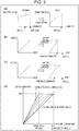
- Fig. 3 is a view illustrating processes performed by a first image processing unit 22 and a panel control unit 27, wherein Fig. 3(a) is a view illustrating the contents of gamma conversion by the first image processing unit 22.
- Fig. 3(a) shows the ST2084 signal which is input on the left.
- the horizontal axis denotes luminance
- the vertical axis denotes gradation values.
- the luminance of the ST2084 signal has values up to 10000 cd/m 2 .
- the Maximum Content Light Level (MAX CLL) on the horizontal axis shows the largest luminance value of a predetermined unit (e.g., one scene) of the contents.
- the first image processing unit 22 cuts the ST2084 signal shown on the left in Fig. 3(a) at a luminance of MAX CLL and assigns luminance values from 0 to MAX CLL to ⁇ 2.2 (on the right in Fig. 3(a) ), thereby performing the gamma conversion.
- using the part of the ST2084 signal corresponding to the luminance values from MAX CLL to 10000 cd/m 2 enables unnecessary loss of gradation to be prevented.
- MAX FALL Maximum Frame-average Light Level
- the first image processing unit 22 performs gradation performance conversion (gamma conversion) of converting, in accordance with the maximum luminance level (MAX CLL or MAX FALL) indicated by the HDR signal input to the first image processing unit 22, a gradation performance indicated by the HDR signal into a prescribed gradation performance (gamma 2.2) according to the display panel 10.
- gradation performance conversion gamma conversion
- the second image processing unit 23 performs processing of the SDR signal. Note that since the processing of the SDR signal can be performed by a known technique, the detailed description thereof is omitted.
- the image composition unit 24 consolidates a result of the process performed by the first image processing unit 22 and a result of the process performed by the second image processing unit 23 into a single video signal.
- the OSD generation unit 25 generates OSD data for OSD display and transmits the OSD data to the superimposed image generation unit 26.
- the superimposed image generation unit 26 superimposes the OSD data (a superimposition target image) transmitted from the OSD generation unit 25 over the video signal (input signal) received from the image composition unit 24.
- OSD data a superimposition target image
- the character is white with a gradation value of 255 based on the SDR.
- a character of the OSD which is white with a gradation value of 255 is superimposed based on the HDR, the character is expressed unnecessarily brightly.
- the superimposed image generation unit 26 includes a gain adjustment unit, and during HDR display, the superimposed image generation unit 26 uses, for example, MAX CLL of the video signal received from the image composition unit 24 to calculate gain and multiply the OSD gradation by the gain, thereby ensuring that the OSD (displaying the character) during HDR has the same luminance (gradation level) as that when displaying the character in SDR.
- Fig. 4 is a view illustrating a calculation method of gain during superimposing an OSD data, wherein FIG. 4(a) is a diagram of a superimposition circuit, and FIG. 4(b) is a view illustrating a graph for calculating the gain. As illustrated in Fig.
- the OSD data expressed by 1023 gradations is multiplied by the gain to obtain a resultant, and the resultant is superimposed on a signal obtained by the gamma conversion of the ST2084 signal (in Fig. 4(a) , conversion by referring to a Look Up Table (LUT) is shown) to obtain an output signal.
- LUT Look Up Table
- the gain by which the OSD data is multiplied is derived in accordance with the ratio of MAX CLL to Peak Luminance.
- Peak Luminance refers to the maximum display luminance of the display panel 10.
- the panel control unit 27 performs tone mapping of the video signal received from the superimposed image generation unit 26, thereby enabling the video signal to be displayed at an appropriate luminance by the display panel 10.
- the tone mapping determines assignment of luminance information included in the video signal to luminance which can be expressed by the display panel 10.
- the tone mapping may be performed by storing a plurality of patterns of tone maps in the storage unit 30 which will be described later and by causing a user to select an appropriate tone map, or the tone mapping may be performed by using a Look Up Table (LUT) or a formula (a prescribed computation).
- LUT Look Up Table
- the tone map shows a correspondence relationship between the gradation values indicated by the HDR signal and the gradation values displayable by the display panel 10.
- tone mapping is conversion of the luminance information with reference to a tone map (tone curve).
- tone map is a trajectory showing the relationship between the luminance information before the conversion and the luminance information after the conversion (a map with the horizontal axis representing the luminance information before the conversion and the vertical axis representing the luminance information after the conversion).
- the display panel 10 cannot express all the luminance values included in the video signal.
- the luminance of the video signal is expressed as is up to the maximum luminance that can be expressed by the display panel 10, and a portion of the luminance of the video signal higher than the maximum luminance that can be expressed by the display panel 10 is subjected to the tone mapping so that the portion can be displayed at the maximum luminance that can be expressed by the display panel 10.
- the gradation of a high-luminance part of the video signal is lost, but the luminance of the video signal can be expressed as accurately as possible.
- the tone mapping may be performed to prevent the gradation of the high-luminance part of the video signal from being lost.
- the luminance of the video signal is expressed as is (expressed linearly) up to a prescribed luminance (luminance threshold value), and the luminance higher than the prescribed luminance (in other words, above the luminance threshold value) is mapped to draw a smooth curve such that MAX CLL eventually coincides with the maximum luminance that can be expressed by the display panel 10.
- the prescribed luminance is determined based on at least a luminance of the video signal up to which the gradation is actually expressed.
- the gradation of the high-luminance part of the video signal is not lost, but the luminance of the video signal can be expressed as actually as possible.
- Fig. 3(d) shows a specific example of the tone mapping including the examples shown in Figs. 3(b) and 3(c) . Note that in this embodiment, the gradation is expressed in 1023 gradations (the gradation indicating MAX CLL is 1023).
- the graph indicated by "laying stress on luminance (+2)" corresponds to the tone curve for performing the tone mapping shown in FIG. 3(b) .
- one of the tone curves indicated by broken lines corresponds to the tone curve for performing the tone mapping shown in Fig. 3(c) .
- the tone curve shown in the graph shown by laying stress on gradation (-2) shown in Fig. 3(d) is an example of the tone mapping of a case where stress is laid on the gradation of the video signal. In this case, the gradation of the video signal is expressed, but the luminance of the video signal cannot be expressed accurately, resulting in video which is slightly dark (with low luminance).
- the panel control unit 27 is configured to perform gradation value conversion (tone mapping) of converting, in accordance with the maximum luminance level (MAX CLL or MAX FALL) indicated by the HDR signal and a maximum luminance displayable by the display panel 10, a gradation value (luminance) indicated by the HDR signal after the gradation performance conversion (gamma conversion) into a gradation value (luminance) displayable by the display panel 10.
- gradation value conversion tone mapping
- the storage unit 30 stores information and includes a nonvolatile device, such as flash memory or Read Only Memory (ROM), and a volatile device, such as Random Access Memory (RAM). Examples of contents stored in the nonvolatile device include various programs, various operation configuration values, and various types of data. Examples of contents stored in the volatile device include files for work and temporary files.
- the storage unit 30 includes a computation table 31.
- the storage unit 30 may store a plurality of patterns of tone maps as described above.
- the computation table 31 is a table used for the gamma conversion process executed by the first image processing unit 22 and the tone mapping computation executed by the panel control unit 27.
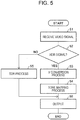
- Fig. 5 is a flow chart showing a flow of processes performed by the display device 1.
- the video selecting unit 21 determines whether or not the video signal received by the display device 1 includes an HDR signal (S2), and if the video signal includes the HDR signal (YES in S2), the video selecting unit 21 transmits the video signal to the first image processing unit 22.
- the first image processing unit 22 performs the gamma conversion process of the video signal (HDR signal) received by the display device 1 (S3).
- the video signal after the gamma conversion process is transmitted to the panel control unit 27, and a tone mapping process is executed by the panel control unit 27 (S4).
- the video signal after the tone mapping process is then output to the display panel 10 (S6).
- step S2 if it is determined in step S2 that the video signal received by the display device 1 does not include the HDR signal (i.e., includes an SDR signal) (NO in S2), the video selecting unit 21 transmits the video signal (SDR signal) received by the display device 1 to the second image processing unit 23. Then, the second image processing unit 23 performs processing of the SDR signal (S5). Thereafter, the video signal after the processing of the SDR signal is output to the display panel 10 (S6).
- the present embodiment describes a process method in a case of receiving two video signals which are a video signal (image signal) including an HDR signal and a video signal (image signal) including an SDR signal, that is, a case of two-screen display for displaying two video signals which are an HDR signal and an SDR signal. If the process by the panel control unit 27 can be performed only to the entirety of the screen in the case of the two-screen display for displaying the two video signals, which are the HDR signal and the SDR signal, the quality of video of the HDR signal or video of the SDR signal degrades. Thus, in the present embodiment, the HDR signal is converted into the SDR signal to perform a process based on the SDR signal on the entirety of the screen so as to prevent degradation in quality of the video.
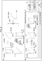
- Fig. 6 is a view illustrating processes for the two-screen display, wherein Fig. 6(a) is a view illustrating the contents of a process by the first image processing unit 22, and Fig. 6(b) is a view illustrating a process by the panel control unit 20.
- the first image processing unit 22 in a case of one screen for the HDR signal, the first image processing unit 22 only executes the gamma conversion process.
- the first image processing unit 22 performs simple tone mapping by the panel control unit 27 in addition to the gamma conversion process and consolidates the result of the gamma conversion and the result of the simple tone mapping to generate an output signal. That is, the result of the gamma conversion is not output as is, but an output obtained by reflecting the result of the simple tone mapping by the result of the gamma conversion is output. In the output signal shown in Fig.
- the tone curve indicated by a broken line shows a case where only the gamma conversion is performed
- the tone curve indicated by the solid line shows a case where the result of the simple tone mapping is consolidated with the result of the gamma conversion.
- the simple tone mapping does not mean that the maximum luminance that can be expressed by the display panel 10 is varied depending on video scenes indicated by the video signal, but the simple tone mapping means that the tone mapping is performed by a value configured in advance.
- the video signal which the first image processing unit 22 outputs is similar to the SDR signal.
- the panel control unit 27 processes, as SDR signals, the video signals which are acquired via the image composition unit 24 and the superimposed image generation unit 26 and which are output from the first image processing unit 22 and the second image processing unit 23, and the panel control unit 27 outputs the video signals to the display panel 10.
- both the video signal including the HDR signal and the video signal including the SDR signal can be displayed in two screens. Note that it can be said that in the present embodiment, video signals are displayed by being unified into the SDR signal.
- the present embodiment describes a process method in a case of receiving two video signals which are a video signal including an HDR signal and a video signal including an SDR signal, that is, a case of two-screen display for displaying two video signals which are an HDR signal and an SDR signal.
- the configuration in which video signals are displayed by being unified into the SDR signal is described, but in the present embodiment, the video signals are displayed by being unified into the HDR signal.
- a panel control unit 27 performs inverse tone mapping on an SDR signal received from a second image processing unit 23 such that the SDR signal becomes a video signal similar to the HDR signal. Then, the panel control unit 27 outputs to the display panel 10 a video signal including an HDR signal received from a first image processing unit 22 and the video signal which includes a signal corresponding to the HDR signal and which is obtained by converting the video signal including the SDR signal received from a second image processing unit 23.
- both the video signal including the HDR signal and the video signal including the SDR signal can be displayed in two screens.
- the inverse tone mapping (inverse conversion of the gradation value conversion) means converting the tone curve of the SDR signal into the tone curve of the HDR signal.
- the present embodiment includes a user interface (UI) with which a user selects a degree to which the luminance indicated by an HDR signal is reflected by the display.
- UI user interface
- Including the user interface enables a video signal including the HDR signal to be displayed at luminance desired by the user.
- Fig. 7 is a view illustrating an example of the user interface.
- a video configuration screen has an input area 801 of the HDR gamma configuration to receive an HDR gamma configuration.
- the HDR gamma configuration is received by five stages from "-2" to "+2".
- Fig. 7 shows an example in which the HDR gamma configuration is received by a slide bar, but the embodiment is not limited to the slide bar, and the HDR gamma configuration may be received via, for example, a radio button or the like.
- the user interface may be configured to display the video signal only when the video signal input to the display device 1 is the HDR signal. With this configuration, the user interface can be displayed only when needed. Moreover, when a signal other than the HDR signal is input, the user interface is displayed by being hatched.
- configuration items of a menu may be grayed out, or a mark denoting that operation is forbidden (e.g., a sign of parking prohibition, a no-entry sign) is displayed, so that a user can understands at a glance that the operation is not possible.
- FIG. 8 and 9 is a view illustrating an HDR gamma configuration and tone curves corresponding to the HDR gamma configuration, wherein Figs. 8(a) and 9(a) are views illustrating the tone curves, and Figs. 8(b) and 9(b) are views illustrating the relationship between the configuration values of the HDR gamma configuration and parameter values in a conversion formula.
- Tone mapping executed by the panel control unit 27 may be performed based on a graph itself, by referring to a conversion table, or in accordance with a conversion formula.
- Fig. 8(a) shows an example of tone curves when conversion is performed in accordance with the formula. Note that the value of ⁇ varies depending on an HDR gamma configuration value received with the user interface described in the fourth embodiment. Fig. 8(b) shows the relationship between the HDR gamma configuration value and the value of ⁇ .
- Example 1-1 and Example 1-2 are shown.
- Example 1-1 when the HDR gamma configuration value is “-2", ⁇ is “0”, when the HDR gamma configuration value is “-1”, ⁇ is "0.25", ....
- Example 1-2 when the HDR gamma configuration value is “-2”, ⁇ is “0”, when the HDR gamma configuration value is "-12”, ⁇ is "0.3”, ....
- Example 1-1 when the HDR gamma configuration value is “-2”, ⁇ is "0”, when the HDR gamma configuration value is "-12”, ⁇ is "0.3”, ....
- FIG. 9(a) shows an example of tone curves when conversion is performed in accordance with the formula. Note that the value of ⁇ varies depending on the HDR gamma configuration value received with the user interface described in the fourth embodiment. Fig. 9(b) shows the relationship between the HDR gamma configuration value and the value of ⁇ .
- Example 2-1 and Example 2-2 are shown.
- Example 2-1 when the HDR gamma configuration value is “-2", ⁇ is “0", when the HDR gamma configuration value is “-1”, ⁇ is "0.25", ....
- Example 2-2 when the HDR gamma configuration value is “-2”, ⁇ is “0”, when the HDR gamma configuration value is "-12”, ⁇ is "0.3”, .... The same follows hereafter.
- Control blocks (in particular, the image control unit 20 (the video selecting unit 21, the first image processing unit 22, the second image processing unit 23, the image composition unit 24, the OSD generation unit 25, the superimposed image generation unit 26, and the panel control unit 27) of the display device 1 may be realized by logic circuits (hardware) formed in an integrated circuit (IC chip) or by software by using a Central Processing Unit (CPU).
- logic circuits hardware formed in an integrated circuit (IC chip) or by software by using a Central Processing Unit (CPU).
- the display device 1 includes, for example, a CPU which executes a command of a program which is software for realizing various functions, Read Only Memory (ROM) or a storage device (which is referred to as a "recording medium") in which the program and various types of data are stored in a manner readable by a computer (or the CPU), and Random Access Memory (RAM) into which the program is to be loaded.
- the computer or the CPU
- the recording medium a non-transitory tangible medium, for example, a tape, disk, card, semiconductor memory, or programmable logic circuit can be used.
- the program may be supplied to the computer via any transmission medium (for example, a communication network or a broadcast wave) which can transmit the program.
- the program may also be realized in a form of a data signal embodied by electronical transmission and embedded in a carrier wave.
- a display device (1) is a display device configured to display an image indicated by an HDR signal and an image indicated by an SDR signal, the display device including: a display panel (10); a panel control unit (27) configured to control the display panel; a first image processing unit (22), wherein the first image processing unit is configured to perform gradation performance conversion of converting, in accordance with a maximum luminance level indicated by an HDR signal input to the first image processing unit, a gradation performance indicated by the HDR signal into a prescribed gradation performance according to the display panel, and the panel control unit is configured to perform gradation value conversion of converting, in accordance with the maximum luminance level indicated by the HDR signal and a maximum luminance displayable by the display panel, a gradation value indicated by the HDR signal after the gradation performance conversion into a gradation value displayable by the display panel.
- the gradation performance conversion into a prescribed gradation performance according to the display panel is performed in accordance with the maximum luminance level indicated by the HDR signal, and the gradation value conversion is performed in accordance with the maximum luminance level indicated by the HDR signal and the maximum luminance displayable by the display panel.
- This enables the HDR signal to have a gradation value compatible with a display panel, and even when the maximum luminance level indicated by the HDR signal is higher than the luminance displayable by the display panel, the display panel is enabled to display an image indicated by the HDR signal at an appropriate gradation value.
- a display device may include a superimposed image generation unit (26) including a gain adjustment unit configured to change a gradation level of a superimposition target image depending on whether an input signal is the HDR signal or the SDR signal, wherein the superimposed image generation unit may be configured to superimpose the superimposition target image on an image indicated by the HDR signal after the gradation performance conversion by the first image processing unit.
- a superimposed image generation unit (26) including a gain adjustment unit configured to change a gradation level of a superimposition target image depending on whether an input signal is the HDR signal or the SDR signal, wherein the superimposed image generation unit may be configured to superimpose the superimposition target image on an image indicated by the HDR signal after the gradation performance conversion by the first image processing unit.
- This configuration enables the gradation level of the superimposition target image to be changed depending on whether the input signal is the HDR signal or the SDR signal.
- the superimposition target image thus results in an image including blown-out highlights and/or to prevent that the gradation value of the superimposition target image is too low with respect to the input signal, and the gradation of the superimposition target image is thus lost.
- Examples of the superimposition target image include an On Screen Display (OSD) image.
- OSD On Screen Display
- the OSD image displayed at a luminance corresponding to the HDR signal is too bright and is likely to be an image including blown-out highlights.
- the gradation value of the OSD image is multiplied by gain to lower the luminance, and thus, even in the case of the OSD image, it is possible to appropriately display the OSD image.
- a display device referring to the first or second aspect may include: an image composition unit (24); and a second image processing unit (23) which is different from the first image processing unit, wherein the image composition unit may be configured to combine image signals output from the first image processing unit and the second image processing unit to obtain a combined image signal and output the combined image signal to the panel control unit, and the second image processing unit may be configured to perform inverse conversion of the gradation value conversion on the SDR signal which is input.
- the display quality of one of the HDR signal and the SDR signal may degrade.
- performing the inverse conversion of the gradation value conversion converts the SDR signal which is input into a signal corresponding to the HDR signal.
- the SDR signal input to the display device is converted into a signal corresponding to the HDR signal, and therefore, the SDR signal can be processed as the HDR signal.
- the display panel can be caused to display the HDR signal and the SDR signal at an appropriate gradation value.
- the panel control unit may have a prescribed luminance threshold value lower than a maximum luminance displayable by the display panel, and a luminance lower than or equal to the luminance threshold value may be converted into a luminance denoted by a gradation value indicated by the HDR signal.
- the luminance lower than or equal to the prescribed luminance threshold value is converted into a luminance indicated by the gradation value, and therefore, for the luminance lower than or equal to the prescribed luminance threshold value, the gradation indicated by the HDR signal can be accurately expressed.
- the first image processing unit may be configured to execute the gradation performance conversion by performing a prescribed computation or by referring to a look-up table.
- This configuration enables the gradation performance conversion to be executed by performing the prescribed computation or by referring to the look-up table.
- a display device referring to any one of the first to fifth aspects may include a storage unit configured to store a plurality of patterns of tone maps denoting a correspondence relationship between the gradation value indicated by the HDR signal and the gradation value displayable by the display panel, wherein the panel control unit may be configured to perform the gradation value conversion with reference to a tone map selected by a user.
- the gradation value conversion is executed with reference to the tone map selected by a user, and thus, gradation value conversion desired by the user can be executed.
- the plurality of tone maps include a tone map showing gradation value conversion with stress laid on the gradation and a tone map showing gradation value conversion with stress laid on the luminance
- the gradation value conversion with stress laid on the gradation or the gradation value conversion with stress laid on the luminance can be performed based on selection by a user.
- a display device referring to the sixth aspect may include a display control unit configured to display a user interface with which a user selects the tone map, wherein the user interface may be configured to receive a selection by a user via a slide bar or a radio button, and the display control unit may be configured to display the user interface when a signal to be displayed is the HDR signal or to change a display form of the user interface depending on whether or not the signal to be displayed is the HDR signal.
- the display control unit displays the user interface when a signal to be displayed is the HDR signal or changes the display form of the user interface depending on whether or not the signal to be displayed is the HDR signal.
- a signal to be displayed in other words, an input signal
- the gradation value conversion is not required. Therefore, according to this configuration, it is possible to display the user interface or to change the user interface to be displayed in a case of the HDR signal which requires the gradation value conversion.
- this configuration can receive a selection by a user via a slide bar or a radio button, and therefore, intuitive sense of operation can be provided to the user.
- the tone map may show, in the display panel, a luminance denoted by a gradation value indicated by the HDR signal, a luminance denoted by a gradation value indicated by the HDR signal up to a luminance displayable by the display panel, or a luminance denoted by the gradation value indicated by the HDR signal up to a prescribed threshold value and a luminance denoted by the gradation value appropriately above the threshold value.
- using the tone map enables the display panel to accurately display the gradation indicated by the HDR signal, to accurately display the luminance corresponding to the gradation value indicated by the HDR signal up to a luminance displayable by the display panel, or to accurately display the luminance corresponding to the gradation indicated by the HDR signal up to the prescribed threshold value, and to appropriately display the gradation over the threshold value.
- a display device is a display device a display device configured to display an image indicated by an HDR signal and an image indicated by an SDR signal, the display device including: a display panel; a panel control unit configured to control the display panel; a plurality of image processing units; and an image composition unit, wherein the image composition unit is configured to combine image signals output from the plurality of image processing units to obtain a combined image signal and output the combined image signal to the panel control unit, an image processing unit of the plurality of image processing units which receives the HDR signal converts the gradation performance indicated by the HDR signal into a prescribed gradation performance according to the display panel and converts the prescribed gradation performance into an SDR signal.
- the display panel can be caused to display the HDR signal and the SDR signal at an appropriate gradation value.
- a television set according to a tenth aspect of the present invention includes the display device.
- a method for controlling a display device is a method for controlling a display device configured to display an image indicated by an HDR signal and an image indicated by an SDR signal, the display device including: a display panel; a panel control unit configured to control the display panel; and a first image processing unit, wherein performing gradation performance conversion by using the first image processing unit to convert, in accordance with a maximum luminance level indicated by an HDR signal input to the first image processing unit, a gradation performance indicated by the HDR signal into a prescribed gradation performance according to the display panel, and performing gradation value conversion by using the panel control unit to convert, in accordance with the maximum luminance level indicated by the HDR signal and a maximum luminance displayable by the display panel, a gradation value indicated by the HDR signal after the gradation performance conversion into a gradation value displayable by the display panel.
- This method provides an advantage similar to the advantages of the first aspect described above.
- the display device may be realized by a computer.
- the scope of the present invention includes a control program of the display device which causes a computer to operate as each component (software elements) included in the display device to realize the display device by the computer, and a computer-readable recording medium which stores the control program.
Landscapes
- Engineering & Computer Science (AREA)
- Multimedia (AREA)
- Signal Processing (AREA)
- Physics & Mathematics (AREA)
- Computer Hardware Design (AREA)
- General Physics & Mathematics (AREA)
- Theoretical Computer Science (AREA)
- Picture Signal Circuits (AREA)
- Controls And Circuits For Display Device (AREA)
- Image Processing (AREA)
- Transforming Electric Information Into Light Information (AREA)
Abstract
Description
- The present invention relates to a display device compatible with a High Dynamic Range (HDR) technique.
- A High Dynamic Range (HDR) technique is a known function for increasing display image quality. An HDR signal can have luminance information of about 10000 nits (cd/m2). Therefore, using an HDR technique enables an increase in luminance and contrast, which can enhance the impact of video. For example, Blu-ray (registered trademark) Disc adopts the HDR technique.
- The luminance displayable by a display device has, however, an upper limit. Even when a signal (HDR signal) generated by the HDR technique is input, the luminance indicated by the HDR signal may be impossible to display.
-
PTL 1 andPTL 2 each describe a technique for adjusting the luminance of a display device.PTL 1 discloses a technique for adjusting luminance by calculating a typical gradation value of each dimming unit domain in accordance with input image data, generating, with reference to a target gamma curve, a target luminance value corresponding to the typical gradation value which is calculated, and calculating an emission luminance value in each issuance unit block in accordance with the target luminance value. - Moreover,
PTL 2 discloses a technique for adjusting the luminance of an OSD image by determining an OSD signal to be output by using gradation data associated with the feature of a video signal to be displayed in a display area of the OSD image. -
- PTL 1: Japanese Unexamined Patent Application Publication No.
2009-175740 (Publication Date: August 6, 2009 - PTL 2: Japanese Unexamined Patent Application Publication No.
2013-182119 (Publication Date: September 12, 2013 -
PTL 1 andPTL 2 fail, however, to propose a solution for a case where luminance displayable by the display device is not compatible with luminance indicated by an HDR signal received by the display device. Thus, in bothPTL 1 andPTL 2, when the luminance displayable by the display device is lower than the luminance indicated by the HDR signal received by the display device, the display device cannot display at an appropriate luminance video indicated by the HDR signal input to the display device. - In view of the above problems, it is an object of the present invention to realize a display device capable of appropriately displaying luminance indicated by an HDR signal input to the display device.
- To solve the problem, a display device according to the present invention is a display device configured to display an image indicated by an HDR signal and an image indicated by an SDR signal, the display device including: a display panel; a panel control unit configured to control the display panel; and a first image processing unit, wherein the first image processing unit is configured to perform gradation performance conversion of converting, in accordance with a maximum luminance level indicated by an HDR signal input to the first image processing unit, a gradation performance indicated by the HDR signal into a prescribed gradation performance according to the display panel, and the panel control unit is configured to perform gradation value conversion of converting, in accordance with the maximum luminance level indicated by the HDR signal and a maximum luminance displayable by the display panel, a gradation value indicated by the HDR signal after the gradation performance conversion into a gradation value displayable by the display panel.
- To solve the problem, a display device according to the present invention is a display device configured to display an image indicated by an HDR signal and an image indicated by an SDR signal, the display device including a display panel; a panel control unit configured to control the display panel; a plurality of image processing units; and an image composition unit, wherein the image composition unit is configured to combine image signals output from the plurality of image processing units to obtain a combined image signal and output the combined image signal to the panel control unit, and an image processing unit of the plurality of image processing units which receives the HDR signal converts the gradation performance indicated by the HDR signal into a prescribed gradation performance according to the display panel and converts the prescribed gradation performance into an SDR signal.
- To solve the problem, a method for controlling a display device according to the present invention is a method for controlling a display device configured to display an image indicated by an HDR signal and an image indicated by an SDR signal, the display device including a display panel; a panel control unit configured to control the display panel; and a first image processing unit, the method including: performing gradation performance conversion by using the first image processing unit to convert, in accordance with a maximum luminance level indicated by an HDR signal input to the first image processing unit, a gradation performance indicated by the HDR signal into a prescribed gradation performance according to the display panel, and performing gradation value conversion by using the panel control unit to convert, in accordance with the maximum luminance level indicated by the HDR signal and a maximum luminance displayable by the display panel, a gradation value indicated by the HDR signal after the gradation performance conversion into a gradation value displayable by the display panel.
- The present invention enables an HDR signal to have a gradation value compatible with a display panel, and provides the advantage that even when the maximum luminance level indicated by the HDR signal is higher than the luminance displayable by the display panel, the display panel is enabled to display an image indicated by the HDR signal at an appropriate gradation value.
-
- [
Fig. 1] Fig. 1 is a block diagram illustrating main components of a display device according to an embodiment of the present invention. - [
Fig. 2] Fig. 2 is a view illustrating the exterior of the display device. - [
Fig. 3] Fig. 3 is a view illustrating processes performed by a firstimage processing unit 22 and apanel control unit 27 of the display device, whereinFig. 3(a) is a view illustrating the contents of gamma conversion by the firstimage processing unit 22, andFigs. 3(b) to 3(d) are views illustrating specific examples of tone mapping executed by thepanel control unit 27. - [
Fig. 4] Fig. 4 is a view illustrating a calculation method of gain during superimposing an OSD data, whereinFig. 4(a) is a diagram of a superimposition circuit, andFig. 4(b) is a view illustrating a graph for calculating the gain. - [
Fig. 5] Fig. 5 is a flowchart illustrating a flow of processes performed by the display device. - [
Fig. 6] Fig. 6 is a view illustrating processes for two-screen display, whereinFig. 6(a) is a view illustrating the contents of a process by the firstimage processing unit 22, andFig. 6(b) is a view illustrating a process by thepanel control unit 20. - [
Fig. 7] Fig. 7 is a view illustrating an example of a user interface. - [
Fig. 8] Fig. 8 is a view illustrating an HDR gamma configuration and tone curves corresponding to the HDR gamma configuration, whereinFig. 8(a) is a view illustrating the tone curves, andFig. 8(b) is a view illustrating the relationship between the configuration value of the HDR gamma configuration and a parameter value in a conversion formula. - [
Fig. 9] Fig. 9 is a view illustrating an HDR gamma configuration and tone curves corresponding to the HDR gamma configuration, whereinFig. 9(a) is a view illustrating the tone curves, andFig. 9(b) is a view illustrating the relationship between the configuration value of the HDR gamma configuration and a parameter value in a conversion formula. Description of Embodiments - With reference to
Figs. 1 to 6 , adisplay device 1 according to an embodiment of the present invention will be described in detail below. When thedisplay device 1 according to the present embodiment receives a High Dynamic Range (HDR) signal, thedisplay device 1 appropriately controls luminance to be displayed, thereby displaying video without degrading the luminance indicated by the HDR signal. - A current HDR signal adopts an Electro-Optical Transfer Function (EOTF) different from γ2.2 of a conventional SDR signal. Examples of the EOTF include an EOTF defined in accordance with SMPTE-ST2084. Note that in the following description, the EOTF defined in accordance with the SMPTE-ST2084 of the HDR signal is referred to as a ST2084 signal.
- Since the gamma curve of the ST2084 signal has a shape different from that of γ2.2, the ST2084 signal cannot be appropriately displayed by a display device compatible with the conventional γ2.2 (a display device compatible with the SDR signal).
- Moreover, causing a conventional display device compatible with the SDR signal to be compatible with not only the SDR signal but also the ST2084 signal involves various problems, for example, addition of an adjustment step.
- Thus, in the present embodiment, the ST2084 signal is converted into γ2.2 so that the ST2084 signal can be displayed without adding an adjustment step even when a display device is compatible with the SDR signal.
- Moreover, the ST2084 signal includes luminance information up to 10000 cd/m2, but no display device which enables such a high luminance to be displayed is currently available. Thus, the present embodiment performs mapping (tone mapping) of the HDR signal within a luminance range displayable by the display device to enable the display device to appropriately display the luminance (gradation) indicated by the ST2084 signal.
- Note that the present embodiment describes but is not limited to an example in which the HDR signal is the ST2084 signal (adopts the EOTF defined in accordance with the SMPTE-ST2084). Any HDR signal may be used, and the standard with which the HDR signal is compatible is not limited.
- First, with reference to
Fig. 2 , the exterior of thedisplay device 1 will be described.Fig. 2 is a view illustrating the exterior of thedisplay device 1. As illustrated inFig. 2 , thedisplay device 1 is a so-called television set configured to display, on adisplay panel 10, television broadcast indicated by a received Tuner signal 12 (a signal received by a tuner). Moreover, thedisplay device 1 may receive a High-Definition Multimedia Interface (HDMI) (registered trademark)signal 11 based on the HDMI standard to display video or receive a Composite Video, Blanking, and Sync (CVBS)signal 13 to display video. - Note that in the present embodiment, a television set is described as an example of the
display device 1, but the present invention is not limited to this example, and any display device may be used as long as the display device is configured to display video. - Next, with reference to
Fig. 1 , details of thedisplay device 1 will be described.Fig. 1 is a block diagram illustrating main components of thedisplay device 1. As illustrated inFig. 1 , thedisplay device 1 according to the present embodiment includes thedisplay panel 10, an image control unit (display control unit) 20, and astorage unit 30. - The
display panel 10 is a display device that displays video and the like, and any display device may be used as long as the display device can display information. Specific examples of the display device include a liquid crystal display, an organic Electro Luminescence (EL) display, and a plasma display. - The
image control unit 20 adjusts the luminance to be displayed by thedisplay panel 10 depending on whether or not a received video signal is the HDR signal, and theimage control unit 20 executes various processes of thedisplay device 1. As illustrated inFig. 1 , theimage control unit 20 includes a videodata acquisition unit 29, avideo selecting unit 21, a firstimage processing unit 22, a secondimage processing unit 23, animage composition unit 24, an On Screen Display (OSD)generation unit 25, a superimposedimage generation unit 26, and apanel control unit 27. - The video
data acquisition unit 29 receives at least one of anHDMI signal 11, theTuner signal 12, and aCVBS signal 13 and transmits the signal to thevideo selecting unit 21. Note that when it is not necessary to distinguish theHDMI signal 11, theTuner signal 12, and theCVBS signal 13 from one another, these signals are referred to as video signals. The video signal which the videodata acquisition unit 29 receives includes data indicating whether or not the video signal is an HDR signal and data indicating "MAX CLL" and "MAX FALL" in addition to video data which will be described later. - The
video selecting unit 21 determines whether or not theHDMI signal 11, theTuner signal 12, and theCVBS signal 13 received from the videodata acquisition unit 29 are HDR signals or Standard Dynamic Range (SDR) signals to obtain a determination result, and based on the determination result, thevideo selecting unit 21 transmits the video signals, which thevideo selecting unit 21 receives, to the firstimage processing unit 22 or the secondimage processing unit 23. For example, when the video signals which thevideo selecting unit 21 receives are video signals including the HDR signals, thevideo selecting unit 21 transmits the video signals to the firstimage processing unit 22, and when the video signals which thevideo selecting unit 21 receives are video signals including the SDR signals, thevideo selecting unit 21 transmits the video signals to the secondimage processing unit 23. - Determination of whether or not the video signals are the HDR signals can be made with reference to, for example, the EOTF of an INFO FRAME of the HDMI signal.
- Moreover, in a method conforming to the HEVC standard, the determination can be made with reference to transfer_characteristics of a VUI parameter included in a sequence parameter set.
- Moreover, when MMT is used as a multiplexing method of advanced BS digital broadcasting, the determination can be made with reference to video_transfer_characteristics included in a Video_Component_Descriptor included in an MMT Package Table (MPT) stored in a PA message of an MMT-SI message. Alternatively, the determination can be made with reference to video_transfer_characteristics included in a Video_Component_Descriptor included in an MH-Evnet Information Table (MH-EIT) [schedule actual basic] stored in an M2 section message of the MMT-SI message.
- Moreover, in a case of an MPEG-2TS method, the determination can be made with reference to
transfer_characteristics of a video decode control descriptor. - As described above, in the present embodiment, the video
data acquisition unit 29 acquires video data including HDR signal determination data, which is data for determining whether or not the video signal is the HDR signal. Thevideo selecting unit 21 includes an HDR signal determination data acquisition unit configured to acquire the HDR signal determination data from the video data which the videodata acquisition unit 29 acquires. With reference to the HDR signal determination data acquired by the HDR signal determination data acquisition unit, thevideo selecting unit 21 determines whether or not the video signal is the HDR signal. - Note that the HDR signal determination data is, for example, the EOTF of an INFO FRAME of the HDMI signal, the transfer_characteristics of the VUI parameter included in the sequence parameter set, the video_transfer_characteristics included in the Video_Component_Descriptor, which is one descriptor of the time direction hierarchical coding HEVC, or the transfer_characteristics of the video decode control descriptor, which is described above.
- The first
image processing unit 22 converts (performs gamma conversion of) a signal (ST2084 signal) of SMPTE Standard ST2084 conforming to the standard of HDR into a signal of γ2.2 (gamma correction with a gamma value of 2.2). The gamma conversion will be described in detail with reference toFig. 3(a). Fig. 3 is a view illustrating processes performed by a firstimage processing unit 22 and apanel control unit 27, whereinFig. 3(a) is a view illustrating the contents of gamma conversion by the firstimage processing unit 22.Fig. 3(a) shows the ST2084 signal which is input on the left. Here, the horizontal axis denotes luminance, and the vertical axis denotes gradation values. As illustrated inFig. 3(a) , the luminance of the ST2084 signal has values up to 10000 cd/m2. Moreover, the Maximum Content Light Level (MAX CLL) on the horizontal axis shows the largest luminance value of a predetermined unit (e.g., one scene) of the contents. The firstimage processing unit 22 cuts the ST2084 signal shown on the left inFig. 3(a) at a luminance of MAX CLL and assigns luminance values from 0 to MAX CLL to γ2.2 (on the right inFig. 3(a) ), thereby performing the gamma conversion. Thus, using the part of the ST2084 signal corresponding to the luminance values from MAX CLL to 10000 cd/m2 enables unnecessary loss of gradation to be prevented. - This embodiment describes that the gamma conversion is performed with reference to MAX CLL, but instead of MAX CLL, Maximum Frame-average Light Level (MAX FALL) may be used to perform the gamma conversion. Moreover, MAX CLL and MAX FALL are stored in metadata included in, for example, an INFO FRAME of the HDMI signal.
- As described above, the first
image processing unit 22 performs gradation performance conversion (gamma conversion) of converting, in accordance with the maximum luminance level (MAX CLL or MAX FALL) indicated by the HDR signal input to the firstimage processing unit 22, a gradation performance indicated by the HDR signal into a prescribed gradation performance (gamma 2.2) according to thedisplay panel 10. - The second
image processing unit 23 performs processing of the SDR signal. Note that since the processing of the SDR signal can be performed by a known technique, the detailed description thereof is omitted. - When both the first
image processing unit 22 and the secondimage processing unit 23 perform the processes, theimage composition unit 24 consolidates a result of the process performed by the firstimage processing unit 22 and a result of the process performed by the secondimage processing unit 23 into a single video signal. - The
OSD generation unit 25 generates OSD data for OSD display and transmits the OSD data to the superimposedimage generation unit 26. - The superimposed
image generation unit 26 superimposes the OSD data (a superimposition target image) transmitted from theOSD generation unit 25 over the video signal (input signal) received from theimage composition unit 24. When a character of the OSD is expressed as a white character, the character is white with a gradation value of 255 based on the SDR. In contrast, when a character of the OSD which is white with a gradation value of 255, as in the case of the SDR, is superimposed based on the HDR, the character is expressed unnecessarily brightly. Thus, the superimposedimage generation unit 26 includes a gain adjustment unit, and during HDR display, the superimposedimage generation unit 26 uses, for example, MAX CLL of the video signal received from theimage composition unit 24 to calculate gain and multiply the OSD gradation by the gain, thereby ensuring that the OSD (displaying the character) during HDR has the same luminance (gradation level) as that when displaying the character in SDR. A more specific description will be given with reference toFigs. 4 and5 .Fig. 4 is a view illustrating a calculation method of gain during superimposing an OSD data, whereinFIG. 4(a) is a diagram of a superimposition circuit, andFIG. 4(b) is a view illustrating a graph for calculating the gain. As illustrated inFig. 4(a) , the OSD data expressed by 1023 gradations is multiplied by the gain to obtain a resultant, and the resultant is superimposed on a signal obtained by the gamma conversion of the ST2084 signal (inFig. 4(a) , conversion by referring to a Look Up Table (LUT) is shown) to obtain an output signal. - The gain by which the OSD data is multiplied is derived in accordance with the ratio of MAX CLL to Peak Luminance. In this embodiment, Peak Luminance refers to the maximum display luminance of the
display panel 10. An example of a deriving method will be described with reference toFig. 4(b) . InFig. 4(b) , gain (OSD Gain) is shown on the vertical axis, and the ratio of MAX CLL to Peak Luminance (MAX CLL/Peak Luminance) is shown on the horizontal axis. - As illustrated in
Fig. 4(b) , the gain (OSD Gain) is determined as follows: when (MAXCLL/PEAK Luminance) ≤ x0, OSD Gain = y1, when x0 < (MAXCLL/PEAK Luminance) ≤ x1, OSD Gain = A × (MAXCLL/PEAK Luminance) + B, and when x1 < (MAXCLL/PEAK Luminance), OSD Gain = y0. - The
panel control unit 27 performs tone mapping of the video signal received from the superimposedimage generation unit 26, thereby enabling the video signal to be displayed at an appropriate luminance by thedisplay panel 10. The tone mapping determines assignment of luminance information included in the video signal to luminance which can be expressed by thedisplay panel 10. The tone mapping may be performed by storing a plurality of patterns of tone maps in thestorage unit 30 which will be described later and by causing a user to select an appropriate tone map, or the tone mapping may be performed by using a Look Up Table (LUT) or a formula (a prescribed computation). The tone map shows a correspondence relationship between the gradation values indicated by the HDR signal and the gradation values displayable by thedisplay panel 10. - That is, tone mapping is conversion of the luminance information with reference to a tone map (tone curve). The tone map (tone curve) is a trajectory showing the relationship between the luminance information before the conversion and the luminance information after the conversion (a map with the horizontal axis representing the luminance information before the conversion and the vertical axis representing the luminance information after the conversion).
- With reference to
Figs. 3(b), 3(c), and 3(d) , a specific example of the tone mapping performed by thepanel control unit 27 will be described. - When the value of MAX CLL is larger than the maximum luminance that can be expressed by the
display panel 10, thedisplay panel 10 cannot express all the luminance values included in the video signal. Thus, in the example shown inFig. 3(b) , the luminance of the video signal is expressed as is up to the maximum luminance that can be expressed by thedisplay panel 10, and a portion of the luminance of the video signal higher than the maximum luminance that can be expressed by thedisplay panel 10 is subjected to the tone mapping so that the portion can be displayed at the maximum luminance that can be expressed by thedisplay panel 10. Thus, the gradation of a high-luminance part of the video signal is lost, but the luminance of the video signal can be expressed as accurately as possible. - Moreover, the tone mapping may be performed to prevent the gradation of the high-luminance part of the video signal from being lost. In the example shown in
Fig. 3(c) , the luminance of the video signal is expressed as is (expressed linearly) up to a prescribed luminance (luminance threshold value), and the luminance higher than the prescribed luminance (in other words, above the luminance threshold value) is mapped to draw a smooth curve such that MAX CLL eventually coincides with the maximum luminance that can be expressed by thedisplay panel 10. Note that the prescribed luminance is determined based on at least a luminance of the video signal up to which the gradation is actually expressed. Thus, the gradation of the high-luminance part of the video signal is not lost, but the luminance of the video signal can be expressed as actually as possible. -
Fig. 3(d) shows a specific example of the tone mapping including the examples shown inFigs. 3(b) and 3(c) . Note that in this embodiment, the gradation is expressed in 1023 gradations (the gradation indicating MAX CLL is 1023). - When the luminance corresponding to the gradation of 1400 cd/m2 shown in
Fig. 3(d) corresponds to the maximum luminance that can be expressed by thedisplay panel 10, the graph indicated by "laying stress on luminance (+2)" corresponds to the tone curve for performing the tone mapping shown inFIG. 3(b) . Moreover, one of the tone curves indicated by broken lines corresponds to the tone curve for performing the tone mapping shown inFig. 3(c) . The tone curve shown in the graph shown by laying stress on gradation (-2) shown inFig. 3(d) is an example of the tone mapping of a case where stress is laid on the gradation of the video signal. In this case, the gradation of the video signal is expressed, but the luminance of the video signal cannot be expressed accurately, resulting in video which is slightly dark (with low luminance). - As described above, the
panel control unit 27 is configured to perform gradation value conversion (tone mapping) of converting, in accordance with the maximum luminance level (MAX CLL or MAX FALL) indicated by the HDR signal and a maximum luminance displayable by thedisplay panel 10, a gradation value (luminance) indicated by the HDR signal after the gradation performance conversion (gamma conversion) into a gradation value (luminance) displayable by thedisplay panel 10. - The
storage unit 30 stores information and includes a nonvolatile device, such as flash memory or Read Only Memory (ROM), and a volatile device, such as Random Access Memory (RAM). Examples of contents stored in the nonvolatile device include various programs, various operation configuration values, and various types of data. Examples of contents stored in the volatile device include files for work and temporary files. In the present embodiment, thestorage unit 30 includes a computation table 31. - Moreover, the
storage unit 30 may store a plurality of patterns of tone maps as described above. - The computation table 31 is a table used for the gamma conversion process executed by the first
image processing unit 22 and the tone mapping computation executed by thepanel control unit 27. - Next, with reference to
Fig. 5 , a flow of processes performed by thedisplay device 1 will be described.Fig. 5 is a flow chart showing a flow of processes performed by thedisplay device 1. As illustrated inFig. 5 , when thedisplay device 1 receives a video signal (S1), thevideo selecting unit 21 determines whether or not the video signal received by thedisplay device 1 includes an HDR signal (S2), and if the video signal includes the HDR signal (YES in S2), thevideo selecting unit 21 transmits the video signal to the firstimage processing unit 22. Then, the firstimage processing unit 22 performs the gamma conversion process of the video signal (HDR signal) received by the display device 1 (S3). Thereafter, the video signal after the gamma conversion process is transmitted to thepanel control unit 27, and a tone mapping process is executed by the panel control unit 27 (S4). The video signal after the tone mapping process is then output to the display panel 10 (S6). - On the other hand, if it is determined in step S2 that the video signal received by the
display device 1 does not include the HDR signal (i.e., includes an SDR signal) (NO in S2), thevideo selecting unit 21 transmits the video signal (SDR signal) received by thedisplay device 1 to the secondimage processing unit 23. Then, the secondimage processing unit 23 performs processing of the SDR signal (S5). Thereafter, the video signal after the processing of the SDR signal is output to the display panel 10 (S6). - The flow of the processes performed by the
display device 1 is as described above. - Next, another embodiment of the present invention will be described below with reference to
Fig. 6 . Note that for the sake of description, members having the same functions as those described in the embodiment described above are denoted by the same reference numbers, and the description thereof will be omitted. - The present embodiment describes a process method in a case of receiving two video signals which are a video signal (image signal) including an HDR signal and a video signal (image signal) including an SDR signal, that is, a case of two-screen display for displaying two video signals which are an HDR signal and an SDR signal. If the process by the
panel control unit 27 can be performed only to the entirety of the screen in the case of the two-screen display for displaying the two video signals, which are the HDR signal and the SDR signal, the quality of video of the HDR signal or video of the SDR signal degrades. Thus, in the present embodiment, the HDR signal is converted into the SDR signal to perform a process based on the SDR signal on the entirety of the screen so as to prevent degradation in quality of the video. -
Fig. 6 is a view illustrating processes for the two-screen display, whereinFig. 6(a) is a view illustrating the contents of a process by the firstimage processing unit 22, andFig. 6(b) is a view illustrating a process by thepanel control unit 20. - As described in the first embodiment, in a case of one screen for the HDR signal, the first
image processing unit 22 only executes the gamma conversion process. However, in the present embodiment, as illustrated inFig. 6(a) , the firstimage processing unit 22 performs simple tone mapping by thepanel control unit 27 in addition to the gamma conversion process and consolidates the result of the gamma conversion and the result of the simple tone mapping to generate an output signal. That is, the result of the gamma conversion is not output as is, but an output obtained by reflecting the result of the simple tone mapping by the result of the gamma conversion is output. In the output signal shown inFig. 6(a) , the tone curve indicated by a broken line shows a case where only the gamma conversion is performed, and the tone curve indicated by the solid line shows a case where the result of the simple tone mapping is consolidated with the result of the gamma conversion. - Here, the simple tone mapping does not mean that the maximum luminance that can be expressed by the
display panel 10 is varied depending on video scenes indicated by the video signal, but the simple tone mapping means that the tone mapping is performed by a value configured in advance. - Thus, the video signal which the first
image processing unit 22 outputs is similar to the SDR signal. - Then, when the video signal output from the first
image processing unit 22 becomes the SDR signal, the video signal output from the firstimage processing unit 22 and the video signal output from the secondimage processing unit 23 both are SDR signals as illustrated inFig. 6(b) . Thus, thepanel control unit 27 processes, as SDR signals, the video signals which are acquired via theimage composition unit 24 and the superimposedimage generation unit 26 and which are output from the firstimage processing unit 22 and the secondimage processing unit 23, and thepanel control unit 27 outputs the video signals to thedisplay panel 10. Thus, both the video signal including the HDR signal and the video signal including the SDR signal can be displayed in two screens. Note that it can be said that in the present embodiment, video signals are displayed by being unified into the SDR signal. - Another embodiment of the present invention will be described below. Note that for the sake of description, members having the same functions as those described in the embodiment described above are denoted by the same reference numbers, and the description thereof will be omitted.
- Similarly to the second embodiment, the present embodiment describes a process method in a case of receiving two video signals which are a video signal including an HDR signal and a video signal including an SDR signal, that is, a case of two-screen display for displaying two video signals which are an HDR signal and an SDR signal. In the second embodiment, the configuration in which video signals are displayed by being unified into the SDR signal is described, but in the present embodiment, the video signals are displayed by being unified into the HDR signal.
- In the present embodiment, a
panel control unit 27 performs inverse tone mapping on an SDR signal received from a secondimage processing unit 23 such that the SDR signal becomes a video signal similar to the HDR signal. Then, thepanel control unit 27 outputs to the display panel 10 a video signal including an HDR signal received from a firstimage processing unit 22 and the video signal which includes a signal corresponding to the HDR signal and which is obtained by converting the video signal including the SDR signal received from a secondimage processing unit 23. Thus, both the video signal including the HDR signal and the video signal including the SDR signal can be displayed in two screens. - Note that the inverse tone mapping (inverse conversion of the gradation value conversion) means converting the tone curve of the SDR signal into the tone curve of the HDR signal.
- Still another embodiment of the present invention will be described below with reference to
Figs. 7 to 9 . Note that for the sake of description, members having the same functions as those described in the embodiment described above are denoted by the same reference numbers, and the description thereof will be omitted. - The present embodiment includes a user interface (UI) with which a user selects a degree to which the luminance indicated by an HDR signal is reflected by the display. Including the user interface enables a video signal including the HDR signal to be displayed at luminance desired by the user.
-
Fig. 7 is a view illustrating an example of the user interface. In the present embodiment, as illustrated inFig. 7 , a video configuration screen has aninput area 801 of the HDR gamma configuration to receive an HDR gamma configuration. In this embodiment, the HDR gamma configuration is received by five stages from "-2" to "+2". Note thatFig. 7 shows an example in which the HDR gamma configuration is received by a slide bar, but the embodiment is not limited to the slide bar, and the HDR gamma configuration may be received via, for example, a radio button or the like. - Note that the user interface may be configured to display the video signal only when the video signal input to the
display device 1 is the HDR signal. With this configuration, the user interface can be displayed only when needed. Moreover, when a signal other than the HDR signal is input, the user interface is displayed by being hatched. - Moreover, when the video signal which is input to the display device 1 (signal to be displayed) is not the HDR signal, configuration items of a menu may be grayed out, or a mark denoting that operation is forbidden (e.g., a sign of parking prohibition, a no-entry sign) is displayed, so that a user can understands at a glance that the operation is not possible.
- Next, with reference to
Figs. 8 and9 , a variation of the tone mapping will be described. Each ofFigs. 8 and9 is a view illustrating an HDR gamma configuration and tone curves corresponding to the HDR gamma configuration, whereinFigs. 8(a) and9(a) are views illustrating the tone curves, andFigs. 8(b) and9(b) are views illustrating the relationship between the configuration values of the HDR gamma configuration and parameter values in a conversion formula. - Tone mapping executed by the
panel control unit 27 may be performed based on a graph itself, by referring to a conversion table, or in accordance with a conversion formula. - An example of the conversion formula is shown below.
When 0 ≤ x ≤ X1,

Fig. 8(a) shows an example of tone curves when conversion is performed in accordance with the formula. Note that the value of α varies depending on an HDR gamma configuration value received with the user interface described in the fourth embodiment.Fig. 8(b) shows the relationship between the HDR gamma configuration value and the value of α. - In
Fig. 8(b) , Example 1-1 and Example 1-2 are shown. In Example 1-1, when the HDR gamma configuration value is "-2", α is "0", when the HDR gamma configuration value is "-1", α is "0.25", .... Moreover, in Example 1-2, when the HDR gamma configuration value is "-2", α is "0", when the HDR gamma configuration value is "-12", α is "0.3", .... The same follows hereafter. - As illustrated in
Fig. 8(b) , when the HDR gamma configuration value is "+2", the value of α is "1", and therefore, the tone curve at this time corresponds to the graph shown by laying stress on luminance (+2) (parameter α = 1) inFig. 8(a) . Moreover, when the HDR gamma configuration value is "+1", the value of α is "0.75" (in the case of Example 1-1), and the tone curve at this time corresponds to the uppermost one of the graphs shown in broken lines inFig. 8(a) . The same follows hereafter. - Another example of the conversion formula is shown below. When 0 ≤ x ≤ X0,


Fig. 9(a) shows an example of tone curves when conversion is performed in accordance with the formula. Note that the value of α varies depending on the HDR gamma configuration value received with the user interface described in the fourth embodiment.Fig. 9(b) shows the relationship between the HDR gamma configuration value and the value of α. - In
Fig. 9(b) , Example 2-1 and Example 2-2 are shown. In Example 2-1, when the HDR gamma configuration value is "-2", α is "0", when the HDR gamma configuration value is "-1", α is "0.25", .... Moreover, in Example 2-2, when the HDR gamma configuration value is "-2", α is "0", when the HDR gamma configuration value is "-12", α is "0.3", .... The same follows hereafter. - As illustrated in
Fig. 9 (b) , when the HDR gamma configuration value is "+2", the value of α is "1", and therefore, the tone curve at this time corresponds to the graph shown by laying stress on luminance (+2) (parameter α = 1) inFig. 9(a) . Moreover, when the HDR gamma configuration value is "+1", the value of α is "0.75" (in the case of Example 1-1), and the tone curve at this time corresponds to the uppermost one of the graphs shown in broken lines inFig. 9(a) . The same follows hereafter. - Control blocks (in particular, the image control unit 20 (the
video selecting unit 21, the firstimage processing unit 22, the secondimage processing unit 23, theimage composition unit 24, theOSD generation unit 25, the superimposedimage generation unit 26, and the panel control unit 27) of thedisplay device 1 may be realized by logic circuits (hardware) formed in an integrated circuit (IC chip) or by software by using a Central Processing Unit (CPU). - In the latter case, the
display device 1 includes, for example, a CPU which executes a command of a program which is software for realizing various functions, Read Only Memory (ROM) or a storage device (which is referred to as a "recording medium") in which the program and various types of data are stored in a manner readable by a computer (or the CPU), and Random Access Memory (RAM) into which the program is to be loaded. The computer (or the CPU) reads the program from the recording medium and executes the program to achieve the object of present invention. As the recording medium, a non-transitory tangible medium, for example, a tape, disk, card, semiconductor memory, or programmable logic circuit can be used. Moreover, the program may be supplied to the computer via any transmission medium (for example, a communication network or a broadcast wave) which can transmit the program. Note that in the present invention, the program may also be realized in a form of a data signal embodied by electronical transmission and embedded in a carrier wave. - A display device (1) according to a first aspect of the present invention is a display device configured to display an image indicated by an HDR signal and an image indicated by an SDR signal, the display device including: a display panel (10); a panel control unit (27) configured to control the display panel; a first image processing unit (22), wherein the first image processing unit is configured to perform gradation performance conversion of converting, in accordance with a maximum luminance level indicated by an HDR signal input to the first image processing unit, a gradation performance indicated by the HDR signal into a prescribed gradation performance according to the display panel, and the panel control unit is configured to perform gradation value conversion of converting, in accordance with the maximum luminance level indicated by the HDR signal and a maximum luminance displayable by the display panel, a gradation value indicated by the HDR signal after the gradation performance conversion into a gradation value displayable by the display panel.
- With this configuration, the gradation performance conversion into a prescribed gradation performance according to the display panel is performed in accordance with the maximum luminance level indicated by the HDR signal, and the gradation value conversion is performed in accordance with the maximum luminance level indicated by the HDR signal and the maximum luminance displayable by the display panel. This enables the HDR signal to have a gradation value compatible with a display panel, and even when the maximum luminance level indicated by the HDR signal is higher than the luminance displayable by the display panel, the display panel is enabled to display an image indicated by the HDR signal at an appropriate gradation value.
- A display device according to a second aspect of the present invention referring to the first aspect may include a superimposed image generation unit (26) including a gain adjustment unit configured to change a gradation level of a superimposition target image depending on whether an input signal is the HDR signal or the SDR signal, wherein the superimposed image generation unit may be configured to superimpose the superimposition target image on an image indicated by the HDR signal after the gradation performance conversion by the first image processing unit.
- This configuration enables the gradation level of the superimposition target image to be changed depending on whether the input signal is the HDR signal or the SDR signal. Thus, it is possible to prevent that the gradation value of the superimposition target image is too high with respect to the input signal, and the superimposition target image thus results in an image including blown-out highlights and/or to prevent that the gradation value of the superimposition target image is too low with respect to the input signal, and the gradation of the superimposition target image is thus lost.
- Examples of the superimposition target image include an On Screen Display (OSD) image. In a case of the OSD image, the OSD image displayed at a luminance corresponding to the HDR signal is too bright and is likely to be an image including blown-out highlights. With this configuration, the gradation value of the OSD image is multiplied by gain to lower the luminance, and thus, even in the case of the OSD image, it is possible to appropriately display the OSD image.
- A display device according to a third aspect of the present invention referring to the first or second aspect may include: an image composition unit (24); and a second image processing unit (23) which is different from the first image processing unit, wherein the image composition unit may be configured to combine image signals output from the first image processing unit and the second image processing unit to obtain a combined image signal and output the combined image signal to the panel control unit, and the second image processing unit may be configured to perform inverse conversion of the gradation value conversion on the SDR signal which is input.
- When the HDR signal and the SDR signal are input, and the HDR signal and the SDR signal are displayed as is, the display quality of one of the HDR signal and the SDR signal may degrade.
- With this configuration, performing the inverse conversion of the gradation value conversion converts the SDR signal which is input into a signal corresponding to the HDR signal. Thus, also when the HDR signal and the SDR signal are input to the display device, the SDR signal input to the display device is converted into a signal corresponding to the HDR signal, and therefore, the SDR signal can be processed as the HDR signal. Thus, also when both the HDR signal and the SDR signal are input to the display device, the display panel can be caused to display the HDR signal and the SDR signal at an appropriate gradation value.
- In a display device according to a fourth aspect of the present invention referring to any one of the first to third aspects, the panel control unit may have a prescribed luminance threshold value lower than a maximum luminance displayable by the display panel, and a luminance lower than or equal to the luminance threshold value may be converted into a luminance denoted by a gradation value indicated by the HDR signal.
- With this configuration, the luminance lower than or equal to the prescribed luminance threshold value is converted into a luminance indicated by the gradation value, and therefore, for the luminance lower than or equal to the prescribed luminance threshold value, the gradation indicated by the HDR signal can be accurately expressed.
- In a display device according to a fifth aspect of the present invention referring to any one of the first to fourth aspects, the first image processing unit may be configured to execute the gradation performance conversion by performing a prescribed computation or by referring to a look-up table.
- This configuration enables the gradation performance conversion to be executed by performing the prescribed computation or by referring to the look-up table.
- A display device according to a sixth aspect of the present invention referring to any one of the first to fifth aspects may include a storage unit configured to store a plurality of patterns of tone maps denoting a correspondence relationship between the gradation value indicated by the HDR signal and the gradation value displayable by the display panel, wherein the panel control unit may be configured to perform the gradation value conversion with reference to a tone map selected by a user.
- With this configuration, the gradation value conversion is executed with reference to the tone map selected by a user, and thus, gradation value conversion desired by the user can be executed. Moreover, when the plurality of tone maps include a tone map showing gradation value conversion with stress laid on the gradation and a tone map showing gradation value conversion with stress laid on the luminance, the gradation value conversion with stress laid on the gradation or the gradation value conversion with stress laid on the luminance can be performed based on selection by a user.
- A display device according to a seventh aspect of the present invention referring to the sixth aspect may include a display control unit configured to display a user interface with which a user selects the tone map, wherein the user interface may be configured to receive a selection by a user via a slide bar or a radio button, and the display control unit may be configured to display the user interface when a signal to be displayed is the HDR signal or to change a display form of the user interface depending on whether or not the signal to be displayed is the HDR signal.
- With this configuration, the display control unit displays the user interface when a signal to be displayed is the HDR signal or changes the display form of the user interface depending on whether or not the signal to be displayed is the HDR signal. When a signal to be displayed (in other words, an input signal) is the SDR signal, the gradation value conversion is not required. Therefore, according to this configuration, it is possible to display the user interface or to change the user interface to be displayed in a case of the HDR signal which requires the gradation value conversion.
- Moreover, this configuration can receive a selection by a user via a slide bar or a radio button, and therefore, intuitive sense of operation can be provided to the user.
- In a display device according to an eighth aspect of the present invention referring to any one of the sixth to eighth aspects, the tone map may show, in the display panel, a luminance denoted by a gradation value indicated by the HDR signal, a luminance denoted by a gradation value indicated by the HDR signal up to a luminance displayable by the display panel, or a luminance denoted by the gradation value indicated by the HDR signal up to a prescribed threshold value and a luminance denoted by the gradation value appropriately above the threshold value.
- With this configuration, using the tone map enables the display panel to accurately display the gradation indicated by the HDR signal, to accurately display the luminance corresponding to the gradation value indicated by the HDR signal up to a luminance displayable by the display panel, or to accurately display the luminance corresponding to the gradation indicated by the HDR signal up to the prescribed threshold value, and to appropriately display the gradation over the threshold value.
- A display device according to a ninth aspect of the present invention is a display device a display device configured to display an image indicated by an HDR signal and an image indicated by an SDR signal, the display device including: a display panel; a panel control unit configured to control the display panel; a plurality of image processing units; and an image composition unit, wherein the image composition unit is configured to combine image signals output from the plurality of image processing units to obtain a combined image signal and output the combined image signal to the panel control unit, an image processing unit of the plurality of image processing units which receives the HDR signal converts the gradation performance indicated by the HDR signal into a prescribed gradation performance according to the display panel and converts the prescribed gradation performance into an SDR signal.
- With this configuration, also when the HDR signal and the SDR signal are input to the display device, the HDR signal input to the display device is converted into the SDR signal, and therefore, it is possible to process the HDR signal as the HDR signal. Thus, also when both the HDR signal and the SDR signal are input to the display device, the display panel can be caused to display the HDR signal and the SDR signal at an appropriate gradation value.
- A television set according to a tenth aspect of the present invention includes the display device.
- This provides an advantage similar to the advantages described above.
- A method for controlling a display device according to an eleventh aspect of the present invention is a method for controlling a display device configured to display an image indicated by an HDR signal and an image indicated by an SDR signal, the display device including: a display panel; a panel control unit configured to control the display panel; and a first image processing unit, wherein performing gradation performance conversion by using the first image processing unit to convert, in accordance with a maximum luminance level indicated by an HDR signal input to the first image processing unit, a gradation performance indicated by the HDR signal into a prescribed gradation performance according to the display panel, and performing gradation value conversion by using the panel control unit to convert, in accordance with the maximum luminance level indicated by the HDR signal and a maximum luminance displayable by the display panel, a gradation value indicated by the HDR signal after the gradation performance conversion into a gradation value displayable by the display panel.
- This method provides an advantage similar to the advantages of the first aspect described above.
- The display device according to each aspect of the present invention may be realized by a computer. In this case, the scope of the present invention includes a control program of the display device which causes a computer to operate as each component (software elements) included in the display device to realize the display device by the computer, and a computer-readable recording medium which stores the control program.
- The present invention is not limited to the embodiments described above. Various modifications may be made within the scope of the claims. Embodiments obtained by accordingly combining the techniques disclosed in different embodiments are also within the technical scope of the present invention. Moreover, combining technical means disclosed in the embodiments can provide new technical feature. Reference Signs List
-
- 1
- DISPLAY DEVICE
- 10
- DISPLAY PANEL
- 11
- HDMI SIGNAL
- 12
- TUNER SIGNAL
- 13
- CVBS SIGNAL
- 20
- IMAGE CONTROL UNIT (DISPLAY CONTROL UNIT)
- 21
- VIDEO SELECTING UNIT
- 22
- FIRST IMAGE PROCESSING UNIT
- 23
- SECOND IMAGE PROCESSING UNIT
- 24
- IMAGE COMPOSITION UNIT
- 25
- OSD GENERATION UNIT
- 26
- SUPERIMPOSED IMAGE GENERATION UNIT
- 27
- PANEL CONTROL UNIT
- 30
- STORAGE UNIT
- 31
- COMPUTATION TABLE
Claims (13)
- A display device configured to display an image indicated by an HDR signal and an image indicated by an SDR signal, the display device comprising:a display panel;a panel control unit configured to control the display panel; anda first image processing unit, whereinthe first image processing unit is configured to perform gradation performance conversion of converting, in accordance with a maximum luminance level indicated by an HDR signal input to the first image processing unit, a gradation performance indicated by the HDR signal into a prescribed gradation performance according to the display panel, andthe panel control unit is configured to perform gradation value conversion of converting, in accordance with the maximum luminance level indicated by the HDR signal and a maximum luminance displayable by the display panel, a gradation value indicated by the HDR signal after the gradation performance conversion into a gradation value displayable by the display panel.
- The display device according to claim 1, further comprising:a superimposed image generation unit including a gain adjustment unit configured to change a gradation level of a superimposition target image depending on whether an input signal is the HDR signal or the SDR signal, whereinthe superimposed image generation unit is configured to superimpose the superimposition target image on an image indicated by the HDR signal after the gradation performance conversion by the first image processing unit.
- The display device according to claim 1 or 2 further comprising:an image composition unit; anda second image processing unit which is different from the first image processing unit, whereinthe image composition unit is configured to combine image signals output from the first image processing unit and the second image processing unit to obtain a combined image signal and output the combined image signal to the panel control unit, andthe second image processing unit is configured to perform inverse conversion of the gradation value conversion on the SDR signal which is input.
- The display device according to any one of claims 1 to 3, wherein
the panel control unit has a prescribed luminance threshold value lower than a maximum luminance displayable by the display panel, and
a luminance lower than or equal to the luminance threshold value is converted into a luminance denoted by a gradation value indicated by the HDR signal. - The display device according to any one of claims 1 to 4, wherein
the first image processing unit is configured to execute the gradation performance conversion by performing a prescribed computation or by referring to a look-up table. - The display device according to any one of claims 1 to 5, further comprising:a storage unit configured to store a plurality of patterns of tone maps denoting a correspondence relationship between the gradation value indicated by the HDR signal and the gradation value displayable by the display panel, whereinthe panel control unit is configured to perform the gradation value conversion with reference to a tone map selected by a user.
- The display device according to claim 6, further comprising:a display control unit configured to display a user interface with which a user selects the tone map, whereinthe user interface is configured to receive a selection by a user via a slide bar or a radio button, andthe display control unit is configured to display the user interface when a signal to be displayed is the HDR signal or to change a display form of the user interface depending on whether or not the signal to be displayed is the HDR signal.
- The display device according to claim 6 or 7 wherein
the tone map shows, in the display panel,a luminance denoted by a gradation value indicated by the HDR signal,a luminance denoted by a gradation value indicated by the HDR signal up to a luminance displayable by the display panel, ora luminance denoted by the gradation value indicated by the HDR signal up to a prescribed threshold value and a luminance denoted by the gradation value appropriately above the threshold value. - A display device configured to display an image indicated by an HDR signal and an image indicated by an SDR signal, the display device comprising:a display panel;a panel control unit configured to control the display panel;a plurality of image processing units; andan image composition unit, whereinthe image composition unit is configured to combine image signals output from the plurality of image processing units to obtain a combined image signal and output the combined image signal to the panel control unit,an image processing unit of the plurality of image processing units which receives the HDR signal converts the gradation performance indicated by the HDR signal into a prescribed gradation performance according to the display panel and converts the prescribed gradation performance into an SDR signal.
- A television set comprising:the display device according to any one of claims 1 to 9.
- A method for controlling a display device configured to display an image indicated by an HDR signal and an image indicated by an SDR signal, the display device including a display panel; a panel control unit configured to control the display panel; and a first image processing unit, the method comprising:performing gradation performance conversion by using the first image processing unit to convert, in accordance with a maximum luminance level indicated by an HDR signal input to the first image processing unit, a gradation performance indicated by the HDR signal into a prescribed gradation performance according to the display panel, andperforming gradation value conversion by using the panel control unit to convert, in accordance with the maximum luminance level indicated by the HDR signal and a maximum luminance displayable by the display panel, a gradation value indicated by the HDR signal after the gradation performance conversion into a gradation value displayable by the display panel.
- A control program configured to cause a computer to function as the display device according to claim 1, wherein
the control program causes the computer to function as the first image processing unit and the panel control unit. - A computer-readable recording medium on which the control program according to claim 12 is stored.
Applications Claiming Priority (2)
| Application Number | Priority Date | Filing Date | Title |
|---|---|---|---|
| JP2015255183 | 2015-12-25 | ||
| PCT/JP2016/087979 WO2017110823A1 (en) | 2015-12-25 | 2016-12-20 | Display device, method for controlling display device, control program, and recording medium |
Publications (3)
| Publication Number | Publication Date |
|---|---|
| EP3396945A1 true EP3396945A1 (en) | 2018-10-31 |
| EP3396945A4 EP3396945A4 (en) | 2018-12-26 |
| EP3396945B1 EP3396945B1 (en) | 2024-05-08 |
Family
ID=59090622
Family Applications (1)
| Application Number | Title | Priority Date | Filing Date |
|---|---|---|---|
| EP16878712.5A Active EP3396945B1 (en) | 2015-12-25 | 2016-12-20 | Display device, method for controlling display device, control program, and recording medium |
Country Status (5)
| Country | Link |
|---|---|
| US (1) | US10237525B2 (en) |
| EP (1) | EP3396945B1 (en) |
| JP (1) | JP6559803B2 (en) |
| CN (1) | CN108370428B (en) |
| WO (1) | WO2017110823A1 (en) |
Cited By (1)
| Publication number | Priority date | Publication date | Assignee | Title |
|---|---|---|---|---|
| US20250131545A1 (en) * | 2021-10-27 | 2025-04-24 | Interdigital Ce Patent Holdings, Sas | Coupled inverse tone mapping and tone mapping |
Families Citing this family (32)
| Publication number | Priority date | Publication date | Assignee | Title |
|---|---|---|---|---|
| JP6755701B2 (en) * | 2016-04-25 | 2020-09-16 | キヤノン株式会社 | Imaging device, display device and image processing device |
| GB2554990B (en) * | 2016-08-30 | 2019-09-18 | Canon Kk | Image processing apparatus |
| JP7054851B2 (en) * | 2016-09-09 | 2022-04-15 | パナソニックIpマネジメント株式会社 | Display device and signal processing method |
| EP3511928B1 (en) * | 2016-09-09 | 2022-01-12 | Panasonic Intellectual Property Management Co., Ltd. | Display device and signal processing method |
| GB2558000B (en) * | 2016-12-21 | 2020-06-10 | Apical Ltd | Display control |
| WO2018147196A1 (en) * | 2017-02-09 | 2018-08-16 | シャープ株式会社 | Display device, television receiver, video processing method, backlight control method, reception device, video signal generation device, transmission device, video signal transmission system, reception method, program, control program, and recording medium |
| JP2019041269A (en) * | 2017-08-25 | 2019-03-14 | シャープ株式会社 | VIDEO PROCESSING DEVICE, DISPLAY DEVICE, VIDEO PROCESSING METHOD, CONTROL PROGRAM, AND RECORDING MEDIUM |
| JP2019041329A (en) * | 2017-08-28 | 2019-03-14 | シャープ株式会社 | VIDEO PROCESSING DEVICE, DISPLAY DEVICE, VIDEO PROCESSING METHOD, CONTROL PROGRAM, AND RECORDING MEDIUM |
| JP7020832B2 (en) * | 2017-09-21 | 2022-02-16 | キヤノン株式会社 | Digital video camera, video output device, video output method, program |
| JP7012562B2 (en) * | 2018-03-02 | 2022-01-28 | 日本放送協会 | Character super synthesizer and program |
| JP7046661B2 (en) * | 2018-03-15 | 2022-04-04 | キヤノン株式会社 | Display device and its control method, program |
| CN108495054B (en) * | 2018-03-30 | 2020-08-18 | 海信视像科技股份有限公司 | High dynamic range signal processing method, device and computer storage medium |
| CN108810318B (en) * | 2018-06-11 | 2020-12-04 | 京东方科技集团股份有限公司 | Image processing method, device, display device and computer storage medium |
| JP2020025176A (en) * | 2018-08-07 | 2020-02-13 | キヤノン株式会社 | DISPLAY CONTROL DEVICE, DISPLAY CONTROL DEVICE CONTROL METHOD, AND PROGRAM |
| EP3937162A4 (en) * | 2019-03-29 | 2022-05-11 | Sony Group Corporation | VIDEO SIGNAL PROCESSING DEVICE, VIDEO SIGNAL PROCESSING METHOD AND IMAGE CAPTURE DEVICE |
| JP7332325B2 (en) * | 2019-04-15 | 2023-08-23 | キヤノン株式会社 | IMAGE PROCESSING DEVICE, IMAGING DEVICE, IMAGE PROCESSING METHOD, AND PROGRAM |
| JP7083319B2 (en) * | 2019-04-16 | 2022-06-10 | 株式会社ソニー・インタラクティブエンタテインメント | Image generator and image generation method |
| JP7167853B2 (en) * | 2019-05-23 | 2022-11-09 | 株式会社デンソー | display controller |
| JP7427381B2 (en) * | 2019-07-22 | 2024-02-05 | キヤノン株式会社 | Information processing device, system, information processing method and program |
| US11049228B2 (en) * | 2019-07-25 | 2021-06-29 | Microsoft Technology Licensing, Llc | Controlling display brightness when rendering composed scene-referred and output-referred content |
| JP7137544B2 (en) * | 2019-09-26 | 2022-09-14 | キヤノン株式会社 | Image processing device, image processing method, and program |
| JP2021124638A (en) * | 2020-02-06 | 2021-08-30 | キヤノン株式会社 | Display control device, display control method, program and storage medium |
| JP7418233B2 (en) * | 2020-02-13 | 2024-01-19 | キヤノン株式会社 | Display device, control method and program |
| JP7475187B2 (en) * | 2020-04-15 | 2024-04-26 | キヤノン株式会社 | Display control device and method, program, and storage medium |
| KR102680091B1 (en) * | 2020-04-17 | 2024-07-03 | 삼성디스플레이 주식회사 | Display device and driving method thereof |
| CN113870368B (en) * | 2020-06-30 | 2025-01-07 | 北京小米移动软件有限公司 | Image processing method, device, electronic device and storage medium for terminal device |
| JP7693411B2 (en) * | 2020-07-30 | 2025-06-17 | キヤノン株式会社 | IMAGE PROCESSING APPARATUS, IMAGE PROCESSING METHOD, PROGRAM, AND STORAGE MEDIUM |
| CN115797237A (en) * | 2021-09-10 | 2023-03-14 | 北京字跳网络技术有限公司 | Image processing method and device |
| CN115797152A (en) * | 2021-09-10 | 2023-03-14 | 北京字跳网络技术有限公司 | A method and device for generating a color mapping color card |
| CN115797155A (en) * | 2021-09-10 | 2023-03-14 | 北京字跳网络技术有限公司 | An image processing method and device |
| CN119767076B (en) * | 2023-09-27 | 2026-01-20 | 荣耀终端股份有限公司 | Video editing methods and electronic devices |
| KR102754590B1 (en) * | 2024-01-02 | 2025-01-13 | 엘지전자 주식회사 | Image display apparatus |
Family Cites Families (17)
| Publication number | Priority date | Publication date | Assignee | Title |
|---|---|---|---|---|
| JP3440474B2 (en) * | 1992-05-30 | 2003-08-25 | ソニー株式会社 | Digital signal processing camera |
| JP3956311B2 (en) * | 2004-02-19 | 2007-08-08 | オムロン株式会社 | Image data conversion device and camera device |
| KR101512050B1 (en) | 2008-01-25 | 2015-04-16 | 삼성디스플레이 주식회사 | Light source local dimming method, backlight assembly for performing the same, and display device having the same |
| JP4772888B2 (en) * | 2009-03-27 | 2011-09-14 | シャープ株式会社 | Image processing apparatus, image forming apparatus, image processing method, program, and recording medium thereof |
| US8606009B2 (en) * | 2010-02-04 | 2013-12-10 | Microsoft Corporation | High dynamic range image generation and rendering |
| US8988552B2 (en) * | 2011-09-26 | 2015-03-24 | Dolby Laboratories Licensing Corporation | Image formats and related methods and apparatuses |
| PL4421797T3 (en) | 2011-09-27 | 2025-09-01 | Koninklijke Philips N.V. | Apparatus and method for dynamic range transforming of images |
| CA3114379C (en) * | 2011-12-06 | 2023-06-27 | Dolby Laboratories Licensing Corporation | Device and method of improving the perceptual luminance nonlinearity - based image data exchange across different display capabilities |
| JP5124050B1 (en) | 2012-03-01 | 2013-01-23 | シャープ株式会社 | Video display device and television receiver |
| JP6202330B2 (en) * | 2013-10-15 | 2017-09-27 | ソニー株式会社 | Decoding device and decoding method, and encoding device and encoding method |
| KR102509533B1 (en) * | 2014-02-25 | 2023-03-14 | 애플 인크. | Adaptive transfer function for video encoding and decoding |
| US9230338B2 (en) * | 2014-03-05 | 2016-01-05 | Dolby Laboratories Licensing Corporation | Graphics blending for high dynamic range video |
| WO2015174026A1 (en) | 2014-05-16 | 2015-11-19 | パナソニックIpマネジメント株式会社 | Conversion method and conversion device |
| MX357792B (en) * | 2014-06-10 | 2018-07-25 | Panasonic Ip Man Co Ltd | Display system, display method, and display device. |
| MX383974B (en) * | 2014-06-20 | 2025-03-14 | Panasonic Ip Man Co Ltd | Playback method and playback apparatus |
| WO2016181819A1 (en) | 2015-05-12 | 2016-11-17 | ソニー株式会社 | Image-processing device, image-processing method, and program |
| JP6731722B2 (en) * | 2015-05-12 | 2020-07-29 | パナソニック インテレクチュアル プロパティ コーポレーション オブ アメリカPanasonic Intellectual Property Corporation of America | Display method and display device |
-
2016
- 2016-12-20 JP JP2017558165A patent/JP6559803B2/en active Active
- 2016-12-20 WO PCT/JP2016/087979 patent/WO2017110823A1/en not_active Ceased
- 2016-12-20 EP EP16878712.5A patent/EP3396945B1/en active Active
- 2016-12-20 US US15/753,079 patent/US10237525B2/en active Active
- 2016-12-20 CN CN201680047846.8A patent/CN108370428B/en active Active
Cited By (1)
| Publication number | Priority date | Publication date | Assignee | Title |
|---|---|---|---|---|
| US20250131545A1 (en) * | 2021-10-27 | 2025-04-24 | Interdigital Ce Patent Holdings, Sas | Coupled inverse tone mapping and tone mapping |
Also Published As
| Publication number | Publication date |
|---|---|
| JPWO2017110823A1 (en) | 2018-05-31 |
| EP3396945B1 (en) | 2024-05-08 |
| WO2017110823A1 (en) | 2017-06-29 |
| EP3396945A4 (en) | 2018-12-26 |
| US20180241979A1 (en) | 2018-08-23 |
| CN108370428B (en) | 2020-12-15 |
| CN108370428A (en) | 2018-08-03 |
| US10237525B2 (en) | 2019-03-19 |
| JP6559803B2 (en) | 2019-08-14 |
Similar Documents
| Publication | Publication Date | Title |
|---|---|---|
| US10237525B2 (en) | Display device, method for controlling display device, control program, and recording medium | |
| EP3185572B1 (en) | Transmission method, reproduction method and reproduction device | |
| EP3685575B1 (en) | Display apparatus, method for controlling the same and image providing apparatus | |
| EP3163890A1 (en) | Data output device, data output method, and data generation method | |
| EP3739894A1 (en) | Data output device, data output method, and data generation method | |
| US20110019088A1 (en) | Digital television signal processor and method of displaying subtitle | |
| CN108886609B (en) | Display device, television receiver, display method, control program, and recording medium | |
| US20190289217A1 (en) | Display apparatus, control method thereof, and non-transitory computer readable medium | |
| US10535289B2 (en) | Display device, display method, recording medium, and television receiver | |
| JP2015154459A (en) | Image processing apparatus and image processing method | |
| JP6640353B2 (en) | Video display device, television receiver, transmission device, control program, and recording medium | |
| JP6466488B2 (en) | Display device, television receiver, video processing method, control program, and recording medium | |
| WO2018003665A1 (en) | Image processing device, image processing method, control program, and recording medium | |
| JP6602977B2 (en) | Transmission device, transmission method, control program, and recording medium | |
| JP2008311977A (en) | Image processor | |
| JP6465944B2 (en) | Display device, television receiver, display method, control program, and recording medium | |
| WO2018147196A1 (en) | Display device, television receiver, video processing method, backlight control method, reception device, video signal generation device, transmission device, video signal transmission system, reception method, program, control program, and recording medium | |
| WO2019044171A1 (en) | Image processing device, display device, image processing method, control program, and recording medium | |
| JP6381701B2 (en) | Receiving device, television receiver, video signal generating device, transmitting device, video signal transmission system, receiving method, program, and recording medium | |
| JP2018128594A (en) | Display unit, television receiver, backlight control method, control program, and recording medium | |
| JP6751893B2 (en) | Reproduction method, reproduction device, display method and display device | |
| WO2017163692A1 (en) | Signal conversion device, signal conversion method, television receiver, program, and recording medium |
Legal Events
| Date | Code | Title | Description |
|---|---|---|---|
| STAA | Information on the status of an ep patent application or granted ep patent |
Free format text: STATUS: THE INTERNATIONAL PUBLICATION HAS BEEN MADE |
|
| PUAI | Public reference made under article 153(3) epc to a published international application that has entered the european phase |
Free format text: ORIGINAL CODE: 0009012 |
|
| STAA | Information on the status of an ep patent application or granted ep patent |
Free format text: STATUS: REQUEST FOR EXAMINATION WAS MADE |
|
| 17P | Request for examination filed |
Effective date: 20180216 |
|
| AK | Designated contracting states |
Kind code of ref document: A1 Designated state(s): AL AT BE BG CH CY CZ DE DK EE ES FI FR GB GR HR HU IE IS IT LI LT LU LV MC MK MT NL NO PL PT RO RS SE SI SK SM TR |
|
| AX | Request for extension of the european patent |
Extension state: BA ME |
|
| A4 | Supplementary search report drawn up and despatched |
Effective date: 20181122 |
|
| RIC1 | Information provided on ipc code assigned before grant |
Ipc: G09G 5/10 20060101AFI20181116BHEP Ipc: H04N 5/66 20060101ALI20181116BHEP Ipc: H04N 9/68 20060101ALI20181116BHEP Ipc: H04N 5/202 20060101ALI20181116BHEP Ipc: H04N 7/01 20060101ALI20181116BHEP |
|
| DAV | Request for validation of the european patent (deleted) | ||
| DAX | Request for extension of the european patent (deleted) | ||
| STAA | Information on the status of an ep patent application or granted ep patent |
Free format text: STATUS: EXAMINATION IS IN PROGRESS |
|
| 17Q | First examination report despatched |
Effective date: 20210305 |
|
| REG | Reference to a national code |
Ref country code: DE Ref legal event code: R079 Free format text: PREVIOUS MAIN CLASS: H04N0005660000 Ipc: G09G0005100000 Ref document number: 602016087470 Country of ref document: DE |
|
| GRAP | Despatch of communication of intention to grant a patent |
Free format text: ORIGINAL CODE: EPIDOSNIGR1 |
|
| STAA | Information on the status of an ep patent application or granted ep patent |
Free format text: STATUS: GRANT OF PATENT IS INTENDED |
|
| RIC1 | Information provided on ipc code assigned before grant |
Ipc: H04N 21/422 20110101ALN20231114BHEP Ipc: H04N 7/01 20060101ALN20231114BHEP Ipc: H04N 5/66 20060101ALN20231114BHEP Ipc: H04N 9/68 20060101ALI20231114BHEP Ipc: H04N 5/57 20060101ALI20231114BHEP Ipc: H04N 5/202 20060101ALI20231114BHEP Ipc: G09G 5/10 20060101AFI20231114BHEP |
|
| INTG | Intention to grant announced |
Effective date: 20231207 |
|
| RIC1 | Information provided on ipc code assigned before grant |
Ipc: H04N 21/422 20110101ALN20231129BHEP Ipc: H04N 7/01 20060101ALN20231129BHEP Ipc: H04N 5/66 20060101ALN20231129BHEP Ipc: H04N 9/68 20060101ALI20231129BHEP Ipc: H04N 5/57 20060101ALI20231129BHEP Ipc: H04N 5/202 20060101ALI20231129BHEP Ipc: G09G 5/10 20060101AFI20231129BHEP |
|
| GRAS | Grant fee paid |
Free format text: ORIGINAL CODE: EPIDOSNIGR3 |
|
| GRAA | (expected) grant |
Free format text: ORIGINAL CODE: 0009210 |
|
| STAA | Information on the status of an ep patent application or granted ep patent |
Free format text: STATUS: THE PATENT HAS BEEN GRANTED |
|
| AK | Designated contracting states |
Kind code of ref document: B1 Designated state(s): AL AT BE BG CH CY CZ DE DK EE ES FI FR GB GR HR HU IE IS IT LI LT LU LV MC MK MT NL NO PL PT RO RS SE SI SK SM TR |
|
| REG | Reference to a national code |
Ref country code: GB Ref legal event code: FG4D |
|
| REG | Reference to a national code |
Ref country code: CH Ref legal event code: EP |
|
| REG | Reference to a national code |
Ref country code: DE Ref legal event code: R096 Ref document number: 602016087470 Country of ref document: DE |
|
| REG | Reference to a national code |
Ref country code: IE Ref legal event code: FG4D |
|
| REG | Reference to a national code |
Ref country code: LT Ref legal event code: MG9D |
|
| REG | Reference to a national code |
Ref country code: NL Ref legal event code: MP Effective date: 20240508 |
|
| PG25 | Lapsed in a contracting state [announced via postgrant information from national office to epo] |
Ref country code: IS Free format text: LAPSE BECAUSE OF FAILURE TO SUBMIT A TRANSLATION OF THE DESCRIPTION OR TO PAY THE FEE WITHIN THE PRESCRIBED TIME-LIMIT Effective date: 20240908 |
|
| PG25 | Lapsed in a contracting state [announced via postgrant information from national office to epo] |
Ref country code: BG Free format text: LAPSE BECAUSE OF FAILURE TO SUBMIT A TRANSLATION OF THE DESCRIPTION OR TO PAY THE FEE WITHIN THE PRESCRIBED TIME-LIMIT Effective date: 20240508 |
|
| PG25 | Lapsed in a contracting state [announced via postgrant information from national office to epo] |
Ref country code: FI Free format text: LAPSE BECAUSE OF FAILURE TO SUBMIT A TRANSLATION OF THE DESCRIPTION OR TO PAY THE FEE WITHIN THE PRESCRIBED TIME-LIMIT Effective date: 20240508 Ref country code: HR Free format text: LAPSE BECAUSE OF FAILURE TO SUBMIT A TRANSLATION OF THE DESCRIPTION OR TO PAY THE FEE WITHIN THE PRESCRIBED TIME-LIMIT Effective date: 20240508 |
|
| PG25 | Lapsed in a contracting state [announced via postgrant information from national office to epo] |
Ref country code: GR Free format text: LAPSE BECAUSE OF FAILURE TO SUBMIT A TRANSLATION OF THE DESCRIPTION OR TO PAY THE FEE WITHIN THE PRESCRIBED TIME-LIMIT Effective date: 20240809 |
|
| PG25 | Lapsed in a contracting state [announced via postgrant information from national office to epo] |
Ref country code: PT Free format text: LAPSE BECAUSE OF FAILURE TO SUBMIT A TRANSLATION OF THE DESCRIPTION OR TO PAY THE FEE WITHIN THE PRESCRIBED TIME-LIMIT Effective date: 20240909 |
|
| REG | Reference to a national code |
Ref country code: AT Ref legal event code: MK05 Ref document number: 1685687 Country of ref document: AT Kind code of ref document: T Effective date: 20240508 |
|
| PG25 | Lapsed in a contracting state [announced via postgrant information from national office to epo] |
Ref country code: NL Free format text: LAPSE BECAUSE OF FAILURE TO SUBMIT A TRANSLATION OF THE DESCRIPTION OR TO PAY THE FEE WITHIN THE PRESCRIBED TIME-LIMIT Effective date: 20240508 |
|
| PG25 | Lapsed in a contracting state [announced via postgrant information from national office to epo] |
Ref country code: ES Free format text: LAPSE BECAUSE OF FAILURE TO SUBMIT A TRANSLATION OF THE DESCRIPTION OR TO PAY THE FEE WITHIN THE PRESCRIBED TIME-LIMIT Effective date: 20240508 |
|
| PG25 | Lapsed in a contracting state [announced via postgrant information from national office to epo] |
Ref country code: AT Free format text: LAPSE BECAUSE OF FAILURE TO SUBMIT A TRANSLATION OF THE DESCRIPTION OR TO PAY THE FEE WITHIN THE PRESCRIBED TIME-LIMIT Effective date: 20240508 |
|
| PG25 | Lapsed in a contracting state [announced via postgrant information from national office to epo] |
Ref country code: PL Free format text: LAPSE BECAUSE OF FAILURE TO SUBMIT A TRANSLATION OF THE DESCRIPTION OR TO PAY THE FEE WITHIN THE PRESCRIBED TIME-LIMIT Effective date: 20240508 |
|
| PG25 | Lapsed in a contracting state [announced via postgrant information from national office to epo] |
Ref country code: LV Free format text: LAPSE BECAUSE OF FAILURE TO SUBMIT A TRANSLATION OF THE DESCRIPTION OR TO PAY THE FEE WITHIN THE PRESCRIBED TIME-LIMIT Effective date: 20240508 |
|
| PG25 | Lapsed in a contracting state [announced via postgrant information from national office to epo] |
Ref country code: PT Free format text: LAPSE BECAUSE OF FAILURE TO SUBMIT A TRANSLATION OF THE DESCRIPTION OR TO PAY THE FEE WITHIN THE PRESCRIBED TIME-LIMIT Effective date: 20240909 Ref country code: PL Free format text: LAPSE BECAUSE OF FAILURE TO SUBMIT A TRANSLATION OF THE DESCRIPTION OR TO PAY THE FEE WITHIN THE PRESCRIBED TIME-LIMIT Effective date: 20240508 Ref country code: NO Free format text: LAPSE BECAUSE OF FAILURE TO SUBMIT A TRANSLATION OF THE DESCRIPTION OR TO PAY THE FEE WITHIN THE PRESCRIBED TIME-LIMIT Effective date: 20240808 Ref country code: NL Free format text: LAPSE BECAUSE OF FAILURE TO SUBMIT A TRANSLATION OF THE DESCRIPTION OR TO PAY THE FEE WITHIN THE PRESCRIBED TIME-LIMIT Effective date: 20240508 Ref country code: LV Free format text: LAPSE BECAUSE OF FAILURE TO SUBMIT A TRANSLATION OF THE DESCRIPTION OR TO PAY THE FEE WITHIN THE PRESCRIBED TIME-LIMIT Effective date: 20240508 Ref country code: IS Free format text: LAPSE BECAUSE OF FAILURE TO SUBMIT A TRANSLATION OF THE DESCRIPTION OR TO PAY THE FEE WITHIN THE PRESCRIBED TIME-LIMIT Effective date: 20240908 Ref country code: HR Free format text: LAPSE BECAUSE OF FAILURE TO SUBMIT A TRANSLATION OF THE DESCRIPTION OR TO PAY THE FEE WITHIN THE PRESCRIBED TIME-LIMIT Effective date: 20240508 Ref country code: GR Free format text: LAPSE BECAUSE OF FAILURE TO SUBMIT A TRANSLATION OF THE DESCRIPTION OR TO PAY THE FEE WITHIN THE PRESCRIBED TIME-LIMIT Effective date: 20240809 Ref country code: FI Free format text: LAPSE BECAUSE OF FAILURE TO SUBMIT A TRANSLATION OF THE DESCRIPTION OR TO PAY THE FEE WITHIN THE PRESCRIBED TIME-LIMIT Effective date: 20240508 Ref country code: ES Free format text: LAPSE BECAUSE OF FAILURE TO SUBMIT A TRANSLATION OF THE DESCRIPTION OR TO PAY THE FEE WITHIN THE PRESCRIBED TIME-LIMIT Effective date: 20240508 Ref country code: BG Free format text: LAPSE BECAUSE OF FAILURE TO SUBMIT A TRANSLATION OF THE DESCRIPTION OR TO PAY THE FEE WITHIN THE PRESCRIBED TIME-LIMIT Effective date: 20240508 Ref country code: AT Free format text: LAPSE BECAUSE OF FAILURE TO SUBMIT A TRANSLATION OF THE DESCRIPTION OR TO PAY THE FEE WITHIN THE PRESCRIBED TIME-LIMIT Effective date: 20240508 Ref country code: RS Free format text: LAPSE BECAUSE OF FAILURE TO SUBMIT A TRANSLATION OF THE DESCRIPTION OR TO PAY THE FEE WITHIN THE PRESCRIBED TIME-LIMIT Effective date: 20240808 |
|
| PG25 | Lapsed in a contracting state [announced via postgrant information from national office to epo] |
Ref country code: DK Free format text: LAPSE BECAUSE OF FAILURE TO SUBMIT A TRANSLATION OF THE DESCRIPTION OR TO PAY THE FEE WITHIN THE PRESCRIBED TIME-LIMIT Effective date: 20240508 |
|
| PG25 | Lapsed in a contracting state [announced via postgrant information from national office to epo] |
Ref country code: EE Free format text: LAPSE BECAUSE OF FAILURE TO SUBMIT A TRANSLATION OF THE DESCRIPTION OR TO PAY THE FEE WITHIN THE PRESCRIBED TIME-LIMIT Effective date: 20240508 |
|
| PG25 | Lapsed in a contracting state [announced via postgrant information from national office to epo] |
Ref country code: CZ Free format text: LAPSE BECAUSE OF FAILURE TO SUBMIT A TRANSLATION OF THE DESCRIPTION OR TO PAY THE FEE WITHIN THE PRESCRIBED TIME-LIMIT Effective date: 20240508 |
|
| PG25 | Lapsed in a contracting state [announced via postgrant information from national office to epo] |
Ref country code: SK Free format text: LAPSE BECAUSE OF FAILURE TO SUBMIT A TRANSLATION OF THE DESCRIPTION OR TO PAY THE FEE WITHIN THE PRESCRIBED TIME-LIMIT Effective date: 20240508 Ref country code: RO Free format text: LAPSE BECAUSE OF FAILURE TO SUBMIT A TRANSLATION OF THE DESCRIPTION OR TO PAY THE FEE WITHIN THE PRESCRIBED TIME-LIMIT Effective date: 20240508 |
|
| PG25 | Lapsed in a contracting state [announced via postgrant information from national office to epo] |
Ref country code: SM Free format text: LAPSE BECAUSE OF FAILURE TO SUBMIT A TRANSLATION OF THE DESCRIPTION OR TO PAY THE FEE WITHIN THE PRESCRIBED TIME-LIMIT Effective date: 20240508 |
|
| PG25 | Lapsed in a contracting state [announced via postgrant information from national office to epo] |
Ref country code: SM Free format text: LAPSE BECAUSE OF FAILURE TO SUBMIT A TRANSLATION OF THE DESCRIPTION OR TO PAY THE FEE WITHIN THE PRESCRIBED TIME-LIMIT Effective date: 20240508 Ref country code: SK Free format text: LAPSE BECAUSE OF FAILURE TO SUBMIT A TRANSLATION OF THE DESCRIPTION OR TO PAY THE FEE WITHIN THE PRESCRIBED TIME-LIMIT Effective date: 20240508 Ref country code: RO Free format text: LAPSE BECAUSE OF FAILURE TO SUBMIT A TRANSLATION OF THE DESCRIPTION OR TO PAY THE FEE WITHIN THE PRESCRIBED TIME-LIMIT Effective date: 20240508 Ref country code: EE Free format text: LAPSE BECAUSE OF FAILURE TO SUBMIT A TRANSLATION OF THE DESCRIPTION OR TO PAY THE FEE WITHIN THE PRESCRIBED TIME-LIMIT Effective date: 20240508 Ref country code: DK Free format text: LAPSE BECAUSE OF FAILURE TO SUBMIT A TRANSLATION OF THE DESCRIPTION OR TO PAY THE FEE WITHIN THE PRESCRIBED TIME-LIMIT Effective date: 20240508 Ref country code: CZ Free format text: LAPSE BECAUSE OF FAILURE TO SUBMIT A TRANSLATION OF THE DESCRIPTION OR TO PAY THE FEE WITHIN THE PRESCRIBED TIME-LIMIT Effective date: 20240508 |
|
| PG25 | Lapsed in a contracting state [announced via postgrant information from national office to epo] |
Ref country code: IT Free format text: LAPSE BECAUSE OF FAILURE TO SUBMIT A TRANSLATION OF THE DESCRIPTION OR TO PAY THE FEE WITHIN THE PRESCRIBED TIME-LIMIT Effective date: 20240508 |
|
| REG | Reference to a national code |
Ref country code: DE Ref legal event code: R097 Ref document number: 602016087470 Country of ref document: DE |
|
| PLBE | No opposition filed within time limit |
Free format text: ORIGINAL CODE: 0009261 |
|
| STAA | Information on the status of an ep patent application or granted ep patent |
Free format text: STATUS: NO OPPOSITION FILED WITHIN TIME LIMIT |
|
| 26N | No opposition filed |
Effective date: 20250211 |
|
| PG25 | Lapsed in a contracting state [announced via postgrant information from national office to epo] |
Ref country code: SI Free format text: LAPSE BECAUSE OF FAILURE TO SUBMIT A TRANSLATION OF THE DESCRIPTION OR TO PAY THE FEE WITHIN THE PRESCRIBED TIME-LIMIT Effective date: 20240508 |
|
| PG25 | Lapsed in a contracting state [announced via postgrant information from national office to epo] |
Ref country code: MC Free format text: LAPSE BECAUSE OF FAILURE TO SUBMIT A TRANSLATION OF THE DESCRIPTION OR TO PAY THE FEE WITHIN THE PRESCRIBED TIME-LIMIT Effective date: 20240508 |
|
| REG | Reference to a national code |
Ref country code: CH Ref legal event code: PL |
|
| PG25 | Lapsed in a contracting state [announced via postgrant information from national office to epo] |
Ref country code: LU Free format text: LAPSE BECAUSE OF NON-PAYMENT OF DUE FEES Effective date: 20241220 |
|
| PG25 | Lapsed in a contracting state [announced via postgrant information from national office to epo] |
Ref country code: SE Free format text: LAPSE BECAUSE OF FAILURE TO SUBMIT A TRANSLATION OF THE DESCRIPTION OR TO PAY THE FEE WITHIN THE PRESCRIBED TIME-LIMIT Effective date: 20240508 |
|
| REG | Reference to a national code |
Ref country code: BE Ref legal event code: MM Effective date: 20241231 |
|
| PG25 | Lapsed in a contracting state [announced via postgrant information from national office to epo] |
Ref country code: BE Free format text: LAPSE BECAUSE OF NON-PAYMENT OF DUE FEES Effective date: 20241231 |
|
| PG25 | Lapsed in a contracting state [announced via postgrant information from national office to epo] |
Ref country code: CH Free format text: LAPSE BECAUSE OF NON-PAYMENT OF DUE FEES Effective date: 20241231 |
|
| PG25 | Lapsed in a contracting state [announced via postgrant information from national office to epo] |
Ref country code: IE Free format text: LAPSE BECAUSE OF NON-PAYMENT OF DUE FEES Effective date: 20241220 |
|
| PGFP | Annual fee paid to national office [announced via postgrant information from national office to epo] |
Ref country code: DE Payment date: 20251211 Year of fee payment: 10 |
|
| PGFP | Annual fee paid to national office [announced via postgrant information from national office to epo] |
Ref country code: GB Payment date: 20251219 Year of fee payment: 10 |
|
| PGFP | Annual fee paid to national office [announced via postgrant information from national office to epo] |
Ref country code: FR Payment date: 20251229 Year of fee payment: 10 |