EP3396870A1 - Dual-frequency downlink transmitter - Google Patents
Dual-frequency downlink transmitter Download PDFInfo
- Publication number
- EP3396870A1 EP3396870A1 EP17168651.2A EP17168651A EP3396870A1 EP 3396870 A1 EP3396870 A1 EP 3396870A1 EP 17168651 A EP17168651 A EP 17168651A EP 3396870 A1 EP3396870 A1 EP 3396870A1
- Authority
- EP
- European Patent Office
- Prior art keywords
- band
- transmission channels
- signals
- transmitter
- frequency
- Prior art date
- Legal status (The legal status is an assumption and is not a legal conclusion. Google has not performed a legal analysis and makes no representation as to the accuracy of the status listed.)
- Granted
Links
Images



Classifications
-
- H—ELECTRICITY
- H04—ELECTRIC COMMUNICATION TECHNIQUE
- H04B—TRANSMISSION
- H04B7/00—Radio transmission systems, i.e. using radiation field
- H04B7/14—Relay systems
- H04B7/15—Active relay systems
- H04B7/185—Space-based or airborne stations; Stations for satellite systems
- H04B7/1851—Systems using a satellite or space-based relay
- H04B7/18513—Transmission in a satellite or space-based system
-
- H—ELECTRICITY
- H04—ELECTRIC COMMUNICATION TECHNIQUE
- H04B—TRANSMISSION
- H04B1/00—Details of transmission systems, not covered by a single one of groups H04B3/00 - H04B13/00; Details of transmission systems not characterised by the medium used for transmission
- H04B1/005—Details of transmission systems, not covered by a single one of groups H04B3/00 - H04B13/00; Details of transmission systems not characterised by the medium used for transmission adapting radio receivers, transmitters andtransceivers for operation on two or more bands, i.e. frequency ranges
- H04B1/0064—Details of transmission systems, not covered by a single one of groups H04B3/00 - H04B13/00; Details of transmission systems not characterised by the medium used for transmission adapting radio receivers, transmitters andtransceivers for operation on two or more bands, i.e. frequency ranges with separate antennas for the more than one band
-
- H—ELECTRICITY
- H04—ELECTRIC COMMUNICATION TECHNIQUE
- H04B—TRANSMISSION
- H04B1/00—Details of transmission systems, not covered by a single one of groups H04B3/00 - H04B13/00; Details of transmission systems not characterised by the medium used for transmission
- H04B1/02—Transmitters
- H04B1/04—Circuits
- H04B1/0458—Arrangements for matching and coupling between power amplifier and antenna or between amplifying stages
-
- H—ELECTRICITY
- H04—ELECTRIC COMMUNICATION TECHNIQUE
- H04B—TRANSMISSION
- H04B7/00—Radio transmission systems, i.e. using radiation field
- H04B7/02—Diversity systems; Multi-antenna system, i.e. transmission or reception using multiple antennas
- H04B7/10—Polarisation diversity; Directional diversity
-
- H—ELECTRICITY
- H04—ELECTRIC COMMUNICATION TECHNIQUE
- H04B—TRANSMISSION
- H04B7/00—Radio transmission systems, i.e. using radiation field
- H04B7/14—Relay systems
- H04B7/15—Active relay systems
- H04B7/185—Space-based or airborne stations; Stations for satellite systems
- H04B7/1851—Systems using a satellite or space-based relay
- H04B7/18515—Transmission equipment in satellites or space-based relays
-
- H—ELECTRICITY
- H04—ELECTRIC COMMUNICATION TECHNIQUE
- H04L—TRANSMISSION OF DIGITAL INFORMATION, e.g. TELEGRAPHIC COMMUNICATION
- H04L25/00—Baseband systems
- H04L25/02—Details ; arrangements for supplying electrical power along data transmission lines
- H04L25/0264—Arrangements for coupling to transmission lines
- H04L25/0278—Arrangements for impedance matching
Definitions
- the present disclosure is directed to a transmitter for a dual-frequency satellite-to-earth downlink.
- X-Band and Ka-Band frequencies are used to be transmitted via two separated transmission paths separated from each other underlying the disadvantage of having a lot of hardware to be fed with power and occupying space on a respective transmitter board.
- the respective transmitter board itself should be very small with respect to the satellite's payload parameters, such that hardware minimization in terms of size is a driving goal in satellite construction.
- current implementations of transmitters in satellites still provide for each separate channel separate input data and separate modules, such that each transmission channel works independent of each other, which increases the amount of hardware used in the transmitter implementation.
- a transmitter for a dual-frequency satellite-to-earth downlink comprises a plurality of modulators, a first plurality of amplifiers and a second plurality of amplifiers.
- Each of the plurality of modulators is configured to modulate respective input data onto a respective one of a first plurality of signals in a first frequency band and to modulate the respective one of the first plurality of signals onto a respective one of a second plurality of signals in a second frequency band, or each of the plurality of modulators is configured to modulate respective input data onto a respective one of a first plurality of signals in a first frequency band and to modulate the respective input data onto a respective one of a second plurality of signals in a second frequency band.
- Each of the first plurality of amplifiers is configured to amplify a respective one of the first plurality of signals to at least a first predetermined signal strength.
- Each of the second plurality of amplifiers is configured to amplify a respective one of the second plurality of signals to at least a second predetermined signal strength.
- a number of the plurality of modulators is smaller than a sum of a number of the first plurality of amplifiers and the second plurality of amplifiers.
- the respective input data can be the same or different for each of the plurality of modulators. This can further minimize an amount of memory to be used for providing the input data to the transmitter.
- the first frequency band can be an X-Band and the second frequency band can be a Ka-Band.
- Each of the plurality of modulators can be configured to modulate the respective one of the first plurality of signals onto the respective one of the second plurality of signals by mixing the respective one of the first plurality of signals with a carrier signal having a frequency of a mid-frequency of the second frequency band minus a mid-frequency of a respective one of a plurality of channels in the first frequency band.
- the respective one of the first plurality of signals can be transmitted on the respective one of the plurality of channels.
- the first and second predetermined signal strengths can each be at least sufficient for the dual-frequency satellite-to-earth downlink such that a receiver on earth can be enabled to demodulate and extract the respective input data.
- the first predetermined signal strength can be smaller than the second predetermined signal strength. In Ka-Band more power is to be provided than in the X-Band.
- the first and second frequency bands can be used for the dual-frequency satellite-to-earth downlink.
- a respective one of a first plurality of transmission channels can at least comprise a respective one of the first plurality of amplifiers.
- a respective one of a second plurality of transmission channels can at least comprise a respective one of the second plurality of amplifiers.
- the transmitter can further comprise a control unit.
- the control unit can be configured to selectively activate or deactivate the respective one of the first plurality of transmission channels.
- the control unit can further be configured to selectively activate or deactivate the respective one of the second plurality of transmission channels.
- the deactivated amplifiers save power, because they are not used.
- the control unit can be configured to activate the respective one of the first plurality of transmission channels, when the respective one of the first plurality of transmission channels is to be used for the dual-frequency satellite-to-earth downlink.
- the control unit can further be configured to deactivate the respective one of the first plurality of transmission channels, when the respective one of the first plurality of transmission channels is not to be used for the dual-frequency satellite-to-earth downlink.
- the control unit can be configured to activate the respective one of the second plurality of transmission channels, when the respective one of the second plurality of transmission channels is to be used for the dual-frequency satellite-to-earth downlink.
- the control unit can further be configured to deactivate the respective one of the second plurality of transmission channels, when the respective one of the second plurality of transmission channels is not to be used for the dual-frequency satellite-to-earth downlink.
- the transmitter can further comprise a first switching and filtering unit and a second switching and filtering unit.
- the first switching and filtering unit can be configured to provide, in the case of exactly one activated transmission channel of the first plurality of transmission channels, the respective one of the first plurality of signals to a first antenna, and configured to combine, in the case of exactly two activated transmission channels of the first plurality of transmission channels, the respective two of the first plurality of signals to two orthogonally polarized signals and configured to provide the two orthogonally polarized signals to the first antenna.
- the second switching and filtering unit can be configured to provide, in the case of exactly one activated transmission channel of the second plurality of transmission channels, the respective one of the second plurality of signals to a second antenna, and configured to combine, in the case of exactly two activated transmission channels of the second plurality of transmission channels, the respective two of the second plurality of signals to a combined signal separated by frequency and configured to provide the combined signal to the second antenna.
- power can be reduced by minimizing a bandwidth or using orthogonality of transmitted electromagnetic waves.
- the first and second antennas can be the same.
- the first antenna can be the second antenna.
- the transmitter can further comprise the first antenna and the second antenna.
- the first antenna can be configured to be impedance matched with the first frequency band and configured to transmit orthogonally polarized electromagnetic waves.
- the second antenna can be configured to be impedance matched with the second frequency band and configured to transmit electromagnetic waves in one polarization direction.
- the control unit can further be configured to selectively activate or deactivate the respective one of the first plurality of transmission channels by providing a first control signal to switch off the respective one of the first plurality of amplifiers included in the respective one of the first plurality of transmission channels.
- the control unit can further be configured to selectively activate or deactivate the respective one of the second plurality of transmission channels by providing a second control signal to switch off the respective one of the second plurality of amplifier included in the respective one of the second plurality of transmission channels.
- the software means can be related to programmed microprocessors or a general computer, an ASIC (Application Specific Integrated Circuit) and/or DSPs (Digital Signal Processors).
- a memory, signal processing unit, the transmitter and the control unit may be implemented partially as a computer, a logical circuit, an FPGA (Field Programmable Gate Array), a processor (for example, a microprocessor, microcontroller ( ⁇ C) or an array processor)/a core/a CPU (Central Processing Unit), an FPU (Floating Point Unit), NPU (Numeric Processing Unit), an ALU (Arithmetic Logical Unit), a Coprocessor (further microprocessor for supporting a main processor (CPU)), a GPGPU (General Purpose Computation on Graphics Processing Unit), a multi-core processor (for parallel computing, such as simultaneously performing arithmetic operations on multiple main processor(s) and/or graphical processor(s)) or a DSP.
- FPGA Field Programmable Gate Array
- a processor for example, a microprocessor, microcontroller ( ⁇ C) or an array processor
- a core/a CPU Central Processing Unit
- an FPU Floating Point Unit
- NPU Numeric Processing
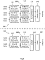
- a downlink system is shown in figure 1 .
- the transmitter 100 comprises, on the one hand, a Ka-Band side and on the other hand an X-Band side.
- Each of the two sides comprises modulators 110, amplifiers 120, switch matrix/switch 130 and 150 and OMUX (output multiplexer) filter/ filter 140 and 160.
- Both terms "switch matrix” and “switch” can be used interchangeably within this disclosure, as well as the terms “OMUX filter” and "filter”.
- respective input data is input to the Ka-Band modulators 110, which modulate the respective input data directly to the Ka-Band.
- the respective modulated input data is then fed to the respective one of the Ka-Band amplifiers 120.
- the Ka-Band amplifiers amplify the Ka-Band signal from the Ka-Band modulators 110 to a power, which is sufficient for a downlink from a satellite to earth. After amplification of each of the Ka-Band signals by the amplifiers 120, all the amplifier output signals are input to a switch matrix 130, which is adapted to switch the activated Ka-Band transmission channels to the OMUX filter 140.
- the Ka-Band transmission channels in figure 1 comprise the Ka-Band modulators and Ka-Band amplifiers respectively. Thus, in figure 1 there are three different Ka-Band transmission channels.
- Not all three Ka-Band transmission channels are simultaneously input to the OMUX filter 140, but only activated Ka-Band transmission channels, such that only two of the three Ka-Band transmission channels are to be transmitted, and that the switch matrix 130 is configured to direct or provide two switch matrix output signals corresponding to the two activated Ka-Band transmission channels to the OMUX filter 140.
- the OMUX filter 140 is then adapted to combine the two switch matrix output signals to exactly one antenna, such that the two switch matrix output signals are separated by frequency within exactly one signal to be transmitted over the antenna.
- the other part of the transmitter 100 in the X-Band comprises X-Band modulators 110, X-Band amplifiers 130, a switch 150 and a filter 160.
- Input data is input to the respective X-Band modulator 110, which is configured to modulate the input data onto a signal within the X-Band.
- Each of the X-Band modulators 110 then feeds a respective one of the X-Band amplifiers 130.
- the transmitter 200 comprises, on the one hand, a Ka-Band side and on the other hand an X-Band side.
- the transmitter 200 comprises Ka-Band modulators 210, Ka-Band amplifiers 220, a switch matrix 230 and an OMUX filter 240.
- the transmitter 200 works by receiving input data respectively on inputs of the Ka-Band modulators 210.
- the Ka-Band modulators 210 respectively modulate the respective input data to a Ka-Band signal and then feed the respective Ka-Band signal to a Ka-Band amplifier 220.
- the respective Ka-Band amplifiers 220 then feed their respective amplified signals with a signal level sufficient for an earth receiver to a switch matrix 230.
- the switch matrix 230 switches the amplified signals to an OMUX filter 240.
- the switch matrix 230 receives, in figure 2 , three amplified signals and feeds two output signals to the OMUX filter 240.
- the two output signals correspond to the number of activated transmission channels which are to be transmitted via the antenna.
- the OMUX filter 240 filters undesired frequency parts, such that only the desired frequency parts are to be transmitted via the antenna. Further, the OMUX filter 240 can combine two signals separated by frequency to one signal having two separate frequency bands/channels within the Ka-Band.
- the transmitter 200 further comprises on the X-Band side, three X-Band modulators 210, three X-Band amplifiers 230, one switch matrix 250 and one filter 260.
- Each X-Band modulator 210 receives respective input data and modulates the input data in the frequency domain to an X-Band.
- the X-Band signal of the respective X-Band modulator output is then fed to an X-Band amplifier 230 respectively for every X-Band modulator output.
- the X-Band amplifier 230 then amplifies the respective X-Band signal to a signal level, such that it can be received by a receiver on earth.
- the amplified signal from the X-Band amplifier 230 is then fed to a switch matrix 250.
- the switch matrix 250 has three feed lines connected to the respective X-Band amplifiers and is able to switch two amplified signals of two activated transmission channels of the three different possible transmission channels to the filter 260.
- the filter 260 filters undesired frequency parts and outputs two different signals to the common antenna which provides orthogonal polarization directions Pol.1 and Pol.2 which are transmitted in the same X-band.
- Figure 1 and figure 2 provide a transmitter concept for a downlink system provided on a satellite for a satellite-to-earth downlink system.
- the main disadvantage of this concept lies within the two separated transmitter elements for Ka-Band, on the one hand, and X-Band, on the other hand, as illustrated by a dashed line in figure 1 and figure 2 , separately.
- the present invention therefore provides a decreased number of hardware elements within a transmitter and further develops the concept of the transmitter as shown in figure 1 and figure 2 by combining hardware elements and making room for other important payload parameters on a satellite. Thus, further costs for an overall satellite system can be decreased.
- FIG. 3 shows a schematic illustration of a transmitter 300.
- the transmitter 300 comprises three modulators 310, three Ka-Band amplifiers 320, two X-Band amplifiers 330, one switch matrix 340, one OMUX filter 350, one switch 360, one filter 370 and two antennas 391 and 392.
- the connections (illustrated as solid and dashed line arrows in figure 3 ) between the respective units (310, 320, 365, 391, 392) of the transmitter 400 are established via high frequency components, such as waveguides, hollow waveguides or coaxial cables.
- the transmitter 300 further comprises a control unit 380.
- the transmitter 300 can further comprise another control unit 380, however is not restricted to a number of control units 380, such that one or each of the control units 380 is able to control each of the X-Band amplifiers and each of the Ka-Band amplifiers.
- the switch matrix 340 can also be understood as switch.
- the OMUX filter 350 can also be understood as filter.
- the switch matrix 340 and OMUX filter 350 as well as the switch 360 and the filter 370 can be understood as a switching and filtering unit 365, respectively, such that the switching and filtering unit 365 can respectively comprise a switch 340/360 and a filter 350/370 operative with each other.
- Each of the three modulators is able to receive different and same input data.
- the input data is then modulated onto a signal in the X-Band by the X-Band modulator 310.
- the input data is received from a data source like an instrument, a storage or mass memory (not illustrated).
- the modulators 310 can take over the step of coding and partly the step of formatting.
- the X-Band modulated input data is then fed from the respective one of the modulators 310 to the respective one of the X-Band amplifiers 330. This applies to all three X-Band modulators 310, respectively.
- the X-Band modulated signal of any one of the modulators 310a, 310b and 310c is modulated/upconverted to the Ka-Band.
- Each of the upconverted Ka-Band signals comprises the respective input data and is then fed from the respective modulators 310a, 310b and 310c to the respective Ka-Band amplifiers 320a, 320b (not illustrated in figure 3 ) and 320c.
- Each of the Ka-Band amplifiers 320 is adapted to amplify the respective Ka-Band signal received from the respective one of the modulators 310.
- the X-Band amplifiers 330a and 330b are adapted to also amplify the respective X-Band signal received from the respective modulators 310.
- transmission channels to be activated and to be transmitted via the antennas 391 and 392 are selected by the one or more control units 380.
- the one or more control units 380 are adapted to selectively activate the Ka-Band amplifiers 320 and X-Band amplifiers 330 depending on the number of transmission channels per Ka-Band or X-Band to be transmitted, respectively.
- three Ka-Band transmission channels are provided comprising the Ka-Band amplifiers 320. Further, in figure 3 , two of the three Ka-Band transmission channels are switched by the switch matrix 340 to the OMUX filter 350. The OMUX filter 350 is then able to multiplex the so received two Ka-Band signals of the two activated transmission channels. The OMUX filter 350 is able to combine the two Ka-Band signals to exactly one signal being separated by frequency and transmitted via the antenna 392 with a same polarization, for example a circular polarization.
- each of the two X-Band transmission channels can be switched on and off by the control unit 380 via activating or deactivating the respective X-Band amplifiers 330.
- the switch 360 can then provide the filter 370 with the respective signal of the activated X-Band transmission channel.
- the filter 370 filters out undesired frequency parts, for example higher or lower than the X-Band. Afterwards, the filtered X-Band signal is fed to the antenna 391.
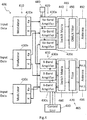
- the transmitter 400 comprises three modulators 410 with each modulator 410a, 410b and 410c having two outputs for X-Band and Ka-Band.
- the transmitter 400 further comprises three Ka-Band amplifiers 420 and three X-Band amplifiers 430.
- the transmitter 400 further comprises one or more control units 480, an X-Band switch matrix 460, a Ka-Band switch matrix 440, a filter for X-Band 470, a Ka-band OMUX filter 450, and antenna 391 for X-Band and an antenna 392 for Ka-Band.
- the switch matrices 440 and 460 can also be understood as switches.
- the OMUX filter 450 can also be understood as filter.
- the switch matrix 440 and OMUX filter 450 as well as the switch 460 and the filter 470 can be understood as a switching and filtering unit 465, as in figure 3 , such that the switching and filtering unit 465 can respectively comprise the switch 440/460 and the filter 450/470 operative with each other.
- the connections (illustrated as solid and dashed line arrows in figure 4 ) between the respective units (410, 420, 465, 491, 492) of the transmitter 400 are established via high frequency components, such as waveguides, hollow waveguides or coaxial cables. Input data is fed to a respective one 410a of the modulators 410.
- the modulator 410a then modulates the input data onto an X-Band. Before the input data is received from a storage device or mass memory (not illustrated), the input data is first formatted and encoded. The X-Band modulated signal is then fed to the X-Band amplifier 430a, as well as upconverted to the Ka-Band and then fed to the Ka-Band amplifier 420a. The same applies to the respective other modulators 410 and amplifiers 420. Together with the other signals amplified by the respective X-Band amplifiers 420, all the X-Band amplified signals are then fed to the switch matrix 460 (in X-Band), when the respective X-Band transmission channel is activated.
- the switch matrix 460 (in X-Band) switches the signals corresponding to the activated X-Band transmission channel to the filter 470.
- the filter 470 filters out undesired frequency parts outside the X-Band.
- the activated X-Band transmission channels comprise the X-Band amplifiers 430a and 430c, such that both provide the switch matrix with a respective X-Band amplified signal which is then respectively fed to the filter 470, which filters out undesired frequency parts.
- the two filtered signals have two orthogonal polarizations to be transmitted via the antenna 491, such that a data rate can be doubled, even if the two X-Band signals to be transmitted have the same channel within the frequency band.
- the two polarizations can be provided for example by an ortho-mode transducer in the antenna.
- the upconverted Ka-Band signal input to the Ka-Band amplifier 420a is amplified and fed to the switch matrix 440.
- the switch matrix 440 switches two signals of two activated Ka-Band transmission channels of three available Ka-Band transmission channels in figure 4 to the OMUX filter 450.
- the OMUX filter 450 is able to provide the antenna 392 with one combined signal by multiplexing and filtering undesired frequency parts aside the Ka-Band.
- the antenna 392 is fed by the OMUX filter 450 with a signal having two frequency channels in the Ka-Band corresponding to the two frequency divided signals multiplexed by the OMUX filter 450.
- the antenna 392 is able to be of a circular polarization and is able to transmit two frequency bands having different mid-frequencies in the Ka-Band.
- the amplifiers for X-Band and Ka-Band can be travelling-wave tube amplifiers, TWTA, or solid state power amplifiers, SSPA. Since TWTA deliver higher output power needed for higher frequencies (see free space loss), TWTA is preferred for Ka-Band and TWTA or SSPA is preferred for X-Band to reduce power consumption. In the case of two transmission channels in either of Ka-Band and X-Band, one of the modulators (illustrated in figures 3 and 4 ) can be omitted.
- An advantageous effect of the present invention is the reduction of the number of necessary interfaces between input data sources and Ka-Band and X-Band transmission channels.
- FIG. 5 schematically illustrates a modulator 510 as described above in figure 3 and figure 4 being able to output X-Band and Ka-Band signals.
- the modulator 510 comprises a modulation and encoding unit 514 and a frequency conversion unit 516.
- the modulator 510 receives input data, formats, encodes and modulates, via the modulation and encoding unit 514, the input data onto a first frequency band, hereinabove described as X-Band. After modulation and coding, the input data is then provided to the frequency conversion unit 516.
- the frequency conversion unit 516 upconverts the X-Band modulated signal to a Ka-Band modulated signal comprising the input data.
- the input data can be provided via the modulator 510 in X-Band and in Ka-Band via X-Band and Ka-Band outputs (X and Ka).
- the main advantage of the present invention as embodied by figures 3 , 4 and 5 is saving hardware by minimizing the amount of input data to be fed to a respective modulator, such that interface circuitries and memory can be saved. Further the amount of hardware necessary for the respective transmission channels usually provided separately in each of the X-Band and the Ka-Bands for downlink from satellite-to-earth can be reduced.
Landscapes
- Engineering & Computer Science (AREA)
- Computer Networks & Wireless Communication (AREA)
- Signal Processing (AREA)
- Physics & Mathematics (AREA)
- Astronomy & Astrophysics (AREA)
- Aviation & Aerospace Engineering (AREA)
- General Physics & Mathematics (AREA)
- Power Engineering (AREA)
- Transmitters (AREA)
Abstract
Description
- The present disclosure is directed to a transmitter for a dual-frequency satellite-to-earth downlink.
- In downlink systems from a satellite to earth, X-Band and Ka-Band frequencies are used to be transmitted via two separated transmission paths separated from each other underlying the disadvantage of having a lot of hardware to be fed with power and occupying space on a respective transmitter board. The respective transmitter board itself should be very small with respect to the satellite's payload parameters, such that hardware minimization in terms of size is a driving goal in satellite construction. However, current implementations of transmitters in satellites still provide for each separate channel separate input data and separate modules, such that each transmission channel works independent of each other, which increases the amount of hardware used in the transmitter implementation.
- Thus, it is an object of the present invention to reduce the amount of hardware in a transmitter.
- According to a first aspect, a transmitter for a dual-frequency satellite-to-earth downlink is provided. The transmitter comprises a plurality of modulators, a first plurality of amplifiers and a second plurality of amplifiers. Each of the plurality of modulators is configured to modulate respective input data onto a respective one of a first plurality of signals in a first frequency band and to modulate the respective one of the first plurality of signals onto a respective one of a second plurality of signals in a second frequency band, or each of the plurality of modulators is configured to modulate respective input data onto a respective one of a first plurality of signals in a first frequency band and to modulate the respective input data onto a respective one of a second plurality of signals in a second frequency band.
- Each of the first plurality of amplifiers is configured to amplify a respective one of the first plurality of signals to at least a first predetermined signal strength. Each of the second plurality of amplifiers is configured to amplify a respective one of the second plurality of signals to at least a second predetermined signal strength. A number of the plurality of modulators is smaller than a sum of a number of the first plurality of amplifiers and the second plurality of amplifiers.
- This has the advantage of minimizing input data and minimizing the amount of memory used for providing the input data.
- The respective input data can be the same or different for each of the plurality of modulators. This can further minimize an amount of memory to be used for providing the input data to the transmitter.
- The first frequency band can be an X-Band and the second frequency band can be a Ka-Band.
- Each of the plurality of modulators can be configured to modulate the respective one of the first plurality of signals onto the respective one of the second plurality of signals by mixing the respective one of the first plurality of signals with a carrier signal having a frequency of a mid-frequency of the second frequency band minus a mid-frequency of a respective one of a plurality of channels in the first frequency band. The respective one of the first plurality of signals can be transmitted on the respective one of the plurality of channels.
- The first and second predetermined signal strengths can each be at least sufficient for the dual-frequency satellite-to-earth downlink such that a receiver on earth can be enabled to demodulate and extract the respective input data.
- The first predetermined signal strength can be smaller than the second predetermined signal strength. In Ka-Band more power is to be provided than in the X-Band.
- The first and second frequency bands can be used for the dual-frequency satellite-to-earth downlink.
- A respective one of a first plurality of transmission channels can at least comprise a respective one of the first plurality of amplifiers. A respective one of a second plurality of transmission channels can at least comprise a respective one of the second plurality of amplifiers. The transmitter can further comprise a control unit. The control unit can be configured to selectively activate or deactivate the respective one of the first plurality of transmission channels. The control unit can further be configured to selectively activate or deactivate the respective one of the second plurality of transmission channels.
- Thus, by switching on and off respective transmission channels in the transmitter, the deactivated amplifiers save power, because they are not used.
- The control unit can be configured to activate the respective one of the first plurality of transmission channels, when the respective one of the first plurality of transmission channels is to be used for the dual-frequency satellite-to-earth downlink. The control unit can further be configured to deactivate the respective one of the first plurality of transmission channels, when the respective one of the first plurality of transmission channels is not to be used for the dual-frequency satellite-to-earth downlink. The control unit can be configured to activate the respective one of the second plurality of transmission channels, when the respective one of the second plurality of transmission channels is to be used for the dual-frequency satellite-to-earth downlink. The control unit can further be configured to deactivate the respective one of the second plurality of transmission channels, when the respective one of the second plurality of transmission channels is not to be used for the dual-frequency satellite-to-earth downlink.
- The transmitter can further comprise a first switching and filtering unit and a second switching and filtering unit. The first switching and filtering unit can be configured to provide, in the case of exactly one activated transmission channel of the first plurality of transmission channels, the respective one of the first plurality of signals to a first antenna, and configured to combine, in the case of exactly two activated transmission channels of the first plurality of transmission channels, the respective two of the first plurality of signals to two orthogonally polarized signals and configured to provide the two orthogonally polarized signals to the first antenna. The second switching and filtering unit can be configured to provide, in the case of exactly one activated transmission channel of the second plurality of transmission channels, the respective one of the second plurality of signals to a second antenna, and configured to combine, in the case of exactly two activated transmission channels of the second plurality of transmission channels, the respective two of the second plurality of signals to a combined signal separated by frequency and configured to provide the combined signal to the second antenna.
- This has the advantage to maximize an output in a respective frequency band. Thus, power can be reduced by minimizing a bandwidth or using orthogonality of transmitted electromagnetic waves.
- The first and second antennas can be the same. The first antenna can be the second antenna.
- The transmitter can further comprise the first antenna and the second antenna. The first antenna can be configured to be impedance matched with the first frequency band and configured to transmit orthogonally polarized electromagnetic waves. The second antenna can be configured to be impedance matched with the second frequency band and configured to transmit electromagnetic waves in one polarization direction.
- The control unit can further be configured to selectively activate or deactivate the respective one of the first plurality of transmission channels by providing a first control signal to switch off the respective one of the first plurality of amplifiers included in the respective one of the first plurality of transmission channels. The control unit can further be configured to selectively activate or deactivate the respective one of the second plurality of transmission channels by providing a second control signal to switch off the respective one of the second plurality of amplifier included in the respective one of the second plurality of transmission channels.
- Hereby, deterioration can be minimized by switching between different amplifiers. Thus life expectancy of Ka-Band and X-Band amplifiers is increased.
- It is clear to a person skilled in the art that the statements set forth herein under use of hardware circuits, software means or a combination thereof may be implemented. The software means can be related to programmed microprocessors or a general computer, an ASIC (Application Specific Integrated Circuit) and/or DSPs (Digital Signal Processors). For example, a memory, signal processing unit, the transmitter and the control unit may be implemented partially as a computer, a logical circuit, an FPGA (Field Programmable Gate Array), a processor (for example, a microprocessor, microcontroller (µC) or an array processor)/a core/a CPU (Central Processing Unit), an FPU (Floating Point Unit), NPU (Numeric Processing Unit), an ALU (Arithmetic Logical Unit), a Coprocessor (further microprocessor for supporting a main processor (CPU)), a GPGPU (General Purpose Computation on Graphics Processing Unit), a multi-core processor (for parallel computing, such as simultaneously performing arithmetic operations on multiple main processor(s) and/or graphical processor(s)) or a DSP. It is further clear to the person skilled in the art that even if the herein-described details will be described in terms of a method, these details may also be implemented or realized in a suitable device, a computer processor or a memory connected to a processor, wherein the memory can be provided with one or more programs that perform the method, when executed by the processor. Therefore, methods like swapping and paging can be deployed.
- Even if some of the aspects described above and below have been described in reference to a modulator or modulators, these aspects may also apply to the transmitter. Likewise, the aspects described above and below in relation to the transmitter may be applicable in a corresponding manner to the modulator(s).
- Other objects, features, advantages and applications will become apparent from the following description of non-limiting embodiments regarding the accompanying drawings. In the drawings, all described and/or illustrated features, alone or in any combination form the subject matter disclosed therein, irrespective of their grouping in the claims or their relations/references. The dimensions and proportions of components or parts shown in the figures are not necessarily to scale; these dimensions and proportions may differ from illustrations in the figures and implemented embodiments.
- Figure 1
- shows a schematic illustration of a transmitter;
- Figure 2
- shows another schematic illustration of a transmitter;
- Figure 3
- shows a schematic illustration of a transmitter with a smaller number of modulators;
- Figure 4
- shows another schematic illustration of a transmitter with a smaller number of modulators; and
- Figure 5
- shows a schematic illustration of a modulator.
- The variants of the functional and operational aspects as well as their functional and operational aspects described herein are only for a better understanding of its structure, its functions and properties; they do not limit the disclosure to the embodiments. The figures are partially schematic, said essential properties and effects are clearly shown enlarged or scaled down in part to clarify the functions, active principles, embodiments and technical characteristics. Every operation, every principle, every technical aspect and every feature that/which is disclosed in the figures or in the text is/can be combined with all claims, each feature in the text and the other figures, other modes of operation, principles, technical refinements and features that are included in this disclosure, or result from it, so that all possible combinations are assigned to the devices and methods described. They also include combinations of all individual comments in the text, that is, in each section of the description, in the claims and combinations between different variations in the text, in the claims and in the figures, and can be made to subject-matter of further claims. The claims do not limit the disclosure and therefore the possible combinations of all identified characteristics among themselves. All features disclosed are explicitly also individually and in combination with all other features disclosed herein.
- In the figures herein, corresponding or functionally similar components are provided with the same or similar reference numerals. The transmitter and modulator will now be described with respect to the embodiments.
- In the following, without being restricted thereto, specific details are set forth to provide a thorough understanding of the present disclosure. However, it is clear to the skilled person that the present disclosure may be used in other embodiments, which may differ from the details set out below.
- A downlink system is shown in
figure 1 . Thetransmitter 100 comprises, on the one hand, a Ka-Band side and on the other hand an X-Band side. Each of the two sides comprisesmodulators 110,amplifiers 120, switch matrix/switch filter Band modulators 110, which modulate the respective input data directly to the Ka-Band. The respective modulated input data is then fed to the respective one of the Ka-Band amplifiers 120. The Ka-Band amplifiers amplify the Ka-Band signal from the Ka-Band modulators 110 to a power, which is sufficient for a downlink from a satellite to earth. After amplification of each of the Ka-Band signals by theamplifiers 120, all the amplifier output signals are input to aswitch matrix 130, which is adapted to switch the activated Ka-Band transmission channels to theOMUX filter 140. The Ka-Band transmission channels infigure 1 comprise the Ka-Band modulators and Ka-Band amplifiers respectively. Thus, infigure 1 there are three different Ka-Band transmission channels. Not all three Ka-Band transmission channels are simultaneously input to theOMUX filter 140, but only activated Ka-Band transmission channels, such that only two of the three Ka-Band transmission channels are to be transmitted, and that theswitch matrix 130 is configured to direct or provide two switch matrix output signals corresponding to the two activated Ka-Band transmission channels to theOMUX filter 140. TheOMUX filter 140 is then adapted to combine the two switch matrix output signals to exactly one antenna, such that the two switch matrix output signals are separated by frequency within exactly one signal to be transmitted over the antenna. - The other part of the
transmitter 100 in the X-Band comprisesX-Band modulators 110,X-Band amplifiers 130, aswitch 150 and afilter 160. Input data is input to the respectiveX-Band modulator 110, which is configured to modulate the input data onto a signal within the X-Band. Each of theX-Band modulators 110 then feeds a respective one of theX-Band amplifiers 130. In a respective way other input data is modulated onto another signal in X-Band and then amplified by another respective one of theX-Band amplifiers 130, as shown by the two respective X-Band transmission channels, each comprising one of theX-Band modulators 110 and the respective X-Band amplifier 130 (connection illustrated by an arrow from the respective one of theX-Band modulators 110 to the respective one of the X-Band amplifiers 130). After amplification to a signal level sufficient for an earth receiver, each of the two amplified X-Band signals is input to theswitch 150, such that two input signals are output to afilter 160, which filters undesired frequency parts. After filtering by thefilter 160, the signal is fed to an antenna. - In
figure 2 , the same concept applies as forfigure 1 . Thetransmitter 200 comprises, on the one hand, a Ka-Band side and on the other hand an X-Band side. Thetransmitter 200 comprises Ka-Band modulators 210, Ka-Band amplifiers 220, aswitch matrix 230 and anOMUX filter 240. Thetransmitter 200 works by receiving input data respectively on inputs of the Ka-Band modulators 210. The Ka-Band modulators 210 respectively modulate the respective input data to a Ka-Band signal and then feed the respective Ka-Band signal to a Ka-Band amplifier 220. The respective Ka-Band amplifiers 220 then feed their respective amplified signals with a signal level sufficient for an earth receiver to aswitch matrix 230. Theswitch matrix 230 switches the amplified signals to anOMUX filter 240. Theswitch matrix 230 receives, infigure 2 , three amplified signals and feeds two output signals to theOMUX filter 240. The two output signals correspond to the number of activated transmission channels which are to be transmitted via the antenna. TheOMUX filter 240, on the one hand, filters undesired frequency parts, such that only the desired frequency parts are to be transmitted via the antenna. Further, theOMUX filter 240 can combine two signals separated by frequency to one signal having two separate frequency bands/channels within the Ka-Band. - The
transmitter 200 further comprises on the X-Band side, threeX-Band modulators 210, threeX-Band amplifiers 230, oneswitch matrix 250 and onefilter 260. EachX-Band modulator 210 receives respective input data and modulates the input data in the frequency domain to an X-Band. The X-Band signal of the respective X-Band modulator output is then fed to anX-Band amplifier 230 respectively for every X-Band modulator output. TheX-Band amplifier 230 then amplifies the respective X-Band signal to a signal level, such that it can be received by a receiver on earth. The amplified signal from theX-Band amplifier 230 is then fed to aswitch matrix 250. Theswitch matrix 250 has three feed lines connected to the respective X-Band amplifiers and is able to switch two amplified signals of two activated transmission channels of the three different possible transmission channels to thefilter 260. Thefilter 260 filters undesired frequency parts and outputs two different signals to the common antenna which provides orthogonal polarization directions Pol.1 and Pol.2 which are transmitted in the same X-band. -
Figure 1 andfigure 2 provide a transmitter concept for a downlink system provided on a satellite for a satellite-to-earth downlink system. The main disadvantage of this concept lies within the two separated transmitter elements for Ka-Band, on the one hand, and X-Band, on the other hand, as illustrated by a dashed line infigure 1 andfigure 2 , separately. The present invention therefore provides a decreased number of hardware elements within a transmitter and further develops the concept of the transmitter as shown infigure 1 andfigure 2 by combining hardware elements and making room for other important payload parameters on a satellite. Thus, further costs for an overall satellite system can be decreased. -
Figure 3 shows a schematic illustration of atransmitter 300. Thetransmitter 300 comprises threemodulators 310, three Ka-Band amplifiers 320, twoX-Band amplifiers 330, oneswitch matrix 340, oneOMUX filter 350, oneswitch 360, onefilter 370 and twoantennas figure 3 ) between the respective units (310, 320, 365, 391, 392) of thetransmitter 400 are established via high frequency components, such as waveguides, hollow waveguides or coaxial cables. Thetransmitter 300 further comprises acontrol unit 380. Thetransmitter 300 can further comprise anothercontrol unit 380, however is not restricted to a number ofcontrol units 380, such that one or each of thecontrol units 380 is able to control each of the X-Band amplifiers and each of the Ka-Band amplifiers. Theswitch matrix 340 can also be understood as switch. TheOMUX filter 350 can also be understood as filter. Theswitch matrix 340 andOMUX filter 350 as well as theswitch 360 and thefilter 370 can be understood as a switching andfiltering unit 365, respectively, such that the switching andfiltering unit 365 can respectively comprise aswitch 340/360 and afilter 350/370 operative with each other. Each of the three modulators is able to receive different and same input data. - The input data is then modulated onto a signal in the X-Band by the
X-Band modulator 310. Before modulation of the input data, the input data is received from a data source like an instrument, a storage or mass memory (not illustrated). Further, themodulators 310 can take over the step of coding and partly the step of formatting. The X-Band modulated input data is then fed from the respective one of themodulators 310 to the respective one of theX-Band amplifiers 330. This applies to all threeX-Band modulators 310, respectively. Further, the X-Band modulated signal of any one of the modulators 310a, 310b and 310c is modulated/upconverted to the Ka-Band. Thus, there is a non-direct implementation of an upconversion from the input data to the Ka-Band. Each of the upconverted Ka-Band signals comprises the respective input data and is then fed from therespective modulators Band amplifiers 320a, 320b (not illustrated infigure 3 ) and 320c. Each of the Ka-Band amplifiers 320 is adapted to amplify the respective Ka-Band signal received from the respective one of themodulators 310. Further, theX-Band amplifiers respective modulators 310. Further, transmission channels to be activated and to be transmitted via theantennas more control units 380. The one ormore control units 380 are adapted to selectively activate the Ka-Band amplifiers 320 andX-Band amplifiers 330 depending on the number of transmission channels per Ka-Band or X-Band to be transmitted, respectively. - In
figure 3 , three Ka-Band transmission channels are provided comprising the Ka-Band amplifiers 320. Further, infigure 3 , two of the three Ka-Band transmission channels are switched by theswitch matrix 340 to theOMUX filter 350. TheOMUX filter 350 is then able to multiplex the so received two Ka-Band signals of the two activated transmission channels. TheOMUX filter 350 is able to combine the two Ka-Band signals to exactly one signal being separated by frequency and transmitted via theantenna 392 with a same polarization, for example a circular polarization. Further, infigure 3 , two X-Band transmission channels are provided, such that each of the two X-Band transmission channels can be switched on and off by thecontrol unit 380 via activating or deactivating therespective X-Band amplifiers 330. Theswitch 360 can then provide thefilter 370 with the respective signal of the activated X-Band transmission channel. Thefilter 370 then filters out undesired frequency parts, for example higher or lower than the X-Band. Afterwards, the filtered X-Band signal is fed to theantenna 391. - Further, a schematic illustration of a
transmitter 400 is shown infigure 4 . Thetransmitter 400 comprises threemodulators 410 with each modulator 410a, 410b and 410c having two outputs for X-Band and Ka-Band. Thetransmitter 400 further comprises three Ka-Band amplifiers 420 and three X-Band amplifiers 430. Thetransmitter 400 further comprises one ormore control units 480, anX-Band switch matrix 460, a Ka-Band switch matrix 440, a filter forX-Band 470, a Ka-band OMUX filter 450, andantenna 391 for X-Band and anantenna 392 for Ka-Band. Theswitch matrices OMUX filter 450 can also be understood as filter. Theswitch matrix 440 andOMUX filter 450 as well as theswitch 460 and thefilter 470 can be understood as a switching andfiltering unit 465, as infigure 3 , such that the switching andfiltering unit 465 can respectively comprise theswitch 440/460 and thefilter 450/470 operative with each other. The connections (illustrated as solid and dashed line arrows infigure 4 ) between the respective units (410, 420, 465, 491, 492) of thetransmitter 400 are established via high frequency components, such as waveguides, hollow waveguides or coaxial cables. Input data is fed to a respective one 410a of themodulators 410. Themodulator 410a then modulates the input data onto an X-Band. Before the input data is received from a storage device or mass memory (not illustrated), the input data is first formatted and encoded. The X-Band modulated signal is then fed to the X-Band amplifier 430a, as well as upconverted to the Ka-Band and then fed to the Ka-Band amplifier 420a. The same applies to the respectiveother modulators 410 andamplifiers 420. Together with the other signals amplified by therespective X-Band amplifiers 420, all the X-Band amplified signals are then fed to the switch matrix 460 (in X-Band), when the respective X-Band transmission channel is activated. The switch matrix 460 (in X-Band) switches the signals corresponding to the activated X-Band transmission channel to thefilter 470. Thefilter 470 filters out undesired frequency parts outside the X-Band. For example, the activated X-Band transmission channels comprise theX-Band amplifiers 430a and 430c, such that both provide the switch matrix with a respective X-Band amplified signal which is then respectively fed to thefilter 470, which filters out undesired frequency parts. The two filtered signals have two orthogonal polarizations to be transmitted via theantenna 491, such that a data rate can be doubled, even if the two X-Band signals to be transmitted have the same channel within the frequency band. The two polarizations can be provided for example by an ortho-mode transducer in the antenna. Further, the upconverted Ka-Band signal input to the Ka-Band amplifier 420a is amplified and fed to theswitch matrix 440. Theswitch matrix 440 switches two signals of two activated Ka-Band transmission channels of three available Ka-Band transmission channels infigure 4 to theOMUX filter 450. TheOMUX filter 450 is able to provide theantenna 392 with one combined signal by multiplexing and filtering undesired frequency parts aside the Ka-Band. Thus, theantenna 392 is fed by theOMUX filter 450 with a signal having two frequency channels in the Ka-Band corresponding to the two frequency divided signals multiplexed by theOMUX filter 450. Thus, theantenna 392 is able to be of a circular polarization and is able to transmit two frequency bands having different mid-frequencies in the Ka-Band. - In
figure 3 and4 , the amplifiers for X-Band and Ka-Band can be travelling-wave tube amplifiers, TWTA, or solid state power amplifiers, SSPA. Since TWTA deliver higher output power needed for higher frequencies (see free space loss), TWTA is preferred for Ka-Band and TWTA or SSPA is preferred for X-Band to reduce power consumption. In the case of two transmission channels in either of Ka-Band and X-Band, one of the modulators (illustrated infigures 3 and4 ) can be omitted. An advantageous effect of the present invention is the reduction of the number of necessary interfaces between input data sources and Ka-Band and X-Band transmission channels. -
Figure 5 schematically illustrates amodulator 510 as described above infigure 3 andfigure 4 being able to output X-Band and Ka-Band signals. Themodulator 510 comprises a modulation andencoding unit 514 and afrequency conversion unit 516. Themodulator 510 receives input data, formats, encodes and modulates, via the modulation andencoding unit 514, the input data onto a first frequency band, hereinabove described as X-Band. After modulation and coding, the input data is then provided to thefrequency conversion unit 516. Thefrequency conversion unit 516 upconverts the X-Band modulated signal to a Ka-Band modulated signal comprising the input data. Thus, the input data can be provided via themodulator 510 in X-Band and in Ka-Band via X-Band and Ka-Band outputs (X and Ka). - The main advantage of the present invention as embodied by
figures 3 ,4 and5 , is saving hardware by minimizing the amount of input data to be fed to a respective modulator, such that interface circuitries and memory can be saved. Further the amount of hardware necessary for the respective transmission channels usually provided separately in each of the X-Band and the Ka-Bands for downlink from satellite-to-earth can be reduced. - The invention is not limited in any way to the embodiments described above. On the contrary, there are many possibilities for modifications thereof, which are apparent to an average skilled person without departing from the underlying idea of the invention as defined in the appended claims.
Claims (12)
- A transmitter (300; 400) for a dual-frequency satellite-to-earth downlink, the transmitter (300; 400) comprising:a plurality of modulators (310; 410), wherein each of the plurality of modulators (310; 410) is configured to modulate respective input data onto a respective one of a first plurality of signals in a first frequency band and to modulate the respective one of the first plurality of signals onto a respective one of a second plurality of signals in a second frequency band, orto modulate respective input data onto a respective one of a first plurality of signals in a first frequency band and to modulate the respective input data onto a respective one of a second plurality of signals in a second frequency band;a first plurality of amplifiers (330; 430), wherein each of the first plurality of amplifiers (330; 430) is configured to amplify a respective one of the first plurality of signals to at least a first predetermined signal strength;a second plurality of amplifiers (320; 420), wherein each of the second plurality of amplifiers (320; 420) is configured to amplify a respective one of the second plurality of signals to at least a second predetermined signal strength; andwherein a number of the plurality of modulators (310; 410) is smaller than a sum of a number of the first plurality of amplifiers (330; 430) and the second plurality of amplifiers (320; 420).
- The transmitter (300; 400) according to claim 1, wherein the respective input data is the same or different for each of the plurality of modulators (310; 410).
- The transmitter (300; 400) according to claims 1 or 2, wherein the first frequency band is an X-Band and the second frequency band is a Ka-Band.
- The transmitter (300; 400) according to any one of the foregoing claims, wherein each of the plurality of modulators (310; 410) is configured to modulate the respective one of the first plurality of signals onto the respective one of the second plurality of signals by mixing the respective one of the first plurality of signals with a carrier signal having a frequency of a mid-frequency of the second frequency band minus a mid-frequency of a respective one of a plurality of channels in the first frequency band, wherein the respective one of the first plurality of signals is to be transmitted on the respective one of the plurality of channels.
- The transmitter (300; 400) according to any one of the foregoing claims, wherein the first and second predetermined signal strengths are each at least sufficient for the dual-frequency satellite-to-earth downlink such that a receiver on earth is enabled to demodulate and extract the respective input data.
- The transmitter (300; 400) according to any one of the foregoing claims, wherein the first and second frequency bands are to be used for the dual-frequency satellite-to-earth downlink.
- The transmitter (300; 400) according to any one of the foregoing claims,
wherein a respective one of a first plurality of transmission channels at least comprises a respective one of the first plurality of amplifiers (330; 430), and
wherein a respective one of a second plurality of transmission channels at least comprises a respective one of the second plurality of amplifiers (320; 420); and
wherein the transmitter (300; 400) further comprises:a control unit (380; 480) configured to selectively activate or deactivate the respective one of the first plurality of transmission channels, andthe control unit (380; 480) is further configured to selectively activate or deactivate the respective one of the second plurality of transmission channels. - The transmitter (300; 400) according to claim 7,
wherein the control unit (380; 480) is configured to activate the respective one of the first plurality of transmission channels, when the respective one of the first plurality of transmission channels is to be used for the dual-frequency satellite-to-earth downlink, and wherein the control unit (380; 480) is further configured to deactivate the respective one of the first plurality of transmission channels, when the respective one of the first plurality of transmission channels is not to be used for the dual-frequency satellite-to-earth downlink; and
wherein the control unit (380; 480) is configured to activate the respective one of the second plurality of transmission channels, when the respective one of the second plurality of transmission channels is to be used for the dual-frequency satellite-to-earth downlink, and wherein the control unit (380; 480) is further configured to deactivate the respective one of the second plurality of transmission channels, when the respective one of the second plurality of transmission channels is not to be used for the dual-frequency satellite-to-earth downlink. - The transmitter (300; 400) according to claims 7 or 8, wherein the transmitter (300; 400) further comprises:a first switching and filtering unit (360, 370; 460, 470) configured to provide, in the case of exactly one activated transmission channel of the first plurality of transmission channels, the respective one of the first plurality of signals to a first antenna (391; 491), and configured to combine, in the case of exactly two activated transmission channels of the first plurality of transmission channels, the respective two of the first plurality of signals to two orthogonally polarized signals and configured to provide the two orthogonally polarized signals to the first antenna (391; 491); anda second switching and filtering unit (360, 370; 460, 470) configured to provide, in the case of exactly one activated transmission channel of the second plurality of transmission channels, the respective one of the second plurality of signals to a second antenna (392; 492), and configured to combine, in the case of exactly two activated transmission channels of the second plurality of transmission channels, the respective two of the second plurality of signals to a combined signal separated by frequency and configured to provide the combined signal to the second antenna (392; 492).
- The transmitter (300; 400) according to claim 9, wherein the first antenna is the second antenna.
- The transmitter (300; 400) according to claims 9 or 10, wherein the transmitter (300; 400) further comprises:the first antenna (391; 491) configured to be impedance matched with the first frequency band and configured to transmit orthogonally polarized electromagnetic waves; andthe second antenna (392; 492) configured to be impedance matched with the second frequency band and configured to transmit electromagnetic waves in one polarization direction.
- The transmitter (300; 400) according to any one of claims 7 to 11,
wherein the control unit (380; 480) is further configured to selectively activate or deactivate the respective one of the first plurality of transmission channels by providing a first control signal to switch off the respective one of the first plurality of amplifiers (330; 430) included in the respective one of the first plurality of transmission channels, and
wherein the control unit (380; 480) is further configured to selectively activate or deactivate the respective one of the second plurality of transmission channels by providing a second control signal to switch off the respective one of the second plurality of amplifier (320; 420) included in the respective one of the second plurality of transmission channels.
Priority Applications (2)
| Application Number | Priority Date | Filing Date | Title |
|---|---|---|---|
| EP17168651.2A EP3396870B1 (en) | 2017-04-28 | 2017-04-28 | Dual-frequency downlink transmitter |
| US15/954,850 US10411791B2 (en) | 2017-04-28 | 2018-04-17 | Dual-frequency downlink transmitter |
Applications Claiming Priority (1)
| Application Number | Priority Date | Filing Date | Title |
|---|---|---|---|
| EP17168651.2A EP3396870B1 (en) | 2017-04-28 | 2017-04-28 | Dual-frequency downlink transmitter |
Publications (2)
| Publication Number | Publication Date |
|---|---|
| EP3396870A1 true EP3396870A1 (en) | 2018-10-31 |
| EP3396870B1 EP3396870B1 (en) | 2023-11-01 |
Family
ID=58644940
Family Applications (1)
| Application Number | Title | Priority Date | Filing Date |
|---|---|---|---|
| EP17168651.2A Active EP3396870B1 (en) | 2017-04-28 | 2017-04-28 | Dual-frequency downlink transmitter |
Country Status (2)
| Country | Link |
|---|---|
| US (1) | US10411791B2 (en) |
| EP (1) | EP3396870B1 (en) |
Cited By (1)
| Publication number | Priority date | Publication date | Assignee | Title |
|---|---|---|---|---|
| CN114355388A (en) * | 2021-12-30 | 2022-04-15 | 浙江时空道宇科技有限公司 | Dual-frequency transmitting assembly and system for low-earth-orbit satellite navigation enhancement system |
Citations (2)
| Publication number | Priority date | Publication date | Assignee | Title |
|---|---|---|---|---|
| US20070155319A1 (en) * | 2006-01-04 | 2007-07-05 | Globalstar, Inc. | Satellite communication system for communicating packet data messages |
| WO2016094786A1 (en) * | 2014-12-11 | 2016-06-16 | Space Systems/Loral, Llc | Digital payload with variable high power amplifiers |
Family Cites Families (6)
| Publication number | Priority date | Publication date | Assignee | Title |
|---|---|---|---|---|
| US7366463B1 (en) * | 2000-05-05 | 2008-04-29 | The Directv Group, Inc. | Military UHF and commercial Geo-mobile system combination for radio signal relay |
| US7751779B2 (en) * | 2006-12-21 | 2010-07-06 | Northrop Grumman Space & Mission Systems Corp. | Satellite communication system |
| US20090034475A1 (en) * | 2007-07-17 | 2009-02-05 | Viasat, Inc. | Soft Handoff Using A Multi-Beam Antenna System |
| US9154217B1 (en) * | 2013-10-29 | 2015-10-06 | Anokiwave, Inc. | Direct conversion remote satellite communications terminal |
| CA2883278C (en) * | 2015-02-27 | 2022-03-08 | Asia Satellite Telecommunications Company Limited | Methods and systems for improving spectrum utilization for satellite communications |
| US10263648B2 (en) * | 2017-03-13 | 2019-04-16 | The Boeing Company | Low cost millimeter wave receiver and method for operating same |
-
2017
- 2017-04-28 EP EP17168651.2A patent/EP3396870B1/en active Active
-
2018
- 2018-04-17 US US15/954,850 patent/US10411791B2/en active Active
Patent Citations (2)
| Publication number | Priority date | Publication date | Assignee | Title |
|---|---|---|---|---|
| US20070155319A1 (en) * | 2006-01-04 | 2007-07-05 | Globalstar, Inc. | Satellite communication system for communicating packet data messages |
| WO2016094786A1 (en) * | 2014-12-11 | 2016-06-16 | Space Systems/Loral, Llc | Digital payload with variable high power amplifiers |
Cited By (2)
| Publication number | Priority date | Publication date | Assignee | Title |
|---|---|---|---|---|
| CN114355388A (en) * | 2021-12-30 | 2022-04-15 | 浙江时空道宇科技有限公司 | Dual-frequency transmitting assembly and system for low-earth-orbit satellite navigation enhancement system |
| CN114355388B (en) * | 2021-12-30 | 2023-04-07 | 浙江时空道宇科技有限公司 | Dual-frequency transmitting assembly and system for low-earth-orbit satellite navigation enhancement system |
Also Published As
| Publication number | Publication date |
|---|---|
| EP3396870B1 (en) | 2023-11-01 |
| US10411791B2 (en) | 2019-09-10 |
| US20180316415A1 (en) | 2018-11-01 |
Similar Documents
| Publication | Publication Date | Title |
|---|---|---|
| US5963845A (en) | Satellite payload with integrated transparent channels | |
| EP2487800A1 (en) | Active antenna arrays | |
| EP2461493B1 (en) | Base station antenna device embedded with transmission and receiving module | |
| CN110912576B (en) | Radio frequency structure and communication terminal | |
| WO1994026035B1 (en) | Use of diversity transmission to relax adjacent channel requirements in mobile telephone systems | |
| JP2018110454A (en) | Amplitude tapered switching beam antenna system | |
| US6047162A (en) | Regional programming in a direct broadcast satellite | |
| GB1497430A (en) | Earth terminal for satellite communications | |
| CA2660617C (en) | Broadband amplifying device | |
| US10411791B2 (en) | Dual-frequency downlink transmitter | |
| JP2001168778A (en) | Wireless communication base station | |
| CN113745854A (en) | Phased array transmission multi-beam antenna system | |
| US20210351506A1 (en) | Ultra-small millimeter wave 5g beam former architecture | |
| CN102377440A (en) | Radio frequency front-end circuit | |
| US10097218B2 (en) | Radio frequency circuit and communication device module | |
| US6934514B2 (en) | System for transmitting digital signals with FM signals | |
| CN118264267A (en) | Radio frequency front-end module, electronic device and control method and device thereof | |
| US7019710B1 (en) | Antenna system | |
| CN102648586B (en) | Wireless communication device | |
| NZ506994A (en) | A comb linear amplifier combiner having a bandpass filter coupled to a power amplifier | |
| CN222215728U (en) | Radio frequency circuit, radio frequency device, and electronic equipment | |
| KR102416006B1 (en) | Dual polarized type transmission and receipt antenna apparatus and method for transmitting and receiving of the same | |
| US20250253871A1 (en) | Apparatus for processing radio frequency signals | |
| CN108964692A (en) | Radio circuit and radio frequency system | |
| CN109995337A (en) | A kind of power amplifier and amplification method |
Legal Events
| Date | Code | Title | Description |
|---|---|---|---|
| PUAI | Public reference made under article 153(3) epc to a published international application that has entered the european phase |
Free format text: ORIGINAL CODE: 0009012 |
|
| STAA | Information on the status of an ep patent application or granted ep patent |
Free format text: STATUS: REQUEST FOR EXAMINATION WAS MADE |
|
| 17P | Request for examination filed |
Effective date: 20171201 |
|
| AK | Designated contracting states |
Kind code of ref document: A1 Designated state(s): AL AT BE BG CH CY CZ DE DK EE ES FI FR GB GR HR HU IE IS IT LI LT LU LV MC MK MT NL NO PL PT RO RS SE SI SK SM TR |
|
| AX | Request for extension of the european patent |
Extension state: BA ME |
|
| STAA | Information on the status of an ep patent application or granted ep patent |
Free format text: STATUS: EXAMINATION IS IN PROGRESS |
|
| 17Q | First examination report despatched |
Effective date: 20191016 |
|
| GRAP | Despatch of communication of intention to grant a patent |
Free format text: ORIGINAL CODE: EPIDOSNIGR1 |
|
| STAA | Information on the status of an ep patent application or granted ep patent |
Free format text: STATUS: GRANT OF PATENT IS INTENDED |
|
| INTG | Intention to grant announced |
Effective date: 20230525 |
|
| GRAS | Grant fee paid |
Free format text: ORIGINAL CODE: EPIDOSNIGR3 |
|
| GRAA | (expected) grant |
Free format text: ORIGINAL CODE: 0009210 |
|
| STAA | Information on the status of an ep patent application or granted ep patent |
Free format text: STATUS: THE PATENT HAS BEEN GRANTED |
|
| AK | Designated contracting states |
Kind code of ref document: B1 Designated state(s): AL AT BE BG CH CY CZ DE DK EE ES FI FR GB GR HR HU IE IS IT LI LT LU LV MC MK MT NL NO PL PT RO RS SE SI SK SM TR |
|
| REG | Reference to a national code |
Ref country code: GB Ref legal event code: FG4D |
|
| REG | Reference to a national code |
Ref country code: CH Ref legal event code: EP |
|
| REG | Reference to a national code |
Ref country code: DE Ref legal event code: R096 Ref document number: 602017075917 Country of ref document: DE |
|
| REG | Reference to a national code |
Ref country code: IE Ref legal event code: FG4D |
|
| REG | Reference to a national code |
Ref country code: LT Ref legal event code: MG9D |
|
| REG | Reference to a national code |
Ref country code: NL Ref legal event code: MP Effective date: 20231101 |
|
| PG25 | Lapsed in a contracting state [announced via postgrant information from national office to epo] |
Ref country code: GR Free format text: LAPSE BECAUSE OF FAILURE TO SUBMIT A TRANSLATION OF THE DESCRIPTION OR TO PAY THE FEE WITHIN THE PRESCRIBED TIME-LIMIT Effective date: 20240202 |
|
| PG25 | Lapsed in a contracting state [announced via postgrant information from national office to epo] |
Ref country code: IS Free format text: LAPSE BECAUSE OF FAILURE TO SUBMIT A TRANSLATION OF THE DESCRIPTION OR TO PAY THE FEE WITHIN THE PRESCRIBED TIME-LIMIT Effective date: 20240301 |
|
| PG25 | Lapsed in a contracting state [announced via postgrant information from national office to epo] |
Ref country code: LT Free format text: LAPSE BECAUSE OF FAILURE TO SUBMIT A TRANSLATION OF THE DESCRIPTION OR TO PAY THE FEE WITHIN THE PRESCRIBED TIME-LIMIT Effective date: 20231101 |
|
| REG | Reference to a national code |
Ref country code: AT Ref legal event code: MK05 Ref document number: 1628412 Country of ref document: AT Kind code of ref document: T Effective date: 20231101 |
|
| PG25 | Lapsed in a contracting state [announced via postgrant information from national office to epo] |
Ref country code: NL Free format text: LAPSE BECAUSE OF FAILURE TO SUBMIT A TRANSLATION OF THE DESCRIPTION OR TO PAY THE FEE WITHIN THE PRESCRIBED TIME-LIMIT Effective date: 20231101 |
|
| PG25 | Lapsed in a contracting state [announced via postgrant information from national office to epo] |
Ref country code: AT Free format text: LAPSE BECAUSE OF FAILURE TO SUBMIT A TRANSLATION OF THE DESCRIPTION OR TO PAY THE FEE WITHIN THE PRESCRIBED TIME-LIMIT Effective date: 20231101 |
|
| PG25 | Lapsed in a contracting state [announced via postgrant information from national office to epo] |
Ref country code: ES Free format text: LAPSE BECAUSE OF FAILURE TO SUBMIT A TRANSLATION OF THE DESCRIPTION OR TO PAY THE FEE WITHIN THE PRESCRIBED TIME-LIMIT Effective date: 20231101 |
|
| PG25 | Lapsed in a contracting state [announced via postgrant information from national office to epo] |
Ref country code: NL Free format text: LAPSE BECAUSE OF FAILURE TO SUBMIT A TRANSLATION OF THE DESCRIPTION OR TO PAY THE FEE WITHIN THE PRESCRIBED TIME-LIMIT Effective date: 20231101 Ref country code: LT Free format text: LAPSE BECAUSE OF FAILURE TO SUBMIT A TRANSLATION OF THE DESCRIPTION OR TO PAY THE FEE WITHIN THE PRESCRIBED TIME-LIMIT Effective date: 20231101 Ref country code: IS Free format text: LAPSE BECAUSE OF FAILURE TO SUBMIT A TRANSLATION OF THE DESCRIPTION OR TO PAY THE FEE WITHIN THE PRESCRIBED TIME-LIMIT Effective date: 20240301 Ref country code: GR Free format text: LAPSE BECAUSE OF FAILURE TO SUBMIT A TRANSLATION OF THE DESCRIPTION OR TO PAY THE FEE WITHIN THE PRESCRIBED TIME-LIMIT Effective date: 20240202 Ref country code: ES Free format text: LAPSE BECAUSE OF FAILURE TO SUBMIT A TRANSLATION OF THE DESCRIPTION OR TO PAY THE FEE WITHIN THE PRESCRIBED TIME-LIMIT Effective date: 20231101 Ref country code: BG Free format text: LAPSE BECAUSE OF FAILURE TO SUBMIT A TRANSLATION OF THE DESCRIPTION OR TO PAY THE FEE WITHIN THE PRESCRIBED TIME-LIMIT Effective date: 20240201 Ref country code: AT Free format text: LAPSE BECAUSE OF FAILURE TO SUBMIT A TRANSLATION OF THE DESCRIPTION OR TO PAY THE FEE WITHIN THE PRESCRIBED TIME-LIMIT Effective date: 20231101 Ref country code: PT Free format text: LAPSE BECAUSE OF FAILURE TO SUBMIT A TRANSLATION OF THE DESCRIPTION OR TO PAY THE FEE WITHIN THE PRESCRIBED TIME-LIMIT Effective date: 20240301 |
|
| PG25 | Lapsed in a contracting state [announced via postgrant information from national office to epo] |
Ref country code: SE Free format text: LAPSE BECAUSE OF FAILURE TO SUBMIT A TRANSLATION OF THE DESCRIPTION OR TO PAY THE FEE WITHIN THE PRESCRIBED TIME-LIMIT Effective date: 20231101 Ref country code: RS Free format text: LAPSE BECAUSE OF FAILURE TO SUBMIT A TRANSLATION OF THE DESCRIPTION OR TO PAY THE FEE WITHIN THE PRESCRIBED TIME-LIMIT Effective date: 20231101 Ref country code: PL Free format text: LAPSE BECAUSE OF FAILURE TO SUBMIT A TRANSLATION OF THE DESCRIPTION OR TO PAY THE FEE WITHIN THE PRESCRIBED TIME-LIMIT Effective date: 20231101 Ref country code: NO Free format text: LAPSE BECAUSE OF FAILURE TO SUBMIT A TRANSLATION OF THE DESCRIPTION OR TO PAY THE FEE WITHIN THE PRESCRIBED TIME-LIMIT Effective date: 20240201 Ref country code: LV Free format text: LAPSE BECAUSE OF FAILURE TO SUBMIT A TRANSLATION OF THE DESCRIPTION OR TO PAY THE FEE WITHIN THE PRESCRIBED TIME-LIMIT Effective date: 20231101 Ref country code: HR Free format text: LAPSE BECAUSE OF FAILURE TO SUBMIT A TRANSLATION OF THE DESCRIPTION OR TO PAY THE FEE WITHIN THE PRESCRIBED TIME-LIMIT Effective date: 20231101 |
|
| PG25 | Lapsed in a contracting state [announced via postgrant information from national office to epo] |
Ref country code: DK Free format text: LAPSE BECAUSE OF FAILURE TO SUBMIT A TRANSLATION OF THE DESCRIPTION OR TO PAY THE FEE WITHIN THE PRESCRIBED TIME-LIMIT Effective date: 20231101 |
|
| PG25 | Lapsed in a contracting state [announced via postgrant information from national office to epo] |
Ref country code: CZ Free format text: LAPSE BECAUSE OF FAILURE TO SUBMIT A TRANSLATION OF THE DESCRIPTION OR TO PAY THE FEE WITHIN THE PRESCRIBED TIME-LIMIT Effective date: 20231101 |
|
| PG25 | Lapsed in a contracting state [announced via postgrant information from national office to epo] |
Ref country code: SK Free format text: LAPSE BECAUSE OF FAILURE TO SUBMIT A TRANSLATION OF THE DESCRIPTION OR TO PAY THE FEE WITHIN THE PRESCRIBED TIME-LIMIT Effective date: 20231101 |
|
| PG25 | Lapsed in a contracting state [announced via postgrant information from national office to epo] |
Ref country code: SM Free format text: LAPSE BECAUSE OF FAILURE TO SUBMIT A TRANSLATION OF THE DESCRIPTION OR TO PAY THE FEE WITHIN THE PRESCRIBED TIME-LIMIT Effective date: 20231101 Ref country code: SK Free format text: LAPSE BECAUSE OF FAILURE TO SUBMIT A TRANSLATION OF THE DESCRIPTION OR TO PAY THE FEE WITHIN THE PRESCRIBED TIME-LIMIT Effective date: 20231101 Ref country code: RO Free format text: LAPSE BECAUSE OF FAILURE TO SUBMIT A TRANSLATION OF THE DESCRIPTION OR TO PAY THE FEE WITHIN THE PRESCRIBED TIME-LIMIT Effective date: 20231101 Ref country code: IT Free format text: LAPSE BECAUSE OF FAILURE TO SUBMIT A TRANSLATION OF THE DESCRIPTION OR TO PAY THE FEE WITHIN THE PRESCRIBED TIME-LIMIT Effective date: 20231101 Ref country code: EE Free format text: LAPSE BECAUSE OF FAILURE TO SUBMIT A TRANSLATION OF THE DESCRIPTION OR TO PAY THE FEE WITHIN THE PRESCRIBED TIME-LIMIT Effective date: 20231101 Ref country code: DK Free format text: LAPSE BECAUSE OF FAILURE TO SUBMIT A TRANSLATION OF THE DESCRIPTION OR TO PAY THE FEE WITHIN THE PRESCRIBED TIME-LIMIT Effective date: 20231101 Ref country code: CZ Free format text: LAPSE BECAUSE OF FAILURE TO SUBMIT A TRANSLATION OF THE DESCRIPTION OR TO PAY THE FEE WITHIN THE PRESCRIBED TIME-LIMIT Effective date: 20231101 |
|
| REG | Reference to a national code |
Ref country code: DE Ref legal event code: R097 Ref document number: 602017075917 Country of ref document: DE |
|
| PLBE | No opposition filed within time limit |
Free format text: ORIGINAL CODE: 0009261 |
|
| STAA | Information on the status of an ep patent application or granted ep patent |
Free format text: STATUS: NO OPPOSITION FILED WITHIN TIME LIMIT |
|
| 26N | No opposition filed |
Effective date: 20240802 |
|
| PG25 | Lapsed in a contracting state [announced via postgrant information from national office to epo] |
Ref country code: SI Free format text: LAPSE BECAUSE OF FAILURE TO SUBMIT A TRANSLATION OF THE DESCRIPTION OR TO PAY THE FEE WITHIN THE PRESCRIBED TIME-LIMIT Effective date: 20231101 |
|
| PG25 | Lapsed in a contracting state [announced via postgrant information from national office to epo] |
Ref country code: SI Free format text: LAPSE BECAUSE OF FAILURE TO SUBMIT A TRANSLATION OF THE DESCRIPTION OR TO PAY THE FEE WITHIN THE PRESCRIBED TIME-LIMIT Effective date: 20231101 |
|
| PG25 | Lapsed in a contracting state [announced via postgrant information from national office to epo] |
Ref country code: MC Free format text: LAPSE BECAUSE OF FAILURE TO SUBMIT A TRANSLATION OF THE DESCRIPTION OR TO PAY THE FEE WITHIN THE PRESCRIBED TIME-LIMIT Effective date: 20231101 |
|
| PG25 | Lapsed in a contracting state [announced via postgrant information from national office to epo] |
Ref country code: MC Free format text: LAPSE BECAUSE OF FAILURE TO SUBMIT A TRANSLATION OF THE DESCRIPTION OR TO PAY THE FEE WITHIN THE PRESCRIBED TIME-LIMIT Effective date: 20231101 |
|
| REG | Reference to a national code |
Ref country code: CH Ref legal event code: PL |
|
| PG25 | Lapsed in a contracting state [announced via postgrant information from national office to epo] |
Ref country code: LU Free format text: LAPSE BECAUSE OF NON-PAYMENT OF DUE FEES Effective date: 20240428 |
|
| REG | Reference to a national code |
Ref country code: BE Ref legal event code: MM Effective date: 20240430 |
|
| PG25 | Lapsed in a contracting state [announced via postgrant information from national office to epo] |
Ref country code: LU Free format text: LAPSE BECAUSE OF NON-PAYMENT OF DUE FEES Effective date: 20240428 |
|
| PG25 | Lapsed in a contracting state [announced via postgrant information from national office to epo] |
Ref country code: BE Free format text: LAPSE BECAUSE OF NON-PAYMENT OF DUE FEES Effective date: 20240430 |
|
| PG25 | Lapsed in a contracting state [announced via postgrant information from national office to epo] |
Ref country code: BE Free format text: LAPSE BECAUSE OF NON-PAYMENT OF DUE FEES Effective date: 20240430 Ref country code: CH Free format text: LAPSE BECAUSE OF NON-PAYMENT OF DUE FEES Effective date: 20240430 |
|
| PG25 | Lapsed in a contracting state [announced via postgrant information from national office to epo] |
Ref country code: IE Free format text: LAPSE BECAUSE OF NON-PAYMENT OF DUE FEES Effective date: 20240428 |
|
| PGFP | Annual fee paid to national office [announced via postgrant information from national office to epo] |
Ref country code: DE Payment date: 20250422 Year of fee payment: 9 |
|
| PGFP | Annual fee paid to national office [announced via postgrant information from national office to epo] |
Ref country code: GB Payment date: 20250423 Year of fee payment: 9 |
|
| PGFP | Annual fee paid to national office [announced via postgrant information from national office to epo] |
Ref country code: FR Payment date: 20250425 Year of fee payment: 9 |
|
| PG25 | Lapsed in a contracting state [announced via postgrant information from national office to epo] |
Ref country code: CY Free format text: LAPSE BECAUSE OF FAILURE TO SUBMIT A TRANSLATION OF THE DESCRIPTION OR TO PAY THE FEE WITHIN THE PRESCRIBED TIME-LIMIT; INVALID AB INITIO Effective date: 20170428 |
|
| PG25 | Lapsed in a contracting state [announced via postgrant information from national office to epo] |
Ref country code: HU Free format text: LAPSE BECAUSE OF FAILURE TO SUBMIT A TRANSLATION OF THE DESCRIPTION OR TO PAY THE FEE WITHIN THE PRESCRIBED TIME-LIMIT; INVALID AB INITIO Effective date: 20170428 |
|
| PG25 | Lapsed in a contracting state [announced via postgrant information from national office to epo] |
Ref country code: FI Free format text: LAPSE BECAUSE OF FAILURE TO SUBMIT A TRANSLATION OF THE DESCRIPTION OR TO PAY THE FEE WITHIN THE PRESCRIBED TIME-LIMIT Effective date: 20231101 |