EP3396849B1 - Improved generator output voltage regulation - Google Patents
Improved generator output voltage regulation Download PDFInfo
- Publication number
- EP3396849B1 EP3396849B1 EP18170106.1A EP18170106A EP3396849B1 EP 3396849 B1 EP3396849 B1 EP 3396849B1 EP 18170106 A EP18170106 A EP 18170106A EP 3396849 B1 EP3396849 B1 EP 3396849B1
- Authority
- EP
- European Patent Office
- Prior art keywords
- control unit
- generator
- electrical load
- specific electrical
- output voltage
- Prior art date
- Legal status (The legal status is an assumption and is not a legal conclusion. Google has not performed a legal analysis and makes no representation as to the accuracy of the status listed.)
- Active
Links
Images

Classifications
-
- H—ELECTRICITY
- H02—GENERATION; CONVERSION OR DISTRIBUTION OF ELECTRIC POWER
- H02P—CONTROL OR REGULATION OF ELECTRIC MOTORS, ELECTRIC GENERATORS OR DYNAMO-ELECTRIC CONVERTERS; CONTROLLING TRANSFORMERS, REACTORS OR CHOKE COILS
- H02P9/00—Arrangements for controlling electric generators for the purpose of obtaining a desired output
- H02P9/14—Arrangements for controlling electric generators for the purpose of obtaining a desired output by variation of field
-
- H—ELECTRICITY
- H02—GENERATION; CONVERSION OR DISTRIBUTION OF ELECTRIC POWER
- H02P—CONTROL OR REGULATION OF ELECTRIC MOTORS, ELECTRIC GENERATORS OR DYNAMO-ELECTRIC CONVERTERS; CONTROLLING TRANSFORMERS, REACTORS OR CHOKE COILS
- H02P2101/00—Special adaptation of control arrangements for generators
- H02P2101/30—Special adaptation of control arrangements for generators for aircraft
Definitions
- generator voltage regulation is accomplished using precise measurement of the generator output voltage and modulation of the generator excitation currents. This is typically done by a Generator Control Unit which incorporates a Voltage Regulator. When large electrical loads are applied to the generator output terminals the voltage will rapidly decrease until the Generator Control Unit/Voltage Regulator applies additional excitation current, recovering the generator output voltage to the desired level. In this implementation the Generator Control Unit/Voltage Regulator is reacting to the drooping generator output voltage, after the electric load is applied. Conversely, when a large electrical load is removed the generator the output voltage will increase and the Generator Control Unit/Voltage Regulator decreases generator excitation to decrease the generator output voltage back to desired levels. In this example the voltage regulator is again reacting to the increased generator output voltage.
- a method of altering a generator output voltage in anticipation of a change with respect to a specific electrical load is provided as defined in claim 1.
- implementing the change of the altered set point can include implementing a linear decay with respect to applying the matched generator output voltage.
- implementing the change of the altered set point can include implementing a linear increase with respect to removing the matched generator output voltage.
- a bus power control unit can receive a request to switch on the specific electrical load at a first time, and the specific electrical load can be required at an expected time.
- the bus power control unit can transmit communication signals to the generator control unit, and the generator control unit can receive the communication signals identifying the specific electrical load at a second time, and the first and second time can occur before the expected time.
- the communication signals from the bus power control unit can be responsive to a request to apply the specific electrical load.
- the communication signals from the bus power control unit can be responsive to a request to remove the specific electrical load.
- the bus power control unit can open and close the contactor in accordance with applying or removing the generator output voltage.
- the generator control unit can receive a request to switch on the specific electrical load at a first time, and the specific electrical load can be required at an expected time.
- the generator control unit can identify the specific electrical load at a second time, and the first and second time can occur before the expected time.
- a system of altering a generator output voltage in anticipation of a change with respect to a specific electrical load is provided as defined in claim 9.
- implementing the change of the altered set point can include implementing a linear decay with respect to applying the matched generator output voltage.
- implementing the change of the altered set point can include implementing a linear increase with respect to removing the matched generator output voltage.
- a bus power control unit can receive a request to switch on the specific electrical load at a first time, and the specific electrical load can be required at an expected time.
- the bus power control unit can transmit communication signals to the generator control unit, the generator control unit receives the communication signals identifying the specific electrical load at a second time, and the first and second time can occur before the expected time.
- Embodiments herein relate to a voltage regulator within a system that can increase a generator output voltage before large known loads are applied and decrease the generator output voltage before the large known loads are removed.
- FIG. 1 depicts a system 100 in accordance with one or more embodiments.
- the system 100 comprises a bus power control unit (BPCU) 110 and generator control unit (GCU) 120 that includes a voltage regulator 125.
- BPCU bus power control unit
- GCU generator control unit
- the BPCU 110 and the GCU 120 can be processing units or components thereof that direct operations within the system 100.
- the BPCU 110 and the GCU 120 can be implemented in hardware, software, and/or combination thereof, in combination with a memory (e.g., whether integrated or external to the processing units).
- the BPCU 110 and the GCU 120 can utilize arithmetic logic and/or program instructions (stored on the memory) to direct the operations within the system 100.
- Examples of the BPCU 110 and the GCU 120 can include, but are not limited to, digital signal processors, microcontrollers, microprocessor, system on chip designs, network on chips, field-programmable arrays, and the like.
- BPCU 110 and GCU 120 could also be integrated together into one unit and still function as described.
- the system 100 further comprises a generator 130, a contactor 140, a first electrical load 150, and one or more additional loads 155.
- the generator 130 is an electro-mechanical device that converts mechanical energy to electrical energy for use in a circuit, such as the system 100. Examples of what propels the generator 130 can include, but are not limited to, aircraft engines, internal combustion engines, steam and gas turbines, and the like (e.g., a turbine, a gas engine, a diesel engine, a water turbine, etc. that produces shaft horsepower to drive the generator).
- the contactor 140 is an electrically controlled switch used for switching an electrical power circuit, such as the circuit between the generator 130 and the electrical load 150.
- the BPCU 110 and the GCU 120 transfer communication signals 161 via a communication bus, while the GCU 120 and the generator 130 transfer control signals 163 via control wires.
- the generator 130 can further provide one or more outputs 165 via electrical wiring. As shown, the one or more outputs 165 can be provided to the first electrical load 150 via the contactor 140 and/or the one or more additional loads 155. Note that the BPCU 110 based on the control signal 167 can control the contactor 140.
- the voltage regulator 125 of the GCU 120 is an electromechanical mechanism that regulates one or more AC or DC voltages of the generator 130.
- the BPCU 110 which controls the electrical loads, can notify the voltage regulator 125 via the communication signals 161 (or other method) that a specific load is imminent.
- the voltage regulator 125 can, in response, increase the output voltage 165 in anticipation of the specific load.
- the voltage regulator 125 can reduce the output voltage 165 in anticipation of the specific load removal.
- the technical effects and benefits can include improved AC voltage regulation via the voltage regulator 125 (which also leads to improved DC bus voltage regulation), along with increased voltage regulator gains and phase margins.
- embodiments herein and the technical effects and benefits thereof are not limited to that function being performed by the BPCU 110, the GCU 120, and/or other line replaceable units, as preparing for load applications or removals by altering the generator output voltage in anticipation of load changes can be performed by alternative hardware, software, and/or combinations thereof.
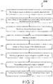
- FIG. 2 depicts a process flow 200 for an improved generator output voltage regulation in accordance with an embodiment.
- the process flow 200 can generally be implemented by and/or within the system 100.
- the process flow 200 is described with respect to an aircraft implementation; however, embodiments herein are not limited thereto.
- the process flow 200 begins at block 205, where the BPCU 110 receives a request to switch on a specific electrical load.
- the request can be received at a first time T1.
- the request can be, for example, from a hydraulic system of the aircraft to switch on an electric motor driven hydraulic pump that has inrush current.
- the inrush current can be large enough to cause a generator output voltage (e.g., the output voltage 165 of the generator 130) to exceed transient voltage limits.
- a generator output voltage e.g., the output voltage 165 of the generator 130
- transient voltage limits e.g., the output voltage 165 of the generator 130
- an application of the specific electrical load can cause the generator output voltage to dip from a nominal 115 Vrms to 70 Vrms, outside of the transient voltage limits.
- the BPCU 110 transmits communication signals indicating that the specific electrical load will be applied.
- the communication signals can be transmitted at a second time T2.
- the BPCU 110 can notify the voltage regulator 125 of the GCU 120 via the communication signals 161 that the specific electrical load is imminent.
- the GCU 120 receives communication signals. In this way, the GCU 120 receives a warning that the specific electrical load is imminent (e.g., receives a warning at 5 milliseconds that the specific electrical load is expected within the expected time TX).
- the GCU 120 alters the generator output voltage set point.
- the GCU 120 can utilize the voltage regulator 125 to alter the set point in response to the warning from the BPCU 110. For instance, the voltage regulator 125 can change the set point to a set voltage 165 volts.
- the GCU 120 can utilize the voltage regulator 125 to implement a change.
- the change can be a linear change (such as a linear decay of the set point), a nonlinear change, etc.
- the GCU 120 linearly decays the set voltage at 300 volts/sec until normal set voltage of 115 Vrms is reached (e.g., can occur in less than 200 milliseconds).
- the voltage regulator 125 can implement the linear decay in response to the changing the set point.
- the generator control unit 120 and voltage regulator 125 matches the generator output voltage to a specific voltage (e.g., based on the set point) to produce a matched generator output voltage.
- the voltage regulator 125 of the GCU 120 rapidly increases generator excitation current that causes the generator output voltage of the generator 130 to rapidly increase (e.g., to 165 Vrms). Note that this rapid increase will occur in response to the increased set point. Also note that the rapid increase can occur at a third time T3.
- increasing an excitation current to the generator can be performed without altering the set point, such as by altering the measured generator output voltage within the voltage regulator to cause an increase in the excitation current and the generator output voltage.
- the BPCU 110 transmits a command to close the contactor 140.
- the command can be received at a fourth time T4.
- the contactor 140 closes to apply the generator output voltage.
- the contactor 140 closes in response to the command of block 235.
- the contactor 140 can close at a fifth time T5, which can be in accordance with a delay between receiving the command and the actual closing.
- the set voltage can be approximately 160 volts, when the contactor closes and the voltage droops. Further, because the load application starts at a higher voltage, the low end of the voltage transient requirement is not violated.
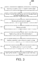
- FIG. 3 a process flow 300 for an improved generator output voltage regulation is shown in accordance with an embodiment.
- the process flow 300 can generally be implemented by and/or within the system 100.
- the process flow 300 is described with respect to an aircraft implementation; however, embodiments herein are not limited thereto.
- the process flow 300 begins at block 305, where the BPCU 110 receives a request to switch off a specific electrical load.
- the request can be received at a first time T1.
- the request can be, for example, from a hydraulic system of the aircraft to switch off an electric motor driven hydraulic pump that will result in a rapid increase in generator output voltage.
- the BPCU 110 transmits communication signals indicating that the specific electrical load will be removed.
- the communication signals can be transmitted at a second time T2.
- the BPCU 110 can notify the voltage regulator 125 of the GCU 120 via the communication signals 161 that the removal of the specific electrical load is imminent.
- the GCU 120 receives communication signals.
- the GCU 120 alters a set point and utilizes the voltage regulator 125 to implement a change.
- the change can be a linear change (such as a gradual increase of the set point), a nonlinear change, etc.
- the set point can be lowered to approximately 80 Vrms in anticipation of the specific electrical load removal. Further, the set point can then be gradually increased to 115 Vrms (such as over a time period of 200 milliseconds).
- the generator control unit 120 and voltage regulator 125 matches the generator output voltage to a specific voltage (e.g., based on the set point) to produce a matched generator output voltage.
- the voltage regulator 125 of the GCU 120 rapidly decreases generator excitation current that causes the generator output voltage of the generator 130 to rapidly decrease.
- decreasing an excitation current to the generator can be performed without altering the set point, such as by altering the measured generator output voltage within the voltage regulator to cause a decrease in the excitation current and the generator output voltage.
- the BPCU 110 transmits a command to open the contactor 140.
- the command can be received at a fourth time T4.
- the contactor 140 opens to remove the generator output voltage.
- specific timings and alterations can be calibrated with respect to applications and components within the aircraft.
- the system 100 can store and utilize multiple process flows for applying and/or removing specific electric loads based on the above process flows 200 and 300.
- the generator 130 can be driven by an auxiliary power unit or an aircraft turbine with respect to an increase throttle setting and/or pneumatic loads.
- the GCU 120 can communicate to a full authority digital engine/electronics control (FADEC) instead of or in conjunction with the BPCU 110.
- FADEC full authority digital engine/electronics control
- the GCU 120 can communicate to an engine controller connected to an engine and/or to the BPCU 110 through a communication bus can. In the latter case, like with the voltage regulator, the BPCU 110 can instruct the engine controller to produce more power in anticipation of a specific load application or less power in anticipation of a specific load removal.
- the set voltage can be elevated and held until the contactor 140 actually closes or until after a specific time limit is exceeded. Once load is applied and voltage reached (or is near a set voltage), the ramp rate back to 115 Vrms can be accelerated. The amount of the ramp rate can depend on the closed loop damping of the voltage regulation.
Landscapes
- Engineering & Computer Science (AREA)
- Power Engineering (AREA)
- Control Of Eletrric Generators (AREA)
Description
- In present aerospace power generation systems generator voltage regulation is accomplished using precise measurement of the generator output voltage and modulation of the generator excitation currents. This is typically done by a Generator Control Unit which incorporates a Voltage Regulator. When large electrical loads are applied to the generator output terminals the voltage will rapidly decrease until the Generator Control Unit/Voltage Regulator applies additional excitation current, recovering the generator output voltage to the desired level. In this implementation the Generator Control Unit/Voltage Regulator is reacting to the drooping generator output voltage, after the electric load is applied. Conversely, when a large electrical load is removed the generator the output voltage will increase and the Generator Control Unit/Voltage Regulator decreases generator excitation to decrease the generator output voltage back to desired levels. In this example the voltage regulator is again reacting to the increased generator output voltage. These systems typically have power quality requirements that specify the upper and lower transient voltage limits that are permitted. Voltage regulation can be improved if the Generator Control Unit/Voltage Regulator can anticipate or prepare for the application or removal of electrical loads and the transient voltage limits can be more easily met. Generator output regulation is discussed in
US 2002/097026 ,US 2017/033717 andUS 7,441,137 / - In accordance with one or more embodiments, a method of altering a generator output voltage in anticipation of a change with respect to a specific electrical load is provided as defined in claim 1.
- In accordance with an embodiment or the method embodiment above, implementing the change of the altered set point can include implementing a linear decay with respect to applying the matched generator output voltage.
- In accordance with an embodiment or any of the method embodiments above, implementing the change of the altered set point can include implementing a linear increase with respect to removing the matched generator output voltage.
- In accordance with an embodiment or any of the method embodiments above, a bus power control unit can receive a request to switch on the specific electrical load at a first time, and the specific electrical load can be required at an expected time.
- In accordance with an embodiment or any of the method embodiments above, the bus power control unit can transmit communication signals to the generator control unit, and the generator control unit can receive the communication signals identifying the specific electrical load at a second time, and the first and second time can occur before the expected time.
- In accordance with an embodiment or any of the method embodiments above, the communication signals from the bus power control unit can be responsive to a request to apply the specific electrical load.
- In accordance with an embodiment or any of the method embodiments above, the communication signals from the bus power control unit can be responsive to a request to remove the specific electrical load.
- In accordance with an embodiment or any of the method embodiments above, the bus power control unit can open and close the contactor in accordance with applying or removing the generator output voltage.
- In accordance with an embodiment or any of the method embodiments above, the generator control unit can receive a request to switch on the specific electrical load at a first time, and the specific electrical load can be required at an expected time.
- In accordance with an embodiment or any of the method embodiments above, the generator control unit can identify the specific electrical load at a second time, and the first and second time can occur before the expected time.
- In accordance with one or more embodiment embodiments, a system of altering a generator output voltage in anticipation of a change with respect to a specific electrical load is provided as defined in claim 9.
- In accordance with an embodiment or the system embodiment above, implementing the change of the altered set point can include implementing a linear decay with respect to applying the matched generator output voltage.
- In accordance with an embodiment or any of the system embodiments above, implementing the change of the altered set point can include implementing a linear increase with respect to removing the matched generator output voltage.
- In accordance with an embodiment or any of the system embodiments above, a bus power control unit can receive a request to switch on the specific electrical load at a first time, and the specific electrical load can be required at an expected time.
- In accordance with an embodiment or any of the system embodiments above, the bus power control unit can transmit communication signals to the generator control unit, the generator control unit receives the communication signals identifying the specific electrical load at a second time, and the first and second time can occur before the expected time.
- The following descriptions should not be considered limiting in any way. With reference to the accompanying drawings, like elements are numbered alike:
-
FIG. 1 depicts a system for an improved generator output voltage regulation in accordance with one or more embodiments; -
FIG. 2 depicts a process flow for an improved generator output voltage regulation in accordance with one or more embodiments; and -
FIG. 3 depicts a process flow for an improved generator output voltage regulation in accordance with one or more embodiments. - A detailed description of one or more embodiments of the disclosed apparatus and method are presented herein by way of exemplification and not limitation with reference to the Figures.
- Embodiments herein relate to a voltage regulator within a system that can increase a generator output voltage before large known loads are applied and decrease the generator output voltage before the large known loads are removed.
-
FIG. 1 depicts asystem 100 in accordance with one or more embodiments. Thesystem 100 comprises a bus power control unit (BPCU) 110 and generator control unit (GCU) 120 that includes avoltage regulator 125. The BPCU 110 and the GCU 120 can be processing units or components thereof that direct operations within thesystem 100. - The BPCU 110 and the GCU 120 can be implemented in hardware, software, and/or combination thereof, in combination with a memory (e.g., whether integrated or external to the processing units). The
BPCU 110 and the GCU 120 can utilize arithmetic logic and/or program instructions (stored on the memory) to direct the operations within thesystem 100. Examples of the BPCU 110 and the GCU 120 can include, but are not limited to, digital signal processors, microcontrollers, microprocessor, system on chip designs, network on chips, field-programmable arrays, and the like. BPCU 110 and GCU 120 could also be integrated together into one unit and still function as described. - The
system 100 further comprises agenerator 130, acontactor 140, a firstelectrical load 150, and one or more additional loads 155. Thegenerator 130 is an electro-mechanical device that converts mechanical energy to electrical energy for use in a circuit, such as thesystem 100. Examples of what propels thegenerator 130 can include, but are not limited to, aircraft engines, internal combustion engines, steam and gas turbines, and the like (e.g., a turbine, a gas engine, a diesel engine, a water turbine, etc. that produces shaft horsepower to drive the generator). Thecontactor 140 is an electrically controlled switch used for switching an electrical power circuit, such as the circuit between thegenerator 130 and theelectrical load 150. - According to one or more embodiments, the BPCU 110 and the GCU 120
transfer communication signals 161 via a communication bus, while the GCU 120 and thegenerator 130 transfer control signals 163 via control wires. Thegenerator 130 can further provide one ormore outputs 165 via electrical wiring. As shown, the one ormore outputs 165 can be provided to the firstelectrical load 150 via thecontactor 140 and/or the one or more additional loads 155. Note that the BPCU 110 based on thecontrol signal 167 can control thecontactor 140. - The
voltage regulator 125 of theGCU 120 is an electromechanical mechanism that regulates one or more AC or DC voltages of thegenerator 130. For example, theBPCU 110, which controls the electrical loads, can notify thevoltage regulator 125 via the communication signals 161 (or other method) that a specific load is imminent. Thevoltage regulator 125 can, in response, increase theoutput voltage 165 in anticipation of the specific load. Similarly, thevoltage regulator 125 can reduce theoutput voltage 165 in anticipation of the specific load removal. - In view of the
system 100, it can be appreciated that, for alternating current (AC) loads controlled by theBPCU 110, theGCU 120, and/or other line replaceable units, the technical effects and benefits can include improved AC voltage regulation via the voltage regulator 125 (which also leads to improved DC bus voltage regulation), along with increased voltage regulator gains and phase margins. Further, embodiments herein and the technical effects and benefits thereof are not limited to that function being performed by theBPCU 110, theGCU 120, and/or other line replaceable units, as preparing for load applications or removals by altering the generator output voltage in anticipation of load changes can be performed by alternative hardware, software, and/or combinations thereof. -
FIG. 2 depicts aprocess flow 200 for an improved generator output voltage regulation in accordance with an embodiment. Theprocess flow 200 can generally be implemented by and/or within thesystem 100. Theprocess flow 200 is described with respect to an aircraft implementation; however, embodiments herein are not limited thereto. - The
process flow 200 begins atblock 205, where the BPCU 110 receives a request to switch on a specific electrical load. The request can be received at a first time T1. In accordance with an embodiment, the first time T1 can be equal to zero (e.g., T1 = 0). - The request can be, for example, from a hydraulic system of the aircraft to switch on an electric motor driven hydraulic pump that has inrush current. The inrush current can be large enough to cause a generator output voltage (e.g., the
output voltage 165 of the generator 130) to exceed transient voltage limits. For example, an application of the specific electrical load can cause the generator output voltage to dip from a nominal 115 Vrms to 70 Vrms, outside of the transient voltage limits. - At
block 210, theBPCU 110 transmits communication signals indicating that the specific electrical load will be applied. The communication signals can be transmitted at a second time T2. In accordance with an embodiment, the second time T2 can be at 5 milliseconds (e.g., T2 = T1 + 5 milliseconds). - For instance, the
BPCU 110 can notify thevoltage regulator 125 of theGCU 120 via the communication signals 161 that the specific electrical load is imminent. In accordance with one or more embodiments, the communication signals indicate that the specific electrical load can be applied within an expected time TX (TX = T1 + X, where X can be 20 milliseconds). - At
block 215, theGCU 120 receives communication signals. In this way, theGCU 120 receives a warning that the specific electrical load is imminent (e.g., receives a warning at 5 milliseconds that the specific electrical load is expected within the expected time TX). Atblock 220, theGCU 120 alters the generator output voltage set point. TheGCU 120 can utilize thevoltage regulator 125 to alter the set point in response to the warning from theBPCU 110. For instance, thevoltage regulator 125 can change the set point to aset voltage 165 volts. Atblock 225, theGCU 120 can utilize thevoltage regulator 125 to implement a change. The change can be a linear change (such as a linear decay of the set point), a nonlinear change, etc. In accordance with one or more embodiments, theGCU 120 linearly decays the set voltage at 300 volts/sec until normal set voltage of 115 Vrms is reached (e.g., can occur in less than 200 milliseconds). Thevoltage regulator 125 can implement the linear decay in response to the changing the set point. - At
block 230, thegenerator control unit 120 andvoltage regulator 125 matches the generator output voltage to a specific voltage (e.g., based on the set point) to produce a matched generator output voltage. Thevoltage regulator 125 of theGCU 120 rapidly increases generator excitation current that causes the generator output voltage of thegenerator 130 to rapidly increase (e.g., to 165 Vrms). Note that this rapid increase will occur in response to the increased set point. Also note that the rapid increase can occur at a third time T3. In accordance with an embodiment, the third time T3 can be at 10 milliseconds (e.g., T3 = T1 + 10- milliseconds). In accordance with one or more embodiments, increasing an excitation current to the generator can be performed without altering the set point, such as by altering the measured generator output voltage within the voltage regulator to cause an increase in the excitation current and the generator output voltage. - At
block 235, theBPCU 110 transmits a command to close thecontactor 140. The command can be received at a fourth time T4. In accordance with an embodiment, the fourth time T4 can be at 15 milliseconds (e.g., T4 = T1 + 15 milliseconds). - At
block 240, thecontactor 140 closes to apply the generator output voltage. Thecontactor 140 closes in response to the command ofblock 235. Thecontactor 140 can close at a fifth time T5, which can be in accordance with a delay between receiving the command and the actual closing. In accordance with an embodiment, the fifth time T5 can be at 30 milliseconds (e.g., T5 = T1 + 30 milliseconds). Note that the set voltage can be approximately 160 volts, when the contactor closes and the voltage droops. Further, because the load application starts at a higher voltage, the low end of the voltage transient requirement is not violated. In addition, when the set voltage has returned to 115 Vrms at a sixth time T6, normal operation of thesystem 100 can resume. In accordance with an embodiment, the sixth time T6 can be at 200 milliseconds (e.g., T6 = T1 + 200 milliseconds) - In view of the above, improved regulation for a specific electrical load removal can be accomplished in complementary manner by lowering the set point. Turning now to
FIG. 3 , aprocess flow 300 for an improved generator output voltage regulation is shown in accordance with an embodiment. The process flow 300 can generally be implemented by and/or within thesystem 100. Theprocess flow 300 is described with respect to an aircraft implementation; however, embodiments herein are not limited thereto. - The
process flow 300 begins atblock 305, where theBPCU 110 receives a request to switch off a specific electrical load. The request can be received at a first time T1. In accordance with an embodiment, the first time T1 can be equal zero (e.g., T1 = 0). The request can be, for example, from a hydraulic system of the aircraft to switch off an electric motor driven hydraulic pump that will result in a rapid increase in generator output voltage. - At
block 310, theBPCU 110 transmits communication signals indicating that the specific electrical load will be removed. The communication signals can be transmitted at a second time T2. In accordance with an embodiment, the second time T2 can be at 5 milliseconds (e.g., T2 = T1 + 5 milliseconds). For instance, theBPCU 110 can notify thevoltage regulator 125 of theGCU 120 via the communication signals 161 that the removal of the specific electrical load is imminent. In accordance with one or more embodiments, the communication signals indicate that the specific electrical load can be removed within an expected time TX (TX = T1 + X, where X can be 20 milliseconds). - At
block 315, theGCU 120 receives communication signals. Atblocks GCU 120 alters a set point and utilizes thevoltage regulator 125 to implement a change. The change can be a linear change (such as a gradual increase of the set point), a nonlinear change, etc. In accordance with one or more embodiments, the set point can be lowered to approximately 80 Vrms in anticipation of the specific electrical load removal. Further, the set point can then be gradually increased to 115 Vrms (such as over a time period of 200 milliseconds). - At
block 330, thegenerator control unit 120 andvoltage regulator 125 matches the generator output voltage to a specific voltage (e.g., based on the set point) to produce a matched generator output voltage. Thevoltage regulator 125 of theGCU 120 rapidly decreases generator excitation current that causes the generator output voltage of thegenerator 130 to rapidly decrease. In accordance with one or more embodiments, decreasing an excitation current to the generator can be performed without altering the set point, such as by altering the measured generator output voltage within the voltage regulator to cause a decrease in the excitation current and the generator output voltage. - At
block 335, theBPCU 110 transmits a command to open thecontactor 140. The command can be received at a fourth time T4. In accordance with an embodiment, the fourth time T4 can be at 15 milliseconds (e.g., T4 = T1 + 15 milliseconds). Atblock 340, thecontactor 140 opens to remove the generator output voltage. - In accordance with one or more embodiments, specific timings and alterations can be calibrated with respect to applications and components within the aircraft. In this way, the
system 100 can store and utilize multiple process flows for applying and/or removing specific electric loads based on the above process flows 200 and 300. - In accordance with one or more embodiments, the
generator 130 can be driven by an auxiliary power unit or an aircraft turbine with respect to an increase throttle setting and/or pneumatic loads. Further, theGCU 120 can communicate to a full authority digital engine/electronics control (FADEC) instead of or in conjunction with theBPCU 110. Furthermore, theGCU 120 can communicate to an engine controller connected to an engine and/or to theBPCU 110 through a communication bus can. In the latter case, like with the voltage regulator, theBPCU 110 can instruct the engine controller to produce more power in anticipation of a specific load application or less power in anticipation of a specific load removal. - In accordance with one or more embodiments, the set voltage can be elevated and held until the
contactor 140 actually closes or until after a specific time limit is exceeded. Once load is applied and voltage reached (or is near a set voltage), the ramp rate back to 115 Vrms can be accelerated. The amount of the ramp rate can depend on the closed loop damping of the voltage regulation. - The term "about" is intended to include the degree of error associated with measurement of the particular quantity based upon the equipment available at the time of filing the application. For example, "about" can include a range of ± 8% or 5%, or 2% of a given value.
- The terminology used herein is for the purpose of describing particular embodiments only and is not intended to be limiting of the present disclosure. As used herein, the singular forms "a", "an" and "the" are intended to include the plural forms as well, unless the context clearly indicates otherwise. It will be further understood that the terms "comprises" and/or "comprising," when used in this specification, specify the presence of stated features, integers, steps, operations, elements, and/or components, but do not preclude the presence or addition of one or more other features, integers, steps, operations, element components, and/or groups thereof.
Claims (12)
- A method of altering a generator output voltage in anticipation of a change with respect to a specific electrical load, the method characterised by comprising:receiving, at a first time T1, by a bus power control unit BPCU (110), a request to switch on the specific electrical load comprising an inrush current to cause the generator output voltage to exceed a transient voltage limit;transmitting, at a second time T2, by the bus power control unit communication signals indicating that the specific electrical load will be applied within an expected time TX;receiving, at a generator control unit CGU (120), the communication signals indicating that the specific electrical load will be applied within an expected time TX;altering, by a voltage regulator (125) of the generator control unit (120), a set point to produce an altered set point in response to the communication signals;implementing, by the voltage regulator, a change of the altered set point;matching the generator output voltage to the altered set point to produce a matched generator output voltage;transmitting, by the bus power control unit in communication with the generator control unit, a command to close a contactor (140); andproviding the matched generator output voltage to the specific electrical load (150) based on a closing operation of the contactor, the closing operation being in accordance with a delay between receiving the command and an actual closing and mitigating the inrush current.
- The method of claim 1, wherein implementing the change of the altered set point includes implementing a linear increase with respect to removing the matched generator output voltage.
- The method of any preceding claim, wherein the bus power control unit (110) receives a request to switch on the specific electrical load at the first time.
- The method of claim 3,
wherein the generator control unit (120) receives the communication signals identifying the specific electrical load at the second time, and
wherein the first and second time occur before the expected time. - The method of claim 4, wherein the communication signals from the bus power control unit are responsive to a request to apply the specific electrical load.
- The method of claim 4, wherein the communication signals from the bus power control unit are responsive to a request to remove the specific electrical load.
- The method of claim 3, wherein the bus power control unit opens and closes the contactor (140) in accordance with applying or removing the generator output voltage.
- The method of claim of any preceding claim, wherein the generator control unit identifies the specific electrical load at a second time, and
wherein the first and second time occur before the expected time. - A system of altering a generator output voltage in anticipation of a change with respect to a specific electrical load, the system characterised by comprising:a generator control unit (120) comprising a voltage regulator (125);a generator (130) ;a bus power control unit (110) in communication with the generator control unit; anda contactor (140) ,wherein the bus power control unit is configured to receive, at a first time T1, a request to switch on the specific electrical load, the specific electrical load comprising an inrush current to cause the generator output voltage to exceed a transient voltage limit,wherein the bus power control unit is configured to transmit, at a second time T2, communication signals indicating that the specific electrical load will be applied within an expected time TX,wherein the generator control unit is configured to receive said communication signals indicating that the specific electrical load will be applied within an expected time TX;wherein the voltage regulator of the generator control unit is configured to alter a set point to produce an altered set point in response to the communication signals,wherein the voltage regulator of the generator control unit is configured to implement a change of the altered set point,wherein the generator is configured to match the generator output voltage to the altered set point to produce a matched generator output voltage;wherein the bus power control unit is configured to transmit a command to close the contactor; andwherein the generator is configured to provide the matched generator output voltage to a specific electrical load based on a closing operation of the contactor, the closing operation being in accordance with a delay between receiving the command and an actual closing and mitigating the inrush current.
- The system of claim 9, wherein implementing the change of the altered set point includes implementing a linear increase with respect to removing the matched generator output voltage.
- The system of claim 9 or 10, wherein the bus power control unit receives a request to switch on the specific electrical load at the first time.
- The system of claim 11,wherein the generator control unit receives the communication signals identifying the specific electrical load at the second time, and
wherein the first and second time occur before the expected time.
Applications Claiming Priority (1)
| Application Number | Priority Date | Filing Date | Title |
|---|---|---|---|
| US15/581,059 US20180316295A1 (en) | 2017-04-28 | 2017-04-28 | Generator output voltage regulation |
Publications (2)
| Publication Number | Publication Date |
|---|---|
| EP3396849A1 EP3396849A1 (en) | 2018-10-31 |
| EP3396849B1 true EP3396849B1 (en) | 2021-03-17 |
Family
ID=62091760
Family Applications (1)
| Application Number | Title | Priority Date | Filing Date |
|---|---|---|---|
| EP18170106.1A Active EP3396849B1 (en) | 2017-04-28 | 2018-04-30 | Improved generator output voltage regulation |
Country Status (2)
| Country | Link |
|---|---|
| US (1) | US20180316295A1 (en) |
| EP (1) | EP3396849B1 (en) |
Families Citing this family (3)
| Publication number | Priority date | Publication date | Assignee | Title |
|---|---|---|---|---|
| US10263552B2 (en) * | 2017-08-08 | 2019-04-16 | Rolls-Royce North American Technologies Inc. | Anticipatory control using output shaft speed |
| US11770084B2 (en) | 2021-10-22 | 2023-09-26 | Honeywell International Inc. | Voltage regulation of high voltage direct current systems |
| US12328028B2 (en) | 2022-08-25 | 2025-06-10 | Honeywell International Inc. | Energy management of hybrid electrical systems |
Family Cites Families (7)
| Publication number | Priority date | Publication date | Assignee | Title |
|---|---|---|---|---|
| US6624618B2 (en) * | 2001-01-25 | 2003-09-23 | Ford Global Technologies, Llc | System and method for vehicle voltage regulation |
| US7441137B1 (en) * | 2005-07-25 | 2008-10-21 | Nvidia Corporation | Voltage regulator with internal controls for adjusting output based on feed-forward load information |
| US8400001B2 (en) * | 2010-01-15 | 2013-03-19 | Kohler Co. | Adaptive control of an electrical generator set based on load magnitude |
| CA2831665C (en) * | 2011-03-29 | 2016-05-31 | Innovus Power, Inc. | Generator |
| FR2979767B1 (en) * | 2011-09-01 | 2015-04-03 | Leroy Somer Moteurs | METHOD FOR REGULATING AN ELECTROGEN GROUP |
| FR2979765B1 (en) * | 2011-09-01 | 2015-06-26 | Leroy Somer Moteurs | METHOD FOR REGULATING AN ELECTROGEN GROUP |
| US10707788B2 (en) * | 2015-07-28 | 2020-07-07 | Ford Global Technologies, Llc | Vehicle transient voltage control |
-
2017
- 2017-04-28 US US15/581,059 patent/US20180316295A1/en not_active Abandoned
-
2018
- 2018-04-30 EP EP18170106.1A patent/EP3396849B1/en active Active
Non-Patent Citations (1)
| Title |
|---|
| None * |
Also Published As
| Publication number | Publication date |
|---|---|
| EP3396849A1 (en) | 2018-10-31 |
| US20180316295A1 (en) | 2018-11-01 |
Similar Documents
| Publication | Publication Date | Title |
|---|---|---|
| US7448220B2 (en) | Torque control for starting system | |
| KR102265943B1 (en) | Method and system for more reliable starting of a turbo machine | |
| RU2222863C2 (en) | Power supply system for motor-driven loads | |
| EP2465193B1 (en) | A protection arrangement of an electric power system | |
| US9365210B2 (en) | Method and arrangement in a hybrid vehicle | |
| EP2028758A1 (en) | Engine having power bus fault short circuit control with a disconnection switch | |
| JP2006296200A (en) | Wind turbine operating method and wind turbine | |
| EP3396849A1 (en) | Improved generator output voltage regulation | |
| US8305777B2 (en) | Control device for rectifier stations in a high-voltage DC transmission system | |
| US9988135B2 (en) | System for controlling an electrical power system | |
| JPS61500763A (en) | Combination startup/power generation system and method | |
| US20190225348A1 (en) | A method and a system for powering an electrical load in an aircraft | |
| US20090134845A1 (en) | Device for Controlling an Electricity Generator Set | |
| SE469758B (en) | PROCEDURES FOR CONTROL OF EFFICIENCY GENERATED BY A GAS TURBIN AND DEVICE FOR IMPLEMENTATION OF THE PROCEDURE | |
| CN202560368U (en) | Generating set | |
| US4791309A (en) | Electrical control systems | |
| EP2045910A2 (en) | Starter/generator system with control to address a voltage rise | |
| US20160126740A1 (en) | Power plant | |
| SE519419C2 (en) | Method and device for charging a battery | |
| EP1626492B1 (en) | Method in frequency converter provided with voltage intermediate circuit, and frequency converter | |
| EP2061148B1 (en) | Protection of variable frequency power systems from excessive peak electrical potentials | |
| KR101506530B1 (en) | The device and the method for ramp-up of generator output voltage | |
| JP2009047087A (en) | Pumped-storage power generator and control method thereof | |
| AU2021107650B4 (en) | System configured to supply electrical power to an electric submersible pump | |
| US12525798B2 (en) | Process for controlling isolated microgrids based on power-based control and modified Volt-VAr function methods |
Legal Events
| Date | Code | Title | Description |
|---|---|---|---|
| PUAI | Public reference made under article 153(3) epc to a published international application that has entered the european phase |
Free format text: ORIGINAL CODE: 0009012 |
|
| STAA | Information on the status of an ep patent application or granted ep patent |
Free format text: STATUS: THE APPLICATION HAS BEEN PUBLISHED |
|
| AK | Designated contracting states |
Kind code of ref document: A1 Designated state(s): AL AT BE BG CH CY CZ DE DK EE ES FI FR GB GR HR HU IE IS IT LI LT LU LV MC MK MT NL NO PL PT RO RS SE SI SK SM TR |
|
| AX | Request for extension of the european patent |
Extension state: BA ME |
|
| STAA | Information on the status of an ep patent application or granted ep patent |
Free format text: STATUS: REQUEST FOR EXAMINATION WAS MADE |
|
| 17P | Request for examination filed |
Effective date: 20190430 |
|
| RBV | Designated contracting states (corrected) |
Designated state(s): AL AT BE BG CH CY CZ DE DK EE ES FI FR GB GR HR HU IE IS IT LI LT LU LV MC MK MT NL NO PL PT RO RS SE SI SK SM TR |
|
| STAA | Information on the status of an ep patent application or granted ep patent |
Free format text: STATUS: EXAMINATION IS IN PROGRESS |
|
| 17Q | First examination report despatched |
Effective date: 20191211 |
|
| GRAP | Despatch of communication of intention to grant a patent |
Free format text: ORIGINAL CODE: EPIDOSNIGR1 |
|
| STAA | Information on the status of an ep patent application or granted ep patent |
Free format text: STATUS: GRANT OF PATENT IS INTENDED |
|
| INTG | Intention to grant announced |
Effective date: 20201015 |
|
| GRAS | Grant fee paid |
Free format text: ORIGINAL CODE: EPIDOSNIGR3 |
|
| GRAA | (expected) grant |
Free format text: ORIGINAL CODE: 0009210 |
|
| STAA | Information on the status of an ep patent application or granted ep patent |
Free format text: STATUS: THE PATENT HAS BEEN GRANTED |
|
| AK | Designated contracting states |
Kind code of ref document: B1 Designated state(s): AL AT BE BG CH CY CZ DE DK EE ES FI FR GB GR HR HU IE IS IT LI LT LU LV MC MK MT NL NO PL PT RO RS SE SI SK SM TR |
|
| REG | Reference to a national code |
Ref country code: GB Ref legal event code: FG4D |
|
| REG | Reference to a national code |
Ref country code: CH Ref legal event code: EP |
|
| REG | Reference to a national code |
Ref country code: DE Ref legal event code: R096 Ref document number: 602018013916 Country of ref document: DE |
|
| REG | Reference to a national code |
Ref country code: IE Ref legal event code: FG4D |
|
| REG | Reference to a national code |
Ref country code: AT Ref legal event code: REF Ref document number: 1373182 Country of ref document: AT Kind code of ref document: T Effective date: 20210415 |
|
| REG | Reference to a national code |
Ref country code: LT Ref legal event code: MG9D |
|
| PG25 | Lapsed in a contracting state [announced via postgrant information from national office to epo] |
Ref country code: NO Free format text: LAPSE BECAUSE OF FAILURE TO SUBMIT A TRANSLATION OF THE DESCRIPTION OR TO PAY THE FEE WITHIN THE PRESCRIBED TIME-LIMIT Effective date: 20210617 Ref country code: HR Free format text: LAPSE BECAUSE OF FAILURE TO SUBMIT A TRANSLATION OF THE DESCRIPTION OR TO PAY THE FEE WITHIN THE PRESCRIBED TIME-LIMIT Effective date: 20210317 Ref country code: FI Free format text: LAPSE BECAUSE OF FAILURE TO SUBMIT A TRANSLATION OF THE DESCRIPTION OR TO PAY THE FEE WITHIN THE PRESCRIBED TIME-LIMIT Effective date: 20210317 Ref country code: GR Free format text: LAPSE BECAUSE OF FAILURE TO SUBMIT A TRANSLATION OF THE DESCRIPTION OR TO PAY THE FEE WITHIN THE PRESCRIBED TIME-LIMIT Effective date: 20210618 Ref country code: BG Free format text: LAPSE BECAUSE OF FAILURE TO SUBMIT A TRANSLATION OF THE DESCRIPTION OR TO PAY THE FEE WITHIN THE PRESCRIBED TIME-LIMIT Effective date: 20210617 |
|
| REG | Reference to a national code |
Ref country code: AT Ref legal event code: MK05 Ref document number: 1373182 Country of ref document: AT Kind code of ref document: T Effective date: 20210317 |
|
| REG | Reference to a national code |
Ref country code: NL Ref legal event code: MP Effective date: 20210317 |
|
| PG25 | Lapsed in a contracting state [announced via postgrant information from national office to epo] |
Ref country code: RS Free format text: LAPSE BECAUSE OF FAILURE TO SUBMIT A TRANSLATION OF THE DESCRIPTION OR TO PAY THE FEE WITHIN THE PRESCRIBED TIME-LIMIT Effective date: 20210317 Ref country code: LV Free format text: LAPSE BECAUSE OF FAILURE TO SUBMIT A TRANSLATION OF THE DESCRIPTION OR TO PAY THE FEE WITHIN THE PRESCRIBED TIME-LIMIT Effective date: 20210317 Ref country code: SE Free format text: LAPSE BECAUSE OF FAILURE TO SUBMIT A TRANSLATION OF THE DESCRIPTION OR TO PAY THE FEE WITHIN THE PRESCRIBED TIME-LIMIT Effective date: 20210317 |
|
| PG25 | Lapsed in a contracting state [announced via postgrant information from national office to epo] |
Ref country code: NL Free format text: LAPSE BECAUSE OF FAILURE TO SUBMIT A TRANSLATION OF THE DESCRIPTION OR TO PAY THE FEE WITHIN THE PRESCRIBED TIME-LIMIT Effective date: 20210317 |
|
| PG25 | Lapsed in a contracting state [announced via postgrant information from national office to epo] |
Ref country code: SM Free format text: LAPSE BECAUSE OF FAILURE TO SUBMIT A TRANSLATION OF THE DESCRIPTION OR TO PAY THE FEE WITHIN THE PRESCRIBED TIME-LIMIT Effective date: 20210317 Ref country code: AT Free format text: LAPSE BECAUSE OF FAILURE TO SUBMIT A TRANSLATION OF THE DESCRIPTION OR TO PAY THE FEE WITHIN THE PRESCRIBED TIME-LIMIT Effective date: 20210317 Ref country code: EE Free format text: LAPSE BECAUSE OF FAILURE TO SUBMIT A TRANSLATION OF THE DESCRIPTION OR TO PAY THE FEE WITHIN THE PRESCRIBED TIME-LIMIT Effective date: 20210317 Ref country code: CZ Free format text: LAPSE BECAUSE OF FAILURE TO SUBMIT A TRANSLATION OF THE DESCRIPTION OR TO PAY THE FEE WITHIN THE PRESCRIBED TIME-LIMIT Effective date: 20210317 Ref country code: LT Free format text: LAPSE BECAUSE OF FAILURE TO SUBMIT A TRANSLATION OF THE DESCRIPTION OR TO PAY THE FEE WITHIN THE PRESCRIBED TIME-LIMIT Effective date: 20210317 |
|
| PG25 | Lapsed in a contracting state [announced via postgrant information from national office to epo] |
Ref country code: PT Free format text: LAPSE BECAUSE OF FAILURE TO SUBMIT A TRANSLATION OF THE DESCRIPTION OR TO PAY THE FEE WITHIN THE PRESCRIBED TIME-LIMIT Effective date: 20210719 Ref country code: PL Free format text: LAPSE BECAUSE OF FAILURE TO SUBMIT A TRANSLATION OF THE DESCRIPTION OR TO PAY THE FEE WITHIN THE PRESCRIBED TIME-LIMIT Effective date: 20210317 Ref country code: SK Free format text: LAPSE BECAUSE OF FAILURE TO SUBMIT A TRANSLATION OF THE DESCRIPTION OR TO PAY THE FEE WITHIN THE PRESCRIBED TIME-LIMIT Effective date: 20210317 Ref country code: RO Free format text: LAPSE BECAUSE OF FAILURE TO SUBMIT A TRANSLATION OF THE DESCRIPTION OR TO PAY THE FEE WITHIN THE PRESCRIBED TIME-LIMIT Effective date: 20210317 Ref country code: IS Free format text: LAPSE BECAUSE OF FAILURE TO SUBMIT A TRANSLATION OF THE DESCRIPTION OR TO PAY THE FEE WITHIN THE PRESCRIBED TIME-LIMIT Effective date: 20210717 |
|
| REG | Reference to a national code |
Ref country code: DE Ref legal event code: R097 Ref document number: 602018013916 Country of ref document: DE |
|
| PG25 | Lapsed in a contracting state [announced via postgrant information from national office to epo] |
Ref country code: LU Free format text: LAPSE BECAUSE OF NON-PAYMENT OF DUE FEES Effective date: 20210430 |
|
| REG | Reference to a national code |
Ref country code: BE Ref legal event code: MM Effective date: 20210430 |
|
| PLBE | No opposition filed within time limit |
Free format text: ORIGINAL CODE: 0009261 |
|
| STAA | Information on the status of an ep patent application or granted ep patent |
Free format text: STATUS: NO OPPOSITION FILED WITHIN TIME LIMIT |
|
| PG25 | Lapsed in a contracting state [announced via postgrant information from national office to epo] |
Ref country code: ES Free format text: LAPSE BECAUSE OF FAILURE TO SUBMIT A TRANSLATION OF THE DESCRIPTION OR TO PAY THE FEE WITHIN THE PRESCRIBED TIME-LIMIT Effective date: 20210317 Ref country code: AL Free format text: LAPSE BECAUSE OF FAILURE TO SUBMIT A TRANSLATION OF THE DESCRIPTION OR TO PAY THE FEE WITHIN THE PRESCRIBED TIME-LIMIT Effective date: 20210317 Ref country code: CH Free format text: LAPSE BECAUSE OF NON-PAYMENT OF DUE FEES Effective date: 20210430 Ref country code: DK Free format text: LAPSE BECAUSE OF FAILURE TO SUBMIT A TRANSLATION OF THE DESCRIPTION OR TO PAY THE FEE WITHIN THE PRESCRIBED TIME-LIMIT Effective date: 20210317 Ref country code: MC Free format text: LAPSE BECAUSE OF FAILURE TO SUBMIT A TRANSLATION OF THE DESCRIPTION OR TO PAY THE FEE WITHIN THE PRESCRIBED TIME-LIMIT Effective date: 20210317 Ref country code: LI Free format text: LAPSE BECAUSE OF NON-PAYMENT OF DUE FEES Effective date: 20210430 |
|
| 26N | No opposition filed |
Effective date: 20211220 |
|
| PG25 | Lapsed in a contracting state [announced via postgrant information from national office to epo] |
Ref country code: SI Free format text: LAPSE BECAUSE OF FAILURE TO SUBMIT A TRANSLATION OF THE DESCRIPTION OR TO PAY THE FEE WITHIN THE PRESCRIBED TIME-LIMIT Effective date: 20210317 |
|
| PG25 | Lapsed in a contracting state [announced via postgrant information from national office to epo] |
Ref country code: IT Free format text: LAPSE BECAUSE OF FAILURE TO SUBMIT A TRANSLATION OF THE DESCRIPTION OR TO PAY THE FEE WITHIN THE PRESCRIBED TIME-LIMIT Effective date: 20210317 Ref country code: IE Free format text: LAPSE BECAUSE OF NON-PAYMENT OF DUE FEES Effective date: 20210430 |
|
| PG25 | Lapsed in a contracting state [announced via postgrant information from national office to epo] |
Ref country code: IS Free format text: LAPSE BECAUSE OF FAILURE TO SUBMIT A TRANSLATION OF THE DESCRIPTION OR TO PAY THE FEE WITHIN THE PRESCRIBED TIME-LIMIT Effective date: 20210717 |
|
| PG25 | Lapsed in a contracting state [announced via postgrant information from national office to epo] |
Ref country code: BE Free format text: LAPSE BECAUSE OF NON-PAYMENT OF DUE FEES Effective date: 20210430 |
|
| P01 | Opt-out of the competence of the unified patent court (upc) registered |
Effective date: 20230522 |
|
| PG25 | Lapsed in a contracting state [announced via postgrant information from national office to epo] |
Ref country code: CY Free format text: LAPSE BECAUSE OF FAILURE TO SUBMIT A TRANSLATION OF THE DESCRIPTION OR TO PAY THE FEE WITHIN THE PRESCRIBED TIME-LIMIT Effective date: 20210317 |
|
| PG25 | Lapsed in a contracting state [announced via postgrant information from national office to epo] |
Ref country code: HU Free format text: LAPSE BECAUSE OF FAILURE TO SUBMIT A TRANSLATION OF THE DESCRIPTION OR TO PAY THE FEE WITHIN THE PRESCRIBED TIME-LIMIT; INVALID AB INITIO Effective date: 20180430 |
|
| PG25 | Lapsed in a contracting state [announced via postgrant information from national office to epo] |
Ref country code: MK Free format text: LAPSE BECAUSE OF FAILURE TO SUBMIT A TRANSLATION OF THE DESCRIPTION OR TO PAY THE FEE WITHIN THE PRESCRIBED TIME-LIMIT Effective date: 20210317 |
|
| PG25 | Lapsed in a contracting state [announced via postgrant information from national office to epo] |
Ref country code: MT Free format text: LAPSE BECAUSE OF FAILURE TO SUBMIT A TRANSLATION OF THE DESCRIPTION OR TO PAY THE FEE WITHIN THE PRESCRIBED TIME-LIMIT Effective date: 20210317 |
|
| PGFP | Annual fee paid to national office [announced via postgrant information from national office to epo] |
Ref country code: DE Payment date: 20250319 Year of fee payment: 8 |
|
| PG25 | Lapsed in a contracting state [announced via postgrant information from national office to epo] |
Ref country code: TR Free format text: LAPSE BECAUSE OF FAILURE TO SUBMIT A TRANSLATION OF THE DESCRIPTION OR TO PAY THE FEE WITHIN THE PRESCRIBED TIME-LIMIT Effective date: 20210317 |
|
| PGFP | Annual fee paid to national office [announced via postgrant information from national office to epo] |
Ref country code: GB Payment date: 20260319 Year of fee payment: 9 |
|
| PGFP | Annual fee paid to national office [announced via postgrant information from national office to epo] |
Ref country code: FR Payment date: 20260319 Year of fee payment: 9 |