EP3396790A1 - Connector assembly for safety systems - Google Patents
Connector assembly for safety systems Download PDFInfo
- Publication number
- EP3396790A1 EP3396790A1 EP17168508.4A EP17168508A EP3396790A1 EP 3396790 A1 EP3396790 A1 EP 3396790A1 EP 17168508 A EP17168508 A EP 17168508A EP 3396790 A1 EP3396790 A1 EP 3396790A1
- Authority
- EP
- European Patent Office
- Prior art keywords
- connector
- along
- axis
- mating
- connector assembly
- Prior art date
- Legal status (The legal status is an assumption and is not a legal conclusion. Google has not performed a legal analysis and makes no representation as to the accuracy of the status listed.)
- Withdrawn
Links
- 230000013011 mating Effects 0.000 claims abstract description 70
- 230000008878 coupling Effects 0.000 description 2
- 238000010168 coupling process Methods 0.000 description 2
- 238000005859 coupling reaction Methods 0.000 description 2
- 229910000859 α-Fe Inorganic materials 0.000 description 2
- 230000001419 dependent effect Effects 0.000 description 1
- 238000009429 electrical wiring Methods 0.000 description 1
- 238000000034 method Methods 0.000 description 1
Images




Classifications
-
- H—ELECTRICITY
- H01—ELECTRIC ELEMENTS
- H01R—ELECTRICALLY-CONDUCTIVE CONNECTIONS; STRUCTURAL ASSOCIATIONS OF A PLURALITY OF MUTUALLY-INSULATED ELECTRICAL CONNECTING ELEMENTS; COUPLING DEVICES; CURRENT COLLECTORS
- H01R24/00—Two-part coupling devices, or either of their cooperating parts, characterised by their overall structure
- H01R24/005—Two-part coupling devices, or either of their cooperating parts, characterised by their overall structure requiring successive relative motions to complete the coupling, e.g. bayonet type
-
- H—ELECTRICITY
- H01—ELECTRIC ELEMENTS
- H01R—ELECTRICALLY-CONDUCTIVE CONNECTIONS; STRUCTURAL ASSOCIATIONS OF A PLURALITY OF MUTUALLY-INSULATED ELECTRICAL CONNECTING ELEMENTS; COUPLING DEVICES; CURRENT COLLECTORS
- H01R13/00—Details of coupling devices of the kinds covered by groups H01R12/70 or H01R24/00 - H01R33/00
- H01R13/62—Means for facilitating engagement or disengagement of coupling parts or for holding them in engagement
- H01R13/627—Snap or like fastening
- H01R13/6271—Latching means integral with the housing
- H01R13/6273—Latching means integral with the housing comprising two latching arms
-
- H—ELECTRICITY
- H01—ELECTRIC ELEMENTS
- H01R—ELECTRICALLY-CONDUCTIVE CONNECTIONS; STRUCTURAL ASSOCIATIONS OF A PLURALITY OF MUTUALLY-INSULATED ELECTRICAL CONNECTING ELEMENTS; COUPLING DEVICES; CURRENT COLLECTORS
- H01R13/00—Details of coupling devices of the kinds covered by groups H01R12/70 or H01R24/00 - H01R33/00
- H01R13/02—Contact members
-
- H—ELECTRICITY
- H01—ELECTRIC ELEMENTS
- H01R—ELECTRICALLY-CONDUCTIVE CONNECTIONS; STRUCTURAL ASSOCIATIONS OF A PLURALITY OF MUTUALLY-INSULATED ELECTRICAL CONNECTING ELEMENTS; COUPLING DEVICES; CURRENT COLLECTORS
- H01R13/00—Details of coupling devices of the kinds covered by groups H01R12/70 or H01R24/00 - H01R33/00
- H01R13/46—Bases; Cases
- H01R13/502—Bases; Cases composed of different pieces
- H01R13/5025—Bases; Cases composed of different pieces one or more pieces being of resilient material
-
- H—ELECTRICITY
- H01—ELECTRIC ELEMENTS
- H01R—ELECTRICALLY-CONDUCTIVE CONNECTIONS; STRUCTURAL ASSOCIATIONS OF A PLURALITY OF MUTUALLY-INSULATED ELECTRICAL CONNECTING ELEMENTS; COUPLING DEVICES; CURRENT COLLECTORS
- H01R13/00—Details of coupling devices of the kinds covered by groups H01R12/70 or H01R24/00 - H01R33/00
- H01R13/62—Means for facilitating engagement or disengagement of coupling parts or for holding them in engagement
- H01R13/629—Additional means for facilitating engagement or disengagement of coupling parts, e.g. aligning or guiding means, levers, gas pressure electrical locking indicators, manufacturing tolerances
-
- H—ELECTRICITY
- H01—ELECTRIC ELEMENTS
- H01R—ELECTRICALLY-CONDUCTIVE CONNECTIONS; STRUCTURAL ASSOCIATIONS OF A PLURALITY OF MUTUALLY-INSULATED ELECTRICAL CONNECTING ELEMENTS; COUPLING DEVICES; CURRENT COLLECTORS
- H01R13/00—Details of coupling devices of the kinds covered by groups H01R12/70 or H01R24/00 - H01R33/00
- H01R13/62—Means for facilitating engagement or disengagement of coupling parts or for holding them in engagement
- H01R13/639—Additional means for holding or locking coupling parts together, after engagement, e.g. separate keylock, retainer strap
-
- H—ELECTRICITY
- H01—ELECTRIC ELEMENTS
- H01R—ELECTRICALLY-CONDUCTIVE CONNECTIONS; STRUCTURAL ASSOCIATIONS OF A PLURALITY OF MUTUALLY-INSULATED ELECTRICAL CONNECTING ELEMENTS; COUPLING DEVICES; CURRENT COLLECTORS
- H01R13/00—Details of coupling devices of the kinds covered by groups H01R12/70 or H01R24/00 - H01R33/00
- H01R13/64—Means for preventing incorrect coupling
- H01R13/641—Means for preventing incorrect coupling by indicating incorrect coupling; by indicating correct or full engagement
-
- H—ELECTRICITY
- H01—ELECTRIC ELEMENTS
- H01R—ELECTRICALLY-CONDUCTIVE CONNECTIONS; STRUCTURAL ASSOCIATIONS OF A PLURALITY OF MUTUALLY-INSULATED ELECTRICAL CONNECTING ELEMENTS; COUPLING DEVICES; CURRENT COLLECTORS
- H01R13/00—Details of coupling devices of the kinds covered by groups H01R12/70 or H01R24/00 - H01R33/00
- H01R13/62—Means for facilitating engagement or disengagement of coupling parts or for holding them in engagement
- H01R13/629—Additional means for facilitating engagement or disengagement of coupling parts, e.g. aligning or guiding means, levers, gas pressure electrical locking indicators, manufacturing tolerances
- H01R13/631—Additional means for facilitating engagement or disengagement of coupling parts, e.g. aligning or guiding means, levers, gas pressure electrical locking indicators, manufacturing tolerances for engagement only
-
- H—ELECTRICITY
- H01—ELECTRIC ELEMENTS
- H01R—ELECTRICALLY-CONDUCTIVE CONNECTIONS; STRUCTURAL ASSOCIATIONS OF A PLURALITY OF MUTUALLY-INSULATED ELECTRICAL CONNECTING ELEMENTS; COUPLING DEVICES; CURRENT COLLECTORS
- H01R2103/00—Two poles
-
- H—ELECTRICITY
- H01—ELECTRIC ELEMENTS
- H01R—ELECTRICALLY-CONDUCTIVE CONNECTIONS; STRUCTURAL ASSOCIATIONS OF A PLURALITY OF MUTUALLY-INSULATED ELECTRICAL CONNECTING ELEMENTS; COUPLING DEVICES; CURRENT COLLECTORS
- H01R2201/00—Connectors or connections adapted for particular applications
- H01R2201/26—Connectors or connections adapted for particular applications for vehicles
-
- H—ELECTRICITY
- H01—ELECTRIC ELEMENTS
- H01R—ELECTRICALLY-CONDUCTIVE CONNECTIONS; STRUCTURAL ASSOCIATIONS OF A PLURALITY OF MUTUALLY-INSULATED ELECTRICAL CONNECTING ELEMENTS; COUPLING DEVICES; CURRENT COLLECTORS
- H01R24/00—Two-part coupling devices, or either of their cooperating parts, characterised by their overall structure
- H01R24/28—Coupling parts carrying pins, blades or analogous contacts and secured only to wire or cable
Definitions
- the present invention relates to a connector assembly, in particular for airbag restraint systems.
- the connector assembly comprises a connector housing comprising a connector position assurance device and a counter connector.
- the connector position assurance device is assigned to the connector housing so that it is movable relative to the connector housing from an open position to a closed position.
- the safe coupling of connectors is of high importance.
- the connectors used for the connection of an airbag to its ignition base have to be provided with reliable safety systems.
- locking means are used to guarantee a safe mechanical coupling.
- This connector has a secondary lock and is used in many vehicles. However, despite its miniaturization, this connector has a certain size. The plug protrudes from the mating connector in the plugged state, which can lead to problems during assembly in very confined spaces. Since the miniaturization now produces plug-in systems that are no longer manageable and larger components, such as ferrite bodies, must also be accommodated, another way must be found to solve the problems.
- the object of the invention is to provide an electrical connector assembly for an airbag ignition device, which is easy to handle during assembly, provides a secure plug-in connection and is suitable for narrow building spaces.
- the electrical connector assembly provides a flat connector structure that can be used in narrow environments.
- the first connector and the second connector are small concerning the mating axis. Furthermore the first connector is preferable fully received in the second connector. That's why the size in mating direction is dependent only on the second connector.
- the first locking means is a protrusion protruding outwards from the elongated housing, along the transverse axis. Because the protrusion protrudes along the transverse axis it doesn't increase space requirement along the mating axis.
- the protrusion can be designed to extend a distance along the longitudinal axis to be more robust.
- the protrusion is arranged on a free end of a flexible arm, wherein the flexible arm extends from the elongated housing along the mating axis towards the second connector.
- the flexible arm provides flexibility in the way that the protrusion can be displaced inwardly to the elongated housing by the shroud, while mating. Because the flexible arm extends towards the second connector the protrusion comes in contact with the shroud in an early state of mating, the flexible arm, displaced inwardly, is protected from damages.
- the flexible arm extends along mating axis at the same distance as the elongated housing.
- the flexible arm should be as long as possible but not increase the size of the first connector.
- third locking means is an edge defined by a recess in an inner wall of the shroud.
- An easy and cheap way to provide the edge in the shroud is to make a recess. If necessary also a cavity can be provided in the shroud.
- the second locking means is a connector position assurance device attached to the elongated housing, wherein the connector position assurance device is movable along the longitudinal axis between an open position and a blocked position, when the connector assembly is mated.
- the second locking means prevents the connector assembly from accidentally disconnecting.
- the second locking means is operable along the longitudinal axis and needs no additional space, neither along the transversal axis nor along the mating axis.
- the connector position assurance device comprises main part aligned along the transversal axis.
- the main part has some functions. It works with handle for the operator while mating the connectors, especially while locking the second locking means. Furthermore the main part works as start point for protrusions needed by the connector position assurance device. Finally the main part defines the wall of the elongated housing in a finally assembled state.
- the connector position assurance device comprises a bar shaped portion protruding from the main part along the longitudinal axis towards the elongated housing and wherein the elongated housing comprises a guide cavity aligned along the longitudinal axis and wherein the bar shaped portion is movable inside the guide cavity along the longitudinal axis , when the connector assembly is mated.
- a portion of the guide cavity surrounding wall is defined by the flexible arm. While mating the flexible arm is bent, at least partly, into the guide cavity. When finally mated the flexible arm is relaxed again, whereby the protrusion protrudes in a predefined opening.
- the flexible arm defines a portion of the wall, surrounding the guide cavity.
- the guide cavity is ready to receive the bar shaped portion.
- the bar shaped portion fills the guide cavity when in the closed position thereby preventing movement of the flexible arm. Without movement of the flexible arm the protrusion is held securely in the predefined opening and locks the first and the second connectors.
- the bar shaped portion and the guide cavity have a rectangular cross section.
- a rectangular cross section provides good guiding abilities.
- the elongated housing comprises openings for guide through electrical wires, wherein the connector position assurance device is attached opposite to the openings at the elongated housing, whereby the connector position assurance device is moved towards the openings while moving from the open position to the blocked position.
- This arrangement allows, while manually assembling the connectors, to hold and guide the first connector to the correct position using a first hand by holding the electrical wires. In the correct position the connectors can be plugged to and locked by a second hand. The electrical wires do not disturb the operating of the position assurance device.
- the first connector comprises terminals and the second connector comprises contact elements, wherein in a plane, spanned by the longitudinal axis and transversal axis, at least, a portion of the terminals and a portion of the contact elements and a portion of the bar shaped portion and a portion of the flexible arm, is present in one point along the mating axis.
- This design provides a robust connector.
- the contact elements are surrounded by the locking means especially in the area where they make contact. This promises high reliability of the electrical connection.
- the first connector comprises terminals and the second connector comprises contact elements, wherein contacting points between the terminals and the contact elements and a portion of the bar shaped portion and a portion of the flexible arm is arranged in a row along the transversal axis.
- This design provides also a robust connector.
- the contact elements are adjacent to the locking means. This arrangement of contact elements and locking means promises high reliability of the electrical connection.
- the connector position assurance device comprises a safety arm to block the connector position assurance device in an unmated condition.
- the safety arm protruding from the main part along the longitudinal axis towards the elongated housing comprises an outwardly sloped safety surface that is arranged on the safety arm.
- the second connector comprises a post protruding along the mating axis, having an inwardly sloped release surface and after mating the sloped safety surface and the sloped release surface cooperate in the way that the safety arm is moved outwardly and the connector position assurance device is movable from the open position to the blocked position. This arrangement prevents an unwanted movement of the position assurance device while the first connector is not connected to the second connector. While mating the connector position assurance device is released.
- the position assurance device comprises a final lock protrusion protruding along the mating axis, wherein the final lock protrusion is protruding from the free end of a final lock arm, protruding from the main part along the longitudinal axis towards the elongated housing, whereby the final lock protrusion is adapted to cooperate with an edge in the elongated housing to lock the position assurance device in the blocked position.
- This arrangement prevents an unwanted movement of the position assurance device when the first connector and the second connector are finally connected, by locking the position assurance device to the first connector.
- the elongated housing comprises a rib extending along the mating axis and the shroud comprises a groove extending along the mating axis, wherein the rib is received in the groove while mating, guiding the connectors while mating.
- the rib engages with the groove at the beginning of the mating process and guides the first connector precisely along mating axis towards the second connector. This prevents damages at the contact elements.
- Figure 1a shows an electrical connector assembly for airbag restraint systems in a disconnected status.
- the electrical connector assembly comprising a first connector 10 having an elongated housing 20 aligned along a longitudinal axis X.
- a first connector connection face 11 facing perpendicular to the longitudinal axis X, along a mating axis Z perpendicular to the longitudinal axis X.
- the first connector 10 comprising first locking means to lock the first connector 10 to a second connector 100 and second locking means that prevent the first locking means from releasing.
- the connector assembly further comprising the second connector 100 having a second connector connection face 110, surrounded at least partly by a shroud 101, facing along the mating axis Z, towards the first connector's 10 connection face 11.
- the shroud 101 comprises third locking means that cooperate with the first locking means to lock the first connector 10 to the second connector 100 when mated along the mating axis Z.
- the extension of the mated connector assembly, along the mating axis Z, is smaller than the extension along the longitudinal axis X and also smaller than the extension along a transverse axis Y arranged perpendicular to the longitudinal axis X and the mating axis Z.
- the first locking means is a protrusion 34 protruding outwards from the elongated housing 20 along the transverse axis Y.
- the protrusion 34 is arranged on a free end of a flexible arm 33, wherein the flexible arm extends from the elongated housing 20 along the mating axis Z towards the second connector 100.
- the second connector is attached on a base plate 200 of an airbag restraint system.
- Figure 1b shows an electrical connector assembly in an electrically connected with open connector position assurance device 50.
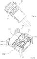
- Figure 2 shows an exploded illustration of the first connector 10 illustrated in Figs. 1a and 1b .
- the flexible arm 33 extends along mating axis Z at the same distance as the elongated housing 20.
- the second locking means is a connector position assurance device 50 attached to the elongated housing 20, wherein the connector position assurance device 50 is movable along the longitudinal axis X between an open position O and a blocked position B, when the connector assembly is mated.
- the connector position assurance device 50 comprises a main part 51 aligned along the transversal axis Y.
- the connector position assurance device 50 comprises also a bar shaped portion 52 protruding from the main part 51 along the longitudinal axis X towards the elongating housing 20.
- the connector position assurance device 50 comprises also a safety arm 60 to lock the connector position assurance device 50 in an unmated condition.
- the safety arm 60 protruding from the main part 51 along the longitudinal axis X towards the elongating housing 20.
- An outwardly sloped safety surface 61 is arranged on the safety arm 60, the second connector comprises a post 160 ( figure 3b ) protruding along the mating axis Z, having an inwardly sloped release surface 161. After mating the sloped safety surface 61 and the sloped release surface 161 cooperate in the way that the safety arm 60 is moved outwardly and the connector position assurance device 50 is movable from the open position O to the blocked position B.
- the position assurance device 50 comprises a final lock protrusion 55 protruding along the mating axis Z.
- the final lock protrusion 55 is protruding from the free end of a final lock arm 54, protruding from the main part 51 along the longitudinal axis X towards the elongated housing 20.
- the final lock protrusion 55 is adapted to cooperate with an edge (not shown) in the elongated housing 20 to lock the position assurance device 50 in the blocked position B.
- the elongating housing 20 comprises cavities to receive terminals 16 attached to electrical wires 12 a Ferrite element 14 surrounding the electrical wires 12. In this embodiment the elongating housing 20 has a cap 20a that covers the cavities.
- the elongating housing 20 comprises openings 22 for guiding the wires 12 through the elongating housing 20.
- the connector position assurance device 50 is attached opposite to the openings 22 at the elongated housing 20.
- the elongated housing 20 comprises a rib 32 extending along the mating axis Z and the shroud 101 comprises a groove 132 ( figure 3b ) extending along the mating axis Z. The rib 32 is received in the groove 132 while mating and guide the first connector 10 inside the second connector 100 while mating.
- Figure 3a shows as schematic view of the first connector's connection face 11.
- FIG 3b shows as schematic view of the second connector 100.
- the second connector 100 comprises contact elements 111 protruding from a second connector's connection face 110, surrounded at least partly by a shroud 101, along the mating axis Z.
- the second connector comprises a post 160 protruding along the mating axis Z, having an inwardly sloped release surface 161. After mating the sloped safety surface 61 and the sloped release surface 161 cooperate in the way, that the safety arm 60 is moved outwardly and the connector position assurance device 50 is movable from the open position O to the blocked position B.
- the third locking means is an edge 103 ( figure 5 , figure 6 ) defined by a recess 134 in an inner wall of the shroud 101.
- Figure 4a shows as schematic view of the electrical connector assembly in a connected state.
- the position assurance device 50 is in an open O position.
- Figure 4b shows the view of figure 4a in wherein the position assurance device 50 is in a blocked B position.
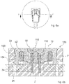
- Figure 5b shows a cut view of the connector assembly shown in figure 5a with a cut along the axis C as shown in the top view above the cut view in figure 5a .
- the connector position assurance device 50 is in the open position O.
- the bar shaped portion 52 has a rectangular cross section and is partly inserted in the guide cavity 24 having also a rectangular cross section.
- the flexible arm 33 is able to be bent inwards the guide cavity 24.
- the protrusion 34 protruding outwards from the elongated housing 20, along the transverse axis Y into a recess 134 in the wall of the shroud 101.
- the edge 103 defined by the recess 134 locks the protrusion 34 and prevents movement along the mating axis Z.
- Figure 6b shows a cut view of the connector assembly shown in figure 6a with a cut along the axis D as shown in the top view above the cut view in figure 6a .
- the connector position assurance device 50 is in the blocked position B.
- the bar shaped portion 52 is fully inserted in the guide cavity 24.
- the flexible arm 33 is not able to be bent inwards the guide cavity 24.
- the protrusion 34 protruding outwards from the elongated housing 20, along the transverse axis Y into the recess 134 in the wall of the shroud 101.
- the edge 103 defined by the recess 134 locks the protrusion 34 and prevents movement along the mating axis Z.
- the first connector 10 comprises terminals 16 and the second connector 100 comprises contact elements 111, wherein in a plane P, spanned by the longitudinal axis X and transversal axis Y, at least, a portion of the terminals 16 and a portion of the contact elements 111 and a portion of the bar shaped portion 52 and a portion of the flexible arm 33, is present in at least at one point along the mating axis Z.
- the terminals 16 and the contact elements 111 have contacting points 112 between the terminals 16 and the contact elements 111.
- a portion of the bar shaped portion 52 and a portion of the flexible arm 33 and the contact points 112 is arranged in a row along the transversal axis Y.
Landscapes
- Details Of Connecting Devices For Male And Female Coupling (AREA)
Abstract
An electrical connector assembly for airbag restraint systems comprising a first connector (10), comprising an elongated housing (20) aligned along a longitudinal axis (X), a first connector's connection face (11) facing perpendicular to the longitudinal axis, along a mating axis (Z) perpendicular to the longitudinal axis, said first connector comprising first locking means to lock the first connector to a second connector (100) and second locking means that prevent the first locking means from releasing, the connector assembly further comprising the second connector, comprising a second connector's connection face (110) surrounded at least partly by a shroud (101), facing along the mating axis towards the first connector's connection face, wherein the shroud comprises third locking means that cooperate with the first locking means to lock the first connector to the second connector when mated along the mating axis, wherein the extension of the mated connector assembly, along the mating axis, is smaller than the extension along the longitudinal axis and also smaller than the extension along a transverse axis (Y) arranged perpendicular to the longitudinal axis and the mating axis.

Description
- The present invention relates to a connector assembly, in particular for airbag restraint systems. The connector assembly comprises a connector housing comprising a connector position assurance device and a counter connector. The connector position assurance device is assigned to the connector housing so that it is movable relative to the connector housing from an open position to a closed position.
- In many applications, the safe coupling of connectors is of high importance. For example, in the case of car safety systems, as e.g. airbag systems in passenger cars, the connectors used for the connection of an airbag to its ignition base have to be provided with reliable safety systems. To ensure that the connectors cannot become loose unintentionally, locking means are used to guarantee a safe mechanical coupling.
- The provision of vehicles in the areas of safety, comfort and multimedia has grown rapidly in recent years. All these new functions require additional electrical and mechanical effort. Additional electrical wiring and plug-in systems must be installed in the vehicle. This led to a trend of miniaturization in the production of vehicles. Smaller cross sections were chosen for the electrical lines and the electrical plug systems were dimensioned smaller. However, there are limits to miniaturization when it comes to keeping the plug-and-socket systems manageable during assembly. In addition, it must be ensured that faulty assembly of the connectors is excluded for safety-relevant plug-in connections. Some years ago a kind of connector type was developed and successfully used in the field so that this connector type has become established in airbag applications. Document
EP2966735 discloses such an air bag connector. This connector has a secondary lock and is used in many vehicles. However, despite its miniaturization, this connector has a certain size. The plug protrudes from the mating connector in the plugged state, which can lead to problems during assembly in very confined spaces. Since the miniaturization now produces plug-in systems that are no longer manageable and larger components, such as ferrite bodies, must also be accommodated, another way must be found to solve the problems. - The object of the invention is to provide an electrical connector assembly for an airbag ignition device, which is easy to handle during assembly, provides a secure plug-in connection and is suitable for narrow building spaces.
- These and other objects which become apparent upon reading the following description are solved by an electrical connector assembly according claim 1.
- According to the invention, electrical connector assembly for airbag restraint systems comprising a first connector, comprising an elongated housing aligned along a longitudinal axis, a first connector connection face facing perpendicular to the longitudinal axis, along a mating axis perpendicular to the longitudinal axis, said first connector comprising first locking means to lock the first connector to a second connector and second locking means that prevent the first locking means from releasing, the connector assembly further comprising the second connector, comprising a second connectors connection face surrounded at least partly by a shroud, facing along the mating axis, towards the first connector's connection face , wherein the shroud comprises third locking means that cooperate with the first locking means to lock the first connector to the second connector when mated along the mating axis, wherein the extension of the mated connector assembly, along the mating axis is smaller than the extension along the longitudinal axis and also smaller than the extension along a transverse axis arranged perpendicular to the longitudinal axis and the mating axis.
- The electrical connector assembly provides a flat connector structure that can be used in narrow environments. The first connector and the second connector are small concerning the mating axis. Furthermore the first connector is preferable fully received in the second connector. That's why the size in mating direction is dependent only on the second connector. The locking means acting only in directions perpendicular to the mating axis and do not require additional space along the mating direction. Due to this there is no need to foresee free space above the first connector in the environment, because the locking means operated perpendicular to the mating axis. That makes the handling while assembly easier.
- Preferably, the first locking means is a protrusion protruding outwards from the elongated housing, along the transverse axis. Because the protrusion protrudes along the transverse axis it doesn't increase space requirement along the mating axis. The protrusion can be designed to extend a distance along the longitudinal axis to be more robust.
- Preferably, the protrusion is arranged on a free end of a flexible arm, wherein the flexible arm extends from the elongated housing along the mating axis towards the second connector. The flexible arm provides flexibility in the way that the protrusion can be displaced inwardly to the elongated housing by the shroud, while mating. Because the flexible arm extends towards the second connector the protrusion comes in contact with the shroud in an early state of mating, the flexible arm, displaced inwardly, is protected from damages.
- Advantageously, the flexible arm extends along mating axis at the same distance as the elongated housing. To increase the flexibility of the flexible arm it should be as long as possible but not increase the size of the first connector.
- Advantageously, third locking means is an edge defined by a recess in an inner wall of the shroud. An easy and cheap way to provide the edge in the shroud is to make a recess. If necessary also a cavity can be provided in the shroud.
- Preferably, the second locking means is a connector position assurance device attached to the elongated housing, wherein the connector position assurance device is movable along the longitudinal axis between an open position and a blocked position, when the connector assembly is mated. The second locking means prevents the connector assembly from accidentally disconnecting. The second locking means is operable along the longitudinal axis and needs no additional space, neither along the transversal axis nor along the mating axis.
- Advantageously, the connector position assurance device comprises main part aligned along the transversal axis. The main part has some functions. It works with handle for the operator while mating the connectors, especially while locking the second locking means. Furthermore the main part works as start point for protrusions needed by the connector position assurance device. Finally the main part defines the wall of the elongated housing in a finally assembled state.
- Preferably, the connector position assurance device comprises a bar shaped portion protruding from the main part along the longitudinal axis towards the elongated housing and wherein the elongated housing comprises a guide cavity aligned along the longitudinal axis and wherein the bar shaped portion is movable inside the guide cavity along the longitudinal axis , when the connector assembly is mated. A portion of the guide cavity surrounding wall is defined by the flexible arm. While mating the flexible arm is bent, at least partly, into the guide cavity. When finally mated the flexible arm is relaxed again, whereby the protrusion protrudes in a predefined opening. The flexible arm defines a portion of the wall, surrounding the guide cavity. The guide cavity is ready to receive the bar shaped portion. The bar shaped portion fills the guide cavity when in the closed position thereby preventing movement of the flexible arm. Without movement of the flexible arm the protrusion is held securely in the predefined opening and locks the first and the second connectors.
- Advantageously, the bar shaped portion and the guide cavity have a rectangular cross section. A rectangular cross section provides good guiding abilities.
- Preferably, the elongated housing comprises openings for guide through electrical wires, wherein the connector position assurance device is attached opposite to the openings at the elongated housing, whereby the connector position assurance device is moved towards the openings while moving from the open position to the blocked position. This arrangement allows, while manually assembling the connectors, to hold and guide the first connector to the correct position using a first hand by holding the electrical wires. In the correct position the connectors can be plugged to and locked by a second hand. The electrical wires do not disturb the operating of the position assurance device.
- Advantageously, the first connector comprises terminals and the second connector comprises contact elements, wherein in a plane, spanned by the longitudinal axis and transversal axis, at least, a portion of the terminals and a portion of the contact elements and a portion of the bar shaped portion and a portion of the flexible arm, is present in one point along the mating axis. This design provides a robust connector. The contact elements are surrounded by the locking means especially in the area where they make contact. This promises high reliability of the electrical connection.
- Preferably, the first connector comprises terminals and the second connector comprises contact elements, wherein contacting points between the terminals and the contact elements and a portion of the bar shaped portion and a portion of the flexible arm is arranged in a row along the transversal axis. This design provides also a robust connector. The contact elements are adjacent to the locking means. This arrangement of contact elements and locking means promises high reliability of the electrical connection.
- Advantageously, the connector position assurance device comprises a safety arm to block the connector position assurance device in an unmated condition. The safety arm protruding from the main part along the longitudinal axis towards the elongated housing comprises an outwardly sloped safety surface that is arranged on the safety arm. The second connector comprises a post protruding along the mating axis, having an inwardly sloped release surface and after mating the sloped safety surface and the sloped release surface cooperate in the way that the safety arm is moved outwardly and the connector position assurance device is movable from the open position to the blocked position. This arrangement prevents an unwanted movement of the position assurance device while the first connector is not connected to the second connector. While mating the connector position assurance device is released.
- Preferably, the position assurance device comprises a final lock protrusion protruding along the mating axis, wherein the final lock protrusion is protruding from the free end of a final lock arm, protruding from the main part along the longitudinal axis towards the elongated housing, whereby the final lock protrusion is adapted to cooperate with an edge in the elongated housing to lock the position assurance device in the blocked position. This arrangement prevents an unwanted movement of the position assurance device when the first connector and the second connector are finally connected, by locking the position assurance device to the first connector.
- Advantageously, the elongated housing comprises a rib extending along the mating axis and the shroud comprises a groove extending along the mating axis, wherein the rib is received in the groove while mating, guiding the connectors while mating. The rib engages with the groove at the beginning of the mating process and guides the first connector precisely along mating axis towards the second connector. This prevents damages at the contact elements.
- In the following, the invention is described exemplarily with reference to the enclosed figures, in which
- Figs. 1a, 1b
- show a schematic illustration of a connector assembly in not connected and connected state;
- Fig. 2
- shows an exploded illustration of the first connector as illustrated in
Figs. 1a and 1b ; - Fig. 3a
- shows a schematic view to the connection face of the first connector;
- Fig. 3b
- shows a schematic view of the second connector;
- Fig. 4a, 4b
- show a schematic illustrations of a connector assembly with connector position assurance device in open position and in closed position;
- Fig. 5a, 5b
- show a cut view of the connector assembly with a cut along the transverse axis, with the connector position assurance device in an open position;
- Fig. 6a, 6b
- show a cut view of the connector assembly with a cut along the transverse axis, with the connector position assurance device in a blocked position;
-
Figure 1a shows an electrical connector assembly for airbag restraint systems in a disconnected status. The electrical connector assembly comprising afirst connector 10 having anelongated housing 20 aligned along a longitudinal axis X. A first connector connection face 11 facing perpendicular to the longitudinal axis X, along a mating axis Z perpendicular to the longitudinal axis X. Thefirst connector 10 comprising first locking means to lock thefirst connector 10 to asecond connector 100 and second locking means that prevent the first locking means from releasing. The connector assembly further comprising thesecond connector 100 having a secondconnector connection face 110, surrounded at least partly by ashroud 101, facing along the mating axis Z, towards the first connector's 10connection face 11. Theshroud 101 comprises third locking means that cooperate with the first locking means to lock thefirst connector 10 to thesecond connector 100 when mated along the mating axis Z. The extension of the mated connector assembly, along the mating axis Z, is smaller than the extension along the longitudinal axis X and also smaller than the extension along a transverse axis Y arranged perpendicular to the longitudinal axis X and the mating axis Z. The first locking means is aprotrusion 34 protruding outwards from theelongated housing 20 along the transverse axis Y. Theprotrusion 34 is arranged on a free end of aflexible arm 33, wherein the flexible arm extends from theelongated housing 20 along the mating axis Z towards thesecond connector 100. The second connector is attached on abase plate 200 of an airbag restraint system.Figure 1b shows an electrical connector assembly in an electrically connected with open connectorposition assurance device 50. -
Figure 2 shows an exploded illustration of thefirst connector 10 illustrated inFigs. 1a and 1b . Theflexible arm 33 extends along mating axis Z at the same distance as theelongated housing 20. The second locking means is a connectorposition assurance device 50 attached to theelongated housing 20, wherein the connectorposition assurance device 50 is movable along the longitudinal axis X between an open position O and a blocked position B, when the connector assembly is mated. The connectorposition assurance device 50 comprises amain part 51 aligned along the transversal axis Y. The connectorposition assurance device 50 comprises also a bar shapedportion 52 protruding from themain part 51 along the longitudinal axis X towards the elongatinghousing 20. The connectorposition assurance device 50 comprises also asafety arm 60 to lock the connectorposition assurance device 50 in an unmated condition. Thesafety arm 60 protruding from themain part 51 along the longitudinal axis X towards the elongatinghousing 20. An outwardly slopedsafety surface 61 is arranged on thesafety arm 60, the second connector comprises a post 160 (figure 3b ) protruding along the mating axis Z, having an inwardly slopedrelease surface 161. After mating the slopedsafety surface 61 and the slopedrelease surface 161 cooperate in the way that thesafety arm 60 is moved outwardly and the connectorposition assurance device 50 is movable from the open position O to the blocked position B. Furthermore theposition assurance device 50 comprises afinal lock protrusion 55 protruding along the mating axis Z. Thefinal lock protrusion 55 is protruding from the free end of afinal lock arm 54, protruding from themain part 51 along the longitudinal axis X towards theelongated housing 20. Thefinal lock protrusion 55 is adapted to cooperate with an edge (not shown) in theelongated housing 20 to lock theposition assurance device 50 in the blocked position B. The elongatinghousing 20 comprises cavities to receiveterminals 16 attached to electrical wires 12 aFerrite element 14 surrounding theelectrical wires 12. In this embodiment the elongatinghousing 20 has acap 20a that covers the cavities. The elongatinghousing 20 comprisesopenings 22 for guiding thewires 12 through the elongatinghousing 20. The connectorposition assurance device 50 is attached opposite to theopenings 22 at theelongated housing 20. Theelongated housing 20 comprises arib 32 extending along the mating axis Z and theshroud 101 comprises a groove 132 (figure 3b ) extending along the mating axis Z. Therib 32 is received in thegroove 132 while mating and guide thefirst connector 10 inside thesecond connector 100 while mating. -
Figure 3a shows as schematic view of the first connector'sconnection face 11. -
Figure 3b shows as schematic view of thesecond connector 100. Thesecond connector 100 comprisescontact elements 111 protruding from a second connector'sconnection face 110, surrounded at least partly by ashroud 101, along the mating axis Z. The second connector comprises apost 160 protruding along the mating axis Z, having an inwardly slopedrelease surface 161. After mating the slopedsafety surface 61 and the slopedrelease surface 161 cooperate in the way, that thesafety arm 60 is moved outwardly and the connectorposition assurance device 50 is movable from the open position O to the blocked position B. The third locking means is an edge 103 (figure 5 ,figure 6 ) defined by arecess 134 in an inner wall of theshroud 101. -
Figure 4a shows as schematic view of the electrical connector assembly in a connected state. Theposition assurance device 50 is in an open O position.Figure 4b shows the view offigure 4a in wherein theposition assurance device 50 is in a blocked B position. -
Figure 5b shows a cut view of the connector assembly shown infigure 5a with a cut along the axis C as shown in the top view above the cut view infigure 5a . The connectorposition assurance device 50 is in the open position O. The bar shapedportion 52 has a rectangular cross section and is partly inserted in theguide cavity 24 having also a rectangular cross section. When the connectorposition assurance device 50 is in the open position O theflexible arm 33 is able to be bent inwards theguide cavity 24. Theprotrusion 34 protruding outwards from theelongated housing 20, along the transverse axis Y into arecess 134 in the wall of theshroud 101. Theedge 103 defined by therecess 134 locks theprotrusion 34 and prevents movement along the mating axis Z. -
Figure 6b shows a cut view of the connector assembly shown infigure 6a with a cut along the axis D as shown in the top view above the cut view infigure 6a . The connectorposition assurance device 50 is in the blocked position B. The bar shapedportion 52 is fully inserted in theguide cavity 24. When the connectorposition assurance device 50 is in the blocked position B theflexible arm 33 is not able to be bent inwards theguide cavity 24. Theprotrusion 34 protruding outwards from theelongated housing 20, along the transverse axis Y into therecess 134 in the wall of theshroud 101. Theedge 103 defined by therecess 134 locks theprotrusion 34 and prevents movement along the mating axis Z. Thefirst connector 10 comprisesterminals 16 and thesecond connector 100 comprisescontact elements 111, wherein in a plane P, spanned by the longitudinal axis X and transversal axis Y, at least, a portion of theterminals 16 and a portion of thecontact elements 111 and a portion of the bar shapedportion 52 and a portion of theflexible arm 33, is present in at least at one point along the mating axis Z. Theterminals 16 and thecontact elements 111 have contactingpoints 112 between theterminals 16 and thecontact elements 111. A portion of the bar shapedportion 52 and a portion of theflexible arm 33 and the contact points 112, is arranged in a row along the transversal axis Y.
Claims (15)
- Electrical connector assembly for airbag restraint systems comprising a first connector (10), comprising an elongated housing (20) aligned along a longitudinal axis (X), a first connector's connection face (11) facing perpendicular to the longitudinal axis, along a mating axis (Z) perpendicular to the longitudinal axis, said first connector comprising first locking means to lock the first connector to a second connector (100), and second locking means that prevent the first locking means from releasing, the connector assembly further comprising the second connector, comprising a second connector's connection face (110) surrounded at least partly by a shroud (101), facing along the mating axis, towards the first connector's connection face, wherein the shroud comprises third locking means that cooperate with the first locking means to lock the first connector to the second connector when mated along the mating axis, wherein the extension of the mated connector assembly, along the mating axis, is smaller than the extension along the longitudinal axis and also smaller than the extension along a transverse axis (Y) arranged perpendicular to the longitudinal axis and the mating axis.
- Electrical connector assembly according to claim 1, wherein the first locking means is a protrusion (34) protruding outwards from the elongated housing (20), along the transverse axis (Y).
- Electrical connector assembly according to claim 2, wherein the protrusion (34) is arranged on a free end of a flexible arm (33), wherein the flexible arm extends from the elongated housing (20) along the mating axis (Z) towards the second connector (100).
- Electrical connector assembly according to claim 3, wherein the flexible arm (33) extends along mating axis (Z) at the same distance, as the elongated housing (20).
- Electrical connector assembly according any preceding claim, wherein the third locking means is an edge (103) defined by a recess (134) in an inner wall of the shroud (101).
- Electrical connector assembly according to any preceding claim, wherein the second locking means is a connector position assurance device (50) attached to the elongated housing (20), wherein the connector position assurance device is movable along the longitudinal axis (X) between an open position (O) and a blocked position (B), when the connector assembly is mated.
- Electrical connector assembly according to claim 6, wherein the connector position assurance device (50) comprises a main part (51) aligned along the transversal axis (Y).
- Electrical connector assembly according to claim 7, wherein the connector position assurance device (50) comprises a bar shaped portion (52) protruding from the main part (51) along the longitudinal axis (X) towards the elongated housing (20) and wherein the elongated housing (20) comprises a guide cavity (24) aligned along the longitudinal axis (X), and wherein the bar shaped portion (52) is movable inside the guide cavity (24) along the longitudinal axis (X), when the connector assembly is mated.
- Electrical connector assembly according to claim 8, wherein the bar shaped portion (52) and the guide cavity (24) have a rectangular cross section.
- Electrical connector assembly according to any of claims 6 to 9, wherein the elongated housing (20) comprises openings (22) for guide through electrical wires (12), wherein the connector position assurance device (50) is attached opposite to the openings (22) at the elongated housing (20), whereby the connector position assurance device (50) is moved towards the openings (22) while moving from the open position (O) to the blocked position (B).
- Electrical connector assembly according to any of claims 8 to 10 in combination with claim 3, wherein the first connector (10) comprises terminals (16) and the second connector (100) comprises contact elements (111), wherein in a plane (P), spanned by the longitudinal axis (X) and transversal axis (Y), at least, a portion of the terminals (16) and a portion of the contact elements (111) and a portion of the bar shaped portion (52) and a portion of the flexible arm (33), is present, in at least at one point along the mating axis (Z).
- Electrical connector assembly according to any of claims 8 to 10 in combination with claim 3, wherein the first connector (10) comprises terminals (16) and the second connector (100) comprises contact elements (111), wherein contacting points (112) between the terminals (16) and the contact elements (111) and a portion of the bar shaped portion (52) and a portion of the flexible arm (33) is arranged in a row along the transversal axis (Y).
- Electrical connector assembly according to any of claims 7 to 12, wherein the connector position assurance device (50) comprises a safety arm (60) to block the connector position assurance device (50) in an unmated condition, the safety arm (60) protruding from the main part (51) along the longitudinal axis (X) towards the elongated housing (20), comprising an outwardly sloped safety surface (61) that is arranged on the safety arm (60), the second connector comprises a post (160) protruding along the mating axis (Z) having an inwardly sloped release surface (161), after mating the sloped safety surface (61) and the sloped release surface (161) cooperate in the way that the safety arm (60) is moved outwardly and the connector position assurance device (50) is movable from the open position (O) to the blocked position (B).
- Electrical connector assembly according to any of claims 7 to 13, wherein the position assurance device (50) comprises a final lock protrusion (55) protruding along the mating axis (Z), wherein the final lock protrusion (55) is protruding from the free end of a final lock arm (54), protruding from the main part (51) along the longitudinal axis (X) towards the elongated housing (20), whereby the final lock protrusion (55) is adapted to cooperate with an edge in the elongated housing (20) to lock the position assurance device (50) in the blocked position (B).
- Electrical connector assembly according to any preceding claim, wherein the elongated housing (20) comprises a rib (32) extending along the mating axis (Z) and the shroud (101) comprises a groove (132) extending along the mating axis (Z), wherein the rib (32) is received in the groove (132) while mating, guiding the connectors while mating.
Priority Applications (5)
| Application Number | Priority Date | Filing Date | Title |
|---|---|---|---|
| EP17168508.4A EP3396790A1 (en) | 2017-04-27 | 2017-04-27 | Connector assembly for safety systems |
| US15/953,609 US10290972B2 (en) | 2017-04-27 | 2018-04-16 | Electrical connector assembly |
| KR1020180047129A KR20180120597A (en) | 2017-04-27 | 2018-04-24 | Connector assembly for safety systems |
| JP2018084956A JP2018190714A (en) | 2017-04-27 | 2018-04-26 | Connector assembly for safety system |
| CN201810383527.5A CN108832427B (en) | 2017-04-27 | 2018-04-26 | Connector assembly for a security system |
Applications Claiming Priority (1)
| Application Number | Priority Date | Filing Date | Title |
|---|---|---|---|
| EP17168508.4A EP3396790A1 (en) | 2017-04-27 | 2017-04-27 | Connector assembly for safety systems |
Publications (1)
| Publication Number | Publication Date |
|---|---|
| EP3396790A1 true EP3396790A1 (en) | 2018-10-31 |
Family
ID=58638795
Family Applications (1)
| Application Number | Title | Priority Date | Filing Date |
|---|---|---|---|
| EP17168508.4A Withdrawn EP3396790A1 (en) | 2017-04-27 | 2017-04-27 | Connector assembly for safety systems |
Country Status (5)
| Country | Link |
|---|---|
| US (1) | US10290972B2 (en) |
| EP (1) | EP3396790A1 (en) |
| JP (1) | JP2018190714A (en) |
| KR (1) | KR20180120597A (en) |
| CN (1) | CN108832427B (en) |
Cited By (1)
| Publication number | Priority date | Publication date | Assignee | Title |
|---|---|---|---|---|
| CN115483569A (en) * | 2021-06-14 | 2022-12-16 | 纬湃科技有限责任公司 | High temperature sensor housing with thermocouple connector and method of manufacturing the same |
Families Citing this family (6)
| Publication number | Priority date | Publication date | Assignee | Title |
|---|---|---|---|---|
| JP7042711B2 (en) * | 2018-07-03 | 2022-03-28 | モレックス エルエルシー | Connector and connector assembly |
| US11183793B2 (en) | 2018-10-08 | 2021-11-23 | Aptiv Technologies Limited | Connector system with a terminal retaining device having a reverse hinged lock feature |
| US11171440B2 (en) * | 2019-03-20 | 2021-11-09 | Aptiv Technologies Limited | Backing plate for mounting and sealing an electrical connector to an intermediate surface |
| CN210326329U (en) * | 2019-06-21 | 2020-04-14 | 重庆市鸿腾科技有限公司 | Socket connector and plug connector connected with same |
| DE102021000957A1 (en) * | 2021-02-23 | 2022-08-25 | Kostal Kontakt Systeme Gmbh | High voltage connector assembly |
| US11557855B2 (en) * | 2021-05-03 | 2023-01-17 | Te Connectivity Solutions Gmbh | Low profile angled connector |
Citations (6)
| Publication number | Priority date | Publication date | Assignee | Title |
|---|---|---|---|---|
| US5435742A (en) * | 1994-02-14 | 1995-07-25 | Molex Incorporated | Electrical connector position assurance system |
| EP0734101A2 (en) * | 1995-03-20 | 1996-09-25 | Molex Incorporated | Electrical connector position assurance system |
| US20130276659A1 (en) * | 2012-04-18 | 2013-10-24 | Autoliv Asp, Inc. | Low-profile igniter assemblies adapted for use with inflatable airbag systems |
| EP2685570A1 (en) * | 2012-07-12 | 2014-01-15 | Tyco Electronics UK Limited | Electrical plug-in connector assembly with locking member |
| WO2014087430A1 (en) * | 2012-12-07 | 2014-06-12 | Tyco Electronics Uk Ltd | Electrical connector and assembly therewith having a spring-apart function |
| EP2966735A1 (en) | 2014-07-11 | 2016-01-13 | Delphi International Operations Luxembourg S.à r.l. | Connector assembly with dual secondary lock |
Family Cites Families (33)
| Publication number | Priority date | Publication date | Assignee | Title |
|---|---|---|---|---|
| EP0975063B1 (en) * | 1996-04-30 | 2003-04-09 | Fci | A connector with a lateral cable outlet |
| BRPI0105829B1 (en) * | 2000-11-17 | 2016-05-24 | Framatome Connectors Int | plug connector |
| JP2002324638A (en) * | 2001-04-26 | 2002-11-08 | Jst Mfg Co Ltd | Electrical connection device with latch |
| JP3607883B2 (en) * | 2001-06-22 | 2005-01-05 | 日本圧着端子製造株式会社 | Electrical connection device with latch |
| US6464542B1 (en) * | 2001-07-19 | 2002-10-15 | Hon Hai Precision Ind. Co., Ltd. | Connector assembly having small profile |
| DE10224757B3 (en) * | 2002-06-04 | 2004-01-29 | Fci | Plug connector with secondary locking that locks during the plugging process |
| DE10227016B4 (en) * | 2002-06-17 | 2004-06-03 | Amphenol-Tuchel Electronics Gmbh | Electrical connector |
| DE10242074B3 (en) * | 2002-09-11 | 2004-05-19 | Fci | Spring loaded secondary locking connector |
| US6705886B1 (en) * | 2003-01-23 | 2004-03-16 | Fci Americas Technology, Inc. | Electrical connector having connector position assurance member |
| US6811424B2 (en) * | 2003-03-26 | 2004-11-02 | Fci Americas Technology, Inc. | Electrical connector having connector position assurance member |
| DE102004034321B3 (en) * | 2004-07-15 | 2006-01-12 | Amphenol-Tuchel Electronics Gmbh | Electrical connector |
| JP2006114411A (en) * | 2004-10-15 | 2006-04-27 | Tyco Electronics Amp Kk | Connector housing and electric connector |
| DE102005001515B4 (en) * | 2005-01-13 | 2008-01-31 | Amphenol-Tuchel Electronics Gmbh | Electrical connector |
| US7131854B1 (en) * | 2005-08-31 | 2006-11-07 | Lear Corporation | Electrical connector and airbag apparatus having an electrical connector |
| US7344403B2 (en) * | 2006-01-31 | 2008-03-18 | Fci Americas Technology, Inc. | Squib connector with improved cover connection |
| US7351089B2 (en) * | 2006-04-28 | 2008-04-01 | Delphi Technologies, Inc. | Electrical connector having a CPA plug |
| JP4752606B2 (en) * | 2006-05-15 | 2011-08-17 | 住友電装株式会社 | connector |
| US7306474B1 (en) * | 2006-10-16 | 2007-12-11 | Fci Americas Technology, Inc. | Electrical connector with scoop proof dome |
| US7503793B2 (en) * | 2007-01-18 | 2009-03-17 | Delphi Technologies, Inc. | Electrical connector body having a transverse hold-down beam for a shroud-integrated lock arm |
| KR20090062657A (en) * | 2007-12-13 | 2009-06-17 | 현대자동차주식회사 | Squib Connector Connection Structure of Airbag Inflator |
| CN201178146Y (en) * | 2008-03-05 | 2009-01-07 | 富士康(昆山)电脑接插件有限公司 | Electrical connectors and electrical connector components |
| JP5471607B2 (en) * | 2010-03-03 | 2014-04-16 | 住友電装株式会社 | Connector assembly jig |
| US9325114B2 (en) * | 2010-09-01 | 2016-04-26 | Molex, Llc | Plug connector |
| KR101879473B1 (en) * | 2011-04-22 | 2018-07-17 | 델피 인터내셔널 오퍼레이션즈 룩셈부르크 에스.에이 알.엘. | Airbag connector system |
| CA2834393A1 (en) | 2011-04-29 | 2012-11-01 | Danisco Us Inc. | Single ph process for starch liquefaction and saccharification for high-density glucose syrups |
| JP5813419B2 (en) * | 2011-08-30 | 2015-11-17 | 矢崎総業株式会社 | Connector and structure for fixing connector to support member |
| IN2014CN03639A (en) * | 2011-10-20 | 2015-07-03 | Delphi Int Operations Lux Srl | |
| KR102011385B1 (en) * | 2012-11-12 | 2019-08-16 | 앱티브 테크놀러지스 리미티드 | Connector assembly with automatic secondary lock |
| JP2014110182A (en) * | 2012-12-03 | 2014-06-12 | Jst Mfg Co Ltd | Electric connector, and connection device of squib |
| EP3005486B1 (en) * | 2013-06-07 | 2019-09-11 | Amphenol FCI Asia Pte. Ltd. | Electrical connector |
| WO2015036609A1 (en) * | 2013-09-16 | 2015-03-19 | Tyco Electronics France Sas | Spring-lock connector |
| TWM470405U (en) * | 2013-09-27 | 2014-01-11 | Bellwether Electronic Corp | Electrical connector |
| US8968021B1 (en) * | 2013-12-11 | 2015-03-03 | JAE Oregon, Inc. | Self-rejecting automotive harness connector |
-
2017
- 2017-04-27 EP EP17168508.4A patent/EP3396790A1/en not_active Withdrawn
-
2018
- 2018-04-16 US US15/953,609 patent/US10290972B2/en not_active Expired - Fee Related
- 2018-04-24 KR KR1020180047129A patent/KR20180120597A/en not_active Withdrawn
- 2018-04-26 CN CN201810383527.5A patent/CN108832427B/en not_active Expired - Fee Related
- 2018-04-26 JP JP2018084956A patent/JP2018190714A/en active Pending
Patent Citations (6)
| Publication number | Priority date | Publication date | Assignee | Title |
|---|---|---|---|---|
| US5435742A (en) * | 1994-02-14 | 1995-07-25 | Molex Incorporated | Electrical connector position assurance system |
| EP0734101A2 (en) * | 1995-03-20 | 1996-09-25 | Molex Incorporated | Electrical connector position assurance system |
| US20130276659A1 (en) * | 2012-04-18 | 2013-10-24 | Autoliv Asp, Inc. | Low-profile igniter assemblies adapted for use with inflatable airbag systems |
| EP2685570A1 (en) * | 2012-07-12 | 2014-01-15 | Tyco Electronics UK Limited | Electrical plug-in connector assembly with locking member |
| WO2014087430A1 (en) * | 2012-12-07 | 2014-06-12 | Tyco Electronics Uk Ltd | Electrical connector and assembly therewith having a spring-apart function |
| EP2966735A1 (en) | 2014-07-11 | 2016-01-13 | Delphi International Operations Luxembourg S.à r.l. | Connector assembly with dual secondary lock |
Cited By (1)
| Publication number | Priority date | Publication date | Assignee | Title |
|---|---|---|---|---|
| CN115483569A (en) * | 2021-06-14 | 2022-12-16 | 纬湃科技有限责任公司 | High temperature sensor housing with thermocouple connector and method of manufacturing the same |
Also Published As
| Publication number | Publication date |
|---|---|
| US20180316130A1 (en) | 2018-11-01 |
| JP2018190714A (en) | 2018-11-29 |
| KR20180120597A (en) | 2018-11-06 |
| CN108832427B (en) | 2020-06-09 |
| US10290972B2 (en) | 2019-05-14 |
| CN108832427A (en) | 2018-11-16 |
Similar Documents
| Publication | Publication Date | Title |
|---|---|---|
| CN108832427B (en) | Connector assembly for a security system | |
| EP2700130B1 (en) | Airbag connector system | |
| CN109863649B (en) | Electric plug-in connector | |
| KR102516478B1 (en) | Connector assembly | |
| US10312632B2 (en) | Connector | |
| EP2966735B1 (en) | Connector assembly with dual secondary lock | |
| US9614327B2 (en) | Electrical connector and assembly therewith having a spring-apart function | |
| CN104067455A (en) | Connector and method of making the same | |
| CN107710517A (en) | Joint connector | |
| EP3396789B1 (en) | Connector for airbag restraint systems | |
| CN111834788B (en) | Electrical terminal housing with terminal lock | |
| EP1701414A1 (en) | Electrical connector | |
| EP3312941B1 (en) | Connector assembly with dual secondary lock | |
| CN115347415B (en) | Electrical connector including connector position assurance element | |
| US9196993B2 (en) | Connector unit | |
| JP2010118150A (en) | Connector | |
| US20250233361A1 (en) | Electrical connector having a mated verficiation switch | |
| EP3487010B1 (en) | Electrical connector | |
| US9705226B1 (en) | Center load terminal position assurance for an electrical connector |
Legal Events
| Date | Code | Title | Description |
|---|---|---|---|
| PUAI | Public reference made under article 153(3) epc to a published international application that has entered the european phase |
Free format text: ORIGINAL CODE: 0009012 |
|
| AK | Designated contracting states |
Kind code of ref document: A1 Designated state(s): AL AT BE BG CH CY CZ DE DK EE ES FI FR GB GR HR HU IE IS IT LI LT LU LV MC MK MT NL NO PL PT RO RS SE SI SK SM TR |
|
| AX | Request for extension of the european patent |
Extension state: BA ME |
|
| RAP1 | Party data changed (applicant data changed or rights of an application transferred) |
Owner name: APTIV TECHNOLOGIES LIMITED |
|
| STAA | Information on the status of an ep patent application or granted ep patent |
Free format text: STATUS: THE APPLICATION IS DEEMED TO BE WITHDRAWN |
|
| 18D | Application deemed to be withdrawn |
Effective date: 20190501 |