EP3396584A2 - Optical compensation for image scanner - Google Patents
Optical compensation for image scanner Download PDFInfo
- Publication number
- EP3396584A2 EP3396584A2 EP18161783.8A EP18161783A EP3396584A2 EP 3396584 A2 EP3396584 A2 EP 3396584A2 EP 18161783 A EP18161783 A EP 18161783A EP 3396584 A2 EP3396584 A2 EP 3396584A2
- Authority
- EP
- European Patent Office
- Prior art keywords
- service terminal
- scanner
- component
- optical
- optical symbol
- Prior art date
- Legal status (The legal status is an assumption and is not a legal conclusion. Google has not performed a legal analysis and makes no representation as to the accuracy of the status listed.)
- Withdrawn
Links
Images


Classifications
-
- G—PHYSICS
- G07—CHECKING-DEVICES
- G07G—REGISTERING THE RECEIPT OF CASH, VALUABLES, OR TOKENS
- G07G1/00—Cash registers
- G07G1/0036—Checkout procedures
- G07G1/0045—Checkout procedures with a code reader for reading of an identifying code of the article to be registered, e.g. barcode reader or radio-frequency identity [RFID] reader
- G07G1/0054—Checkout procedures with a code reader for reading of an identifying code of the article to be registered, e.g. barcode reader or radio-frequency identity [RFID] reader with control of supplementary check-parameters, e.g. weight or number of articles
- G07G1/0072—Checkout procedures with a code reader for reading of an identifying code of the article to be registered, e.g. barcode reader or radio-frequency identity [RFID] reader with control of supplementary check-parameters, e.g. weight or number of articles with means for detecting the weight of the article of which the code is read, for the verification of the registration
-
- G—PHYSICS
- G06—COMPUTING OR CALCULATING; COUNTING
- G06K—GRAPHICAL DATA READING; PRESENTATION OF DATA; RECORD CARRIERS; HANDLING RECORD CARRIERS
- G06K7/00—Methods or arrangements for sensing record carriers, e.g. for reading patterns
- G06K7/10—Methods or arrangements for sensing record carriers, e.g. for reading patterns by electromagnetic radiation, e.g. optical sensing; by corpuscular radiation
- G06K7/14—Methods or arrangements for sensing record carriers, e.g. for reading patterns by electromagnetic radiation, e.g. optical sensing; by corpuscular radiation using light without selection of wavelength, e.g. sensing reflected white light
- G06K7/1404—Methods for optical code recognition
-
- G—PHYSICS
- G07—CHECKING-DEVICES
- G07G—REGISTERING THE RECEIPT OF CASH, VALUABLES, OR TOKENS
- G07G1/00—Cash registers
- G07G1/0036—Checkout procedures
- G07G1/0045—Checkout procedures with a code reader for reading of an identifying code of the article to be registered, e.g. barcode reader or radio-frequency identity [RFID] reader
- G07G1/0081—Checkout procedures with a code reader for reading of an identifying code of the article to be registered, e.g. barcode reader or radio-frequency identity [RFID] reader the reader being a portable scanner or data reader
-
- G—PHYSICS
- G06—COMPUTING OR CALCULATING; COUNTING
- G06K—GRAPHICAL DATA READING; PRESENTATION OF DATA; RECORD CARRIERS; HANDLING RECORD CARRIERS
- G06K19/00—Record carriers for use with machines and with at least a part designed to carry digital markings
- G06K19/06—Record carriers for use with machines and with at least a part designed to carry digital markings characterised by the kind of the digital marking, e.g. shape, nature, code
- G06K19/06009—Record carriers for use with machines and with at least a part designed to carry digital markings characterised by the kind of the digital marking, e.g. shape, nature, code with optically detectable marking
- G06K19/06018—Record carriers for use with machines and with at least a part designed to carry digital markings characterised by the kind of the digital marking, e.g. shape, nature, code with optically detectable marking one-dimensional coding
- G06K19/06028—Record carriers for use with machines and with at least a part designed to carry digital markings characterised by the kind of the digital marking, e.g. shape, nature, code with optically detectable marking one-dimensional coding using bar codes
-
- G—PHYSICS
- G06—COMPUTING OR CALCULATING; COUNTING
- G06K—GRAPHICAL DATA READING; PRESENTATION OF DATA; RECORD CARRIERS; HANDLING RECORD CARRIERS
- G06K19/00—Record carriers for use with machines and with at least a part designed to carry digital markings
- G06K19/06—Record carriers for use with machines and with at least a part designed to carry digital markings characterised by the kind of the digital marking, e.g. shape, nature, code
- G06K19/06009—Record carriers for use with machines and with at least a part designed to carry digital markings characterised by the kind of the digital marking, e.g. shape, nature, code with optically detectable marking
- G06K19/06037—Record carriers for use with machines and with at least a part designed to carry digital markings characterised by the kind of the digital marking, e.g. shape, nature, code with optically detectable marking multi-dimensional coding
-
- G—PHYSICS
- G06—COMPUTING OR CALCULATING; COUNTING
- G06K—GRAPHICAL DATA READING; PRESENTATION OF DATA; RECORD CARRIERS; HANDLING RECORD CARRIERS
- G06K19/00—Record carriers for use with machines and with at least a part designed to carry digital markings
- G06K19/06—Record carriers for use with machines and with at least a part designed to carry digital markings characterised by the kind of the digital marking, e.g. shape, nature, code
- G06K19/06009—Record carriers for use with machines and with at least a part designed to carry digital markings characterised by the kind of the digital marking, e.g. shape, nature, code with optically detectable marking
- G06K19/06046—Constructional details
- G06K19/0614—Constructional details the marking being selective to wavelength, e.g. color barcode or barcodes only visible under UV or IR
-
- G—PHYSICS
- G06—COMPUTING OR CALCULATING; COUNTING
- G06K—GRAPHICAL DATA READING; PRESENTATION OF DATA; RECORD CARRIERS; HANDLING RECORD CARRIERS
- G06K7/00—Methods or arrangements for sensing record carriers, e.g. for reading patterns
- G06K7/10—Methods or arrangements for sensing record carriers, e.g. for reading patterns by electromagnetic radiation, e.g. optical sensing; by corpuscular radiation
- G06K7/10544—Methods or arrangements for sensing record carriers, e.g. for reading patterns by electromagnetic radiation, e.g. optical sensing; by corpuscular radiation by scanning of the records by radiation in the optical part of the electromagnetic spectrum
- G06K7/10712—Fixed beam scanning
- G06K7/10722—Photodetector array or CCD scanning
-
- G—PHYSICS
- G06—COMPUTING OR CALCULATING; COUNTING
- G06K—GRAPHICAL DATA READING; PRESENTATION OF DATA; RECORD CARRIERS; HANDLING RECORD CARRIERS
- G06K7/00—Methods or arrangements for sensing record carriers, e.g. for reading patterns
- G06K7/10—Methods or arrangements for sensing record carriers, e.g. for reading patterns by electromagnetic radiation, e.g. optical sensing; by corpuscular radiation
- G06K7/10544—Methods or arrangements for sensing record carriers, e.g. for reading patterns by electromagnetic radiation, e.g. optical sensing; by corpuscular radiation by scanning of the records by radiation in the optical part of the electromagnetic spectrum
- G06K7/10821—Methods or arrangements for sensing record carriers, e.g. for reading patterns by electromagnetic radiation, e.g. optical sensing; by corpuscular radiation by scanning of the records by radiation in the optical part of the electromagnetic spectrum further details of bar or optical code scanning devices
- G06K7/10881—Methods or arrangements for sensing record carriers, e.g. for reading patterns by electromagnetic radiation, e.g. optical sensing; by corpuscular radiation by scanning of the records by radiation in the optical part of the electromagnetic spectrum further details of bar or optical code scanning devices constructional details of hand-held scanners
-
- G—PHYSICS
- G06—COMPUTING OR CALCULATING; COUNTING
- G06K—GRAPHICAL DATA READING; PRESENTATION OF DATA; RECORD CARRIERS; HANDLING RECORD CARRIERS
- G06K7/00—Methods or arrangements for sensing record carriers, e.g. for reading patterns
- G06K7/10—Methods or arrangements for sensing record carriers, e.g. for reading patterns by electromagnetic radiation, e.g. optical sensing; by corpuscular radiation
- G06K7/10544—Methods or arrangements for sensing record carriers, e.g. for reading patterns by electromagnetic radiation, e.g. optical sensing; by corpuscular radiation by scanning of the records by radiation in the optical part of the electromagnetic spectrum
- G06K7/10821—Methods or arrangements for sensing record carriers, e.g. for reading patterns by electromagnetic radiation, e.g. optical sensing; by corpuscular radiation by scanning of the records by radiation in the optical part of the electromagnetic spectrum further details of bar or optical code scanning devices
- G06K7/1096—Methods or arrangements for sensing record carriers, e.g. for reading patterns by electromagnetic radiation, e.g. optical sensing; by corpuscular radiation by scanning of the records by radiation in the optical part of the electromagnetic spectrum further details of bar or optical code scanning devices the scanner having more than one scanning window, e.g. two substantially orthogonally placed scanning windows for integration into a check-out counter of a super-market
-
- G—PHYSICS
- G06—COMPUTING OR CALCULATING; COUNTING
- G06K—GRAPHICAL DATA READING; PRESENTATION OF DATA; RECORD CARRIERS; HANDLING RECORD CARRIERS
- G06K7/00—Methods or arrangements for sensing record carriers, e.g. for reading patterns
- G06K7/10—Methods or arrangements for sensing record carriers, e.g. for reading patterns by electromagnetic radiation, e.g. optical sensing; by corpuscular radiation
- G06K7/14—Methods or arrangements for sensing record carriers, e.g. for reading patterns by electromagnetic radiation, e.g. optical sensing; by corpuscular radiation using light without selection of wavelength, e.g. sensing reflected white light
-
- G—PHYSICS
- G06—COMPUTING OR CALCULATING; COUNTING
- G06K—GRAPHICAL DATA READING; PRESENTATION OF DATA; RECORD CARRIERS; HANDLING RECORD CARRIERS
- G06K7/00—Methods or arrangements for sensing record carriers, e.g. for reading patterns
- G06K7/10—Methods or arrangements for sensing record carriers, e.g. for reading patterns by electromagnetic radiation, e.g. optical sensing; by corpuscular radiation
- G06K7/14—Methods or arrangements for sensing record carriers, e.g. for reading patterns by electromagnetic radiation, e.g. optical sensing; by corpuscular radiation using light without selection of wavelength, e.g. sensing reflected white light
- G06K7/1404—Methods for optical code recognition
- G06K7/1408—Methods for optical code recognition the method being specifically adapted for the type of code
- G06K7/1413—1D bar codes
-
- G—PHYSICS
- G06—COMPUTING OR CALCULATING; COUNTING
- G06K—GRAPHICAL DATA READING; PRESENTATION OF DATA; RECORD CARRIERS; HANDLING RECORD CARRIERS
- G06K7/00—Methods or arrangements for sensing record carriers, e.g. for reading patterns
- G06K7/10—Methods or arrangements for sensing record carriers, e.g. for reading patterns by electromagnetic radiation, e.g. optical sensing; by corpuscular radiation
- G06K7/14—Methods or arrangements for sensing record carriers, e.g. for reading patterns by electromagnetic radiation, e.g. optical sensing; by corpuscular radiation using light without selection of wavelength, e.g. sensing reflected white light
- G06K7/1404—Methods for optical code recognition
- G06K7/1408—Methods for optical code recognition the method being specifically adapted for the type of code
- G06K7/1417—2D bar codes
-
- G—PHYSICS
- G06—COMPUTING OR CALCULATING; COUNTING
- G06K—GRAPHICAL DATA READING; PRESENTATION OF DATA; RECORD CARRIERS; HANDLING RECORD CARRIERS
- G06K7/00—Methods or arrangements for sensing record carriers, e.g. for reading patterns
- G06K7/10—Methods or arrangements for sensing record carriers, e.g. for reading patterns by electromagnetic radiation, e.g. optical sensing; by corpuscular radiation
- G06K7/14—Methods or arrangements for sensing record carriers, e.g. for reading patterns by electromagnetic radiation, e.g. optical sensing; by corpuscular radiation using light without selection of wavelength, e.g. sensing reflected white light
- G06K7/1404—Methods for optical code recognition
- G06K7/1439—Methods for optical code recognition including a method step for retrieval of the optical code
- G06K7/1447—Methods for optical code recognition including a method step for retrieval of the optical code extracting optical codes from image or text carrying said optical code
-
- G—PHYSICS
- G06—COMPUTING OR CALCULATING; COUNTING
- G06K—GRAPHICAL DATA READING; PRESENTATION OF DATA; RECORD CARRIERS; HANDLING RECORD CARRIERS
- G06K7/00—Methods or arrangements for sensing record carriers, e.g. for reading patterns
- G06K7/10—Methods or arrangements for sensing record carriers, e.g. for reading patterns by electromagnetic radiation, e.g. optical sensing; by corpuscular radiation
- G06K7/14—Methods or arrangements for sensing record carriers, e.g. for reading patterns by electromagnetic radiation, e.g. optical sensing; by corpuscular radiation using light without selection of wavelength, e.g. sensing reflected white light
- G06K7/1404—Methods for optical code recognition
- G06K7/146—Methods for optical code recognition the method including quality enhancement steps
-
- G—PHYSICS
- G06—COMPUTING OR CALCULATING; COUNTING
- G06K—GRAPHICAL DATA READING; PRESENTATION OF DATA; RECORD CARRIERS; HANDLING RECORD CARRIERS
- G06K7/00—Methods or arrangements for sensing record carriers, e.g. for reading patterns
- G06K7/10—Methods or arrangements for sensing record carriers, e.g. for reading patterns by electromagnetic radiation, e.g. optical sensing; by corpuscular radiation
- G06K7/14—Methods or arrangements for sensing record carriers, e.g. for reading patterns by electromagnetic radiation, e.g. optical sensing; by corpuscular radiation using light without selection of wavelength, e.g. sensing reflected white light
- G06K7/1404—Methods for optical code recognition
- G06K7/146—Methods for optical code recognition the method including quality enhancement steps
- G06K7/1473—Methods for optical code recognition the method including quality enhancement steps error correction
Definitions
- the optical symbol may be a bar code, a quick response code, or a distinct image.
- the data associated with the component may be encoded within the optical symbol.
- the data associated with the component may be a pointer to a location within a database storing configuration data for the component.
- a service terminal including a processor; and a memory storing instructions that, when executed by the processor, cause the processor to: receive, from a scanner, an image of an optical symbol, the optical symbol including data associated with a component of the service terminal; and update a process executable by the processor using the data associated with the component.
- the scanner may be integrated with the service terminal.
- the scanner may be a handheld scanner in electrical communication with the service terminal.
- a service terminal including a top plate including a scanning window and an optical symbol attached to an underside of the top plate; and a scanner located proximate the top plate and operable to: capture a first image, the first image including the optical symbol when top plate may be installed on the service terminal, and apply a color correction to a second image, the second image being of a product code associated with an item being purchased by a user.
- the optical symbol may be not visible to the scanner when the service terminal may be in operation.
- FIG. 1 shows a schematic of a service terminal 100.
- the service terminal 100 may include a scanner 102, a top plate 104, and a computing device 106.
- the top plate 106 may include a window 108 and an optical symbol 110.
- the top plate 104 or other components may be installed or replaced.
- the components may be optical component or non-optical components.
- Non-limiting of optical components include mirrors, lenses, and window glass (such as window 108).
- Non-limiting examples of non-optical components include scales, memory modules, printers, etc. Multiple components may also be considered together as a single optical assembly, non-optical assembly, or combination thereof.
- the scanner 102 may use white light with color sensors.
- the scanner may be sensitive to variations in component optical properties.
- the color as seen by the scanner 104 may be "white balanced" to optimize 1D scan performance while simultaneously providing red-filtered images to read codes. Therefore, any unexpected shift in optical system color properties may change the white balance, and reduces scan performance.
- algorithms executed by the computing device may automatically compensate for color variations, but may also be sensitive to transmissivity.
- other examples of optical properties may include, but are not limited to color shift, optical transmissivity, anti-reflection capability, and clarity (resolution or haze).
- the optical properties may be a property of the window 108.
- the window 108 may include a sapphire layer that may give the window 108 a blue tint. As a result, the window 108 may act as a filter.
- the computing device 106 may compensate for any filtering, loses, or other distortions that may be caused by the window 108.
- flatbed scanners may require highly durable top plate glass window materials, and these glass materials may vary greatly in their color metric properties. For instance, sapphire and a tempered glass may have different properties. Some glasses may have a relatively neutral color profile while sapphire may have a distinct blue shift. Scanners, such as scanner 102 may be a common component across a variety of barcode scanners that may include different glasses. Thus, as disclosed herein, the scanner may be used to scan the optical symbol 110 and obtain information about the properties of the window 108. The properties may be directly encoded within the optical symbol 110 or the optical symbol 110 may be a pointer that allows the computing device 106 to retrieve the optical properties from a database.
- the scanner 102 may also be a separate component that interfaces with the computing device 106.
- the scanner 102 may be handheld scanner that may attach to the service terminal 100 or computing device 106 via a USB port or other communication port.
- the optical symbol 110 may not be visible to the scanner 102 and may be scanned during installation of the top plate.
- a maintenance technician may scan the optical symbol 110.
- the computing device 106 may extract optical information from the optical symbol 110 or retrieve the optical information from a database as disclosed herein.
- the optical symbol 110 is a geometric shape or series of dots, it can be placed where it is visible to the scanner 102 during normal operation.
- the series of dots could be etched in the top surface of the top plate 104 such that they are always visible.
- the scanner 102 may scan the optical symbol 110 as described above.
- the scanner 102 may optimize scale error messages as follows. It is common for cashiers to accidentally press the scanner scale-zero button with the top plate 104 removed, which triggers a scanner voice message with instructions to correct like "Replace the top plate.” Unfortunately, because the scanner does not know the exact top plate tare weight, it is hard for the service terminal 100 to differentiate a missing top plate from other problems.
- One example of an "other problem” is an item left on the top plate 104 during startup of the service terminal 100 and then subsequently removed, which calls for a different voice message "Reset the scanner or reboot the POS.”
- the service terminal 100 can accurately identify the missing top plate and deliver the best corrective action message.
- the computing device 106 may include a computing environment 202, which may include a processor 206 and a memory unit 208.
- the memory unit 208 may include a software module 210, component data 212, and configuration data 214.
- the component data 212 may include the optical properties of the window 108 and other components of the service terminal 100.
- the component data 212 may be stored in a database stored within the memory 208.
- the configuration data 214 may include software or other algorithms as disclosed herein for configuring the service terminal 100 using the component data 212. For instance, executing on the processor 206, the software module 210, component data 112, and configuration data 214 may perform processes for maintaining, updating, and configuring a service terminal, including, for example, one or more stages included in method 300 described below with respect to FIG. 3 .
- the computing device 106 may also include a user interface 216.
- the user interface 216 may include any number of devices that allow a user to interface with the computing device 106 or service terminal 100. Non-limiting examples of the user interface 216 may include a keypad, a microphone, a speaker, a display (touchscreen or otherwise), etc.
- the computing device 106 may also include a communications port 218.
- the communications port 218 may allow the computing device 106 or service terminal 100 to communicate with information systems such as a remote server that may include the optical properties of the window 108.
- information systems such as a remote server that may include the optical properties of the window 108.
- Non-limiting examples of the communications port 218 may include, Ethernet cards (wireless or wired), Bluetooth® transmitters and receivers, near-field communications modules, cellular modules, USB port, etc.
- the method 300 may proceed to stage 304 where a process executed by the service terminal 100 or computing device 106 may be updated.
- the computing device 106 may receive optical properties for the window 108 (either directly from the optical symbol 110 or by retrieving it from a database).
- the computing device 106 may update one or more processes or algorithms executed by the computing device 106.
- the optical properties may indicate a loss associated with an image due to the window 108 having a low transmissivity or a color shift due to a tint of the window 108.
- the computing device 106 can add a correction factor or color correction to a second image scanned by the scanner 102 accordingly.
- Updating a process executed by the computing device 106 or service terminal 100 may include updating software. For example, upon scanning the optical symbol 110, lines of code or variables used by the code may be replaced and updated.
- the software may utilize the transmissivity of the window 108 and after the scanning of the optical symbol 110, the transmissivity of the window 108 may be saved in the memory 208.
- the method 300 can occur at startup of the service terminal 100, during manufacturing of the service terminal 100, or when maintenance is performed on the service terminal 100.
- the computing device 106 may also retrieve software updates. For example, after scanning the optical symbol 110, the computing device 106 may access a remote service and download a software update.
- the software update may be part of regular updates and the optical symbol 110 may be a pointer to a location where the updates may be found.
- the component data identified by the optical symbol 110 may require additional drivers or other software to make a component function.
- the optical symbol 110 may be applied to a scale and during installation of the scale, the scanner 102 may scan the optical symbol 110 and download drivers for the scale.
Landscapes
- Physics & Mathematics (AREA)
- Engineering & Computer Science (AREA)
- General Physics & Mathematics (AREA)
- Theoretical Computer Science (AREA)
- Electromagnetism (AREA)
- General Health & Medical Sciences (AREA)
- Artificial Intelligence (AREA)
- Computer Vision & Pattern Recognition (AREA)
- Toxicology (AREA)
- Health & Medical Sciences (AREA)
- Quality & Reliability (AREA)
- Facsimile Scanning Arrangements (AREA)
- Image Input (AREA)
- Cash Registers Or Receiving Machines (AREA)
Abstract
Description
- Service terminals have become ubiquitous within the retail and banking environments. At the retail level, service terminals reduce labor requirements and increase check-out efficiency by allowing one cashier to oversee many check-out lanes. Within the financial services sector, service terminals, or automated teller machines, allow banking and other financial customers to make withdrawals and deposits or perform other financial transactions without having to find time to visit a financial institution during banker's hours or even visit a financial institution.
- Disclosed herein are systems and methods for configuring a service terminal. The systems and methods may include reading a code located on a component of the service terminal using a scanner and updating a process executable by the service terminal using data associated with the component. The scanner may be in electrical communication with the service terminal. The code may include data associated with the component.
- According to a first aspect of the present invention, there is provided a method of configuring a service terminal, the method including reading an optical symbol located on a component of the service terminal using a scanner, the scanner in electrical communication with the service terminal, the optical symbol including data associated with the component; and updating a process executable by the service terminal using the data associated with the component.
- Optionally, the data may include optical data for a window associated with the scanner.
- Optionally, the scanner may be integrated with the service terminal.
- Optionally, the scanner may be a handheld scanner in electrical communication with the service terminal.
- Optionally, the optical symbol may be a bar code, a quick response code, or a distinct image.
- Optionally, the data associated with the component may be encoded within the optical symbol.
- Optionally, the data associated with the component may be a pointer to a location within a database storing configuration data for the component.
- According to a second aspect of the present invention, there is provided a service terminal including a processor; and a memory storing instructions that, when executed by the processor, cause the processor to: receive, from a scanner, an image of an optical symbol, the optical symbol including data associated with a component of the service terminal; and update a process executable by the processor using the data associated with the component.
- Optionally, updating the process executable by the processor may further include causing the processor to apply a color correction to a second image received by from the scanner.
- Optionally, the component may include a scanning window and the data may include optical data for the scanning window.
- Optionally, the scanner may be integrated with the service terminal.
- Optionally, the scanner may be a handheld scanner in electrical communication with the service terminal.
- Optionally, the optical symbol may be a bar code, a quick response code, or a distinct image.
- Optionally, the data associated with the component may be encoded within the optical symbol.
- Optionally, the data associated with the component may be a pointer to a location within a database storing configuration data for the component.
- Optionally, receiving the image of the optical symbol and updating the process occur during a startup procedure of the service terminal.
- According to a third aspect of the present invention, there is provided a service terminal including a top plate including a scanning window and an optical symbol attached to an underside of the top plate; and a scanner located proximate the top plate and operable to: capture a first image, the first image including the optical symbol when top plate may be installed on the service terminal, and apply a color correction to a second image, the second image being of a product code associated with an item being purchased by a user.
- Optionally, the optical symbol may include optical data for the scanning window encoded therein.
- Optionally, the optical symbol may be a bar code, a quick response code, or a distinct image.
- Optionally, the optical symbol may be not visible to the scanner when the service terminal may be in operation.
- These and other aspects of the present invention will be apparent from the following specific description, given by way of example, with reference to the accompanying drawings.
- The above-mentioned and other features and advantages of this invention, and the manner of attaining them, will become more apparent and the invention itself will be better understood by reference to the following description of embodiments of the invention taken in conjunction with the accompanying drawings, wherein:
-
FIG. 1 shows an example schematic of a barcode scanner consistent with the disclosure; -
FIG. 2 shows an example computing device consistent with the disclosure; and -
FIG. 3 shows a method consistent with the disclosure. - Corresponding reference characters indicate corresponding parts throughout the several views. The exemplifications set out herein illustrate exemplary embodiments of the invention, and such exemplifications are not to be construed as limiting the scope of the invention any manner.
- The following detailed description refers to the accompanying drawings. Wherever possible, the same reference numbers are used in the drawings and the following description to refer to the same or similar elements. While embodiments and examples are described, modifications, adaptations, and other implementations are possible. For example, substitutions, additions, or modifications may be made to the elements and stages illustrated in the drawings, and the systems and methods described herein may be modified by substituting, reordering, or adding stages to the disclosed methods or elements to the disclosed systems. Accordingly, the following detailed description does not limit the disclosure. Instead, the proper scope of any invention disclosed herein is defined by the appended claims.
- Scanner performance may be sensitive to optical component properties. As disclosed herein, a system may identify the optical properties of components during manufacture or installation and adjust scanner behaviors to compensate based on the optical properties of the components. For example, the components may include an optical symbol, such as a barcode, quick response (QR) code, geometric shape. Examples of geometric shapes include, but are not limited to a triangle, square, or a series of dots etched, stamped, or molded into the top plate. The
scanner 102 may recognize theoptical symbol 110, and adjust a scanning algorithm or other process executed by theservice terminal 100. - Turning now to the figures,
FIG. 1 shows a schematic of aservice terminal 100. Theservice terminal 100 may include ascanner 102, atop plate 104, and acomputing device 106. Thetop plate 106 may include awindow 108 and anoptical symbol 110. During manufacturing of or maintenance to theservice terminal 100, thetop plate 104 or other components (not shown) may be installed or replaced. The components may be optical component or non-optical components. Non-limiting of optical components include mirrors, lenses, and window glass (such as window 108). Non-limiting examples of non-optical components include scales, memory modules, printers, etc. Multiple components may also be considered together as a single optical assembly, non-optical assembly, or combination thereof. - The
scanner 102 may use white light with color sensors. As a result, the scanner may be sensitive to variations in component optical properties. For example, the color as seen by thescanner 104 may be "white balanced" to optimize 1D scan performance while simultaneously providing red-filtered images to read codes. Therefore, any unexpected shift in optical system color properties may change the white balance, and reduces scan performance. - As disclosed herein, algorithms executed by the computing device may automatically compensate for color variations, but may also be sensitive to transmissivity. In addition, to transmissivity, other examples of optical properties may include, but are not limited to color shift, optical transmissivity, anti-reflection capability, and clarity (resolution or haze). The optical properties may be a property of the
window 108. For example, thewindow 108 may include a sapphire layer that may give the window 108 a blue tint. As a result, thewindow 108 may act as a filter. By knowing the optical properties of thewindow 108, thecomputing device 106 may compensate for any filtering, loses, or other distortions that may be caused by thewindow 108. - For example, flatbed scanners may require highly durable top plate glass window materials, and these glass materials may vary greatly in their color metric properties. For instance, sapphire and a tempered glass may have different properties. Some glasses may have a relatively neutral color profile while sapphire may have a distinct blue shift. Scanners, such as
scanner 102 may be a common component across a variety of barcode scanners that may include different glasses. Thus, as disclosed herein, the scanner may be used to scan theoptical symbol 110 and obtain information about the properties of thewindow 108. The properties may be directly encoded within theoptical symbol 110 or theoptical symbol 110 may be a pointer that allows thecomputing device 106 to retrieve the optical properties from a database. - The
scanner 102 may also be a separate component that interfaces with thecomputing device 106. For example, thescanner 102 may be handheld scanner that may attach to theservice terminal 100 orcomputing device 106 via a USB port or other communication port. - The
optical symbol 110 may or may not be visible to thescanner 102. For example, theoptical symbol 110 may be located in a position on thetop plate 104 that is visible to thescanner 102. During startup of theservice terminal 100, thescanner 102 may scan theoptical symbol 110 and allow thecomputing device 106 to configure theservice terminal 100 using the optical properties of thewindow 108. - The
optical symbol 110 may not be visible to thescanner 102 and may be scanned during installation of the top plate. For example, a maintenance technician may scan theoptical symbol 110. Thecomputing device 106 may extract optical information from theoptical symbol 110 or retrieve the optical information from a database as disclosed herein. For instance, if theoptical symbol 110 is a geometric shape or series of dots, it can be placed where it is visible to thescanner 102 during normal operation. The series of dots could be etched in the top surface of thetop plate 104 such that they are always visible. Thus, during startup, thescanner 102 may scan theoptical symbol 110 as described above. - As disclosed herein, the optical data for the
window 108 may be encoded as follows: - 1) a unique prefix may identify the
optical symbol 110 as an optical component (e.g., 12 byte ASCII model number). - 2) format code (1-byte number that defines the order and format of the data that follows).
- 3) part number and revision (12 byte ASCII field).
- 4) manufacturing date (8 byte ASCII field).
- 5) serial number (12 byte ASCII field).
- 6) glass material (1-byte number identifies glass material for example, Sapphire, etc.).
- 7) transmissivity (2-byte quantity, in percent).
- 8) red color shift (1-byte scalar quantity required to compensate for any red color shift).
- 9) green color shift (see red color shift above).
- 10) blue color shift (see red color shift above).
- 11) tare weight (8-byte number in grams).
- As disclosed herein, the
scanner 102 may optimize scale error messages as follows. It is common for cashiers to accidentally press the scanner scale-zero button with thetop plate 104 removed, which triggers a scanner voice message with instructions to correct like "Replace the top plate." Unfortunately, because the scanner does not know the exact top plate tare weight, it is hard for theservice terminal 100 to differentiate a missing top plate from other problems. One example of an "other problem" is an item left on thetop plate 104 during startup of theservice terminal 100 and then subsequently removed, which calls for a different voice message "Reset the scanner or reboot the POS." By knowing the exact top plate tare weight from thetop plate 104optical symbol 110, theservice terminal 100 can accurately identify the missing top plate and deliver the best corrective action message. -
FIG. 2 shows an example schematic ofcomputing device 106 consistent with embodiments disclosed herein. Thecomputing device 106 may be an integral component of theservice terminal 100 or a remote component. For example, as an integral component, the computing device may be located in close proximity to theservice terminal 100, such as in a cabinet housing thescanner 102 or other components of theservice terminal 100. As a remote component, thecomputing device 106 may be located in a different section of a store (e.g., a server room) or offsite and communicate with thescanner 102 and other components of theservice terminal 100 via a network connection (e.g., a LAN or WAN connection). - The
computing device 106 may include acomputing environment 202, which may include aprocessor 206 and amemory unit 208. Thememory unit 208 may include asoftware module 210,component data 212, andconfiguration data 214. Thecomponent data 212 may include the optical properties of thewindow 108 and other components of theservice terminal 100. Thecomponent data 212 may be stored in a database stored within thememory 208. Theconfiguration data 214 may include software or other algorithms as disclosed herein for configuring theservice terminal 100 using thecomponent data 212. For instance, executing on theprocessor 206, thesoftware module 210, component data 112, andconfiguration data 214 may perform processes for maintaining, updating, and configuring a service terminal, including, for example, one or more stages included inmethod 300 described below with respect toFIG. 3 . - The
computing device 106 may also include auser interface 216. Theuser interface 216 may include any number of devices that allow a user to interface with thecomputing device 106 orservice terminal 100. Non-limiting examples of theuser interface 216 may include a keypad, a microphone, a speaker, a display (touchscreen or otherwise), etc. - The
computing device 106 may also include acommunications port 218. Thecommunications port 218 may allow thecomputing device 106 orservice terminal 100 to communicate with information systems such as a remote server that may include the optical properties of thewindow 108. Non-limiting examples of thecommunications port 218 may include, Ethernet cards (wireless or wired), Bluetooth® transmitters and receivers, near-field communications modules, cellular modules, USB port, etc. - The
computing device 106 may also include an input/output (I/O)device 220. The I/O device 220 may allow thecomputing device 106 to receive and output information. Non-limiting examples of the I/O device 220 may include, a camera (still or video), a printer, a scanner, etc. -
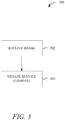
FIG. 3 shows amethod 300 for configuring a service terminal. Themethod 300 may begin atstage 302 where an image of theoptical symbol 110 may be received by thecomputing device 106 from thescanner 102. As disclosed herein, the image may be received during manufacturing of theservice terminal 100, during maintenance, etc. The image may be encoded with component data, such as optical properties, of the top plate, 104, thewindow 108, etc. - From
stage 302, themethod 300 may proceed to stage 304 where a process executed by theservice terminal 100 orcomputing device 106 may be updated. For example, and as disclosed herein, using the image of theoptical symbol 110, thecomputing device 106 may receive optical properties for the window 108 (either directly from theoptical symbol 110 or by retrieving it from a database). Using the optical properties, thecomputing device 106 may update one or more processes or algorithms executed by thecomputing device 106. For instance, the optical properties may indicate a loss associated with an image due to thewindow 108 having a low transmissivity or a color shift due to a tint of thewindow 108. Thus, thecomputing device 106 can add a correction factor or color correction to a second image scanned by thescanner 102 accordingly. - Updating a process executed by the
computing device 106 orservice terminal 100 may include updating software. For example, upon scanning theoptical symbol 110, lines of code or variables used by the code may be replaced and updated. For example, the software may utilize the transmissivity of thewindow 108 and after the scanning of theoptical symbol 110, the transmissivity of thewindow 108 may be saved in thememory 208. - As disclosed herein, the
method 300 can occur at startup of theservice terminal 100, during manufacturing of theservice terminal 100, or when maintenance is performed on theservice terminal 100. In addition, when theoptical symbol 110 is scanned, thecomputing device 106 may also retrieve software updates. For example, after scanning theoptical symbol 110, thecomputing device 106 may access a remote service and download a software update. The software update may be part of regular updates and theoptical symbol 110 may be a pointer to a location where the updates may be found. In addition, the component data identified by theoptical symbol 110 may require additional drivers or other software to make a component function. For example, theoptical symbol 110 may be applied to a scale and during installation of the scale, thescanner 102 may scan theoptical symbol 110 and download drivers for the scale. - The systems and methods disclosed herein address a technical problem and apply a technical solution to the technical problem. The technical problem may be the distortion or other errors introduced during a scanning process by the
window 108. The systems and methods herein allow for any type of material to be used as thewindow 108 and protect thescanner 102 from damage while still allowing thescanner 102 to operate at maximum performance. As a result, the systems and methods disclosed herein result in an increased performance and efficiency of theservice terminal 100 by allowing components to be changed or otherwise altered during the manufacturing of or while performing maintance to theservice terminal 100 without degrading performance. - It will be readily understood to those skilled in the art that various other changes in the details, material, and arrangements of the parts and method stages which have been described and illustrated in order to explain the nature of the inventive subject matter may be made without departing from the principles and scope of the inventive subject matter as expressed in the subjoined claims.
Claims (15)
- A method (300) of configuring a service terminal, the method comprising:reading an optical symbol located on a component of the service terminal using a scanner, the scanner in electrical communication with the service terminal, the optical symbol including data associated with the component (302); andupdating a process executable by the service terminal using the data associated with the component (304).
- The method of claim 1, wherein the data includes optical data for a window associated with the scanner.
- The method of claim 1, wherein the scanner is integrated with the service terminal.
- The method of claim 1, wherein the scanner is a handheld scanner in electrical communication with the service terminal.
- The method of claim 1, wherein the optical symbol is a bar code, a quick response code, or a distinct image.
- The method of claim 1, wherein the data associated with the component is encoded within the optical symbol.
- The method of claim 1, wherein the data associated with the component is a pointer to a location within a database storing configuration data for the component.
- A service terminal (100) comprising:a processor (206); anda memory (208) storing instructions that, when executed by the processor (206), cause the processor to:receive, from a scanner (102), an image of an optical symbol (110), the optical symbol including data associated with a component of the service terminal; andupdate a process executable by the processor using the data associated with the component.
- The system of claim 8, wherein updating the process executable by the processor includes further causing the processor to apply a color correction to a second image received by from the scanner.
- The service terminal of claim 8, wherein the component includes a scanning window and the data includes optical data for the scanning window.
- The service terminal of claim 8, wherein the scanner is integrated with the service terminal.
- The service terminal of claim 8, wherein the scanner is a handheld scanner in electrical communication with the service terminal.
- The service terminal of claim 8, wherein the optical symbol is a bar code, a quick response code, or a distinct image.
- The service terminal of claim 8, wherein the data associated with the component is encoded within the optical symbol.
- The service terminal of claim 8, wherein the data associated with the component is a pointer to a location within a database storing configuration data for the component.
Applications Claiming Priority (1)
| Application Number | Priority Date | Filing Date | Title |
|---|---|---|---|
| US15/472,314 US20180286187A1 (en) | 2017-03-29 | 2017-03-29 | Optical compensation for image scanner |
Publications (2)
| Publication Number | Publication Date |
|---|---|
| EP3396584A2 true EP3396584A2 (en) | 2018-10-31 |
| EP3396584A3 EP3396584A3 (en) | 2018-11-07 |
Family
ID=61683589
Family Applications (1)
| Application Number | Title | Priority Date | Filing Date |
|---|---|---|---|
| EP18161783.8A Withdrawn EP3396584A3 (en) | 2017-03-29 | 2018-03-14 | Optical compensation for image scanner |
Country Status (3)
| Country | Link |
|---|---|
| US (1) | US20180286187A1 (en) |
| EP (1) | EP3396584A3 (en) |
| CN (1) | CN108694787B (en) |
Family Cites Families (9)
| Publication number | Priority date | Publication date | Assignee | Title |
|---|---|---|---|---|
| JP4312469B2 (en) * | 2003-02-21 | 2009-08-12 | 富士通株式会社 | Bar code reader |
| US7617983B1 (en) * | 2004-12-23 | 2009-11-17 | Ncr Corporation | Methods and apparatus for dynamic adjustment of scanner parameters |
| CN101001304A (en) * | 2006-01-09 | 2007-07-18 | 明基电通信息技术有限公司 | Image scanning device and its focus method |
| US7681795B2 (en) * | 2006-03-27 | 2010-03-23 | Ncr Corporation | Methods and apparatus for a scanner having a top plate assembly with weight measurement capabilities |
| US7857222B2 (en) * | 2007-08-16 | 2010-12-28 | Hand Held Products, Inc. | Data collection system having EIR terminal interface node |
| US8770485B1 (en) * | 2013-06-28 | 2014-07-08 | Marson Technology Co., Ltd. | Actuation method of virtual laser barcode scanner |
| GB2518443A (en) * | 2013-09-24 | 2015-03-25 | Ibm | Method for detecting phishing of a matrix barcode |
| US10282187B2 (en) * | 2014-07-03 | 2019-05-07 | Oracle International Corporation | Efficient application patching in heterogeneous computing environments |
| US10769389B2 (en) * | 2014-08-27 | 2020-09-08 | Ncr Corporation | Automatic scanner configuration |
-
2017
- 2017-03-29 US US15/472,314 patent/US20180286187A1/en not_active Abandoned
-
2018
- 2018-03-14 EP EP18161783.8A patent/EP3396584A3/en not_active Withdrawn
- 2018-03-23 CN CN201810245827.7A patent/CN108694787B/en not_active Expired - Fee Related
Non-Patent Citations (1)
| Title |
|---|
| None |
Also Published As
| Publication number | Publication date |
|---|---|
| US20180286187A1 (en) | 2018-10-04 |
| CN108694787B (en) | 2022-01-14 |
| EP3396584A3 (en) | 2018-11-07 |
| CN108694787A (en) | 2018-10-23 |
Similar Documents
| Publication | Publication Date | Title |
|---|---|---|
| US10621634B2 (en) | Application independent DEX/UCS interface | |
| US9189669B2 (en) | Distinctive notice for different symbology information | |
| US9619685B2 (en) | Encoded information reading terminal with replaceable imaging assembly | |
| US7913911B2 (en) | Method for updating indicia readers | |
| US20140166755A1 (en) | Encoded information reading terminal with multiple imaging assemblies | |
| EP2300950B1 (en) | System and method for configuring a scanner | |
| WO2007117885A1 (en) | System and method for configuring a computing device | |
| JP5760022B2 (en) | Product information display device and computer program | |
| US6668293B2 (en) | Auto-registration of scanner | |
| EP2397968B1 (en) | Intelligent optical code reader | |
| US9430690B2 (en) | Optical information reading device | |
| JP2020191086A (en) | Measuring meter/installed equipment information management system, measuring meter/installed equipment information management method and measuring meter/installed equipment information management program | |
| JP2019091501A (en) | Information detection apparatus and information detection program | |
| CN105472249A (en) | Compatible control method and device for camera | |
| CN107180210B (en) | Imaging device for generating high resolution images using sub-pixel shifting and method using the same | |
| US9594843B2 (en) | Identifying an incorrect entry at an imaging checkout terminal | |
| US20200057877A1 (en) | Code symbol reading device and method therefor | |
| US20180286187A1 (en) | Optical compensation for image scanner | |
| US7445143B2 (en) | In-field monitoring and management of data capture systems | |
| US20180063495A1 (en) | Corrected projection perspective distortion | |
| JP6967981B2 (en) | Goods recognition device and product settlement device | |
| US10539454B2 (en) | Method and apparatus for zeroing a weigh scale | |
| US20240242577A1 (en) | Processing system, processing method, and non-transitory storage medium | |
| US11725980B2 (en) | Separated calibration memory storage for a scale and scanner system | |
| EP3089073B1 (en) | Multiple barcode processing apparatus, systems, and methods |
Legal Events
| Date | Code | Title | Description |
|---|---|---|---|
| PUAI | Public reference made under article 153(3) epc to a published international application that has entered the european phase |
Free format text: ORIGINAL CODE: 0009012 |
|
| STAA | Information on the status of an ep patent application or granted ep patent |
Free format text: STATUS: THE APPLICATION HAS BEEN PUBLISHED |
|
| PUAL | Search report despatched |
Free format text: ORIGINAL CODE: 0009013 |
|
| AK | Designated contracting states |
Kind code of ref document: A2 Designated state(s): AL AT BE BG CH CY CZ DE DK EE ES FI FR GB GR HR HU IE IS IT LI LT LU LV MC MK MT NL NO PL PT RO RS SE SI SK SM TR |
|
| AX | Request for extension of the european patent |
Extension state: BA ME |
|
| AK | Designated contracting states |
Kind code of ref document: A3 Designated state(s): AL AT BE BG CH CY CZ DE DK EE ES FI FR GB GR HR HU IE IS IT LI LT LU LV MC MK MT NL NO PL PT RO RS SE SI SK SM TR |
|
| AX | Request for extension of the european patent |
Extension state: BA ME |
|
| RIC1 | Information provided on ipc code assigned before grant |
Ipc: G06K 7/14 20060101AFI20181001BHEP |
|
| STAA | Information on the status of an ep patent application or granted ep patent |
Free format text: STATUS: REQUEST FOR EXAMINATION WAS MADE |
|
| 17P | Request for examination filed |
Effective date: 20190507 |
|
| RBV | Designated contracting states (corrected) |
Designated state(s): AL AT BE BG CH CY CZ DE DK EE ES FI FR GB GR HR HU IE IS IT LI LT LU LV MC MK MT NL NO PL PT RO RS SE SI SK SM TR |
|
| STAA | Information on the status of an ep patent application or granted ep patent |
Free format text: STATUS: EXAMINATION IS IN PROGRESS |
|
| 17Q | First examination report despatched |
Effective date: 20210215 |
|
| STAA | Information on the status of an ep patent application or granted ep patent |
Free format text: STATUS: THE APPLICATION HAS BEEN WITHDRAWN |
|
| 18W | Application withdrawn |
Effective date: 20230126 |