EP3396420B1 - Method and device for determining overall measurement of seismic observation system repeatability - Google Patents
Method and device for determining overall measurement of seismic observation system repeatability Download PDFInfo
- Publication number
- EP3396420B1 EP3396420B1 EP16877673.0A EP16877673A EP3396420B1 EP 3396420 B1 EP3396420 B1 EP 3396420B1 EP 16877673 A EP16877673 A EP 16877673A EP 3396420 B1 EP3396420 B1 EP 3396420B1
- Authority
- EP
- European Patent Office
- Prior art keywords
- observation system
- shot
- baseline
- receiver pairs
- monitor
- Prior art date
- Legal status (The legal status is an assumption and is not a legal conclusion. Google has not performed a legal analysis and makes no representation as to the accuracy of the status listed.)
- Active
Links
Images

Classifications
-
- G—PHYSICS
- G01—MEASURING; TESTING
- G01V—GEOPHYSICS; GRAVITATIONAL MEASUREMENTS; DETECTING MASSES OR OBJECTS; TAGS
- G01V1/00—Seismology; Seismic or acoustic prospecting or detecting
- G01V1/28—Processing seismic data, e.g. for interpretation or for event detection
- G01V1/30—Analysis
-
- G—PHYSICS
- G01—MEASURING; TESTING
- G01V—GEOPHYSICS; GRAVITATIONAL MEASUREMENTS; DETECTING MASSES OR OBJECTS; TAGS
- G01V1/00—Seismology; Seismic or acoustic prospecting or detecting
- G01V1/28—Processing seismic data, e.g. for interpretation or for event detection
- G01V1/30—Analysis
- G01V1/308—Time lapse or 4D effects, e.g. production related effects to the formation
-
- G—PHYSICS
- G01—MEASURING; TESTING
- G01V—GEOPHYSICS; GRAVITATIONAL MEASUREMENTS; DETECTING MASSES OR OBJECTS; TAGS
- G01V1/00—Seismology; Seismic or acoustic prospecting or detecting
- G01V1/003—Seismic data acquisition in general, e.g. survey design
-
- G—PHYSICS
- G01—MEASURING; TESTING
- G01V—GEOPHYSICS; GRAVITATIONAL MEASUREMENTS; DETECTING MASSES OR OBJECTS; TAGS
- G01V2200/00—Details of seismic or acoustic prospecting or detecting in general
- G01V2200/10—Miscellaneous details
- G01V2200/14—Quality control
-
- G—PHYSICS
- G01—MEASURING; TESTING
- G01V—GEOPHYSICS; GRAVITATIONAL MEASUREMENTS; DETECTING MASSES OR OBJECTS; TAGS
- G01V2210/00—Details of seismic processing or analysis
- G01V2210/10—Aspects of acoustic signal generation or detection
- G01V2210/14—Signal detection
-
- G—PHYSICS
- G01—MEASURING; TESTING
- G01V—GEOPHYSICS; GRAVITATIONAL MEASUREMENTS; DETECTING MASSES OR OBJECTS; TAGS
- G01V2210/00—Details of seismic processing or analysis
- G01V2210/10—Aspects of acoustic signal generation or detection
- G01V2210/16—Survey configurations
-
- G—PHYSICS
- G01—MEASURING; TESTING
- G01V—GEOPHYSICS; GRAVITATIONAL MEASUREMENTS; DETECTING MASSES OR OBJECTS; TAGS
- G01V2210/00—Details of seismic processing or analysis
- G01V2210/60—Analysis
- G01V2210/61—Analysis by combining or comparing a seismic data set with other data
- G01V2210/612—Previously recorded data, e.g. time-lapse or 4D
Definitions
- the present invention relates to the technical field of oil exploration, especially relates to a method and device for determining overall metrics of seismic geometry repeatability.
- time-lapse seismic technology comprehensively interprets the change of oil reservoir differences by using seismic data before and after a period in combination with the data of seismic survey, development and well logging, etc., to obtain main distribution areas of remaining oil, guide adjustments of oil reservoir development solutions, recognize positions of remaining oil among wells, and improve the oil and gas recovery rate. Therefore, in the oil reservoir management, the time-lapse seismic technology plays an important role.
- US20090290449A1 relates to Processing Seismic Data Using Combined Regularization and 4D Binning.
- US20090290449A1 teaches that a combined four-dimensional (4D) binning and regularization procedure is performed on the seismic data, where the combined 4D binning and regularization procedure includes computing measures associated with regularization of the seismic data, computing measures associated with 4D binning, and processing the seismic data according to the regularization measures and 4D binning measures.
- Simultaneous Multi-Vintage 4D Binning by Ehsan Zabihi Naeini , et al. relates to 4D binning as a processing step to improve the repeatability of time-lapse (4D) data.
- a simultaneous multi-vintage (SMV) 4D binning algorithm is introduced which obtains the best possible repeatability across all vintages and in each bin.
- the embodiments of the present invention provide a method and device for determining overall metrics of seismic geometry repeatability, so as to achieve the aim of accurately determining repeatability of multiple shot-receiver pairs in time-lapse seismic acquisition.
- the embodiments of the present invention provide a method for determining overall metrics of seismic observation system geometry repeatability, comprising: selecting a baseline observation system and a monitor observation system within a predetermined range of observation system; matching a plurality of shot-receiver pairs of the baseline observation system with a plurality of shot-receiver pairs of the monitor observation system to obtain multiple matching relationships; calculating overall geometry repeatability of each of the multiple matching relationships, respectively, according to a predetermined calculation formula for multi-trace geometry repeatability, to obtain overall geometry repeatabilities corresponding to the multiple matching relationships; and taking the minimum value among the overall geometry repeatabilities corresponding to the multiple matching relationships as overall geometry repeatability metrics between the monitor observation system and the baseline observation system.
- the step of matching the shot-receiver pairs of the baseline observation system with the shot-receiver pairs of the monitor observation system to obtain the multiple matching relationships comprises: counting the number of shot-receiver pairs of the baseline observation system and the number of shot-receiver pairs of the monitor observation system; and matching the shot-receiver pairs of the baseline observation system with the shot-receiver pairs of the monitor observation system, according to the counting result of the number of shot-receiver pairs of the baseline observation system and the number of shot-receiver pairs of the monitor observation system, to obtain the multiple matching relationships.
- the step of matching the shot-receiver pairs of the baseline observation system with the shot-receiver pairs of the monitor observation system according to the counting result of the number of shot-receiver pairs of the baseline observation system and the number of shot-receiver pairs of the monitor observation system to obtain the multiple matching relationships comprises: when the number of shot-receiver pairs of the monitor observation system is larger than the number of shot-receiver pairs of the baseline observation system, discarding unmatched remaining shot-receiver pairs of the monitor observation system after matching; and when the number of shot-receiver pairs of the monitor observation system is smaller than the number of shot-receiver pairs of the baseline observation system, assigning a predetermined value to each of one or more shot-receiver pairs of the baseline observation system remained unmatched after matching as geometry repeatability between each of the one or more shot-receiver pairs of the baseline observation system and a corresponding shot-receiver pair of the monitor observation system.
- the step of selecting the baseline observation system and the monitor observation system within the predetermined range of observation system comprises: selecting the baseline observation system and the monitor observation system according to a bin in which the mid points locate and according to an offset range; or selecting the baseline observation system and the monitor observation system according to a bin in which the reflection points locate and according to an offset range.
- the embodiments of the present invention further provide a device for determining overall metrics of observation system seismic geometry repeatability, comprising: a selection module for selecting baseline observation system and a monitor observation system within a predetermined range of observation system; a matching module for matching a plurality of shot-receiver pairs of the baseline observation system with a plurality of shot-receiver pairs of the monitor observation system to obtain multiple matching relationships; a calculation module for calculating overall geometry repeatability of each of the multiple matching relationships, respectively, according to a predetermined calculation formula for multi-trace geometry repeatability, to obtain overall geometry repeatabilities corresponding to the multiple matching relationships; and a metrics module for taking the minimum value among the overall geometry repeatabilities corresponding to the multiple matching relationships as overall geometry repeatability metrics between the monitor observation system and the baseline observation system.
- the matching module comprises: a number counting unit for counting the number of shot-receiver pairs of the baseline observation system and the number of shot-receiver pairs of the monitor observation system; and a relationship matching unit for matching the shot-receiver pairs of the baseline observation system with the shot-receiver pairs of the monitor observation system, according to the counting result of the number of shot-receiver pairs of the baseline observation system and the number of shot-receiver pairs of the monitor observation system, to obtain the multiple matching relationships.
- the relationship matching unit comprises: a discarding subunit for discarding unmatched remaining shot-receiver pairs of the monitor observation system after matching when the number of shot-receiver pairs of the monitor observation system is larger than the number of shot-receiver pairs of the baseline observation system; and an assigning subunit for assigning a predetermined value to each of one or more shot-receiver pairs of the baseline observation system remained unmatched after matching as geometry repeatability between each of the one or more shot-receiver pairs of the baseline observation system and a corresponding shot-receiver pair of the monitor observation system when the number of shot-receiver pairs of the monitor observation system is smaller than the number of shot-receiver pairs of the baseline observation system.
- the selection module comprises: a first selection unit for selecting the baseline observation system and the monitor observation system according to a bin in which the mid points locate and according to an offset range; or a second selection unit for selecting the baseline observation system and the monitor observation system according to a bin in which the reflection points locate and according to an offset range.
- baseline observation system and monitor observation system are selected within a predetermined range of observation system firstly, then a plurality of shot-receiver pairs of the baseline observation system and a plurality of shot-receiver pairs of the monitor observation system are matched with each other to obtain multiple matching relationships, then calculations are conducted for the above multiple matching relationships respectively, according to a calculation formula for multi-trace geometry repeatability, so that overall geometry repeatability corresponding to each of the multiple matching relationships can be obtained.
- the minimum value among the corresponding repeatabilities is taken as overall geometry repeatability metrics between the monitor observation system and the baseline observation system.
- the situation of different number and uncertain matching of shot-receiver pairs between the baseline observation system and the monitor observation system can be solved, and the aim of accurately determining repeatability of multiple shot-receiver pairs in time-lapse seismic acquisition can be achieved.
- baseline observation system and monitor observation system may be selected according to a bin in which the mid points locate and according to an offset range; or baseline observation system and monitor observation system can be selected according to a bin in which the reflection points locate and according to an offset range.
- Step 102 matching a plurality of shot-receiver pairs of the baseline observation system with a plurality of shot-receiver pairs of the monitor observation system to obtain multiple matching relationships;
- a repeatability evaluation can be performed on multiple shot-receiver pairs in the seismic acquisition.
- matching shot-receiver pairs of the baseline observation system with shot-receiver pairs of the monitor observation system may comprise the following steps:
- the following two situations may occur: when the number of shot-receiver pairs of the monitor observation system is larger than the number of shot-receiver pairs of the baseline observation system, remaining unmatched shot-receiver pairs of the monitor observation system can be discarded after matching; when the number of shot-receiver pairs of the monitor observation system is smaller than the number of shot-receiver pairs of the baseline observation system, if there is no corresponding shot-receiver pairs in the monitor observation system corresponding to shot-receiver pairs in the baseline observation system, a predetermined value for each of one or more shot-receiver pairs of the baseline observation system remained after matching can be assigned, as geometry repeatability between each of the one or more shot-receiver pairs of the baseline observation system and the corresponding shot-receiver pair of the monitor observation system.
- shot-receiver pairs in the above example are only a schematic description, and in actual implementation, there may be other amount of shot-receiver pairs, such as six or ten, etc., and the specific amount of shot-receiver pairs is not limited in the present invention.
- Step 103 calculating overall geometry repeatability of each of the multiple matching relationships according to a predetermined calculation formula for multi-trace geometry repeatability, respectively, to obtain overall geometry repeatabilities corresponding to the multiple matching relationships;
- the repeatability of geometry can be represented as a sum of geometry's shot point deviation and receiver point deviation, but in this embodiment, the repeatability of geometry can be represented as the distance between a shot point of the monitor observation system and a shot point of the baseline observation system plus the distance between a receiver point of the monitor observation system and a receiver point of the baseline observation system.
- a predetermined calculation formula for multi-trace geometry repeatability is applied to calculate overall geometry repeatability of each of the obtained multiple matching relationships, respectively.
- the weighting coefficient k ( x i ) keeps the same during the calculation of repeatability of the current matching relationship and during the comparison of overall geometry repeatability.
- Step 104 taking the minimum value among the overall geometry repeatabilities corresponding to the multiple matching relationships as overall geometry repeatability metrics between the monitor observation system and the baseline observation system;
- a specific invention example of the method for determining overall repeatability metrics of seismic geometry is described below.
- the repeatability of geometry corresponding to each Common Mid Point (referred as CMP) bin into which the mid points fall in a certain area is calculated by using the above method for determining overall repeatability metrics of seismic geometry.
- CMP Common Mid Point
- calculating the repeatability of geometry corresponding to each CMP bin into which the mid points fall by using the above method for determining overall metrics of seismic geometry repeatability may comprise the following steps:
- Step 204 taking the minimum value among the overall geometry repeatabilities corresponding to the multiple matching relationships as overall repeatability metrics between the monitor observation system and the baseline observation system.
- FIG. 4 shows a schematic diagram for calculating repeatability of the above geometry by adopting the method for determining overall metrics of seismic geometry repeatability.
- a device for determining overall metrics of observation system seismic geometry repeatability is also provided in embodiments of the present invention, as described in the following embodiments. Since the principle for solving problems by the device for determining overall metrics of seismic geometry repeatability is similar to that of the method for determining overall metrics of seismic geometry repeatability, thus the implementation of the device for determining overall metrics of seismic geometry repeatability may refer to the implementation of the method for determining overall metrics of seismic geometry repeatability, and thus repetitive parts will be omitted. As used below, the terms "unit” or “module” may realize combination of software and/or hardware with predetermined functions. Although the device described in the following embodiments is preferably implemented by software, implementation through hardware or the combination of software and hardware may also be conceived.
- FIG. 5 is a structural block diagram of a device for determining overall metrics of seismic geometry repeatability in an embodiment of the present invention. As shown in FIG. 5 , the device includes a selection module 501, a matching module 502, a calculation module 503 and a metrics module 504, which are explained below.
- the selection module 501 is used for selecting baseline observation system and monitor observation system within a predetermined range of observation system
- the matching module includes: a number counting unit for counting the number of shot-receiver pairs of the baseline observation system and the number of shot-receiver pairs of the monitor observation system; a relationship matching unit for matching shot-receiver pairs of the baseline observation system with shot-receiver pairs of the monitor observation system according to the counting result of the number of shot-receiver pairs of the baseline observation system and the number of shot-receiver pairs of the monitor observation system to obtain multiple matching relationships.
- the relationship matching unit includes: a discarding subunit for discarding remaining unmatched shot-receiver pairs of the monitor observation system after matching when the number of shot-receiver pairs of the monitor observation system is larger than the number of shot-receiver pairs of the baseline observation system; an assigning subunit for assigning a predetermined value to each of one or more shot-receiver pairs of the baseline observation system remained unmatched after matching as geometry repeatability between each of the one or more shot-receiver pairs of the baseline observation system and the corresponding shot-receiver pair of the monitor observation system.
- the selection module includes: a first selection unit for selecting baseline observation system and monitor observation system according to a bin in which the mid points locate and an offset range; or a second selection unit for selecting baseline observation system and monitor observation system based on a bin in which the reflection points locate and an offset range.
- the embodiments of the present invention realize the following technical effects: during the calculation of seismic geometry repeatability, firstly, baseline observation system and monitor observation system are selected within a predetermined range of observation system, then shot-receiver pairs of the baseline observation system and shot-receiver pairs of the monitor observation system are matched with each other to obtain multiple matching relationships, then calculations are conducted for the above multiple matching relationships, respectively, according to a calculation formula for multi-trace geometry repeatability, so that overall geometry repeatability corresponding to each of the multiple matching relationships can be obtained, the minimum value among the corresponding repeatabilities is taken as overall repeatability metrics between the monitor observation system and the baseline observation system.
- the situation of different number and uncertain matching of shot-receiver pairs between the baseline observation system and the monitor observation system can be solved, the aim of accurately determining repeatability of multiple shot-receiver pairs in time-lapse seismic acquisition can be achieved, and thus the monitoring efficiency of seismic geometry repeatability can be improved.
- the respective modules or the steps in the above mentioned embodiments of the present invention can be implemented by using a universal computing device, they may be centralized on a single computing device or distributed on a network consisting of a plurality of computing devices, and alternatively, they may be implemented by using program codes that may be executed by computing devices, so that they may be stored in the storage device to be executed by computing devices, and in some circumstances, the steps as shown or described may be performed in an order different from that described herein, or they may be fabricated as various integrated circuit module, respectively, or multiple modules or steps therein may be fabricated as a single integrated circuit module. In this way, the embodiments of the present invention are not limited to any specific combination of hardware and software.
Landscapes
- Physics & Mathematics (AREA)
- Engineering & Computer Science (AREA)
- Remote Sensing (AREA)
- Life Sciences & Earth Sciences (AREA)
- Acoustics & Sound (AREA)
- Environmental & Geological Engineering (AREA)
- Geology (AREA)
- General Life Sciences & Earth Sciences (AREA)
- General Physics & Mathematics (AREA)
- Geophysics (AREA)
- Fluid Mechanics (AREA)
- Geophysics And Detection Of Objects (AREA)
Description
- This application claims priority to
Chinese Patent Application No. 201510993665.1, filed on December 25, 2015 - The present invention relates to the technical field of oil exploration, especially relates to a method and device for determining overall metrics of seismic geometry repeatability.
- Currently, many old oil fields have entered the middle and later stages of development, fluid distribution and oil reservoir development within rocks are complex, the average value of oil recovery rate is low, and thus a large amount of remaining oil exists. The time-lapse seismic technology comprehensively interprets the change of oil reservoir differences by using seismic data before and after a period in combination with the data of seismic survey, development and well logging, etc., to obtain main distribution areas of remaining oil, guide adjustments of oil reservoir development solutions, recognize positions of remaining oil among wells, and improve the oil and gas recovery rate. Therefore, in the oil reservoir management, the time-lapse seismic technology plays an important role.
-
US20090290449A1 relates to Processing Seismic Data Using Combined Regularization and 4D Binning. To process seismic data,US20090290449A1 teaches that a combined four-dimensional (4D) binning and regularization procedure is performed on the seismic data, where the combined 4D binning and regularization procedure includes computing measures associated with regularization of the seismic data, computing measures associated with 4D binning, and processing the seismic data according to the regularization measures and 4D binning measures. - " Simultaneous Multi-Vintage 4D Binning" by Ehsan Zabihi Naeini, et al. relates to 4D binning as a processing step to improve the repeatability of time-lapse (4D) data. In the paper, a simultaneous multi-vintage (SMV) 4D binning algorithm is introduced which obtains the best possible repeatability across all vintages and in each bin.
- The key to the success of the time-lapse seismic technology lies in repeatability, thus an effective method for repeatability metrics and consistency analysis of time-lapse seismic data is needed. In the time-lapse seismic acquisition in an offshore streamer mode, existing techniques for evaluating seismic geometry repeatability have shot point deviation evaluation, feather angle deviation evaluation, azimuth deviation evaluation and repeatability evaluation for a single offset. Wherein, the shot point deviation evaluation, the feather angle deviation evaluation or the azimuth deviation evaluation is performed for partial components therein when performing the repeatability evaluation on the geometry; while as for the repeatability evaluation for a single offset, although it is performed for whole components, only a single shot-receiver pair therein is evaluated, and for the case of multiple shot-receiver pairs, currently, no specific method for determining repeatability has been disclosed. However, before proposing techniques in the present invention, the inventor Fengshu DONG has carried out a systematical and theoretical study on multi-trace repeatability and formed a theory, meanwhile he has planned to disclose and publish the studied theory, which realizes disclosing and publish the theory after the priority date of the present invention (Fengshu DONG, 2016, RESEARCH ON SURVEY REPEATABILITY IN TIME-LAPSE SEISMIC [PhD thesis], Beijing: University of Chinese Academy of Sciences, Institute of Geology and Geophysics, Chinese Academy of Sciences; Fengshu DONG, Liyun FU, Haiyan QUAN et al, 2016, MATCHED MULTI-TRACE GEOMETRY REPEATABILITY FOR TIME LAPSE SEISMIC, Chinese Journal of Geophysics, 59(8) : 3056-3067, doi : 10.6038/cjg20160828 ; Feng-Shu, D., Li-Yun, F., Hai-Yan, Q., Ke-Tong, D. and Xiu-Yan, X. (2016), MATCHED MULTI-TRACE WEIGHTED RMS GEOMETRY REPEATABILITY FOR TIME-LAPSE SEISMIC. Chinese Journal of Geophysics, 59: 442-456. doi:10.1002/cjg2.20248).
- As for the above problem of how to determine repeatability of multiple shot-receiver pairs in seismic acquisition, currently, no effective solution has been proposed publicly. The present invention is completed based on the above theory, and the reasonability of the invention is supported by this theory.
- The embodiments of the present invention provide a method and device for determining overall metrics of seismic geometry repeatability, so as to achieve the aim of accurately determining repeatability of multiple shot-receiver pairs in time-lapse seismic acquisition.
- The embodiments of the present invention provide a method for determining overall metrics of seismic observation system geometry repeatability, comprising: selecting a baseline observation system and a monitor observation system within a predetermined range of observation system; matching a plurality of shot-receiver pairs of the baseline observation system with a plurality of shot-receiver pairs of the monitor observation system to obtain multiple matching relationships; calculating overall geometry repeatability of each of the multiple matching relationships, respectively, according to a predetermined calculation formula for multi-trace geometry repeatability, to obtain overall geometry repeatabilities corresponding to the multiple matching relationships; and taking the minimum value among the overall geometry repeatabilities corresponding to the multiple matching relationships as overall geometry repeatability metrics between the monitor observation system and the baseline observation system.
- In an embodiment, the predetermined calculation formula for multi-trace geometry repeatability is expressed as:

- In an embodiment, the step of matching the shot-receiver pairs of the baseline observation system with the shot-receiver pairs of the monitor observation system to obtain the multiple matching relationships comprises: counting the number of shot-receiver pairs of the baseline observation system and the number of shot-receiver pairs of the monitor observation system; and matching the shot-receiver pairs of the baseline observation system with the shot-receiver pairs of the monitor observation system, according to the counting result of the number of shot-receiver pairs of the baseline observation system and the number of shot-receiver pairs of the monitor observation system, to obtain the multiple matching relationships.
- In an embodiment, the step of matching the shot-receiver pairs of the baseline observation system with the shot-receiver pairs of the monitor observation system according to the counting result of the number of shot-receiver pairs of the baseline observation system and the number of shot-receiver pairs of the monitor observation system to obtain the multiple matching relationships comprises: when the number of shot-receiver pairs of the monitor observation system is larger than the number of shot-receiver pairs of the baseline observation system, discarding unmatched remaining shot-receiver pairs of the monitor observation system after matching; and when the number of shot-receiver pairs of the monitor observation system is smaller than the number of shot-receiver pairs of the baseline observation system, assigning a predetermined value to each of one or more shot-receiver pairs of the baseline observation system remained unmatched after matching as geometry repeatability between each of the one or more shot-receiver pairs of the baseline observation system and a corresponding shot-receiver pair of the monitor observation system.
- In an embodiment, the step of selecting the baseline observation system and the monitor observation system within the predetermined range of observation system comprises: selecting the baseline observation system and the monitor observation system according to a bin in which the mid points locate and according to an offset range; or selecting the baseline observation system and the monitor observation system according to a bin in which the reflection points locate and according to an offset range.
- The embodiments of the present invention further provide a device for determining overall metrics of observation system seismic geometry repeatability, comprising: a selection module for selecting baseline observation system and a monitor observation system within a predetermined range of observation system; a matching module for matching a plurality of shot-receiver pairs of the baseline observation system with a plurality of shot-receiver pairs of the monitor observation system to obtain multiple matching relationships; a calculation module for calculating overall geometry repeatability of each of the multiple matching relationships, respectively, according to a predetermined calculation formula for multi-trace geometry repeatability, to obtain overall geometry repeatabilities corresponding to the multiple matching relationships; and a metrics module for taking the minimum value among the overall geometry repeatabilities corresponding to the multiple matching relationships as overall geometry repeatability metrics between the monitor observation system and the baseline observation system.
- In an embodiment, the calculation module is further configured to calculate for the multi-trace geometry repeatability according to the following predetermined formula:

- In an embodiment, the matching module comprises: a number counting unit for counting the number of shot-receiver pairs of the baseline observation system and the number of shot-receiver pairs of the monitor observation system; and a relationship matching unit for matching the shot-receiver pairs of the baseline observation system with the shot-receiver pairs of the monitor observation system, according to the counting result of the number of shot-receiver pairs of the baseline observation system and the number of shot-receiver pairs of the monitor observation system, to obtain the multiple matching relationships.
- In an embodiment, the relationship matching unit comprises: a discarding subunit for discarding unmatched remaining shot-receiver pairs of the monitor observation system after matching when the number of shot-receiver pairs of the monitor observation system is larger than the number of shot-receiver pairs of the baseline observation system; and an assigning subunit for assigning a predetermined value to each of one or more shot-receiver pairs of the baseline observation system remained unmatched after matching as geometry repeatability between each of the one or more shot-receiver pairs of the baseline observation system and a corresponding shot-receiver pair of the monitor observation system when the number of shot-receiver pairs of the monitor observation system is smaller than the number of shot-receiver pairs of the baseline observation system.
- In an embodiment, the selection module comprises: a first selection unit for selecting the baseline observation system and the monitor observation system according to a bin in which the mid points locate and according to an offset range; or a second selection unit for selecting the baseline observation system and the monitor observation system according to a bin in which the reflection points locate and according to an offset range.
- In the embodiments of the present invention, during the calculation of seismic geometry repeatability, baseline observation system and monitor observation system are selected within a predetermined range of observation system firstly, then a plurality of shot-receiver pairs of the baseline observation system and a plurality of shot-receiver pairs of the monitor observation system are matched with each other to obtain multiple matching relationships, then calculations are conducted for the above multiple matching relationships respectively, according to a calculation formula for multi-trace geometry repeatability, so that overall geometry repeatability corresponding to each of the multiple matching relationships can be obtained. The minimum value among the corresponding repeatabilities is taken as overall geometry repeatability metrics between the monitor observation system and the baseline observation system. By using the above method, the situation of different number and uncertain matching of shot-receiver pairs between the baseline observation system and the monitor observation system can be solved, and the aim of accurately determining repeatability of multiple shot-receiver pairs in time-lapse seismic acquisition can be achieved.
- Accompanying drawings described here, which serve to provide further understanding of the present invention, constitute a part of the present invention, but do not constitute the limitation to the present invention. In the drawings:
-
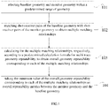
FIG. 1 is a flow chart of a method for determining overall metrics of seismic geometry repeatability in an embodiment of the present invention; -
FIG. 2 is a flow chart of calculating repeatability of a geometry corresponding to each CMP bin into which the mid points fall, according to the method for determining overall metrics of seismic geometry repeatability in an embodiment of the present invention; -
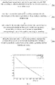
FIG. 3 is a schematic graph of a weighting coefficient varying with the offset in an embodiment of the present invention; -
FIG. 4 is a schematic diagram of calculating repeatability of a geometry corresponding to each CMP bin into which the mid points fall by using the method for determining overall metrics of seismic geometry repeatability in an embodiment of the present invention; and -
FIG. 5 is a structural block diagram of determining overall metrics of seismic geometry repeatability in an embodiment of the present invention. - In order to make the purposes, technical solutions and advantages of the present invention more clearly, the present invention is further described in detail as follows in combination with embodiments and the accompanying drawings. Here, the schematic embodiments of the present invention and description thereof are intended to explain the present invention, but are not intended to limit the present invention.
- Considering when evaluating seismic geometry repeatability, if an accurate evaluation result is required to be obtained, the number of shot-receiver pairs which participate in the repeatability evaluation needs to be increased greatly; if the number of shot-receiver pairs is too small, it is impossible to provide a reliable evaluation for a seismic geometry. Specifically, it provides a method for determining overall metrics of seismic observation system geometry repeatability in this example, as shown in
FIG. 1 , which may comprise the following steps: - Step 101: selecting baseline observation system and monitor observation system within a predetermined range of observation system;
- For a seismic system, in particular for a time-lapse seismic system, when acquiring seismic data, acquisition needs to be conducted for seismic systems in different situations. Wherein, data obtained from the first acquisition is referred to as baseline seismic data; data, obtained from the acquisition performed again according to demands after experiencing a period of human intervention, is referred to as monitored seismic data. Through multiple explorations, it may obtain seismic data for exploration targets at different time and know differences of seismic data for exploration targets at different time, thereby the effect of human intervention, such as oil and gas exploitation, to an exploration target may be obtained.
- Specifically, in this embodiment, baseline observation system and monitor observation system may be selected according to a bin in which the mid points locate and according to an offset range; or baseline observation system and monitor observation system can be selected according to a bin in which the reflection points locate and according to an offset range.
- Step 102: matching a plurality of shot-receiver pairs of the baseline observation system with a plurality of shot-receiver pairs of the monitor observation system to obtain multiple matching relationships;
In this embodiment, by matching shot-receiver pairs of the baseline observation system with shot-receiver pairs of the monitor observation system, a repeatability evaluation can be performed on multiple shot-receiver pairs in the seismic acquisition. Specifically, matching shot-receiver pairs of the baseline observation system with shot-receiver pairs of the monitor observation system may comprise the following steps: - SI: counting the number of shot-receiver pairs of the baseline observation system and the number of shot-receiver pairs of the monitor observation system, respectively;
- S2: matching shot-receiver pairs of the baseline observation system with shot-receiver pairs of the monitor observation system, according to the counting result of the number of shot-receiver pairs of the baseline observation system and the number of shot-receiver pairs of the monitor observation system, to obtain multiple matching relationships.
- When matching shot-receiver pairs of the baseline observation system with shot-receiver pairs of the monitor observation system, the following two situations may occur: when the number of shot-receiver pairs of the monitor observation system is larger than the number of shot-receiver pairs of the baseline observation system, remaining unmatched shot-receiver pairs of the monitor observation system can be discarded after matching; when the number of shot-receiver pairs of the monitor observation system is smaller than the number of shot-receiver pairs of the baseline observation system, if there is no corresponding shot-receiver pairs in the monitor observation system corresponding to shot-receiver pairs in the baseline observation system, a predetermined value for each of one or more shot-receiver pairs of the baseline observation system remained after matching can be assigned, as geometry repeatability between each of the one or more shot-receiver pairs of the baseline observation system and the corresponding shot-receiver pair of the monitor observation system.
- Accordingly, after performing the matching according to the counting result of the number of shot-receiver pairs of the baseline observation system and the number of shot-receiver pairs of the monitor observation system, multiple matching relationships can be obtained.
- For example, when the number of shot-receiver pairs of the monitor observation system is five and the number of shot-receiver pairs of the baseline observation system is three, after matching three shot-receiver pairs of the baseline observation system with three shot-receiver pairs of the monitor observation system, the remaining two shot-receiver pairs of the monitor observation system are discarded, and finally 5×4×3=60 matching relationships can be obtained; when the number of shot-receiver pairs of the monitor observation system is four and the number of shot-receiver pairs of the baseline observation system is five, after matching four shot-receiver pairs of the baseline observation system with four shot-receiver pairs of the monitor observation system, one shot-receiver pair of the baseline observation system is remained, a predetermined value is assigned as the repeatability between the remaining one shot-receiver pair of the baseline observation system and the corresponding shot-receiver pair of the monitor observation system, and finally 5×4×3×2×1=120 matching relationships can be obtained.
- However, it should be noted that five shot-receiver pairs in the above example are only a schematic description, and in actual implementation, there may be other amount of shot-receiver pairs, such as six or ten, etc., and the specific amount of shot-receiver pairs is not limited in the present invention.
- Step 103: calculating overall geometry repeatability of each of the multiple matching relationships according to a predetermined calculation formula for multi-trace geometry repeatability, respectively, to obtain overall geometry repeatabilities corresponding to the multiple matching relationships;
Studies show that the repeatability of geometry obviously affects the repeatability of time-lapse seismic data. The repeatability of geometry can be represented as a sum of geometry's shot point deviation and receiver point deviation, but in this embodiment, the repeatability of geometry can be represented as the distance between a shot point of the monitor observation system and a shot point of the baseline observation system plus the distance between a receiver point of the monitor observation system and a receiver point of the baseline observation system. Specifically, the repeatability of seismic waveform data can be calculated by normalizing a mean square root of difference data between two sets of seismic data in a given time window, the calculation formula is as follows:
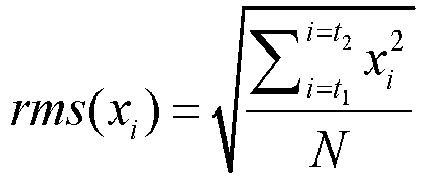
- Further, a predetermined calculation formula for multi-trace geometry repeatability is applied to calculate overall geometry repeatability of each of the obtained multiple matching relationships, respectively. The calculation formula for overall geometry repeatability can be expressed as:

- In the above formula, the weighting coefficient k(xi ) keeps the same during the calculation of repeatability of the current matching relationship and during the comparison of overall geometry repeatability.
- After the above calculation, the overall geometry repeatability corresponding to each of the multiple matching relationships can be obtained.
- Step 104: taking the minimum value among the overall geometry repeatabilities corresponding to the multiple matching relationships as overall geometry repeatability metrics between the monitor observation system and the baseline observation system;
A specific invention example of the method for determining overall repeatability metrics of seismic geometry is described below. In this embodiment, the repeatability of geometry corresponding to each Common Mid Point (referred as CMP) bin into which the mid points fall in a certain area is calculated by using the above method for determining overall repeatability metrics of seismic geometry. However, it should be noted that this specific embodiment is only for better explaining the present invention, but does not constitute improper limitation to the present invention. - As shown in
FIG. 2 , calculating the repeatability of geometry corresponding to each CMP bin into which the mid points fall by using the above method for determining overall metrics of seismic geometry repeatability may comprise the following steps: - Step 201: selecting baseline observation system and monitor observation system of each CMP bin according to a bin in which the mid points locate and according to an offset range;
- Step 202: matching shot-receiver pairs of the baseline observation system with shot-receiver pairs of the monitor observation system to obtain multiple matching relationships;
- Step 203: calculating overall geometry repeatability of each of the multiple matching relationships, according to a predetermined calculation formula for multi-trace geometry repeatability, to obtain overall geometry repeatabilities corresponding to the multiple matching relationships;
- Step 204: taking the minimum value among the overall geometry repeatabilities corresponding to the multiple matching relationships as overall repeatability metrics between the monitor observation system and the baseline observation system.
-
FIG. 4 shows a schematic diagram for calculating repeatability of the above geometry by adopting the method for determining overall metrics of seismic geometry repeatability. - Based on the same inventive concept, a device for determining overall metrics of observation system seismic geometry repeatability is also provided in embodiments of the present invention, as described in the following embodiments. Since the principle for solving problems by the device for determining overall metrics of seismic geometry repeatability is similar to that of the method for determining overall metrics of seismic geometry repeatability, thus the implementation of the device for determining overall metrics of seismic geometry repeatability may refer to the implementation of the method for determining overall metrics of seismic geometry repeatability, and thus repetitive parts will be omitted. As used below, the terms "unit" or "module" may realize combination of software and/or hardware with predetermined functions. Although the device described in the following embodiments is preferably implemented by software, implementation through hardware or the combination of software and hardware may also be conceived. For example, the device can be implemented by a computer.
FIG. 5 is a structural block diagram of a device for determining overall metrics of seismic geometry repeatability in an embodiment of the present invention. As shown inFIG. 5 , the device includes aselection module 501, amatching module 502, acalculation module 503 and ametrics module 504, which are explained below. - The
selection module 501 is used for selecting baseline observation system and monitor observation system within a predetermined range of observation system; - The
matching module 502 is used for matching a plurality of shot-receiver pairs of the baseline observation system with a plurality of shot-receiver pairs of the monitor observation system to obtain multiple matching relationships; - The
calculation module 503 is used for calculating overall geometry repeatability of each of the multiple matching relationships, according to a predetermined calculation formula for multi-trace geometry repeatability, respectively, to obtain overall geometry repeatabilities corresponding to the multiple matching relationships; - The
metrics module 504 is used for taking the minimum value among the overall geometry repeatabilities corresponding to the multiple matching relationships as overall geometry repeatability metrics between the monitor observation system and the baseline observation system. - In an embodiment, the calculation module is further configured to calculate the multi-trace geometry repeatability according to the following predetermined formula:

- In an embodiment, the matching module includes: a number counting unit for counting the number of shot-receiver pairs of the baseline observation system and the number of shot-receiver pairs of the monitor observation system; a relationship matching unit for matching shot-receiver pairs of the baseline observation system with shot-receiver pairs of the monitor observation system according to the counting result of the number of shot-receiver pairs of the baseline observation system and the number of shot-receiver pairs of the monitor observation system to obtain multiple matching relationships.
- In an embodiment, the relationship matching unit includes: a discarding subunit for discarding remaining unmatched shot-receiver pairs of the monitor observation system after matching when the number of shot-receiver pairs of the monitor observation system is larger than the number of shot-receiver pairs of the baseline observation system; an assigning subunit for assigning a predetermined value to each of one or more shot-receiver pairs of the baseline observation system remained unmatched after matching as geometry repeatability between each of the one or more shot-receiver pairs of the baseline observation system and the corresponding shot-receiver pair of the monitor observation system.
- In an embodiment, the selection module includes: a first selection unit for selecting baseline observation system and monitor observation system according to a bin in which the mid points locate and an offset range; or a second selection unit for selecting baseline observation system and monitor observation system based on a bin in which the reflection points locate and an offset range.
- As can be seen from the above description, the embodiments of the present invention realize the following technical effects: during the calculation of seismic geometry repeatability, firstly, baseline observation system and monitor observation system are selected within a predetermined range of observation system, then shot-receiver pairs of the baseline observation system and shot-receiver pairs of the monitor observation system are matched with each other to obtain multiple matching relationships, then calculations are conducted for the above multiple matching relationships, respectively, according to a calculation formula for multi-trace geometry repeatability, so that overall geometry repeatability corresponding to each of the multiple matching relationships can be obtained, the minimum value among the corresponding repeatabilities is taken as overall repeatability metrics between the monitor observation system and the baseline observation system. By using the above method, the situation of different number and uncertain matching of shot-receiver pairs between the baseline observation system and the monitor observation system can be solved, the aim of accurately determining repeatability of multiple shot-receiver pairs in time-lapse seismic acquisition can be achieved, and thus the monitoring efficiency of seismic geometry repeatability can be improved.
- Obviously, persons skilled in the art should appreciate that, the respective modules or the steps in the above mentioned embodiments of the present invention can be implemented by using a universal computing device, they may be centralized on a single computing device or distributed on a network consisting of a plurality of computing devices, and alternatively, they may be implemented by using program codes that may be executed by computing devices, so that they may be stored in the storage device to be executed by computing devices, and in some circumstances, the steps as shown or described may be performed in an order different from that described herein, or they may be fabricated as various integrated circuit module, respectively, or multiple modules or steps therein may be fabricated as a single integrated circuit module. In this way, the embodiments of the present invention are not limited to any specific combination of hardware and software.

Claims (10)
- A method for determining overall metrics of seismic observation system geometry repeatability, characterized in that the method comprises:selecting (101) a baseline observation system and a monitor observation system within a predetermined range of observation system;matching (102) a plurality of shot-receiver pairs of the baseline observation system with a plurality of shot-receiver pairs of the monitor observation system to obtain multiple matching relationships;calculating (103) overall geometry repeatability of each of the multiple matching relationships, respectively, according to a predetermined calculation formula for multi-trace geometry repeatability, to obtain overall geometry repeatabilities corresponding to the multiple matching relationships; andtaking (104) the minimum value among the overall geometry repeatabilities corresponding to the multiple matching relationships as overall geometry repeatability metrics between the monitor observation system and the baseline observation system.
- The method according to claim 1, wherein the predetermined calculation formula for multi-trace geometry repeatability is expressed as:

- The method according to claim 1, wherein the step of matching (102) the shot-receiver pairs of the baseline observation system with the shot-receiver pairs of the monitor observation system to obtain the multiple matching relationships comprises:counting the number of shot-receiver pairs of the baseline observation system and the number of shot-receiver pairs of the monitor observation system; andmatching the shot-receiver pairs of the baseline observation system with the shot-receiver pairs of the monitor observation system, according to the counting result of the number of shot-receiver pairs of the baseline observation system and the number of shot-receiver pairs of the monitor observation system, to obtain the multiple matching relationships.
- The method according to claim 3, wherein the step of matching (102) the shot-receiver pairs of the baseline observation system with the shot-receiver pairs of the monitor observation system according to the counting result of the number of shot-receiver pairs of the baseline observation system and the number of shot-receiver pairs of the monitor observation system to obtain the multiple matching relationships comprises:when the number of shot-receiver pairs of the monitor observation system is larger than the number of shot-receiver pairs of the baseline observation system, discarding unmatched remaining shot-receiver pairs of the monitor observation system after matching; andwhen the number of shot-receiver pairs of the monitor observation system is smaller than the number of shot-receiver pairs of the baseline observation system, assigning a predetermined value to each of one or more shot-receiver pairs of the baseline observation system remained unmatched after matching as geometry repeatability between each of the one or more shot-receiver pairs of the baseline observation system and a corresponding shot-receiver pair of the monitor observation system.
- The method according to any one of claims 1-4, wherein the step of selecting (101) the baseline observation system and the monitor observation system within the predetermined range of observation system comprises:selecting the baseline observation system and the monitor observation system according to a bin in which the mid points locate and according to an offset range; orselecting the baseline observation system and the monitor observation system according to a bin in which the reflection points locate and according to an offset range.
- A device configured to determine overall metrics of observation system seismic geometry repeatability, characterized in that the device comprises:a selection module (501) configured to select a baseline observation system and a monitor observation system within a predetermined range of observation system;a matching module (502) configured to match a plurality of shot-receiver pairs of the baseline observation system with a plurality of shot-receiver pairs of the monitor observation system to obtain multiple matching relationships;a calculation module (503) configured to calculate overall geometry repeatability of each of the multiple matching relationships, respectively, according to a predetermined calculation formula for multi-trace geometry repeatability, to obtain overall geometry repeatabilities corresponding to the multiple matching relationships; anda metrics module (504) configured to taking the minimum value among the overall geometry repeatabilities corresponding to the multiple matching relationships as overall geometry repeatability metrics between the monitor observation system and the baseline observation system.
- The device according to claim 6, wherein the calculation module (503) is further configured to calculate for the multi-trace geometry repeatability according to the following predetermined formula:

- The device according to claim 6, wherein the matching module (502) comprises:a number counting unit configured to count the number of shot-receiver pairs of the baseline observation system and the number of shot-receiver pairs of the monitor observation system; anda relationship matching unit configured to match the shot-receiver pairs of the baseline observation system with the shot-receiver pairs of the monitor observation system, according to the counting result of the number of shot-receiver pairs of the baseline observation system and the number of shot-receiver pairs of the monitor observation system, to obtain the multiple matching relationships.
- The device according to claim 8, wherein the relationship matching unit comprises:a discarding subunit configured to discard unmatched remaining shot-receiver pairs of the monitor observation system after matching when the number of shot-receiver pairs of the monitor observation system is larger than the number of shot-receiver pairs of the baseline observation system; andan assigning subunit configured to assign a predetermined value to each of one or more shot-receiver pairs of the baseline observation system remained unmatched after matching as geometry repeatability between each of the one or more shot-receiver pairs of the baseline observation system and a corresponding shot-receiver pair of the monitor observation system when the number of shot-receiver pairs of the monitor observation system is smaller than the number of shot-receiver pairs of the baseline observation system.
- The device according to any one of claims 6-9, wherein the selection module (501) comprises:a first selection unit configured to select the baseline observation system and the monitor observation system according to a bin in which the mid points locate and according to an offset range; ora second selection unit configured to select the baseline observation system and the monitor observation system according to a bin in which the reflection points locate and according to an offset range.
Applications Claiming Priority (2)
| Application Number | Priority Date | Filing Date | Title |
|---|---|---|---|
| CN201510993665.1A CN105549083B (en) | 2015-12-25 | 2015-12-25 | A kind of method and apparatus for determining seismic observation system repeatability and integrally measuring |
| PCT/CN2016/110294 WO2017107862A1 (en) | 2015-12-25 | 2016-12-16 | Method and device for determining overall measurement of seismic observation system repeatability |
Publications (3)
| Publication Number | Publication Date |
|---|---|
| EP3396420A1 EP3396420A1 (en) | 2018-10-31 |
| EP3396420A4 EP3396420A4 (en) | 2019-10-02 |
| EP3396420B1 true EP3396420B1 (en) | 2022-10-12 |
Family
ID=55828383
Family Applications (1)
| Application Number | Title | Priority Date | Filing Date |
|---|---|---|---|
| EP16877673.0A Active EP3396420B1 (en) | 2015-12-25 | 2016-12-16 | Method and device for determining overall measurement of seismic observation system repeatability |
Country Status (4)
| Country | Link |
|---|---|
| US (1) | US10809401B2 (en) |
| EP (1) | EP3396420B1 (en) |
| CN (1) | CN105549083B (en) |
| WO (1) | WO2017107862A1 (en) |
Families Citing this family (6)
| Publication number | Priority date | Publication date | Assignee | Title |
|---|---|---|---|---|
| CN105549083B (en) | 2015-12-25 | 2018-03-13 | 中国石油天然气集团公司 | A kind of method and apparatus for determining seismic observation system repeatability and integrally measuring |
| CN108614296B (en) * | 2018-06-06 | 2019-12-31 | 中国石油集团东方地球物理勘探有限责任公司 | Method and device for determining repeatability of observation system |
| CN112198550B (en) * | 2019-07-08 | 2023-09-26 | 中国石油天然气集团有限公司 | A time-lapse seismic data repeatability measurement method and device |
| CN113568033B (en) * | 2020-04-28 | 2024-06-04 | 中国石油天然气集团有限公司 | Design method and device of three-dimensional irregular sampling seismic acquisition observation system |
| CN113568040B (en) * | 2021-07-20 | 2024-01-26 | 中海石油(中国)有限公司 | A repeatability analysis method and system for time-lapse seismic acquisition data |
| CN113568042B (en) * | 2021-07-21 | 2024-01-26 | 中海石油(中国)有限公司 | A streamer acquisition method and system to improve the repeatability of time-lapse seismic data |
Family Cites Families (17)
| Publication number | Priority date | Publication date | Assignee | Title |
|---|---|---|---|---|
| US3704444A (en) * | 1970-06-01 | 1972-11-28 | Western Geophysical Co | Seismic data processing method and system |
| US6901333B2 (en) * | 2003-10-27 | 2005-05-31 | Fugro N.V. | Method and device for the generation and application of anisotropic elastic parameters |
| US7773455B2 (en) * | 2006-12-13 | 2010-08-10 | Westerngeco L.L.C. | Time-lapse seismic acquisition |
| US8103453B2 (en) * | 2008-05-21 | 2012-01-24 | Bp Corporation North America Inc. | Method of seismic data interpolation by projection on convex sets |
| US8339898B2 (en) * | 2008-05-25 | 2012-12-25 | Westerngeco L.L.C. | Processing seismic data using combined regularization and 4D binning |
| CN101598808B (en) * | 2008-06-04 | 2011-05-25 | 中国石油天然气集团公司 | Method for improving image quality of seismic data |
| WO2012128784A1 (en) * | 2011-03-23 | 2012-09-27 | Ion Geophysical Corporation | Method and apparatus for analyzing data in subsequent geophysical surveys |
| WO2012138369A1 (en) | 2011-03-23 | 2012-10-11 | Ion Geophysical Corporation | Method and apparatus for analyzing data in time -lapse geophysical surveys |
| US9581709B2 (en) | 2011-12-28 | 2017-02-28 | Shell Oil Company | Suppressing 4D-noise by weighted stacking of simultaneously acquired wave-fields |
| US9651693B2 (en) * | 2012-12-17 | 2017-05-16 | Cgg Services Sas | Target-oriented 4D binning in common reflection point |
| US9684085B2 (en) * | 2013-01-15 | 2017-06-20 | Cgg Services Sas | Wavefield modelling and 4D-binning for seismic surveys from different acquisition datums |
| EP2784553A3 (en) * | 2013-03-26 | 2015-10-21 | CGG Services SA | Predicting sensitivity to positioning for seismic surveys |
| EP3014304A2 (en) * | 2013-06-28 | 2016-05-04 | CGG Services SA | System and method for estimating repeatability using base data |
| CN104597493B (en) * | 2013-10-30 | 2017-04-05 | 中国石油天然气集团公司 | The evaluation methodology of observation system geometry changed design and device based on actual seismic data |
| US9952341B2 (en) * | 2014-12-09 | 2018-04-24 | Chevron U.S.A. Inc. | Systems and methods for aligning a monitor seismic survey with a baseline seismic survey |
| RU2017145541A (en) * | 2015-06-04 | 2019-07-09 | Эксонмобил Апстрим Рисерч Компани | METHOD FOR CONSTRUCTING FREE FROM MULTIPLE WAVES OF SEISMIC IMAGES |
| CN105549083B (en) * | 2015-12-25 | 2018-03-13 | 中国石油天然气集团公司 | A kind of method and apparatus for determining seismic observation system repeatability and integrally measuring |
-
2015
- 2015-12-25 CN CN201510993665.1A patent/CN105549083B/en active Active
-
2016
- 2016-12-16 EP EP16877673.0A patent/EP3396420B1/en active Active
- 2016-12-16 WO PCT/CN2016/110294 patent/WO2017107862A1/en not_active Ceased
-
2018
- 2018-04-16 US US15/954,065 patent/US10809401B2/en active Active
Also Published As
| Publication number | Publication date |
|---|---|
| CN105549083B (en) | 2018-03-13 |
| US10809401B2 (en) | 2020-10-20 |
| WO2017107862A1 (en) | 2017-06-29 |
| CN105549083A (en) | 2016-05-04 |
| EP3396420A4 (en) | 2019-10-02 |
| EP3396420A1 (en) | 2018-10-31 |
| US20180231679A1 (en) | 2018-08-16 |
Similar Documents
| Publication | Publication Date | Title |
|---|---|---|
| US10809401B2 (en) | Method and device for determining overall measurement of seismic observation system repeatability | |
| Wellmann et al. | Uncertainties have a meaning: Information entropy as a quality measure for 3-D geological models | |
| CN108827322B (en) | Optimized design and evaluation method of multi-satellite collaborative direction finding and positioning observation system | |
| CN115755042B (en) | An Improved Radar Method for Deconstructing Two-Dimensional Ambiguity in Multi-Target Targets | |
| US11635538B2 (en) | Equivalent linear velocity for first arrival picking of seismic refraction | |
| CN103698809A (en) | Kirchhoff pre-stack time migration parallel method with no speed-up ratio bottleneck | |
| CN117370918B (en) | High-rail safety-oriented space non-cooperative target maneuvering passive detection method | |
| CN112379418A (en) | Method and system for calculating wave velocity of seismic direct arrival wave | |
| CN111965729B (en) | Real-time monitoring method, system and device for vibroseis combination center | |
| CN120495544B (en) | Digital twinning-based tunnel fracturing dynamic expansion three-dimensional simulation method and system | |
| CN105204070B (en) | A kind of inclined detection method and device of big gun | |
| CN104865601A (en) | Earthquake record type determination method in seismic prospecting acquisition | |
| CN103777244A (en) | Method for quantitatively analyzing earthquake crack attribute volume | |
| CN113156494B (en) | Method and device for calculating equivalent coverage times of surface elements | |
| RU2684440C1 (en) | Method of obtaining objects detected by several systems | |
| CN106415322A (en) | Methods for Identifying Reflected Signals | |
| Eaton et al. | Determining microseismic event locations by semblance-weighted stacking | |
| CN112068089B (en) | A Sequence Retrieval Method Based on Particle Filter | |
| Zhu et al. | A Multistep Method for Automatic Determination and Optimization of Microseismic P‐Phase Arrival Times in a Coal Mine | |
| CN119807885B (en) | Real-time detection method of telemetry parameter changes based on representation learning | |
| Nunnari et al. | Automatic Offset Detection in GPS Time Series by Change Point Approach. | |
| CN118050792B (en) | Method and device for determining seismic wave excitation position | |
| CN118034903B (en) | Computing resource prediction method, device, apparatus, medium and program product | |
| CN116842017B (en) | Data processing methods based on multi-source fusion | |
| RU2350977C2 (en) | Method and device for correlation identification of boresights |
Legal Events
| Date | Code | Title | Description |
|---|---|---|---|
| STAA | Information on the status of an ep patent application or granted ep patent |
Free format text: STATUS: THE INTERNATIONAL PUBLICATION HAS BEEN MADE |
|
| PUAI | Public reference made under article 153(3) epc to a published international application that has entered the european phase |
Free format text: ORIGINAL CODE: 0009012 |
|
| STAA | Information on the status of an ep patent application or granted ep patent |
Free format text: STATUS: REQUEST FOR EXAMINATION WAS MADE |
|
| 17P | Request for examination filed |
Effective date: 20180509 |
|
| AK | Designated contracting states |
Kind code of ref document: A1 Designated state(s): AL AT BE BG CH CY CZ DE DK EE ES FI FR GB GR HR HU IE IS IT LI LT LU LV MC MK MT NL NO PL PT RO RS SE SI SK SM TR |
|
| AX | Request for extension of the european patent |
Extension state: BA ME |
|
| DAV | Request for validation of the european patent (deleted) | ||
| DAX | Request for extension of the european patent (deleted) | ||
| REG | Reference to a national code |
Ref country code: DE Ref legal event code: R079 Ref document number: 602016075654 Country of ref document: DE Free format text: PREVIOUS MAIN CLASS: G01V0001300000 Ipc: G01V0001000000 |
|
| A4 | Supplementary search report drawn up and despatched |
Effective date: 20190904 |
|
| RIC1 | Information provided on ipc code assigned before grant |
Ipc: G01V 1/00 20060101AFI20190829BHEP |
|
| STAA | Information on the status of an ep patent application or granted ep patent |
Free format text: STATUS: EXAMINATION IS IN PROGRESS |
|
| 17Q | First examination report despatched |
Effective date: 20211022 |
|
| GRAP | Despatch of communication of intention to grant a patent |
Free format text: ORIGINAL CODE: EPIDOSNIGR1 |
|
| STAA | Information on the status of an ep patent application or granted ep patent |
Free format text: STATUS: GRANT OF PATENT IS INTENDED |
|
| INTG | Intention to grant announced |
Effective date: 20220510 |
|
| GRAS | Grant fee paid |
Free format text: ORIGINAL CODE: EPIDOSNIGR3 |
|
| GRAA | (expected) grant |
Free format text: ORIGINAL CODE: 0009210 |
|
| STAA | Information on the status of an ep patent application or granted ep patent |
Free format text: STATUS: THE PATENT HAS BEEN GRANTED |
|
| AK | Designated contracting states |
Kind code of ref document: B1 Designated state(s): AL AT BE BG CH CY CZ DE DK EE ES FI FR GB GR HR HU IE IS IT LI LT LU LV MC MK MT NL NO PL PT RO RS SE SI SK SM TR |
|
| REG | Reference to a national code |
Ref country code: GB Ref legal event code: FG4D |
|
| REG | Reference to a national code |
Ref country code: CH Ref legal event code: EP |
|
| REG | Reference to a national code |
Ref country code: DE Ref legal event code: R096 Ref document number: 602016075654 Country of ref document: DE |
|
| REG | Reference to a national code |
Ref country code: IE Ref legal event code: FG4D |
|
| REG | Reference to a national code |
Ref country code: AT Ref legal event code: REF Ref document number: 1524498 Country of ref document: AT Kind code of ref document: T Effective date: 20221115 |
|
| REG | Reference to a national code |
Ref country code: NO Ref legal event code: T2 Effective date: 20221012 |
|
| REG | Reference to a national code |
Ref country code: LT Ref legal event code: MG9D |
|
| REG | Reference to a national code |
Ref country code: NL Ref legal event code: MP Effective date: 20221012 |
|
| REG | Reference to a national code |
Ref country code: AT Ref legal event code: MK05 Ref document number: 1524498 Country of ref document: AT Kind code of ref document: T Effective date: 20221012 |
|
| PG25 | Lapsed in a contracting state [announced via postgrant information from national office to epo] |
Ref country code: NL Free format text: LAPSE BECAUSE OF FAILURE TO SUBMIT A TRANSLATION OF THE DESCRIPTION OR TO PAY THE FEE WITHIN THE PRESCRIBED TIME-LIMIT Effective date: 20221012 |
|
| PG25 | Lapsed in a contracting state [announced via postgrant information from national office to epo] |
Ref country code: SE Free format text: LAPSE BECAUSE OF FAILURE TO SUBMIT A TRANSLATION OF THE DESCRIPTION OR TO PAY THE FEE WITHIN THE PRESCRIBED TIME-LIMIT Effective date: 20221012 Ref country code: PT Free format text: LAPSE BECAUSE OF FAILURE TO SUBMIT A TRANSLATION OF THE DESCRIPTION OR TO PAY THE FEE WITHIN THE PRESCRIBED TIME-LIMIT Effective date: 20230213 Ref country code: LT Free format text: LAPSE BECAUSE OF FAILURE TO SUBMIT A TRANSLATION OF THE DESCRIPTION OR TO PAY THE FEE WITHIN THE PRESCRIBED TIME-LIMIT Effective date: 20221012 Ref country code: FI Free format text: LAPSE BECAUSE OF FAILURE TO SUBMIT A TRANSLATION OF THE DESCRIPTION OR TO PAY THE FEE WITHIN THE PRESCRIBED TIME-LIMIT Effective date: 20221012 Ref country code: ES Free format text: LAPSE BECAUSE OF FAILURE TO SUBMIT A TRANSLATION OF THE DESCRIPTION OR TO PAY THE FEE WITHIN THE PRESCRIBED TIME-LIMIT Effective date: 20221012 Ref country code: AT Free format text: LAPSE BECAUSE OF FAILURE TO SUBMIT A TRANSLATION OF THE DESCRIPTION OR TO PAY THE FEE WITHIN THE PRESCRIBED TIME-LIMIT Effective date: 20221012 |
|
| PG25 | Lapsed in a contracting state [announced via postgrant information from national office to epo] |
Ref country code: RS Free format text: LAPSE BECAUSE OF FAILURE TO SUBMIT A TRANSLATION OF THE DESCRIPTION OR TO PAY THE FEE WITHIN THE PRESCRIBED TIME-LIMIT Effective date: 20221012 Ref country code: PL Free format text: LAPSE BECAUSE OF FAILURE TO SUBMIT A TRANSLATION OF THE DESCRIPTION OR TO PAY THE FEE WITHIN THE PRESCRIBED TIME-LIMIT Effective date: 20221012 Ref country code: LV Free format text: LAPSE BECAUSE OF FAILURE TO SUBMIT A TRANSLATION OF THE DESCRIPTION OR TO PAY THE FEE WITHIN THE PRESCRIBED TIME-LIMIT Effective date: 20221012 Ref country code: IS Free format text: LAPSE BECAUSE OF FAILURE TO SUBMIT A TRANSLATION OF THE DESCRIPTION OR TO PAY THE FEE WITHIN THE PRESCRIBED TIME-LIMIT Effective date: 20230212 Ref country code: HR Free format text: LAPSE BECAUSE OF FAILURE TO SUBMIT A TRANSLATION OF THE DESCRIPTION OR TO PAY THE FEE WITHIN THE PRESCRIBED TIME-LIMIT Effective date: 20221012 Ref country code: GR Free format text: LAPSE BECAUSE OF FAILURE TO SUBMIT A TRANSLATION OF THE DESCRIPTION OR TO PAY THE FEE WITHIN THE PRESCRIBED TIME-LIMIT Effective date: 20230113 |
|
| REG | Reference to a national code |
Ref country code: DE Ref legal event code: R119 Ref document number: 602016075654 Country of ref document: DE |
|
| PG25 | Lapsed in a contracting state [announced via postgrant information from national office to epo] |
Ref country code: SM Free format text: LAPSE BECAUSE OF FAILURE TO SUBMIT A TRANSLATION OF THE DESCRIPTION OR TO PAY THE FEE WITHIN THE PRESCRIBED TIME-LIMIT Effective date: 20221012 Ref country code: RO Free format text: LAPSE BECAUSE OF FAILURE TO SUBMIT A TRANSLATION OF THE DESCRIPTION OR TO PAY THE FEE WITHIN THE PRESCRIBED TIME-LIMIT Effective date: 20221012 Ref country code: EE Free format text: LAPSE BECAUSE OF FAILURE TO SUBMIT A TRANSLATION OF THE DESCRIPTION OR TO PAY THE FEE WITHIN THE PRESCRIBED TIME-LIMIT Effective date: 20221012 Ref country code: DK Free format text: LAPSE BECAUSE OF FAILURE TO SUBMIT A TRANSLATION OF THE DESCRIPTION OR TO PAY THE FEE WITHIN THE PRESCRIBED TIME-LIMIT Effective date: 20221012 Ref country code: CZ Free format text: LAPSE BECAUSE OF FAILURE TO SUBMIT A TRANSLATION OF THE DESCRIPTION OR TO PAY THE FEE WITHIN THE PRESCRIBED TIME-LIMIT Effective date: 20221012 |
|
| REG | Reference to a national code |
Ref country code: CH Ref legal event code: PL |
|
| PLBE | No opposition filed within time limit |
Free format text: ORIGINAL CODE: 0009261 |
|
| STAA | Information on the status of an ep patent application or granted ep patent |
Free format text: STATUS: NO OPPOSITION FILED WITHIN TIME LIMIT |
|
| REG | Reference to a national code |
Ref country code: BE Ref legal event code: MM Effective date: 20221231 |
|
| PG25 | Lapsed in a contracting state [announced via postgrant information from national office to epo] |
Ref country code: SK Free format text: LAPSE BECAUSE OF FAILURE TO SUBMIT A TRANSLATION OF THE DESCRIPTION OR TO PAY THE FEE WITHIN THE PRESCRIBED TIME-LIMIT Effective date: 20221012 Ref country code: LU Free format text: LAPSE BECAUSE OF NON-PAYMENT OF DUE FEES Effective date: 20221216 Ref country code: AL Free format text: LAPSE BECAUSE OF FAILURE TO SUBMIT A TRANSLATION OF THE DESCRIPTION OR TO PAY THE FEE WITHIN THE PRESCRIBED TIME-LIMIT Effective date: 20221012 |
|
| 26N | No opposition filed |
Effective date: 20230713 |
|
| PG25 | Lapsed in a contracting state [announced via postgrant information from national office to epo] |
Ref country code: LI Free format text: LAPSE BECAUSE OF NON-PAYMENT OF DUE FEES Effective date: 20221231 Ref country code: IE Free format text: LAPSE BECAUSE OF NON-PAYMENT OF DUE FEES Effective date: 20221216 Ref country code: DE Free format text: LAPSE BECAUSE OF NON-PAYMENT OF DUE FEES Effective date: 20230701 Ref country code: CH Free format text: LAPSE BECAUSE OF NON-PAYMENT OF DUE FEES Effective date: 20221231 |
|
| PG25 | Lapsed in a contracting state [announced via postgrant information from national office to epo] |
Ref country code: SI Free format text: LAPSE BECAUSE OF FAILURE TO SUBMIT A TRANSLATION OF THE DESCRIPTION OR TO PAY THE FEE WITHIN THE PRESCRIBED TIME-LIMIT Effective date: 20221012 Ref country code: BE Free format text: LAPSE BECAUSE OF NON-PAYMENT OF DUE FEES Effective date: 20221231 |
|
| PG25 | Lapsed in a contracting state [announced via postgrant information from national office to epo] |
Ref country code: HU Free format text: LAPSE BECAUSE OF FAILURE TO SUBMIT A TRANSLATION OF THE DESCRIPTION OR TO PAY THE FEE WITHIN THE PRESCRIBED TIME-LIMIT; INVALID AB INITIO Effective date: 20161216 |
|
| PG25 | Lapsed in a contracting state [announced via postgrant information from national office to epo] |
Ref country code: CY Free format text: LAPSE BECAUSE OF FAILURE TO SUBMIT A TRANSLATION OF THE DESCRIPTION OR TO PAY THE FEE WITHIN THE PRESCRIBED TIME-LIMIT Effective date: 20221012 |
|
| PG25 | Lapsed in a contracting state [announced via postgrant information from national office to epo] |
Ref country code: MK Free format text: LAPSE BECAUSE OF FAILURE TO SUBMIT A TRANSLATION OF THE DESCRIPTION OR TO PAY THE FEE WITHIN THE PRESCRIBED TIME-LIMIT Effective date: 20221012 Ref country code: IT Free format text: LAPSE BECAUSE OF FAILURE TO SUBMIT A TRANSLATION OF THE DESCRIPTION OR TO PAY THE FEE WITHIN THE PRESCRIBED TIME-LIMIT Effective date: 20221012 |
|
| PG25 | Lapsed in a contracting state [announced via postgrant information from national office to epo] |
Ref country code: MC Free format text: LAPSE BECAUSE OF FAILURE TO SUBMIT A TRANSLATION OF THE DESCRIPTION OR TO PAY THE FEE WITHIN THE PRESCRIBED TIME-LIMIT Effective date: 20221012 |
|
| PG25 | Lapsed in a contracting state [announced via postgrant information from national office to epo] |
Ref country code: MC Free format text: LAPSE BECAUSE OF FAILURE TO SUBMIT A TRANSLATION OF THE DESCRIPTION OR TO PAY THE FEE WITHIN THE PRESCRIBED TIME-LIMIT Effective date: 20221012 |
|
| PG25 | Lapsed in a contracting state [announced via postgrant information from national office to epo] |
Ref country code: BG Free format text: LAPSE BECAUSE OF FAILURE TO SUBMIT A TRANSLATION OF THE DESCRIPTION OR TO PAY THE FEE WITHIN THE PRESCRIBED TIME-LIMIT Effective date: 20221012 |
|
| PG25 | Lapsed in a contracting state [announced via postgrant information from national office to epo] |
Ref country code: MT Free format text: LAPSE BECAUSE OF FAILURE TO SUBMIT A TRANSLATION OF THE DESCRIPTION OR TO PAY THE FEE WITHIN THE PRESCRIBED TIME-LIMIT Effective date: 20221012 |
|
| PG25 | Lapsed in a contracting state [announced via postgrant information from national office to epo] |
Ref country code: TR Free format text: LAPSE BECAUSE OF FAILURE TO SUBMIT A TRANSLATION OF THE DESCRIPTION OR TO PAY THE FEE WITHIN THE PRESCRIBED TIME-LIMIT Effective date: 20221012 |
|
| PGFP | Annual fee paid to national office [announced via postgrant information from national office to epo] |
Ref country code: GB Payment date: 20251001 Year of fee payment: 10 |
|
| PGFP | Annual fee paid to national office [announced via postgrant information from national office to epo] |
Ref country code: NO Payment date: 20251210 Year of fee payment: 10 |
|
| PGFP | Annual fee paid to national office [announced via postgrant information from national office to epo] |
Ref country code: FR Payment date: 20251008 Year of fee payment: 10 |