EP3396408A1 - Lidar and camera data fusion for automated vehicle - Google Patents
Lidar and camera data fusion for automated vehicle Download PDFInfo
- Publication number
- EP3396408A1 EP3396408A1 EP18165670.3A EP18165670A EP3396408A1 EP 3396408 A1 EP3396408 A1 EP 3396408A1 EP 18165670 A EP18165670 A EP 18165670A EP 3396408 A1 EP3396408 A1 EP 3396408A1
- Authority
- EP
- European Patent Office
- Prior art keywords
- lidar
- fraction
- reflected
- threshold
- signal
- Prior art date
- Legal status (The legal status is an assumption and is not a legal conclusion. Google has not performed a legal analysis and makes no representation as to the accuracy of the status listed.)
- Granted
Links
Images

Classifications
-
- H—ELECTRICITY
- H04—ELECTRIC COMMUNICATION TECHNIQUE
- H04N—PICTORIAL COMMUNICATION, e.g. TELEVISION
- H04N5/00—Details of television systems
- H04N5/222—Studio circuitry; Studio devices; Studio equipment
- H04N5/262—Studio circuits, e.g. for mixing, switching-over, change of character of image, other special effects ; Cameras specially adapted for the electronic generation of special effects
- H04N5/265—Mixing
-
- B—PERFORMING OPERATIONS; TRANSPORTING
- B60—VEHICLES IN GENERAL
- B60R—VEHICLES, VEHICLE FITTINGS, OR VEHICLE PARTS, NOT OTHERWISE PROVIDED FOR
- B60R11/00—Arrangements for holding or mounting articles, not otherwise provided for
- B60R11/04—Mounting of cameras operative during drive; Arrangement of controls thereof relative to the vehicle
-
- G—PHYSICS
- G01—MEASURING; TESTING
- G01S—RADIO DIRECTION-FINDING; RADIO NAVIGATION; DETERMINING DISTANCE OR VELOCITY BY USE OF RADIO WAVES; LOCATING OR PRESENCE-DETECTING BY USE OF THE REFLECTION OR RERADIATION OF RADIO WAVES; ANALOGOUS ARRANGEMENTS USING OTHER WAVES
- G01S17/00—Systems using the reflection or reradiation of electromagnetic waves other than radio waves, e.g. lidar systems
- G01S17/02—Systems using the reflection of electromagnetic waves other than radio waves
- G01S17/06—Systems determining position data of a target
- G01S17/42—Simultaneous measurement of distance and other co-ordinates
-
- G—PHYSICS
- G01—MEASURING; TESTING
- G01S—RADIO DIRECTION-FINDING; RADIO NAVIGATION; DETERMINING DISTANCE OR VELOCITY BY USE OF RADIO WAVES; LOCATING OR PRESENCE-DETECTING BY USE OF THE REFLECTION OR RERADIATION OF RADIO WAVES; ANALOGOUS ARRANGEMENTS USING OTHER WAVES
- G01S17/00—Systems using the reflection or reradiation of electromagnetic waves other than radio waves, e.g. lidar systems
- G01S17/86—Combinations of lidar systems with systems other than lidar, radar or sonar, e.g. with direction finders
-
- G—PHYSICS
- G01—MEASURING; TESTING
- G01S—RADIO DIRECTION-FINDING; RADIO NAVIGATION; DETERMINING DISTANCE OR VELOCITY BY USE OF RADIO WAVES; LOCATING OR PRESENCE-DETECTING BY USE OF THE REFLECTION OR RERADIATION OF RADIO WAVES; ANALOGOUS ARRANGEMENTS USING OTHER WAVES
- G01S17/00—Systems using the reflection or reradiation of electromagnetic waves other than radio waves, e.g. lidar systems
- G01S17/88—Lidar systems specially adapted for specific applications
-
- G—PHYSICS
- G01—MEASURING; TESTING
- G01S—RADIO DIRECTION-FINDING; RADIO NAVIGATION; DETERMINING DISTANCE OR VELOCITY BY USE OF RADIO WAVES; LOCATING OR PRESENCE-DETECTING BY USE OF THE REFLECTION OR RERADIATION OF RADIO WAVES; ANALOGOUS ARRANGEMENTS USING OTHER WAVES
- G01S17/00—Systems using the reflection or reradiation of electromagnetic waves other than radio waves, e.g. lidar systems
- G01S17/88—Lidar systems specially adapted for specific applications
- G01S17/93—Lidar systems specially adapted for specific applications for anti-collision purposes
- G01S17/931—Lidar systems specially adapted for specific applications for anti-collision purposes of land vehicles
-
- G—PHYSICS
- G01—MEASURING; TESTING
- G01S—RADIO DIRECTION-FINDING; RADIO NAVIGATION; DETERMINING DISTANCE OR VELOCITY BY USE OF RADIO WAVES; LOCATING OR PRESENCE-DETECTING BY USE OF THE REFLECTION OR RERADIATION OF RADIO WAVES; ANALOGOUS ARRANGEMENTS USING OTHER WAVES
- G01S7/00—Details of systems according to groups G01S13/00, G01S15/00, G01S17/00
- G01S7/48—Details of systems according to groups G01S13/00, G01S15/00, G01S17/00 of systems according to group G01S17/00
- G01S7/481—Constructional features, e.g. arrangements of optical elements
-
- G—PHYSICS
- G01—MEASURING; TESTING
- G01S—RADIO DIRECTION-FINDING; RADIO NAVIGATION; DETERMINING DISTANCE OR VELOCITY BY USE OF RADIO WAVES; LOCATING OR PRESENCE-DETECTING BY USE OF THE REFLECTION OR RERADIATION OF RADIO WAVES; ANALOGOUS ARRANGEMENTS USING OTHER WAVES
- G01S7/00—Details of systems according to groups G01S13/00, G01S15/00, G01S17/00
- G01S7/48—Details of systems according to groups G01S13/00, G01S15/00, G01S17/00 of systems according to group G01S17/00
- G01S7/483—Details of pulse systems
- G01S7/486—Receivers
- G01S7/487—Extracting wanted echo signals, e.g. pulse detection
-
- G—PHYSICS
- G01—MEASURING; TESTING
- G01S—RADIO DIRECTION-FINDING; RADIO NAVIGATION; DETERMINING DISTANCE OR VELOCITY BY USE OF RADIO WAVES; LOCATING OR PRESENCE-DETECTING BY USE OF THE REFLECTION OR RERADIATION OF RADIO WAVES; ANALOGOUS ARRANGEMENTS USING OTHER WAVES
- G01S7/00—Details of systems according to groups G01S13/00, G01S15/00, G01S17/00
- G01S7/48—Details of systems according to groups G01S13/00, G01S15/00, G01S17/00 of systems according to group G01S17/00
- G01S7/491—Details of non-pulse systems
- G01S7/493—Extracting wanted echo signals
-
- G—PHYSICS
- G05—CONTROLLING; REGULATING
- G05D—SYSTEMS FOR CONTROLLING OR REGULATING NON-ELECTRIC VARIABLES
- G05D1/00—Control of position, course, altitude or attitude of land, water, air or space vehicles, e.g. using automatic pilots
- G05D1/02—Control of position or course in two dimensions
- G05D1/021—Control of position or course in two dimensions specially adapted to land vehicles
- G05D1/0231—Control of position or course in two dimensions specially adapted to land vehicles using optical position detecting means
- G05D1/0234—Control of position or course in two dimensions specially adapted to land vehicles using optical position detecting means using optical markers or beacons
- G05D1/0236—Control of position or course in two dimensions specially adapted to land vehicles using optical position detecting means using optical markers or beacons in combination with a laser
-
- G—PHYSICS
- G08—SIGNALLING
- G08G—TRAFFIC CONTROL SYSTEMS
- G08G1/00—Traffic control systems for road vehicles
- G08G1/16—Anti-collision systems
- G08G1/166—Anti-collision systems for active traffic, e.g. moving vehicles, pedestrians, bikes
-
- G—PHYSICS
- G08—SIGNALLING
- G08G—TRAFFIC CONTROL SYSTEMS
- G08G1/00—Traffic control systems for road vehicles
- G08G1/16—Anti-collision systems
- G08G1/167—Driving aids for lane monitoring, lane changing, e.g. blind spot detection
-
- B—PERFORMING OPERATIONS; TRANSPORTING
- B60—VEHICLES IN GENERAL
- B60R—VEHICLES, VEHICLE FITTINGS, OR VEHICLE PARTS, NOT OTHERWISE PROVIDED FOR
- B60R2300/00—Details of viewing arrangements using cameras and displays, specially adapted for use in a vehicle
- B60R2300/10—Details of viewing arrangements using cameras and displays, specially adapted for use in a vehicle characterised by the type of camera system used
- B60R2300/102—Details of viewing arrangements using cameras and displays, specially adapted for use in a vehicle characterised by the type of camera system used using 360 degree surveillance camera system
-
- B—PERFORMING OPERATIONS; TRANSPORTING
- B60—VEHICLES IN GENERAL
- B60R—VEHICLES, VEHICLE FITTINGS, OR VEHICLE PARTS, NOT OTHERWISE PROVIDED FOR
- B60R2300/00—Details of viewing arrangements using cameras and displays, specially adapted for use in a vehicle
- B60R2300/10—Details of viewing arrangements using cameras and displays, specially adapted for use in a vehicle characterised by the type of camera system used
- B60R2300/105—Details of viewing arrangements using cameras and displays, specially adapted for use in a vehicle characterised by the type of camera system used using multiple cameras
-
- B—PERFORMING OPERATIONS; TRANSPORTING
- B60—VEHICLES IN GENERAL
- B60R—VEHICLES, VEHICLE FITTINGS, OR VEHICLE PARTS, NOT OTHERWISE PROVIDED FOR
- B60R2300/00—Details of viewing arrangements using cameras and displays, specially adapted for use in a vehicle
- B60R2300/30—Details of viewing arrangements using cameras and displays, specially adapted for use in a vehicle characterised by the type of image processing
- B60R2300/301—Details of viewing arrangements using cameras and displays, specially adapted for use in a vehicle characterised by the type of image processing combining image information with other obstacle sensor information, e.g. using RADAR/LIDAR/SONAR sensors for estimating risk of collision
-
- B—PERFORMING OPERATIONS; TRANSPORTING
- B60—VEHICLES IN GENERAL
- B60R—VEHICLES, VEHICLE FITTINGS, OR VEHICLE PARTS, NOT OTHERWISE PROVIDED FOR
- B60R2300/00—Details of viewing arrangements using cameras and displays, specially adapted for use in a vehicle
- B60R2300/80—Details of viewing arrangements using cameras and displays, specially adapted for use in a vehicle characterised by the intended use of the viewing arrangement
- B60R2300/8093—Details of viewing arrangements using cameras and displays, specially adapted for use in a vehicle characterised by the intended use of the viewing arrangement for obstacle warning
Definitions
- This disclosure generally relates to a data-fusion system that fuses lidar-data and camera-data, and more particularly relates to a system that determines a reflectivity-characteristic of an object based on an image from a camera, and adjust a detection-characteristic of a lidar when the reflectivity-characteristic of the object is such that a reflection-fraction of light-energy from the lidar that impinged on the object and is reflected by the object towards the lidar is less than a fraction-threshold.
- Lidar has difficulty detecting black/non-reflective and chrome objects because a signal-strength of a reflected-signal is weak or non-existent.
- a data-fusion system that fuses lidar-data and camera-data for an automated vehicle.
- the system includes a camera, a lidar, and a controller.
- the camera renders an image of an object proximate to a host-vehicle.
- the lidar detects a distance and a direction to the object based on a reflected-signal of light reflected by the object.
- the controller is in communication with the camera and the lidar.
- the controller is configured to determine a reflectivity-characteristic of the object based on the image and the reflected-signal, and adjust a detection-characteristic of the lidar when the reflectivity-characteristic of the object makes it difficult for the lidar to detect the distance and the direction to the object.
- the reflectivity-characteristic of the object may be also determined based on a signal-strength of the reflected-signal.
- the reflectivity-characteristic of the object may make it difficult for the lidar to detect the distance and the direction to the object when a reflection-fraction of light-energy from the lidar that impinged on the object and is reflected by the object towards the lidar is less than a fraction-threshold.
- the reflection-fraction may be less than the fraction-threshold when a surface of the object is characterized as non-reflective.
- the reflection-fraction may be less than the fraction-threshold when a color of the object is black.
- the reflection-fraction may be less than the fraction-threshold when a surface of the object is characterized as highly-reflective.
- the reflection-fraction may be less than the fraction-threshold when a surface of the object is chrome.
- the detection-characteristic may include a detector-gain of the lidar, and the detector-gain may increase when the reflection-fraction is less than the fraction-threshold.
- the detection-characteristic may include a detection-threshold of the lidar, and the detection-threshold may decrease when the reflection-fraction is less than the fraction-threshold.
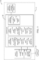
- Fig. 1 illustrates a non-limiting example of a data-fusion system 10, hereafter referred to as the system 10.
- the system 10 is that lidar-data and camera-data are fused or synergistically combined for use by an automated vehicle, e.g. a host-vehicle 12.
- an automated vehicle e.g. a host-vehicle 12.
- the term automated vehicle may apply to instances when the host-vehicle 12 is being operated in an automated-mode 14, i.e. a fully autonomous mode, where a human-operator of the host-vehicle 12 may do little more than designate a destination in order to operate the host-vehicle 12.
- full automation is not a requirement.
- the teachings presented herein are useful when the host-vehicle 12 is operated in a manual-mode 16 where the degree or level of automation may be little more than providing an audible or visual warning to the human-operator who is generally in control of the steering, accelerator, and brakes of the host-vehicle 12.
- the system 10 may merely assist the human-operator as needed to change lanes and/or avoid interference with and/or a collision with, for example, an object 20 such as an other-vehicle 22 ( Fig. 2 ), and/or to follow the other-vehicle 22 at some safe distance.
- the system 10 includes a camera 24 that renders an image 26 of the object 20 (e.g. the other-vehicle 22) proximate to, i.e. within two-hundred meters (200m) and typically within a line-of-sight of, the host-vehicle 12.
- the camera 24 may be a single imaging device that provides the image 26 from a single perspective, or the camera 24 may include multiple imaging devices mounted at different locations about the host-vehicle 12, where the output of the multiple imaging devices are combined to form the image 26, for example a three-hundred-sixty degree (360°) image.
- Various types of cameras suitable for use on the host-vehicle 12 are commercially available, as will be recognized by those in the art.
- the system 10 also includes a lidar 30 that detects a distance 32 and a direction 34 to the object 20.
- a lidar 30 that detects a distance 32 and a direction 34 to the object 20.
- various examples of the lidar 30 suitable for use on the host-vehicle 12 are commercially available.
- the camera 24 and the lidar 30 may be part of a unified assembly called an object-detector; however this is not a requirement. Co-locating the camera 24 and the lidar 30 may be advantageous to more easily align the respective fields-of-view of the camera 24 and the lidar 30, but various techniques to electrically align the outputs from these respective devices have been suggested.
- the system 10 also includes a controller 36 in communication with the camera 24 and the lidar 30.
- the controller 36 may include a processor (not specifically shown) such as a microprocessor or other control circuitry such as analog and/or digital control circuitry including an application specific integrated circuit (ASIC) for processing data as should be evident to those in the art.
- the controller 36 may include memory (not specifically shown), including nonvolatile memory, such as electrically erasable programmable read-only memory (EEPROM) for storing one or more routines, thresholds, and captured data.
- EEPROM electrically erasable programmable read-only memory
- the one or more routines may be executed by the processor to perform steps for determining when the object 20 is difficult for the lidar 30 to detect based on the image 26 received by the controller 36 from the camera 24.
- lidars sometimes have problems detecting an object that either strongly absorbs the infrared laser beams emitted by the lidar, or strongly reflects the infrared laser beams in directions other than towards the lidar.
- black painted surfaces tend to strongly absorb most of the light from the laser beams, at least more so than other colors.
- chrome-bumpers on vehicles tend to strongly reflect most of the light from the laser beams in directions other than towards the lidar, e.g. toward the sky or towards the ground.
- the reflected-signal i.e. the portion of the laser-beam emitted by the lidar that is reflected back toward the lidar, can be so weak that it is difficult for the lidar to detect the reflected-signal.
- Fig. 2 illustrates a non-limiting example of a scenario 40 where the other-vehicle 22 is located in front of or forward of the host-vehicle 12.
- the lidar 30 emits a plurality of laser-beams 42, and some of the laser-beams 42 may illuminate or impinge on the object 20 and be reflected by the object 20 back toward the lidar 30 to produce or provide one or more instances of a reflected-signal 44.
- the other-vehicle 22 may be equipped with a chrome-bumper 46 that acts like a mirror and reflects almost all of the laser-beam 42A and the laser-beam 42B in directions other than towards the lidar 30, so at least for the laser-beam 42A and the laser-beam 42B the object 20, or more specifically the chrome-bumper 46 goes undetected by the lidar 30.
- All or part of the other-vehicle 22 may be painted black or may have some other surface treatment that highly-absorbent to light, i.e. characterized as non-reflective.
- the laser-beam 42C may impinge or illuminate a spot on the other-vehicle 22 that is highly-absorbent to light or non-reflective.
- the system 10, or more specifically the controller 36 is configured or programmed to determine a reflectivity-characteristic 38 of the object 20, or the reflectivity-characteristic 38 of a portion of the object 20, based on the image 26 from the camera 24 and/or the reflected-signal 44 detected by the lidar 30.
- the reflectivity-characteristic 38 can be determined, some of which will now be described by way of non-limiting examples.
- the reflectivity-characteristic 38 of the object 20 can be determined or estimated is to compare a signal-strength 48 of the reflected-signal 44 to the size of the object 20 in the image 26.
- the reflected-signal 44 is illustrated as originating from a single instance of the laser-beams 42 only to simplify the illustration. Those in the art will recognize that there will likely be multiple instances of the reflected-signal 44 originating from many more than the three instances of the laser-beams 42 impinging on the object 20 as illustrated.
- the signal-strength 48 may be determined based on how many instances of the reflected-signal 44 are detected and comparing that value to an estimate of how many instances of the laser-beams 42 are expected or estimated to have impinged on the object 20 based on the size of the object 20 in the image 26. That is, if the object 20 is relatively large and/or close, it is expected that more instances of the laser-beams 42 will impinge on the object 20 than would be the case if the same object 20 was farther away, and/or the object 20 was relatively small.
- the signal-strength 48 of the reflected-signal 44 may be determined based on the intensity or brightness of the reflected-signal 44 as detected by the lidar 30. That the reflected-signal 44 may have been reflected by the object 20 may be determined by establishing a bounding-box around the object 20 in the image 26, and then relying on the aforementioned alignment between the camera 24 and the lidar 30 to determine which of the laser-beams 42 may have impinged on the object 20. That is, it can be determined if the reflected-signal 44 likely originated from within or outside of the bounding-box, and if from within the bounding-box it can be presumed that that the reflected-signal 44 was reflected by the object 20. From that intensity measurement the signal-strength 48 is determined, and from the signal-strength 48 and the distance 32 the reflectivity-characteristic of the object 20 or a portion of the object 20 can be determined.
- certain types or classifications of the reflectivity-characteristic 38 of the object 20 makes it difficult for the lidar 30 to detect the distance 32 and the direction 34 to the object 20.
- One way to characterize the object 20 or a surface of the object 20 that makes it difficult for the lidar 30 to detect the reflected-signal 44 is when a reflection-fraction 50 of light-energy (e.g. the laser-beams 42) from the lidar 30 that impinged on the object 20 and is reflected by the object 20 towards the lidar 30 is less than a fraction-threshold 52.
- a reflection-fraction 50 of light-energy e.g. the laser-beams 42
- the reflection-fraction 50 may be determined based on the signal-strength 48 of the reflected-signal 44 detected by the lidar 30. That is, if some value for the distance 32 is presumed so signal loss due to dispersion/divergence of the laser-beams 42 and the reflected-signal 44 can be considered, the signal-strength 48 (i.e. the intensity) of the reflected-signal 44 may be used to determine the reflection-fraction 50.
- the camera 24 may be configured or selected to be able to detect the infrared-light of the laser-beams 42, so the signal-strength of the reflected-signal 44 maybe determined from the image 26.
- the image 26 may be analyzed using image-processing to determine the ambient-light intensity about the object 20, and then examine the brightness of the object 20 in the image 26.
- the value of the fraction-threshold 52 may be determined by empirical testing. However it is contemplated that computer modeling may be useful to determine when the fraction-threshold 52 should be adjusted for various environmental conditions such during the precipitation of rain or snow, or the presence of fog.
- the reflection-fraction 50 may be less than the fraction-threshold 52 when a surface of the object 20 is characterized as non-reflective 54 such as when a color of the object 20 is black, i.e. painted black or covered with a black (e.g. flat-black) sticker, or other-wise treated so that a surface of the object 20 generally does not reflect light.
- the reflected-signal 44 shows the reflected-signal 44 as originating from the laser-beam 42C impinging on a painted surface of the other-vehicle 22. If this painted surface is black or flat-black, the reflected-signal 44 may be very weak because the reflection-fraction 50 may be less than the fraction-threshold 52.
- a reflection-fraction 50 seems to be less than a fraction-threshold 52 because the object 20 or a surface of the object 20 is characterized as highly-reflective 56, i.e. mirror-like. This would seem to be the polar-opposite of when the object is characterized as non-reflective 54.
- the reflections of those laser-beams may be almost entirely directed away from the lidar 30 as shown. So, even though the object 20 is characterized as highly-reflective 56, the reflection-fraction 50 may be less than the fraction-threshold 52 when a surface of the object 20 is chrome.
- a detection-characteristic 60 e.g. a detector-gain 62 and/or a detection-threshold 64
- Baseline calibration values of the detector-gain 62 and the detection-threshold 64 may be established through empirical testing to find a balance between noise rejection and sensitivity.
- the lidar 30 may not detect the reflected-signal 44 and/or may fail to determine that the reflected-signal 44 originated from the object 20.
- detector-gain 62 may be increased and/or the detection-threshold 64 may be decreased when the reflection-fraction 50 is less than the fraction-threshold 52. That is, because the presence of the object 20 is known from the image, the detection-characteristics 60 of the lidar 30 may be adjusted to better detect the distance 32 and/or the direction 34 to the object 20 even though there is a recognized increased risk of noise and or false detection. It is contemplated that the changes to the detection-characteristics 60 may be limited to a portion of the field-of-view of the lidar 30 that corresponds to or is aligned with the aforementioned bounding-box that is placed around the object 20 in the image 26.
- a data-fusion system (the system 10), a controller 36 for the system 10, and a method of operating the system 10 is provided.
- the system 10 provides a means for the detection-characteristics 60 of the lidar 30 to be dynamically adjusted to optimize the detection-characteristics 60 based on the reflectivity-characteristic of the object 20.
Landscapes
- Engineering & Computer Science (AREA)
- Physics & Mathematics (AREA)
- General Physics & Mathematics (AREA)
- Radar, Positioning & Navigation (AREA)
- Remote Sensing (AREA)
- Electromagnetism (AREA)
- Computer Networks & Wireless Communication (AREA)
- Aviation & Aerospace Engineering (AREA)
- Optics & Photonics (AREA)
- Automation & Control Theory (AREA)
- Multimedia (AREA)
- Signal Processing (AREA)
- Mechanical Engineering (AREA)
- Optical Radar Systems And Details Thereof (AREA)
- Traffic Control Systems (AREA)
- Length Measuring Devices By Optical Means (AREA)
Abstract
Description
- This disclosure generally relates to a data-fusion system that fuses lidar-data and camera-data, and more particularly relates to a system that determines a reflectivity-characteristic of an object based on an image from a camera, and adjust a detection-characteristic of a lidar when the reflectivity-characteristic of the object is such that a reflection-fraction of light-energy from the lidar that impinged on the object and is reflected by the object towards the lidar is less than a fraction-threshold.
- It is known Lidar has difficulty detecting black/non-reflective and chrome objects because a signal-strength of a reflected-signal is weak or non-existent.
- In accordance with one embodiment, a data-fusion system that fuses lidar-data and camera-data for an automated vehicle is provided. The system includes a camera, a lidar, and a controller. The camera renders an image of an object proximate to a host-vehicle. The lidar detects a distance and a direction to the object based on a reflected-signal of light reflected by the object. The controller is in communication with the camera and the lidar. The controller is configured to determine a reflectivity-characteristic of the object based on the image and the reflected-signal, and adjust a detection-characteristic of the lidar when the reflectivity-characteristic of the object makes it difficult for the lidar to detect the distance and the direction to the object.
- The reflectivity-characteristic of the object may be also determined based on a signal-strength of the reflected-signal. The reflectivity-characteristic of the object may make it difficult for the lidar to detect the distance and the direction to the object when a reflection-fraction of light-energy from the lidar that impinged on the object and is reflected by the object towards the lidar is less than a fraction-threshold. The reflection-fraction may be less than the fraction-threshold when a surface of the object is characterized as non-reflective. The reflection-fraction may be less than the fraction-threshold when a color of the object is black. The reflection-fraction may be less than the fraction-threshold when a surface of the object is characterized as highly-reflective. The reflection-fraction may be less than the fraction-threshold when a surface of the object is chrome. The detection-characteristic may include a detector-gain of the lidar, and the detector-gain may increase when the reflection-fraction is less than the fraction-threshold. The detection-characteristic may include a detection-threshold of the lidar, and the detection-threshold may decrease when the reflection-fraction is less than the fraction-threshold.
- Further features and advantages will appear more clearly on a reading of the following detailed description of the preferred embodiment, which is given by way of non-limiting example only and with reference to the accompanying drawings.
- The present invention will now be described, by way of example with reference to the accompanying drawings, in which:
-
Fig. 1 is a diagram of a data-fusion system in accordance with one embodiment; and -
Fig. 2 is a side-view of a scenario encountered by the system ofFig. 1 in accordance with one embodiment. -
Fig. 1 illustrates a non-limiting example of a data-fusion system 10, hereafter referred to as thesystem 10. As will be explained in more detail below, one aspect of thesystem 10 is that lidar-data and camera-data are fused or synergistically combined for use by an automated vehicle, e.g. a host-vehicle 12. As used herein, the term automated vehicle may apply to instances when the host-vehicle 12 is being operated in an automated-mode 14, i.e. a fully autonomous mode, where a human-operator of the host-vehicle 12 may do little more than designate a destination in order to operate the host-vehicle 12. However, full automation is not a requirement. It is contemplated that the teachings presented herein are useful when the host-vehicle 12 is operated in a manual-mode 16 where the degree or level of automation may be little more than providing an audible or visual warning to the human-operator who is generally in control of the steering, accelerator, and brakes of the host-vehicle 12. For example, thesystem 10 may merely assist the human-operator as needed to change lanes and/or avoid interference with and/or a collision with, for example, anobject 20 such as an other-vehicle 22 (Fig. 2 ), and/or to follow the other-vehicle 22 at some safe distance. - The
system 10 includes acamera 24 that renders animage 26 of the object 20 (e.g. the other-vehicle 22) proximate to, i.e. within two-hundred meters (200m) and typically within a line-of-sight of, the host-vehicle 12. Thecamera 24 may be a single imaging device that provides theimage 26 from a single perspective, or thecamera 24 may include multiple imaging devices mounted at different locations about the host-vehicle 12, where the output of the multiple imaging devices are combined to form theimage 26, for example a three-hundred-sixty degree (360°) image. Various types of cameras suitable for use on the host-vehicle 12 are commercially available, as will be recognized by those in the art. - The
system 10 also includes alidar 30 that detects adistance 32 and adirection 34 to theobject 20. Like thecamera 24, various examples of thelidar 30 suitable for use on the host-vehicle 12 are commercially available. As suggested inFig. 1 , thecamera 24 and thelidar 30 may be part of a unified assembly called an object-detector; however this is not a requirement. Co-locating thecamera 24 and thelidar 30 may be advantageous to more easily align the respective fields-of-view of thecamera 24 and thelidar 30, but various techniques to electrically align the outputs from these respective devices have been suggested. - The
system 10 also includes acontroller 36 in communication with thecamera 24 and thelidar 30. Thecontroller 36 may include a processor (not specifically shown) such as a microprocessor or other control circuitry such as analog and/or digital control circuitry including an application specific integrated circuit (ASIC) for processing data as should be evident to those in the art. Thecontroller 36 may include memory (not specifically shown), including nonvolatile memory, such as electrically erasable programmable read-only memory (EEPROM) for storing one or more routines, thresholds, and captured data. As will be explained in more detail below, the one or more routines may be executed by the processor to perform steps for determining when theobject 20 is difficult for thelidar 30 to detect based on theimage 26 received by thecontroller 36 from thecamera 24. - It has been observed that lidars sometimes have problems detecting an object that either strongly absorbs the infrared laser beams emitted by the lidar, or strongly reflects the infrared laser beams in directions other than towards the lidar. For example, black painted surfaces tend to strongly absorb most of the light from the laser beams, at least more so than other colors. As another example, chrome-bumpers on vehicles tend to strongly reflect most of the light from the laser beams in directions other than towards the lidar, e.g. toward the sky or towards the ground. In either case, the reflected-signal, i.e. the portion of the laser-beam emitted by the lidar that is reflected back toward the lidar, can be so weak that it is difficult for the lidar to detect the reflected-signal.
-
Fig. 2 illustrates a non-limiting example of ascenario 40 where the other-vehicle 22 is located in front of or forward of the host-vehicle 12. As will be recognized by those in the art, thelidar 30 emits a plurality of laser-beams 42, and some of the laser-beams 42 may illuminate or impinge on theobject 20 and be reflected by theobject 20 back toward thelidar 30 to produce or provide one or more instances of a reflected-signal 44. The other-vehicle 22 may be equipped with a chrome-bumper 46 that acts like a mirror and reflects almost all of the laser-beam 42A and the laser-beam 42B in directions other than towards thelidar 30, so at least for the laser-beam 42A and the laser-beam 42B theobject 20, or more specifically the chrome-bumper 46 goes undetected by thelidar 30. All or part of the other-vehicle 22 may be painted black or may have some other surface treatment that highly-absorbent to light, i.e. characterized as non-reflective. For example, the laser-beam 42C may impinge or illuminate a spot on the other-vehicle 22 that is highly-absorbent to light or non-reflective. - As a first step to overcome this problem, the
system 10, or more specifically thecontroller 36, is configured or programmed to determine a reflectivity-characteristic 38 of theobject 20, or the reflectivity-characteristic 38 of a portion of theobject 20, based on theimage 26 from thecamera 24 and/or the reflected-signal 44 detected by thelidar 30. There are numerous ways the reflectivity-characteristic 38 can be determined, some of which will now be described by way of non-limiting examples. - One way the reflectivity-
characteristic 38 of theobject 20 can be determined or estimated is to compare a signal-strength 48 of the reflected-signal 44 to the size of theobject 20 in theimage 26. InFig. 2 , the reflected-signal 44 is illustrated as originating from a single instance of the laser-beams 42 only to simplify the illustration. Those in the art will recognize that there will likely be multiple instances of the reflected-signal 44 originating from many more than the three instances of the laser-beams 42 impinging on theobject 20 as illustrated. The signal-strength 48 may be determined based on how many instances of the reflected-signal 44 are detected and comparing that value to an estimate of how many instances of the laser-beams 42 are expected or estimated to have impinged on theobject 20 based on the size of theobject 20 in theimage 26. That is, if theobject 20 is relatively large and/or close, it is expected that more instances of the laser-beams 42 will impinge on theobject 20 than would be the case if thesame object 20 was farther away, and/or theobject 20 was relatively small. - Alternatively, the signal-
strength 48 of the reflected-signal 44 may be determined based on the intensity or brightness of the reflected-signal 44 as detected by thelidar 30. That the reflected-signal 44 may have been reflected by theobject 20 may be determined by establishing a bounding-box around theobject 20 in theimage 26, and then relying on the aforementioned alignment between thecamera 24 and thelidar 30 to determine which of the laser-beams 42 may have impinged on theobject 20. That is, it can be determined if the reflected-signal 44 likely originated from within or outside of the bounding-box, and if from within the bounding-box it can be presumed that that the reflected-signal 44 was reflected by theobject 20. From that intensity measurement the signal-strength 48 is determined, and from the signal-strength 48 and thedistance 32 the reflectivity-characteristic of theobject 20 or a portion of theobject 20 can be determined. - As suggested above, certain types or classifications of the reflectivity-
characteristic 38 of theobject 20 makes it difficult for thelidar 30 to detect thedistance 32 and thedirection 34 to theobject 20. One way to characterize theobject 20 or a surface of theobject 20 that makes it difficult for thelidar 30 to detect the reflected-signal 44 is when a reflection-fraction 50 of light-energy (e.g. the laser-beams 42) from thelidar 30 that impinged on theobject 20 and is reflected by theobject 20 towards thelidar 30 is less than a fraction-threshold 52. - By way of example and not limitation, the reflection-
fraction 50 may be determined based on the signal-strength 48 of the reflected-signal 44 detected by thelidar 30. That is, if some value for thedistance 32 is presumed so signal loss due to dispersion/divergence of the laser-beams 42 and the reflected-signal 44 can be considered, the signal-strength 48 (i.e. the intensity) of the reflected-signal 44 may be used to determine the reflection-fraction 50. Alternatively, thecamera 24 may be configured or selected to be able to detect the infrared-light of the laser-beams 42, so the signal-strength of the reflected-signal 44 maybe determined from theimage 26. As another alternative, theimage 26 may be analyzed using image-processing to determine the ambient-light intensity about theobject 20, and then examine the brightness of theobject 20 in theimage 26. - The value of the fraction-
threshold 52 may be determined by empirical testing. However it is contemplated that computer modeling may be useful to determine when the fraction-threshold 52 should be adjusted for various environmental conditions such during the precipitation of rain or snow, or the presence of fog. As some further non-limiting example, the reflection-fraction 50 may be less than the fraction-threshold 52 when a surface of theobject 20 is characterized as non-reflective 54 such as when a color of theobject 20 is black, i.e. painted black or covered with a black (e.g. flat-black) sticker, or other-wise treated so that a surface of theobject 20 generally does not reflect light.Fig. 2 shows the reflected-signal 44 as originating from the laser-beam 42C impinging on a painted surface of the other-vehicle 22. If this painted surface is black or flat-black, the reflected-signal 44 may be very weak because the reflection-fraction 50 may be less than the fraction-threshold 52. - Another way to characterize the
object 20 or a surface of theobject 20 that makes it difficult for thelidar 30 to detect the reflected-signal 44 is when a reflection-fraction 50 seems to be less than a fraction-threshold 52 because theobject 20 or a surface of theobject 20 is characterized as highly-reflective 56, i.e. mirror-like. This would seem to be the polar-opposite of when the object is characterized as non-reflective 54. However, as suggested inFig. 2 , if the laser-beam 42A and the laser-beam 42B impinge on the chrome-bumper 46, the reflections of those laser-beams may be almost entirely directed away from thelidar 30 as shown. So, even though theobject 20 is characterized as highly-reflective 56, the reflection-fraction 50 may be less than the fraction-threshold 52 when a surface of theobject 20 is chrome. - Once the reflectivity-
characteristic 38 of theobject 20 is determined, it may be advantageous to adjust a detection-characteristic 60 (e.g. a detector-gain 62 and/or a detection-threshold 64) of thelidar 30 when the reflectivity-characteristic 38 of theobject 20 is such that a reflection-fraction 50 of light-energy from thelidar 30 that impinged on theobject 20 and is reflected by theobject 20 towards thelidar 30 is less than a fraction-threshold. Baseline calibration values of the detector-gain 62 and the detection-threshold 64 may be established through empirical testing to find a balance between noise rejection and sensitivity. That is, if the detector-gain 62 of thelidar 30 is too great, the ability of thelidar 30 to detect thedistance 32 and thedirection 34 to theobject 20 may be impaired because of excessive false detections. Similarly, if the detection-threshold 64 is set too low, similar problems with false detection may occur. In contrast, if detector-gain 62 is too low, and/or the detection-threshold 64 is too great, thelidar 30 may not detect the reflected-signal 44 and/or may fail to determine that the reflected-signal 44 originated from theobject 20. - However, given that the presence and approximate location of the
object 20 can be determined from theimage 26, detector-gain 62 may be increased and/or the detection-threshold 64 may be decreased when the reflection-fraction 50 is less than the fraction-threshold 52. That is, because the presence of theobject 20 is known from the image, the detection-characteristics 60 of thelidar 30 may be adjusted to better detect thedistance 32 and/or thedirection 34 to theobject 20 even though there is a recognized increased risk of noise and or false detection. It is contemplated that the changes to the detection-characteristics 60 may be limited to a portion of the field-of-view of thelidar 30 that corresponds to or is aligned with the aforementioned bounding-box that is placed around theobject 20 in theimage 26. - Accordingly, a data-fusion system (the system 10), a
controller 36 for thesystem 10, and a method of operating thesystem 10 is provided. Thesystem 10 provides a means for the detection-characteristics 60 of thelidar 30 to be dynamically adjusted to optimize the detection-characteristics 60 based on the reflectivity-characteristic of theobject 20. - While this invention has been described in terms of the preferred embodiments thereof, it is not intended to be so limited, but rather only to the extent set forth in the claims that follow.
Claims (9)
- A data-fusion system (10) that fuses lidar (30)-data and camera (24)-data for an automated vehicle, said system (10) comprising:a camera (24) that renders an image (26) of an object (20) proximate to a host-vehicle (12);a lidar (30) that detects a distance (32) and a direction (34) to the object (20) based on a reflected-signal (44) of light reflected by the object (20); anda controller (36) in communication with the camera (24) and the lidar (30), said controller (36) configured to determine a reflectivity-characteristic (38) of the object (20) based on the image (26) and the reflected-signal (44), and adjust a detection-characteristic (60) of the lidar (30) when the reflectivity-characteristic (38) of the object (20) makes it difficult for the lidar (30) to detect the distance (32) and the direction (34) to the object (20).
- The system (10) in accordance with claim 1, wherein the reflectivity-characteristic (38) of the object (20) is also determine based on a signal-strength (48) of the reflected-signal (44).
- The system (10) according to any one of the preceding claims, wherein the reflectivity-characteristic (38) of the object (20) makes it difficult for the lidar (30) to detect the distance (32) and the direction (34) to the object (20) when a reflection-fraction (50) of light-energy from the lidar (30) that impinged on the object (20) and is reflected by the object (20) towards the lidar (30) is less than a fraction-threshold (52).
- The system (10) in accordance with claim 3, wherein the reflection-fraction (50) is less than the fraction-threshold (52) when a surface of the object (20) is characterized as non-reflective (54).
- The system (10) in accordance with claim 3, wherein the reflection-fraction (50) is less than the fraction-threshold (52) when a color of the object (20) is black.
- The system (10) in accordance with claim 3, wherein the reflection-fraction (50) is less than the fraction-threshold (52) when a surface of the object (20) is characterized as highly-reflective (56).
- The system (10) in accordance with claim 3, wherein the reflection-fraction (50) is less than the fraction-threshold (52) when a surface of the object (20) is chrome.
- The system (10) according to any one of the claims 3 to 7, wherein the detection-characteristic (60) includes a detector-gain (62) of the lidar (30), and the detector-gain (62) is increased when the reflection-fraction (50) is less than the fraction-threshold (52).
- The system (10) according to any one of the claims 3 to 8, wherein the detection-characteristic (60) includes a detection-threshold (64) of the lidar (30), and the detection-threshold (64) is decreased when the reflection-fraction (50) is less than the fraction-threshold (52).
Applications Claiming Priority (1)
| Application Number | Priority Date | Filing Date | Title |
|---|---|---|---|
| US15/499,076 US10630913B2 (en) | 2017-04-27 | 2017-04-27 | Lidar and camera data fusion for automated vehicle |
Publications (2)
| Publication Number | Publication Date |
|---|---|
| EP3396408A1 true EP3396408A1 (en) | 2018-10-31 |
| EP3396408B1 EP3396408B1 (en) | 2021-09-22 |
Family
ID=61906659
Family Applications (1)
| Application Number | Title | Priority Date | Filing Date |
|---|---|---|---|
| EP18165670.3A Active EP3396408B1 (en) | 2017-04-27 | 2018-04-04 | Lidar and camera data fusion for automated vehicle |
Country Status (3)
| Country | Link |
|---|---|
| US (1) | US10630913B2 (en) |
| EP (1) | EP3396408B1 (en) |
| CN (1) | CN108802760B (en) |
Cited By (7)
| Publication number | Priority date | Publication date | Assignee | Title |
|---|---|---|---|---|
| CN115909272A (en) * | 2022-11-09 | 2023-04-04 | 杭州枕石智能科技有限公司 | Method for acquiring obstacle position information, terminal device and computer medium |
| US11861865B2 (en) | 2021-12-02 | 2024-01-02 | Argo AI, LLC | Automated vehicle pose validation |
| US12043290B2 (en) | 2022-06-08 | 2024-07-23 | Ford Global Technologies, Llc | State identification for road actors with uncertain measurements based on compliant priors |
| US12233918B2 (en) | 2022-01-21 | 2025-02-25 | Ford Global Technologies, Llc | Determining perceptual spatial relevancy of objects and road actors for automated driving |
| US12366462B2 (en) | 2022-01-14 | 2025-07-22 | Volkswagen Group of America Investments, LLC | Validating high definition mapping data |
| US12371010B2 (en) | 2021-12-28 | 2025-07-29 | Ford Global Technologies, Llc | Integrated trajectory forecasting, error estimation, and vehicle handling when detecting an observed scenario |
| DE102020121836B4 (en) * | 2019-08-22 | 2025-10-23 | Toyota Jidosha Kabushiki Kaisha | Object recognition device |
Families Citing this family (16)
| Publication number | Priority date | Publication date | Assignee | Title |
|---|---|---|---|---|
| US12123950B2 (en) | 2016-02-15 | 2024-10-22 | Red Creamery, LLC | Hybrid LADAR with co-planar scanning and imaging field-of-view |
| US11556000B1 (en) | 2019-08-22 | 2023-01-17 | Red Creamery Llc | Distally-actuated scanning mirror |
| US12399279B1 (en) | 2016-02-15 | 2025-08-26 | Red Creamery Llc | Enhanced hybrid LIDAR with high-speed scanning |
| US12399278B1 (en) | 2016-02-15 | 2025-08-26 | Red Creamery Llc | Hybrid LIDAR with optically enhanced scanned laser |
| US11953599B2 (en) * | 2017-01-26 | 2024-04-09 | Mobileye Vision Technologies Ltd. | Vehicle navigation based on aligned image and LIDAR information |
| CN108764187B (en) * | 2018-06-01 | 2022-03-08 | 百度在线网络技术(北京)有限公司 | Method, device, equipment, storage medium and acquisition entity for extracting lane line |
| US10708537B2 (en) * | 2018-07-28 | 2020-07-07 | Haas Laser Technologies, Inc. | System and method for reducing ghost images in a laser imaging system |
| US10627512B1 (en) * | 2018-11-29 | 2020-04-21 | Luminar Technologies, Inc. | Early fusion of lidar return data with camera information |
| CN109407115B (en) * | 2018-12-25 | 2022-12-27 | 中山大学 | Laser radar-based pavement extraction system and extraction method thereof |
| DE102020103794B4 (en) * | 2020-02-13 | 2021-10-21 | Daimler Ag | Method for calibrating a lidar sensor |
| CN111965625B (en) * | 2020-08-11 | 2023-02-21 | 上海禾赛科技有限公司 | Correction method and device for laser radar and environment sensing system |
| CN114114288B (en) * | 2020-08-27 | 2022-11-18 | 上海禾赛科技有限公司 | Measuring circuit for laser radar, measuring method thereof and laser radar |
| US12394085B2 (en) * | 2020-11-16 | 2025-08-19 | Waymo Llc | Long range distance estimation using reference objects |
| CN113688900A (en) * | 2021-08-23 | 2021-11-23 | 阿波罗智联(北京)科技有限公司 | Radar and visual data fusion processing method, road side equipment and intelligent traffic system |
| US20230176216A1 (en) * | 2021-12-03 | 2023-06-08 | Argo AI, LLC | Automatic bootstrap for autonomous vehicle localization |
| CN115129075B (en) * | 2022-06-28 | 2023-04-11 | 上海交通大学 | Three-dimensional imaging satellite formation control starting and controlling method based on time-space combination mechanism |
Citations (2)
| Publication number | Priority date | Publication date | Assignee | Title |
|---|---|---|---|---|
| US9261881B1 (en) * | 2013-08-01 | 2016-02-16 | Google Inc. | Filtering noisy/high-intensity regions in laser-based lane marker detection |
| US9383753B1 (en) * | 2012-09-26 | 2016-07-05 | Google Inc. | Wide-view LIDAR with areas of special attention |
Family Cites Families (3)
| Publication number | Priority date | Publication date | Assignee | Title |
|---|---|---|---|---|
| CN102944224B (en) * | 2012-11-09 | 2014-08-27 | 大连理工大学 | A working method of an automatic environment perception system for an unmanned vehicle |
| WO2016022359A1 (en) * | 2014-08-06 | 2016-02-11 | Cellomics, Inc. | Image-based laser autofocus system |
| EP3115742B1 (en) * | 2015-07-10 | 2020-04-15 | Hexagon Technology Center GmbH | 3d measuring machine |
-
2017
- 2017-04-27 US US15/499,076 patent/US10630913B2/en active Active
-
2018
- 2018-04-04 EP EP18165670.3A patent/EP3396408B1/en active Active
- 2018-04-27 CN CN201810391971.1A patent/CN108802760B/en active Active
Patent Citations (2)
| Publication number | Priority date | Publication date | Assignee | Title |
|---|---|---|---|---|
| US9383753B1 (en) * | 2012-09-26 | 2016-07-05 | Google Inc. | Wide-view LIDAR with areas of special attention |
| US9261881B1 (en) * | 2013-08-01 | 2016-02-16 | Google Inc. | Filtering noisy/high-intensity regions in laser-based lane marker detection |
Cited By (8)
| Publication number | Priority date | Publication date | Assignee | Title |
|---|---|---|---|---|
| DE102020121836B4 (en) * | 2019-08-22 | 2025-10-23 | Toyota Jidosha Kabushiki Kaisha | Object recognition device |
| US11861865B2 (en) | 2021-12-02 | 2024-01-02 | Argo AI, LLC | Automated vehicle pose validation |
| US12190541B2 (en) | 2021-12-02 | 2025-01-07 | Volkswagen Group of America Investments, LLC | Automated vehicle pose validation |
| US12371010B2 (en) | 2021-12-28 | 2025-07-29 | Ford Global Technologies, Llc | Integrated trajectory forecasting, error estimation, and vehicle handling when detecting an observed scenario |
| US12366462B2 (en) | 2022-01-14 | 2025-07-22 | Volkswagen Group of America Investments, LLC | Validating high definition mapping data |
| US12233918B2 (en) | 2022-01-21 | 2025-02-25 | Ford Global Technologies, Llc | Determining perceptual spatial relevancy of objects and road actors for automated driving |
| US12043290B2 (en) | 2022-06-08 | 2024-07-23 | Ford Global Technologies, Llc | State identification for road actors with uncertain measurements based on compliant priors |
| CN115909272A (en) * | 2022-11-09 | 2023-04-04 | 杭州枕石智能科技有限公司 | Method for acquiring obstacle position information, terminal device and computer medium |
Also Published As
| Publication number | Publication date |
|---|---|
| EP3396408B1 (en) | 2021-09-22 |
| US10630913B2 (en) | 2020-04-21 |
| CN108802760A (en) | 2018-11-13 |
| CN108802760B (en) | 2022-07-19 |
| US20180316873A1 (en) | 2018-11-01 |
Similar Documents
| Publication | Publication Date | Title |
|---|---|---|
| US10630913B2 (en) | Lidar and camera data fusion for automated vehicle | |
| US11961306B2 (en) | Object detection device | |
| US10591601B2 (en) | Camera-gated lidar system | |
| CN112639509B (en) | Radar power control method and device | |
| US10235875B2 (en) | Vehicle communication system for cloud-hosting sensor-data | |
| US10276049B2 (en) | Camera based trailer identification and blind zone adjustment | |
| US9506859B2 (en) | Method and device for determining a visual range in daytime fog | |
| CN104798084A (en) | Method and information system for filtering object information | |
| CN113348384A (en) | Adverse weather condition detection system with LIDAR sensor | |
| US20240125936A1 (en) | Time-resolved contrast imaging for lidar | |
| JP2023550508A (en) | Active sensor systems and object detection | |
| EP4066016B1 (en) | Fog detector for a vehicle with a specially shaped lens | |
| US20230366994A1 (en) | Method and device for determining false-positive detections of a lidar sensor | |
| US20240053438A1 (en) | Multipath Object Identification For Navigation | |
| US20240151813A1 (en) | Method for Checking a Functional Capability of a Distance Sensor of a Vehicle During Operation of the Vehicle, and Computing Device | |
| US20240012121A1 (en) | Method and device for detecting dirt on a viewing window of a lidar | |
| US12128916B2 (en) | Detection device and detection method | |
| US20190179013A1 (en) | Method for a lidar device for detecting a concealed object | |
| CN110308460B (en) | Parameter determination method and system of sensor | |
| EP2749899A2 (en) | Method for differentiating between a target object and an atmospheric component in a measurement with the aid of an optoelectronic sensor device of a motor vehicle, sensor device and motor vehicle | |
| JP4938838B2 (en) | Improved aircraft docking system | |
| US20190304123A1 (en) | Identification apparatus, identification method, and non-transitory recording medium storing identification program | |
| JP2021096120A (en) | Distance measuring device, distance measuring method, and distance measuring program | |
| US20240248176A1 (en) | Method and Device for Recognizing a Blockage of a Lidar System, and Vehicle | |
| US20220390229A1 (en) | Device and method for light-supported distance determination, control unit and working device |
Legal Events
| Date | Code | Title | Description |
|---|---|---|---|
| PUAI | Public reference made under article 153(3) epc to a published international application that has entered the european phase |
Free format text: ORIGINAL CODE: 0009012 |
|
| STAA | Information on the status of an ep patent application or granted ep patent |
Free format text: STATUS: THE APPLICATION HAS BEEN PUBLISHED |
|
| AK | Designated contracting states |
Kind code of ref document: A1 Designated state(s): AL AT BE BG CH CY CZ DE DK EE ES FI FR GB GR HR HU IE IS IT LI LT LU LV MC MK MT NL NO PL PT RO RS SE SI SK SM TR |
|
| AX | Request for extension of the european patent |
Extension state: BA ME |
|
| RAP1 | Party data changed (applicant data changed or rights of an application transferred) |
Owner name: APTIV TECHNOLOGIES LIMITED |
|
| STAA | Information on the status of an ep patent application or granted ep patent |
Free format text: STATUS: REQUEST FOR EXAMINATION WAS MADE |
|
| 17P | Request for examination filed |
Effective date: 20190429 |
|
| RBV | Designated contracting states (corrected) |
Designated state(s): AL AT BE BG CH CY CZ DE DK EE ES FI FR GB GR HR HU IE IS IT LI LT LU LV MC MK MT NL NO PL PT RO RS SE SI SK SM TR |
|
| RIN1 | Information on inventor provided before grant (corrected) |
Inventor name: WEI, JUNQING Inventor name: LEE, JONG HO Inventor name: KIM, JUNGSUNG |
|
| RAP1 | Party data changed (applicant data changed or rights of an application transferred) |
Owner name: MOTIONAL AD LLC |
|
| REG | Reference to a national code |
Ref country code: DE Ref legal event code: R079 Ref document number: 602018023807 Country of ref document: DE Free format text: PREVIOUS MAIN CLASS: G01S0017020000 Ipc: G01S0017420000 |
|
| RIC1 | Information provided on ipc code assigned before grant |
Ipc: G01S 17/931 20200101ALI20210308BHEP Ipc: G01S 17/86 20200101ALI20210308BHEP Ipc: G01S 17/42 20060101AFI20210308BHEP |
|
| GRAP | Despatch of communication of intention to grant a patent |
Free format text: ORIGINAL CODE: EPIDOSNIGR1 |
|
| STAA | Information on the status of an ep patent application or granted ep patent |
Free format text: STATUS: GRANT OF PATENT IS INTENDED |
|
| INTG | Intention to grant announced |
Effective date: 20210420 |
|
| GRAS | Grant fee paid |
Free format text: ORIGINAL CODE: EPIDOSNIGR3 |
|
| GRAA | (expected) grant |
Free format text: ORIGINAL CODE: 0009210 |
|
| STAA | Information on the status of an ep patent application or granted ep patent |
Free format text: STATUS: THE PATENT HAS BEEN GRANTED |
|
| AK | Designated contracting states |
Kind code of ref document: B1 Designated state(s): AL AT BE BG CH CY CZ DE DK EE ES FI FR GB GR HR HU IE IS IT LI LT LU LV MC MK MT NL NO PL PT RO RS SE SI SK SM TR |
|
| REG | Reference to a national code |
Ref country code: GB Ref legal event code: FG4D |
|
| REG | Reference to a national code |
Ref country code: IE Ref legal event code: FG4D |
|
| REG | Reference to a national code |
Ref country code: DE Ref legal event code: R096 Ref document number: 602018023807 Country of ref document: DE |
|
| REG | Reference to a national code |
Ref country code: CH Ref legal event code: EP Ref country code: AT Ref legal event code: REF Ref document number: 1432750 Country of ref document: AT Kind code of ref document: T Effective date: 20211015 |
|
| REG | Reference to a national code |
Ref country code: LT Ref legal event code: MG9D |
|
| REG | Reference to a national code |
Ref country code: NL Ref legal event code: MP Effective date: 20210922 |
|
| PG25 | Lapsed in a contracting state [announced via postgrant information from national office to epo] |
Ref country code: HR Free format text: LAPSE BECAUSE OF FAILURE TO SUBMIT A TRANSLATION OF THE DESCRIPTION OR TO PAY THE FEE WITHIN THE PRESCRIBED TIME-LIMIT Effective date: 20210922 Ref country code: FI Free format text: LAPSE BECAUSE OF FAILURE TO SUBMIT A TRANSLATION OF THE DESCRIPTION OR TO PAY THE FEE WITHIN THE PRESCRIBED TIME-LIMIT Effective date: 20210922 Ref country code: RS Free format text: LAPSE BECAUSE OF FAILURE TO SUBMIT A TRANSLATION OF THE DESCRIPTION OR TO PAY THE FEE WITHIN THE PRESCRIBED TIME-LIMIT Effective date: 20210922 Ref country code: SE Free format text: LAPSE BECAUSE OF FAILURE TO SUBMIT A TRANSLATION OF THE DESCRIPTION OR TO PAY THE FEE WITHIN THE PRESCRIBED TIME-LIMIT Effective date: 20210922 Ref country code: NO Free format text: LAPSE BECAUSE OF FAILURE TO SUBMIT A TRANSLATION OF THE DESCRIPTION OR TO PAY THE FEE WITHIN THE PRESCRIBED TIME-LIMIT Effective date: 20211222 Ref country code: BG Free format text: LAPSE BECAUSE OF FAILURE TO SUBMIT A TRANSLATION OF THE DESCRIPTION OR TO PAY THE FEE WITHIN THE PRESCRIBED TIME-LIMIT Effective date: 20211222 Ref country code: LT Free format text: LAPSE BECAUSE OF FAILURE TO SUBMIT A TRANSLATION OF THE DESCRIPTION OR TO PAY THE FEE WITHIN THE PRESCRIBED TIME-LIMIT Effective date: 20210922 |
|
| REG | Reference to a national code |
Ref country code: AT Ref legal event code: MK05 Ref document number: 1432750 Country of ref document: AT Kind code of ref document: T Effective date: 20210922 |
|
| PG25 | Lapsed in a contracting state [announced via postgrant information from national office to epo] |
Ref country code: LV Free format text: LAPSE BECAUSE OF FAILURE TO SUBMIT A TRANSLATION OF THE DESCRIPTION OR TO PAY THE FEE WITHIN THE PRESCRIBED TIME-LIMIT Effective date: 20210922 Ref country code: GR Free format text: LAPSE BECAUSE OF FAILURE TO SUBMIT A TRANSLATION OF THE DESCRIPTION OR TO PAY THE FEE WITHIN THE PRESCRIBED TIME-LIMIT Effective date: 20211223 |
|
| PG25 | Lapsed in a contracting state [announced via postgrant information from national office to epo] |
Ref country code: AT Free format text: LAPSE BECAUSE OF FAILURE TO SUBMIT A TRANSLATION OF THE DESCRIPTION OR TO PAY THE FEE WITHIN THE PRESCRIBED TIME-LIMIT Effective date: 20210922 |
|
| PG25 | Lapsed in a contracting state [announced via postgrant information from national office to epo] |
Ref country code: IS Free format text: LAPSE BECAUSE OF FAILURE TO SUBMIT A TRANSLATION OF THE DESCRIPTION OR TO PAY THE FEE WITHIN THE PRESCRIBED TIME-LIMIT Effective date: 20220122 Ref country code: SK Free format text: LAPSE BECAUSE OF FAILURE TO SUBMIT A TRANSLATION OF THE DESCRIPTION OR TO PAY THE FEE WITHIN THE PRESCRIBED TIME-LIMIT Effective date: 20210922 Ref country code: RO Free format text: LAPSE BECAUSE OF FAILURE TO SUBMIT A TRANSLATION OF THE DESCRIPTION OR TO PAY THE FEE WITHIN THE PRESCRIBED TIME-LIMIT Effective date: 20210922 Ref country code: PT Free format text: LAPSE BECAUSE OF FAILURE TO SUBMIT A TRANSLATION OF THE DESCRIPTION OR TO PAY THE FEE WITHIN THE PRESCRIBED TIME-LIMIT Effective date: 20220124 Ref country code: PL Free format text: LAPSE BECAUSE OF FAILURE TO SUBMIT A TRANSLATION OF THE DESCRIPTION OR TO PAY THE FEE WITHIN THE PRESCRIBED TIME-LIMIT Effective date: 20210922 Ref country code: NL Free format text: LAPSE BECAUSE OF FAILURE TO SUBMIT A TRANSLATION OF THE DESCRIPTION OR TO PAY THE FEE WITHIN THE PRESCRIBED TIME-LIMIT Effective date: 20210922 Ref country code: ES Free format text: LAPSE BECAUSE OF FAILURE TO SUBMIT A TRANSLATION OF THE DESCRIPTION OR TO PAY THE FEE WITHIN THE PRESCRIBED TIME-LIMIT Effective date: 20210922 Ref country code: EE Free format text: LAPSE BECAUSE OF FAILURE TO SUBMIT A TRANSLATION OF THE DESCRIPTION OR TO PAY THE FEE WITHIN THE PRESCRIBED TIME-LIMIT Effective date: 20210922 Ref country code: CZ Free format text: LAPSE BECAUSE OF FAILURE TO SUBMIT A TRANSLATION OF THE DESCRIPTION OR TO PAY THE FEE WITHIN THE PRESCRIBED TIME-LIMIT Effective date: 20210922 Ref country code: AL Free format text: LAPSE BECAUSE OF FAILURE TO SUBMIT A TRANSLATION OF THE DESCRIPTION OR TO PAY THE FEE WITHIN THE PRESCRIBED TIME-LIMIT Effective date: 20210922 |
|
| REG | Reference to a national code |
Ref country code: DE Ref legal event code: R097 Ref document number: 602018023807 Country of ref document: DE |
|
| PG25 | Lapsed in a contracting state [announced via postgrant information from national office to epo] |
Ref country code: DK Free format text: LAPSE BECAUSE OF FAILURE TO SUBMIT A TRANSLATION OF THE DESCRIPTION OR TO PAY THE FEE WITHIN THE PRESCRIBED TIME-LIMIT Effective date: 20210922 |
|
| PLBE | No opposition filed within time limit |
Free format text: ORIGINAL CODE: 0009261 |
|
| STAA | Information on the status of an ep patent application or granted ep patent |
Free format text: STATUS: NO OPPOSITION FILED WITHIN TIME LIMIT |
|
| 26N | No opposition filed |
Effective date: 20220623 |
|
| PG25 | Lapsed in a contracting state [announced via postgrant information from national office to epo] |
Ref country code: SI Free format text: LAPSE BECAUSE OF FAILURE TO SUBMIT A TRANSLATION OF THE DESCRIPTION OR TO PAY THE FEE WITHIN THE PRESCRIBED TIME-LIMIT Effective date: 20210922 |
|
| REG | Reference to a national code |
Ref country code: CH Ref legal event code: PL |
|
| REG | Reference to a national code |
Ref country code: BE Ref legal event code: MM Effective date: 20220430 |
|
| PG25 | Lapsed in a contracting state [announced via postgrant information from national office to epo] |
Ref country code: MC Free format text: LAPSE BECAUSE OF FAILURE TO SUBMIT A TRANSLATION OF THE DESCRIPTION OR TO PAY THE FEE WITHIN THE PRESCRIBED TIME-LIMIT Effective date: 20210922 Ref country code: LU Free format text: LAPSE BECAUSE OF NON-PAYMENT OF DUE FEES Effective date: 20220404 Ref country code: LI Free format text: LAPSE BECAUSE OF NON-PAYMENT OF DUE FEES Effective date: 20220430 Ref country code: IT Free format text: LAPSE BECAUSE OF FAILURE TO SUBMIT A TRANSLATION OF THE DESCRIPTION OR TO PAY THE FEE WITHIN THE PRESCRIBED TIME-LIMIT Effective date: 20210922 Ref country code: FR Free format text: LAPSE BECAUSE OF NON-PAYMENT OF DUE FEES Effective date: 20220430 Ref country code: CH Free format text: LAPSE BECAUSE OF NON-PAYMENT OF DUE FEES Effective date: 20220430 |
|
| PG25 | Lapsed in a contracting state [announced via postgrant information from national office to epo] |
Ref country code: BE Free format text: LAPSE BECAUSE OF NON-PAYMENT OF DUE FEES Effective date: 20220430 |
|
| PG25 | Lapsed in a contracting state [announced via postgrant information from national office to epo] |
Ref country code: IE Free format text: LAPSE BECAUSE OF NON-PAYMENT OF DUE FEES Effective date: 20220404 |
|
| P01 | Opt-out of the competence of the unified patent court (upc) registered |
Effective date: 20230525 |
|
| PG25 | Lapsed in a contracting state [announced via postgrant information from national office to epo] |
Ref country code: HU Free format text: LAPSE BECAUSE OF FAILURE TO SUBMIT A TRANSLATION OF THE DESCRIPTION OR TO PAY THE FEE WITHIN THE PRESCRIBED TIME-LIMIT; INVALID AB INITIO Effective date: 20180404 |
|
| PG25 | Lapsed in a contracting state [announced via postgrant information from national office to epo] |
Ref country code: SM Free format text: LAPSE BECAUSE OF FAILURE TO SUBMIT A TRANSLATION OF THE DESCRIPTION OR TO PAY THE FEE WITHIN THE PRESCRIBED TIME-LIMIT Effective date: 20210922 Ref country code: MK Free format text: LAPSE BECAUSE OF FAILURE TO SUBMIT A TRANSLATION OF THE DESCRIPTION OR TO PAY THE FEE WITHIN THE PRESCRIBED TIME-LIMIT Effective date: 20210922 Ref country code: CY Free format text: LAPSE BECAUSE OF FAILURE TO SUBMIT A TRANSLATION OF THE DESCRIPTION OR TO PAY THE FEE WITHIN THE PRESCRIBED TIME-LIMIT Effective date: 20210922 |
|
| PG25 | Lapsed in a contracting state [announced via postgrant information from national office to epo] |
Ref country code: MT Free format text: LAPSE BECAUSE OF FAILURE TO SUBMIT A TRANSLATION OF THE DESCRIPTION OR TO PAY THE FEE WITHIN THE PRESCRIBED TIME-LIMIT Effective date: 20210922 |
|
| PGFP | Annual fee paid to national office [announced via postgrant information from national office to epo] |
Ref country code: DE Payment date: 20250314 Year of fee payment: 8 |
|
| PG25 | Lapsed in a contracting state [announced via postgrant information from national office to epo] |
Ref country code: TR Free format text: LAPSE BECAUSE OF FAILURE TO SUBMIT A TRANSLATION OF THE DESCRIPTION OR TO PAY THE FEE WITHIN THE PRESCRIBED TIME-LIMIT Effective date: 20210922 |
|
| PGFP | Annual fee paid to national office [announced via postgrant information from national office to epo] |
Ref country code: GB Payment date: 20260323 Year of fee payment: 9 |