EP3396319A1 - Information processing system, information processing program, and information processing method - Google Patents
Information processing system, information processing program, and information processing method Download PDFInfo
- Publication number
- EP3396319A1 EP3396319A1 EP15911358.8A EP15911358A EP3396319A1 EP 3396319 A1 EP3396319 A1 EP 3396319A1 EP 15911358 A EP15911358 A EP 15911358A EP 3396319 A1 EP3396319 A1 EP 3396319A1
- Authority
- EP
- European Patent Office
- Prior art keywords
- motion
- gait
- change
- candidate
- section
- Prior art date
- Legal status (The legal status is an assumption and is not a legal conclusion. Google has not performed a legal analysis and makes no representation as to the accuracy of the status listed.)
- Granted
Links
Images










Classifications
-
- G—PHYSICS
- G01—MEASURING; TESTING
- G01C—MEASURING DISTANCES, LEVELS OR BEARINGS; SURVEYING; NAVIGATION; GYROSCOPIC INSTRUMENTS; PHOTOGRAMMETRY OR VIDEOGRAMMETRY
- G01C22/00—Measuring distance traversed on the ground by vehicles, persons, animals or other moving solid bodies, e.g. using odometers, using pedometers
- G01C22/006—Pedometers
-
- G—PHYSICS
- G01—MEASURING; TESTING
- G01C—MEASURING DISTANCES, LEVELS OR BEARINGS; SURVEYING; NAVIGATION; GYROSCOPIC INSTRUMENTS; PHOTOGRAMMETRY OR VIDEOGRAMMETRY
- G01C21/00—Navigation; Navigational instruments not provided for in groups G01C1/00 - G01C19/00
- G01C21/10—Navigation; Navigational instruments not provided for in groups G01C1/00 - G01C19/00 by using measurements of speed or acceleration
- G01C21/12—Navigation; Navigational instruments not provided for in groups G01C1/00 - G01C19/00 by using measurements of speed or acceleration executed aboard the object being navigated; Dead reckoning
- G01C21/16—Navigation; Navigational instruments not provided for in groups G01C1/00 - G01C19/00 by using measurements of speed or acceleration executed aboard the object being navigated; Dead reckoning by integrating acceleration or speed, i.e. inertial navigation
-
- A—HUMAN NECESSITIES
- A61—MEDICAL OR VETERINARY SCIENCE; HYGIENE
- A61B—DIAGNOSIS; SURGERY; IDENTIFICATION
- A61B5/00—Measuring for diagnostic purposes; Identification of persons
- A61B5/0002—Remote monitoring of patients using telemetry, e.g. transmission of vital signals via a communication network
- A61B5/0015—Remote monitoring of patients using telemetry, e.g. transmission of vital signals via a communication network characterised by features of the telemetry system
- A61B5/0022—Monitoring a patient using a global network, e.g. telephone networks, internet
-
- A—HUMAN NECESSITIES
- A61—MEDICAL OR VETERINARY SCIENCE; HYGIENE
- A61B—DIAGNOSIS; SURGERY; IDENTIFICATION
- A61B5/00—Measuring for diagnostic purposes; Identification of persons
- A61B5/103—Measuring devices for testing the shape, pattern, colour, size or movement of the body or parts thereof, for diagnostic purposes
- A61B5/107—Measuring physical dimensions, e.g. size of the entire body or parts thereof
- A61B5/1071—Measuring physical dimensions, e.g. size of the entire body or parts thereof measuring angles, e.g. using goniometers
-
- A—HUMAN NECESSITIES
- A61—MEDICAL OR VETERINARY SCIENCE; HYGIENE
- A61B—DIAGNOSIS; SURGERY; IDENTIFICATION
- A61B5/00—Measuring for diagnostic purposes; Identification of persons
- A61B5/103—Measuring devices for testing the shape, pattern, colour, size or movement of the body or parts thereof, for diagnostic purposes
- A61B5/11—Measuring movement of the entire body or parts thereof, e.g. head or hand tremor or mobility of a limb
- A61B5/112—Gait analysis
-
- A—HUMAN NECESSITIES
- A61—MEDICAL OR VETERINARY SCIENCE; HYGIENE
- A61B—DIAGNOSIS; SURGERY; IDENTIFICATION
- A61B5/00—Measuring for diagnostic purposes; Identification of persons
- A61B5/103—Measuring devices for testing the shape, pattern, colour, size or movement of the body or parts thereof, for diagnostic purposes
- A61B5/11—Measuring movement of the entire body or parts thereof, e.g. head or hand tremor or mobility of a limb
- A61B5/1123—Discriminating type of movement, e.g. walking or running
-
- A—HUMAN NECESSITIES
- A61—MEDICAL OR VETERINARY SCIENCE; HYGIENE
- A61B—DIAGNOSIS; SURGERY; IDENTIFICATION
- A61B5/00—Measuring for diagnostic purposes; Identification of persons
- A61B5/68—Arrangements of detecting, measuring or recording means, e.g. sensors, in relation to patient
- A61B5/6801—Arrangements of detecting, measuring or recording means, e.g. sensors, in relation to patient specially adapted to be attached to or worn on the body surface
- A61B5/6813—Specially adapted to be attached to a specific body part
- A61B5/6828—Leg
-
- A—HUMAN NECESSITIES
- A61—MEDICAL OR VETERINARY SCIENCE; HYGIENE
- A61B—DIAGNOSIS; SURGERY; IDENTIFICATION
- A61B5/00—Measuring for diagnostic purposes; Identification of persons
- A61B5/68—Arrangements of detecting, measuring or recording means, e.g. sensors, in relation to patient
- A61B5/6801—Arrangements of detecting, measuring or recording means, e.g. sensors, in relation to patient specially adapted to be attached to or worn on the body surface
- A61B5/683—Means for maintaining contact with the body
- A61B5/6831—Straps, bands or harnesses
-
- A—HUMAN NECESSITIES
- A61—MEDICAL OR VETERINARY SCIENCE; HYGIENE
- A61B—DIAGNOSIS; SURGERY; IDENTIFICATION
- A61B5/00—Measuring for diagnostic purposes; Identification of persons
- A61B5/72—Signal processing specially adapted for physiological signals or for diagnostic purposes
- A61B5/7235—Details of waveform analysis
- A61B5/7242—Details of waveform analysis using integration
-
- A—HUMAN NECESSITIES
- A61—MEDICAL OR VETERINARY SCIENCE; HYGIENE
- A61B—DIAGNOSIS; SURGERY; IDENTIFICATION
- A61B5/00—Measuring for diagnostic purposes; Identification of persons
- A61B5/72—Signal processing specially adapted for physiological signals or for diagnostic purposes
- A61B5/7235—Details of waveform analysis
- A61B5/725—Details of waveform analysis using specific filters therefor, e.g. Kalman or adaptive filters
-
- A—HUMAN NECESSITIES
- A61—MEDICAL OR VETERINARY SCIENCE; HYGIENE
- A61B—DIAGNOSIS; SURGERY; IDENTIFICATION
- A61B5/00—Measuring for diagnostic purposes; Identification of persons
- A61B5/72—Signal processing specially adapted for physiological signals or for diagnostic purposes
- A61B5/7235—Details of waveform analysis
- A61B5/7264—Classification of physiological signals or data, e.g. using neural networks, statistical classifiers, expert systems or fuzzy systems
-
- G—PHYSICS
- G16—INFORMATION AND COMMUNICATION TECHNOLOGY [ICT] SPECIALLY ADAPTED FOR SPECIFIC APPLICATION FIELDS
- G16H—HEALTHCARE INFORMATICS, i.e. INFORMATION AND COMMUNICATION TECHNOLOGY [ICT] SPECIALLY ADAPTED FOR THE HANDLING OR PROCESSING OF MEDICAL OR HEALTHCARE DATA
- G16H40/00—ICT specially adapted for the management or administration of healthcare resources or facilities; ICT specially adapted for the management or operation of medical equipment or devices
- G16H40/60—ICT specially adapted for the management or administration of healthcare resources or facilities; ICT specially adapted for the management or operation of medical equipment or devices for the operation of medical equipment or devices
- G16H40/67—ICT specially adapted for the management or administration of healthcare resources or facilities; ICT specially adapted for the management or operation of medical equipment or devices for the operation of medical equipment or devices for remote operation
-
- A—HUMAN NECESSITIES
- A61—MEDICAL OR VETERINARY SCIENCE; HYGIENE
- A61B—DIAGNOSIS; SURGERY; IDENTIFICATION
- A61B2562/00—Details of sensors; Constructional details of sensor housings or probes; Accessories for sensors
- A61B2562/02—Details of sensors specially adapted for in-vivo measurements
- A61B2562/0219—Inertial sensors, e.g. accelerometers, gyroscopes, tilt switches
-
- G—PHYSICS
- G16—INFORMATION AND COMMUNICATION TECHNOLOGY [ICT] SPECIALLY ADAPTED FOR SPECIFIC APPLICATION FIELDS
- G16H—HEALTHCARE INFORMATICS, i.e. INFORMATION AND COMMUNICATION TECHNOLOGY [ICT] SPECIALLY ADAPTED FOR THE HANDLING OR PROCESSING OF MEDICAL OR HEALTHCARE DATA
- G16H50/00—ICT specially adapted for medical diagnosis, medical simulation or medical data mining; ICT specially adapted for detecting, monitoring or modelling epidemics or pandemics
- G16H50/20—ICT specially adapted for medical diagnosis, medical simulation or medical data mining; ICT specially adapted for detecting, monitoring or modelling epidemics or pandemics for computer-aided diagnosis, e.g. based on medical expert systems
Definitions
- the present invention relates to an information processing system and the like.
- a technique of detecting gait initiation and gait termination by using sensor on both legs has conventionally been known. For example, there is a technique of detecting a sign of gait initiation based on angles of a back and a knee and then detecting toe-off based on a foot pressure on a shoe sole, thereby detecting gait initiation (for example, refer to Non Patent Document 1).
- a mobile terminal detects, when a walker holding the mobile terminal in his/her hand changes the direction of his/her steps, the direction change (for example, refer to Patent Document 1).
- a mobile terminal including an acceleration sensor and a GPS unit determines that a walker has changed the direction of his/her steps when the following conditions are met.
- the conditions specifically are that a first azimuth difference between a first traveling direction at a first time point and a third traveling direction at a third time point is equal to or larger than an angle threshold, and that a second azimuth difference between a second traveling direction at a second time point and a fourth traveling direction at a fourth time point is equal to or larger than the angle threshold.
- Non Patent Document 1 Automated detection of gait initiation and termination using wearable sensors Medical Engineering & Physics, Vol. 35, Issue 12, pp. 1713-1720 "
- the mobile terminal can detect a section of the direction change based on changes in the azimuth difference by using a sensor at a position at which the mobile terminal is held in a hand, but cannot detect a feature amount of individual direction change motions with high accuracy. This is because the sensor positioned at a position at which the terminal is held in a hand cannot detect individual step actions when a direction change is made with significantly small steps.
- it is an object to extract a feature amount of a direction change motion highly accurately only with sensors on both legs.
- An information processing system disclosed in the present application includes: a first motion sensor that is used for a left leg; a second motion sensor that is used for a right leg; and an information processing unit configured to process data acquired by the sensors.
- the information processing unit includes: a motion-candidate extracting unit configured to extract a point at which a motion of rotation of a leg about an axis in a direction of gravity occurs in the data acquired by the sensors, as a motion candidate of a direction change; a direction-change-motion determining unit configured to determine a plurality of motion candidates extracted by the motion-candidate extracting unit as a direction change motion when directions of the rotation are identical, and a motion candidate of the left leg and a motion candidate of the right leg alternately appear chronically successively; and a feature extracting unit configured to extract a feature of the direction change motion that is determined by the direction-change-motion determining unit, by using the data acquired by the sensors.
- a feature amount of a direction change motion can be extracted highly accurately only with sensors on both legs.
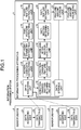
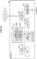
- FIG. 1 is a functional block diagram illustrating a configuration of an information processing system according to an embodiment.
- an information processing system 9 includes an information processing apparatus 1, and sensor devices 2, 3.
- the information processing apparatus 1 is connected to each of the sensor device 2 and the sensor device 3.
- the sensor device 2 is an angular velocity sensor (gyro sensor) around three axes that are perpendicular to each other, and is worn, for example, on a left leg of a subject. Axis directions of the sensor device 2 are explained referring to FIG. 2A .
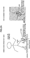
- FIG. 2A is a diagram for explaining directions of axes of a sensor device.
- "WHEN VIEWED FROM TOP” in FIG. 2A an angular velocity about a Z-axis is to be a displacement value along with rotation in a traverse (left-right) direction in walking of the subject. That is, it is a rotation amount in a left-right direction relative to a worn posture of the sensor device at a predetermine time point and, for example, a rotation amount in a rightward direction is plus (forward direction), and a rotation amount in a leftward direction is minus.
- an angular velocity about an X-axis is to be a displacement value along with rotation in a fore-and-aft direction in walking of the subject. That is, it is a rotation amount in a fore-and-aft direction relative to the worn posture of the sensor device 2 at a predetermined time point, and a rotation amount in a backward direction (lift-up direction) is plus (forward direction), and a rotation amount in a frontward direction (forward-leaning direction) is minus.
- An angular velocity about a Y-axis is to be a displacement value along with rotation in a body axis direction in walking of the subject.
- the sensor device 2 can be an acceleration sensor that detects acceleration in three axes perpendicular to each other.
- the sensor device 2 can include a gyro sensor and an acceleration sensor. In the following, explanation is given assuming that the sensor device 2 is a gyro sensor.
- the sensor device 2 includes a data acquiring unit 21 and a data transmitting unit 22.
- the data acquiring unit 21 acquires gyro data.
- the data transmitting unit 22 transmits the gyro data acquired by the data acquiring unit 21 to the information processing apparatus 1.
- the sensor device 3 is the same device as the sensor device 2, and is worn, for example, on a right leg of the subject. As the function thereof is the same as that of the sensor device 2, explanation thereof is omitted.
- FIG. 2B is a diagram illustrating one example of wearing of the sensor devices.
- the sensor devices 2, 3 are worn on both legs of a subject, respectively. Specifically, the sensor device 2 is worn on the left leg of the subject, and the sensor device 3 is worn on the right leg of the subject.
- the sensor devices 2, 3 communicate with the information processing apparatus 1, and transmit various kinds of data to the information processing apparatus 1 according to a direction change motion and a gait motion of the subject.
- the information processing apparatus 1 extracts feature amounts of the direction change motion and the gait motion of the subject by using only data from the sensor devices 2, 3 worn on the legs of the subject.
- the information processing apparatus 1 includes a data acquiring unit 11, a motion-candidate extracting unit 12, a left-right-symmetry extracting unit 13, a time-feature extracting unit 14, a phase-feature extracting unit 15, a direction-change-section determining unit 16, and a direction-change-feature extracting unit 17.
- the information processing apparatus 1 includes a before-and-after-section identifying unit 18, a gait-section determining unit 19, a gait-feature extracting unit 20, a feature-amount storage unit 21, a feature-amount visualizing unit 22, and a data storage unit 23.
- the sensor devices 2, 3 are one example of a first motion sensor and a second motion sensor, respectively.
- the information processing apparatus 1 is one example of an information processing unit.
- the data acquiring unit 11 receives various kinds of data that are transmitted respectively from the sensor devices 2, 3, and accumulates the received various kinds of data in the data storage unit 23. For example, the data acquiring unit 11 receives 60 samples each of the various kinds of data in one second, and accumulates the received various kinds of data.
- the various kinds of data include a rotation amount in a traverse (left-right) direction, a rotation amount in a fore-and-aft direction, and a rotation amount of a body axis.
- the various kinds of data are accumulated in the data storage unit 23 every each time point.
- the data acquiring unit 11 Having acquired a start instruction to extract a feature of a direction change, the data acquiring unit 11 reads various kinds of data of a corresponding subject from the data storage unit 23 based on the acquired instruction. The data acquiring unit 11 outputs the read various kinds of data to the motion-candidate extracting unit 12.
- the motion candidate extracting unit 12 extracts a portion at which a rotation amount in a traverse direction is larger than a first threshold, as a motion candidate. For example, the motion-candidate extracting unit 12 detects a peak from an angular velocity toward a traverse direction from among the various kinds of data that are output from the data acquiring unit 11. The peak detection is performed, applying a lowpass filter, such as a Butterworth filter, to the angler velocity data. The motion-candidate extracting unit 12 extracts a portion around this peak in one unit as a motion candidate of the direction change when the rotation amount toward the traverse direction around this peak is larger than the first threshold.
- a lowpass filter such as a Butterworth filter
- the motion-candidate extracting unit 12 can group these peaks and detect as one peak. This is because when a human takes a step, motion is complicated in rotation in the traverse direction compared to movement to a forward direction and peaks are likely to appear successively. Thus, the motion-candidate extracting unit 12 can extract one motion candidate of the direction change per step.
- the left-right-symmetry extracting unit 13 compares the motion candidate that is extracted by the motion-candidate extracting unit 12 with a next previous motion candidate, and extracts whether an actin candidate of the left leg and a motion candidate of the right leg appear alternately.
- the time-feature extracting unit 14 extracts a time interval between the motion candidate that is extracted by the motion-candidate extracting unit 12 and a next previous motion candidate.
- the phase-feature extracting unit 15 extracts whether rotation in the traverse direction of the motion candidate that is extracted by the motion-candidate extracting unit 12 is in the same direction (same phase) as a next previous motion candidate.
- the direction-change-section determining unit 16 determines a section in which the feature extracted by the time-feature extracting unit 14, the feature extracted by the left-right-symmetry extracting unit 13, and the feature extracted by the phase-feature extracting unit 15 satisfy a predetermined condition as a direction change section. Specifically, the direction-change-section determining unit 16 determines a section of a motion candidate in which the rotations in the traverse direction are in the same direction, and the left leg and the right leg rotate alternately, and that appears chronically successively, as the direction change motion, out of plural motion candidates extracted by the motion-candidate extracting unit 12.
- the direction-change-section determining unit 16 can determine the direction change section by probability by using the hidden Markov model (HMM) or the like. The method of determining the direction change section by using the hidden Markov model (HMM) is explained later.
- FIG. 3 is a diagram for explaining the direction-change section determination according to the embodiment. As expressed by solid lines in an upper diagram and a lower diagram in FIG. 3 , the angular velocity in the traverse direction of the left leg transmitted from the sensor device 2 and the angular velocity in the traverse direction of the right leg transmitted from the sensor device 3 are indicated chronologically in graphs. Doted lines in the graphs indicate the angular velocity in the forward direction.
- the motion-candidate extracting unit 12 applies a lowpass filter to a rotation amount in the traverse direction to detect a peak, and extracts, when a rotation amount in the traverse direction from a start of the peak until an end of the peak is larger than the first threshold, a portion around this peak in one unit as a motion candidate of the direction change.
- the rotation amount in the traverse direction of peaks p1 to p7 are larger than the first threshold. Therefore, the motion-candidate extracting unit 12 extracts the respective peaks p1 to p7 as motion candidates of the direction change.
- the time-feature extracting unit 14 extracts a time interval between the motion candidate that is extracted by the motion-candidate extracting unit 12 and a next previous motion candidate.
- a time interval between the peaks p1 and p2 being motion candidates is extracted as t1, as an example.
- a time interval between the peaks p2 and p3 being motion candidates is extracted.
- a time interval between the peaks p3 and p4 as motion candidates is extracted.
- a time interval between the peaks p4 and p5 being motion candidates is extracted.
- a time interval between the peaks p5 and p6 being motion candidates is extracted.
- the left-right-symmetry extracting unit 13 compares the motion candidate that is extracted by the motion-candidate extracting unit 12 with a next previous motion candidate, and extracts whether a motion candidate of the left leg and a motion candidate of the right leg appear alternately.
- the peak p2 is a motion candidate of the left leg and the next previous motion candidate
- the peak p1 is a motion candidate of the right leg
- alternate appearance is extracted.
- the peak p3 is a motion candidate of the right leg and the next previous motion candidate
- the peak p2 is the motion candidate of the left leg, alternate appearance is extracted.
- the peak p4 is a motion candidate of the left leg and the next previous motion candidate
- the peak p3 is the motion candidate of the right leg, alternate appearance is extracted.
- the peak p5 is a motion candidate of the right leg and the next previous motion candidate
- the peak p4 is the motion candidate of the left leg, alternate appearance is extracted.
- the peak p6 is a motion candidate of the left leg and the next previous motion candidate
- the peak p5 is the motion candidate of the right leg, alternate appearance is extracted.
- the peak p7 is a motion candidate of the left leg and the next previous motion candidate
- the peak p6 is the motion candidate of the right leg, alternate appearance is extracted.
- the phase-feature extracting unit 15 extracts whether rotation in the traverse direction of the motion candidate that is extracted by the motion-candidate extracting unit 12 is in the same direction (same phase) as that of the next previous motion candidate. In this example, as signs of the rotation amounts of the peaks p1 to p7 are all plus, it is extracted that all of them is in the same direction. Therefore, it is extracted that the peaks p1 to p7 are of the same direction (same phase).
- the direction-change-section determining unit 16 determines a section in which the feature extracted by the time-feature extracting unit 14, the feature extracted by the left-right-symmetry extracting unit 13, and the feature extracted by the phase-feature extracting unit 15 satisfy a predetermined condition as a direction change section. Specifically, the direction-change-section determining unit 16 determines a section of a motion candidate in which the rotations in the traverse direction are in the same direction, and the left leg and the right leg rotate alternately, and that appears chronically successively, as the direction change motion, out of plural motion candidates extracted by the motion-candidate extracting unit 12.
- the peaks p1 to p7 are motion candidates that appear chronically successively based on the feature extracted by the time-feature extracting unit 14. It is determined that the peaks p1 to p7 are motion candidates in which the left leg and the right leg rotate alternately (j2) based on the feature extracted by the left-right-symmetry extracting unit 13. It is determined that the peaks p1 to p7 are motion candidates of the same phase based on the feature extracted by the phase-feature extracting unit 15 (j3). Therefore, the section of the peaks p1 to p7 of the motion candidates is determined as the direction change section.
- FIG. 4 is a diagram illustrating one example of peak detection.
- FIG. 4 when a human takes a step, motion is often complicated in rotation in the traverse direction compared to movement to a forward direction. When the motion is complicated in rotation in the traverse direction, multiple peaks appear successively.
- An example of a case in which successive multiple peaks occur is when a leg rotates just before landing in a period from a pre-foot-off to a post-foot-strike. The pre-foot-off is before a foot is taken off. The post-foot-strike is after a foot strikes on.
- the motion candidate extracting unit 12 groups, when peaks of rotation in the same traverse direction successively appear in the same leg within predetermined time, these peaks.
- the predetermined time is 100 ms.
- the motion-candidate extracting unit 12 groups the peak p11 and the peak p12 as a peak p10.
- the motion-candidate extracting unit 12 can extract one motion candidate of the direction change of one step. Note that multiple peaks that appear successively in predetermine time is referred to as “multiplex peaks”, and grouping multiplex peaks is referred to as "chunking processing".
- the direction-change-feature extracting unit 17 extracts a feature of a direction change motion that has been determined by the direction-change-section determining unit 16, using data stored in the data storage unit 23. For example, the direction-change-feature extracting unit 17 extracts features relating to (A) how fast a direction change was done, (B) how large it was rotated, (C) whether it could rotate large from a start, (D) whether a direction change could be done stably, (E) whether a still state occurred during a direction change, and (F) how asymmetric between a left leg and a right leg. As an example of (A), ⁇ 1> a frequency of direction change motions during a direction change is extracted.
- ⁇ 2> a maximum duration of a direction change motion during a direction change is extracted.
- ⁇ 3> An average duration of a direction change motion during a direction change is extracted.
- B) ⁇ 4> a maximum rotation amount of a direction change motion during a direction change is extracted.
- ⁇ 5> An average rotation amount of a direction change motion during a direction change is extracted.
- C) ⁇ 6> a rotation amount of a first direction change motion during a direction change is extracted.
- D) ⁇ 7> an interval between adjacent direction change motions during a direction change is extracted.
- ⁇ 8> A lurch in a traverse direction right after foot strike is extracted.
- (E) As an example of (E), ⁇ 9> whether a still state is present, or a duration of a still state when a still state is present during a direction change is extracted.
- the features of a direction change motion that is extracted by the direction-change-feature extracting unit 17 are one example, and are not limited thereto.
- the before-and-after-section identifying unit 18 identifies a peak, the rotation amount in the traverse direction is equal to or smaller than a first threshold and equal to or larger than a second threshold out of peaks that occur right after (or right before) a direction change section that has been determined by the direction-change-section determining unit 16.
- the second threshold is a threshold smaller than the first threshold. That is, right after (or right before) a direction change motion is determined, a direction change can be made while walking. Therefore, the before-and-after-section identifying unit 18 identifies peaks when a direction change is made while walking. Such a direction change that occurs before and after a direction change is referred to as "mild direction change".
- a length of a section in which the identified mild direction change continues is extracted as a feature amount, and the before-and-after-section identifying unit 18 can thereby determine a difficulty of a direction change. Moreover, the before-and-after-section identifying unit 18 can determine a lurch after a direction change by extracting whether a direction of a mild direction change in the traverse direction is an opposite direction to a direction change right before that.
- the gait-section determining unit 19 identifies a gait section candidate between two direction change sections. For example, the gait-section determining unit 19 detects peaks from an angular velocity to a forward direction between two direction change sections, and identifies a peak, the rotation amount of which to the forward direction is equal to or larger than a threshold R1 out of the detected peaks. The gait-section determining unit 19 identifies a section in which the identified peaks successively occur in a short period of time as a gait section candidate. The gait-section determining unit 19 identifies a peak, the rotation amount to the forward direction of which is smaller than the threshold R1 and equal to or larger than the threshold R2 before and after the gait section candidate.
- the threshold R2 is a threshold smaller than the threshold R1.
- Such a section of peaks identified before and after a gait section candidate is referred to as "transition gait section”.
- the "transition gait section” is a section of unstable walking until the walking is stabilized.
- the gait-section determining unit 19 determines the first peak in a transition gait section as the "first step”, and determines the last peak as the "last step”.
- a section including the transition gait section and the gait section candidate is referred to as "gait section" for convenience.
- the method of determining the "gait section” is not limited thereto.
- the gait-section determining unit 19 can determine the gait section by using the hidden Markov model (HMM).
- HMM hidden Markov model
- the method of determining the "gait section” by using the hidden Markov model (HMM) is described later.
- the transition gait section is an unstable section in terms of walking and a section of the mild direction change is an unstable section in terms of direction change, these sections can be determined in a duplicated manner.
- the method of determining the transition gait section is not limited thereto.
- the gait-section determining unit 19 can determine a section from the first step until first several steps (for example, four steps) are completed as the transition gait section, out of a section that has been determined as the gait section.
- first several steps for example, four steps
- a method of determining the transition gait section by using a distribution of time intervals of peaks is described later.
- the gait-feature extracting unit 20 extracts a feature of the transition gait section that has been identified by the gait-section determining unit 19 by using data stored in the data storage unit 23. For example, the gait-feature extracting unit 20 extracts features relating to (a) how fast it turned into stable walking, and (b) with how few lurch, it turned into stable walking. As an example of (a), time and the number of steps until it turned into stable walking are extracted. As an example of (b), a rotation amount in a traverse direction until it turned into stable walking is extracted.
- the feature-amount storage unit 21 stores feature amounts in the direction change section and the transition gait section chronologically in the data storage unit 23.
- the feature-amount storage unit 21 stores various kinds of feature amount of the direction change section extracted by the direction-change-feature extracting unit 17 and various kinds of feature amount of the transition gait section extracted by the gait-feature extracting unit 20 in order of occurrence in the data storage unit 23.
- the feature-amount visualizing unit 22 visualizes various kinds of feature amount stored in the data storage unit 23 in chronological order. For example, when the subject is a patient, the feature-amount visualizing unit 22 visualizes statistical values of various kinds of feature amount per month for sections before and after relative to the day on which the patient is treated, to monitor the treatment progress.
- An example of the feature amount includes the number of times of direction change motion during a direction change.
- FIG. 5 is a diagram for explaining the gait section determination according to the embodiment. As illustrated in upper and lower diagrams in FIG. 5 , the angular velocity in the forward direction of the left leg transmitted from the sensor device 2 and the angular velocity in the forward direction of the right leg transmitted from the sensor device 3 are indicated chronologically in graphs per time.
- the gait-section determining unit 19 applies a lowpass filter to the rotation amount in the forward direction between two direction change sections to detect peaks, and identifies a peak, the rotation amount in the forward direction of which is equal to or larger than the threshold R1.
- respective rotation amounts of peaks p21 to p27 are equal to or larger than the threshold R1. Therefore, the gait-section determining unit 19 identifies a section in which the peaks p21 to p27 successively occur in a short period of time as a gait section candidate.
- the gait-section determining unit 19 identifies peaks before and after the gait section candidate, and identifies a peak, the rotation amount in the forward direction of which is smaller than the threshold R1 and equal to or larger than the threshold R2 out of the identified peaks.
- rotation amounts of peak p20 and p30 in the forward direction are smaller than the threshold R1 and equal to or larger than the threshold R2. Therefore, the gait-section determining unit 19 determines that the peak p20 before the gait section candidate as the first one step.
- the gait-section determining unit 19 determines the peak p30 after the gait section candidate as the last one step.
- FIG. 6 is a flowchart of entire information processing according to the embodiment. It is assumed that the data acquiring unit 11 has accepted a start instruction to extract a feature of a direction change for a specific subject. It is assumed that gyro sensor data from the sensor devices 2, 3 that are worn by the specific subject is stored in the data storage unit 23.
- the data acquiring unit 11 acquires gyro sensor data corresponding to the specific subject from the data storage unit 23 (step S11).
- the direction-change-section determining unit 16 extracts a direction change section (step S12). A detailed flowchart is described later.
- the direction-change-feature extracting unit 17 extracts a feature amount of the direction change (step S13). A detailed flowchart is described later.
- the before-and-after-section identifying unit 18 identifies sections before and after the direction change section (step S14). For example, the before-and-after-section identifying unit 18 identifies a peak, the rotation amount in the traverse direction of which is equal to or smaller than the first threshold and equal to or larger than the second threshold out of peaks that occur right after the direction change section. That is, the before-and-after-section identifying unit 18 identifies a section of a mild change of direction (mild direction change) that occurs before and after the direction change section.
- the gait-section determining unit 19 extracts a transition gait section (step S15). A detailed flowchart is described later.
- the gait-feature extracting unit 20 extracts a feature amount of transition gait from the transition gait section (step S16). A detailed flow chart is described later.
- the feature-amount storage unit 21 stores feature amounts of a direction change and a transition gait in a DB (database) (step S17).
- the feature-amount storage unit 21 stores various kinds of feature amount of the direction change section extracted by the direction-change-feature extracting unit 17 and various kinds of feature amount of the transition gait section extracted by the gait-feature extracting unit 20 in order of occurrence in the data storage unit 23.
- the feature-amount visualizing unit 22 visualizes a feature amount (step S18). For example, the feature-amount visualizing unit 22 visualizes various kinds of feature amount stored in the data storage unit 21 in chronological order.
- FIG. 7A to FIG. 7C are flowcharts of the direction-change-section extraction processing according to the embodiment.
- the motion-candidate extracting unit 12 extracts a motion candidate point from traverse direction gyro data of the left leg (step S21). For example, the motion-candidate extracting unit 12 detects a peak from the rotation amount in the traverse direction of the left leg out of data stored in the data storage unit 23.
- the motion-candidate extracting unit 12 extracts a motion candidate point from traverse direction gyro data of the right leg (step S22). For example, the motion-candidate extracting unit 12 detects a peak from the rotation amount in the traverse direction of the right leg out of data stored in the data storage unit 23.
- the motion-candidate extracting unit 12 performs chunking processing of multiplex peaks (step S23). That is, the motion-candidate extracting unit 12 groups, when peaks of rotation in the same traverse direction appear successively in the same leg within predetermined time (for example, 100 ms), the peaks into one unit of peak.
- the motion-candidate extracting unit 12 sets an initial value 1 to an index i (step S24).
- the motion-candidate extracting unit 12 calculates a rotation amount in the traverse direction at an i-th motion candidate point (step S25).
- the motion-candidate extracting unit 12 excludes the calculated rotation amount in the traverse direction when it is equal to or smaller than a threshold (step S26).
- the threshold herein is, for example, the first threshold described above.
- the motion-candidate extracting unit 12 determines whether the index i is smaller than a total number N of motion candidate points (step S27). When the index i is smaller than the total number N of motion candidate points (step S27: YES), the motion-candidate extracting unit 12 adds 1 to the index i (step S28), and shifts to step S25 to process the next index i.
- the direction-change-section determining unit 16 sets the initial value 1 to the index i (step S29).
- the direction-change-section determining unit 16 acquires time information and information of a belonging leg at i-th and i+1-th motion candidate points (step S30).
- the left-right-symmetry extracting unit 13 extracts left-right symmetry of two motion candidate points (step S31). That is, the left-right-symmetry extracting unit 13 extracts a feature indicating whether the left leg and the right leg alternately appear, for successive two motion candidate points by using information indicating which side of leg to which a motion candidate point belongs (hereinafter, refer to as leg side).
- the time-feature extracting unit 14 extracts a time feature of the two motion candidate points (step S32). That is, the time-feature extracting unit 14 extracts a time interval of successive the two motion candidate points by using time information.
- the phase-feature extracting unit 15 extracts a phase feature of the two motion candidate points (step S33). That is, the phase-feature extracting unit 15 extracts a phase feature indicating whether rotations in the traverse direction are the same direction, for the successive two motion candidate points.
- the direction-change-section determining unit 16 determines whether the index i is smaller than a total number M of motion candidates (step S34). When the index i is smaller than the total number M of motion candidate points (step S34: YES), the direction-change-section determining unit 16 adds 1 to the index i (step S35), and shifts to step S30 to process the next index i.
- step S34 when the index i is equal to or larger than the total number M of motion candidate points (step S34: NO), the direction-change-section determining unit 16 acquires determination parameters (step S36).
- the direction-change-section determining unit 16 determines a section in which motion candidate points of the left leg and the right leg occur "alternately”, “successively”, and “in the same phase” as a direction change section, by using the determination parameters (step S37).
- the direction-change-section determining unit 16 ends the direction-change-section extraction processing.
- FIG. 8 is a flowchart of direction-change feature-amount-extraction processing according to the embodiment.
- the direction-change-feature extracting unit 17 sets the initial value 1 to an index j (step S41). j is the index indicating a direction change section. The direction-change-feature extracting unit 17 sets the initial value 1 to the index i (step S42). i is the index indicating a motion candidate point.
- the direction-change-feature extracting unit 17 acquires time information of a i-th subject motion point in a j-th direction change section from various kinds of data stored in the data storage unit 23 (step S43).
- the rotation amount of the subject motion point can be acquired by calculating an integrated value of gyro in the traverse direction from a start time until an end time at the subject motion point, as one example.
- the direction-change-feature extracting unit 17 (b) extracts a rotational speed at the subject motion point (step S45).
- the rotational speed of the subject motion point can be acquired by extracting a maximum value of gyro in the traverse direction from the start time until the end time at the subject motion point.
- the direction-change-feature extracting unit 17 (c) extracts a rotation duration of the subject motion point (step S46).
- the rotation duration of the subject motion point can be acquired by calculating a section width from the start time until the end time of the subject motion point.
- the direction-change-feature extracting unit 17 (d) extracts an advancement amount of the subject motion point (step S47).
- the advancement amount of the subject motion point can be acquired by extracting an integrated value of gyro in the fore-and-aft direction from the start time until the end time of the subject motion point.
- the direction-change-feature extracting unit 17 determines whether the index i is smaller than the total number M of motion candidate points (step S48). When the index i is smaller than the total number M of the motion candidate point (step S48: YES), the direction-change-feature extracting unit 17 adds 1 to the index i (step S49), and shifts to step S43 to process the next index i.
- the direction-change-feature extracting unit 17 calculates a statistic of the direction change section j as follows.
- the direction-change-feature extracting unit 17 calculates an average value, a maximum value, a minimum value, a distribution, and a left-right ratio of the respective feature amounts (a) to (d) (step S50).
- the direction-change-feature extracting unit 17 extracts the feature amounts (a) to (d) of a direction-change start motion and a direction-change end motion (step S51).
- the direction-change start motion is a motion at the first motion candidate point.
- the direction-change end motion is a motion at the M-th motion candidate point.
- the direction-change-feature extracting unit 17 calculates a total number of motion points, a duration, a total rotation amount, a total advancement amount, a rotation amount/advancement amount ratio, and whether a still state section is present (step S52) .
- the direction-change-feature extracting unit 17 determines whether the index j is smaller than a total number L of the direction change section (step S53). When the index j is smaller than the total number L of the direction change section (step S53: YES), the direction-change-feature extracting unit 17 adds 1 to the index j (step S54), and shifts to step S42 to process the next index j.
- step S53 NO
- the direction-change-feature extracting unit 17 ends the direction-change-feature extraction processing.
- FIG. 9A to FIG. 9C are flowcharts of the transition-gait-section extraction processing according to the embodiment.
- the gait-section determining unit 19 extracts a motion candidate point from fore-and-aft direction gyro data of the left leg (step S61). For example, the gait-section determining unit 19 detects a peak from the rotation amount in the fore-and-aft direction of the left leg out of data stored in the data storage unit 23.
- the gait-section determining unit 19 extracts a motion candidate point from fore-and-aft direction gyro data of the right leg (step S62). For example, the gait-section determining unit 19 detects a peak from the rotation amount in the forward direction of the right leg out of data stored in the data storage unit 23.
- the gait-section determining unit 19 sets the initial value 1 to an index p (step S63).
- the gait-section determining unit 19 calculates a rotation amount (gait speed amount) in the fore-and-aft direction of a p-th motion candidate point (step S64).
- the gait-section determining unit 19 excludes from the motion candidate point if the gait speed amount is equal to or smaller than a threshold (step S65).
- the threshold herein is, for example, the threshold R2 described above.
- the gait-section determining unit 19 determines whether an index p is smaller than a total number P of motion candidate points (step S66). When the index p is smaller than the total number P of the motion candidate point (step S66: YES), the gait-section determining unit 19 adds 1 to the index p (step S67), and shifts to step S64 to process the next index p.
- the gait-section determining unit 19 sets the initial value 1 to an index q (step S68).
- the gait-section determining unit 19 acquires time information and information of a belonging leg at q-th and q+1-th motion candidate points (step S69).
- the gait-section determining unit 19 extracts left-right symmetry of two motion candidate points (step S70). That is, the gait-section determining unit 19 extracts a feature indicating whether the left leg and the right leg alternately appear, for successive two motion candidate points by using information of a belonging leg to which a motion candidate point belongs.
- the gait-section determining unit 19 extracts a time feature of the two motion candidate points (step S71). That is, the gait-section determining unit 19 extracts a time interval of the successive two motion candidate points by using time information.
- the gait-section determining unit 19 determines whether the index q is smaller than a total number Q of motion candidates (step S72). When the index q is smaller than the total number Q of motion candidate points (step S72: YES), the gait-section determining unit 19 adds 1 to the index q (step S73), and shifts to step S69 to process the next index q.
- step S74 when the index q is equal to or larger than the total number Q of motion candidate points (step S72: NO), the gait-section determining unit 19 acquires determination parameters (step S74).
- the gait-section determining unit 19 determines a section in which motion candidate points of the left leg and the right leg occur "alternately" and “successively" as a gait section, by using the determination parameters (step S75).
- the gait-section determining unit 19 regards motion candidate points in the determined gait section as motion points.
- the gait-section determining unit 19 then extracts a time interval between motion points in the determined gait section (step S76).
- the gait-section determining unit 19 sets the initial value 1 to the index i step (S77).
- the gait-section determining unit 19 acquires a time interval between adjacent motion points among the i-th to the (i+n-1)-th motion points (step S78).
- n herein is the number of motion points that are used to determine whether it is a transition gait. n is, for example, 4, but not limited thereto.
- the gait-section determining unit 19 calculates a distribution of time intervals of n pieces of motion points (step S79). The gait-section determining unit 19 determines whether the distribution is smaller than a threshold (step S80). When the distribution is equal to or larger than the threshold (step S80: NO), the gait-section determining unit 19 adds 1 to the index i (step S81), and calculates a next distribution. This is because the distribution is not converged.
- the gait-section determining unit 19 identifies a section from a time when the first gait step starts until a time when the (i-1)-th gait step is finished, as a transition gait section (step S82). This is because the distribution has been converged.
- the gait-section determining unit 19 ends gait-section-identification processing.
- FIG. 10 is a flowchart of transition-gait-feature extraction processing according to the embodiment.
- the gait-feature extracting unit 20 sets the initial value 1 to index r (step S91). r is the index indicating a gait section.
- the gait-feature extracting unit 20 sets the initial value 1 to index q (step S92). q is the index indicating a motion point.
- the gait-feature extracting unit 20 acquires time information of a q-th subject motion point in an r-th transition gait section from various kinds of data stored in the data storage unit 23 (step S93).
- the gait-feature extracting unit 20 (v) extracts a step length of a subject motion point (step S94).
- the step length of the subject motion point can be acquired by calculating an integrated value of gyro in the fore-and-aft direction from a start time until an end time of the subject motion point, and by multiplying the integrated value by a predetermined coefficient.
- the gait-feature extracting unit 20 (w) extracts a gait speed at the subject motion point (step S95).
- the gait speed of the subject motion point can be acquired by extracting a maximum value of gyro in the fore-and-aft direction from the start time until the end time of the subject motion point.
- the gait-feature extracting unit 20 (x) extracts a duration of a swing phase of the subject motion point (step S96).
- the duration of the swing phase of the subject motion point can be acquired by calculating a section width from the start time until the end time of the subject motion point.
- the gait-feature extracting unit 20 (y) extracts a foot lift amount of the subject motion point (step S97).
- the foot lift amount of the subject motion point can be acquired by calculating an integrated value of gyro in the vertical direction from the start time until the end time of the subject motion point.
- the gait-feature extracting unit 20 (z) extracts a left-right movement amount of the subject motion point (step S98).
- the left-right movement amount of the subject motion point can be acquired by calculating an integrated value of gyro in a left-and-right direction from the start time until the end time of the subject motion point.
- the gait-feature extracting unit 20 determines whether the index q is smaller than the total number Q of motion candidate points (step S99). When the index q is smaller than the total number Q of motion candidate points (step S99: YES), the gait-feature extracting unit 20 adds 1 to the index q (step S100), and shifts to step S93 to process the next index q.
- the gait-feature extracting unit 20 calculates a statistic of the gait section r as follows.
- the gait-feature extracting unit 20 calculates an average value, a maximum value, a minimum value, a distribution, and a left-right ratio of the respective feature amounts (v) to (z) (step S101).
- the gait-feature extracting unit 20 extracts the feature amounts (v) to (z) of the first step and the second step (step S102).
- the gait-feature extracting unit 20 extracts a time interval in a section between an end of the direction change and a start of the transition gait, and a foot movement amount of each leg (step S103).
- the gait-feature extracting unit 20 determines whether the index r is smaller than the total number R of the gai sections (step S104). When the index r is smaller than the total number R of the gait sections (step S104: YES), the gait-feature extracting unit 20 adds 1 to the index r (step S105), and shifts to step S92 to process the next index r.
- step S104 when the index r is equal to or larger than the total number R of the gait sections (step S104: NO), the gait-feature extracting unit 20 ends the gait-feature extraction processing.
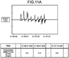
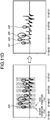
- FIG. 11A to FIG. 11E illustrate a specific example of the motion-candidate extraction processing according to the embodiment.
- the motion-candidate extracting unit 12 extracts a gyro in the traverse direction of the right leg (angular velocity in the traverse direction) per time from the data storage unit 23.
- a value of gyro in the traverse direction at "21:06:51.800” is "0.0 (deg/s).
- a value of gyro in the traverse direction at "21:06:51.820” is "0.3" (deg/s).
- a value of gyro in the traverse direction at "21:07:14.400” is "0.8" (deg/s).
- the motion-candidate extracting unit 12 detects a peak from a rotation amount in the traverse direction.
- a peak of a peak number "1" is detected at "21:06:55.640” as the occurrence time.
- a peak of a peak number "2" is detected at "21:06:56.840" as the occurrence time.
- the motion-candidate extracting unit 12 performs chunking processing when multiplex peaks are detected. That is, the motion-candidate extracting unit 12 groups, when peaks of rotation in the same traverse direction successively appear in the same leg within predetermined time, these peaks. In this example, a peak of a peak number "3" and a peak of a peak number "4" appear successively in predetermined time. Therefore, the motion-candidate extracting unit 12 groups the peak of the peak number "3" and the peak of the peak number "4" into one unit of peak of the peak number "3".
- the motion-candidate extracting unit 12 identifies a start position and an end position of each peak.
- the motion-candidate extracting unit 12 refers a gyro before the peak and identifies a time at which a gyro change lowers a threshold in a small time width as the start position.
- the motion-candidate extracting unit 12 refers a gyro after the peak and identifies a time at which a gyro change lowers a threshold in a small time width as the end position.
- a time Ts at which a gyro change lowers a threshold in a small time width is identified as the start position.
- a time Te at which a gyro change lowers a threshold in a small time width is identified as the end position.
- the motion-candidate extracting unit 12 calculates a gyro integrated value in the traverse direction from the start position to the end position as a rotation amount in the traverse direction for each peak.
- the rotation amount in the traverse direction is calculated by following Equation (1).
- i is the peak number.
- Ts(i) is the peak start position of i-th motion candidate point.
- Te(i) is the peak end position of the i-th motion candidate point.
- r(i) is a rotation amount in the traverse direction of the i-th motion candidate point.
- r i ⁇ t ⁇ Ts i , Te i gyroY t
- the motion-candidate extracting unit 12 determines whether a rotation amount in the traverse direction is larger than the first threshold for each peak.
- the motion-candidate extracting unit 12 extracts, when the rotation amount in the traverse direction is larger than the first threshold, such a peak as the motion candidate point.
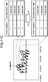
- the motion-candidate extracting unit 12 extracts peaks of p31, p32, p33, and p34 as the motion candidate points for the right leg.
- the motion-candidate extracting unit 12 performs the same processing indicated in FIG. 11A to FIG. 11D for the left leg, and extracts the motion candidate point.
- the motion candidate points of the right leg and the motion candidate points of the left leg are expressed in a graph in the left. Numerals above the motion candidate points expressed in the graph are candidate point numbers.
- the motion candidate points of the right leg and the motion candidate points of the left leg are given in a table in the right. In the table, the occurrence time, the start position, the end position, and the leg side are associated with the candidate point number.
- FIG. 12A to FIG. 12D illustrate a specific example of the direction-change-section determination processing according to the embodiment.
- the left-right-symmetry extracting unit 13 extracts whether the belonging leg is the same as that of the motion candidate point that occurs next as 0/1, for each motion candidate point.
- "0" indicates that the belonging legs are not the same, that is, alternate legs.
- "1" indicates that the belonging legs are the same. That is, the left-right-symmetry extracting unit 13 extracts a feature amount C1 that expresses that the left leg and the right leg alternately occur of each motion candidate point.
- the time-feature extracting unit 14 extracts an occurrence time interval until a motion candidate point occurring next, for each motion candidate point.
- the time-feature extracting unit 14 extracts a feature amount C2 that expresses successive occurrence within predetermine time, for each motion candidate point.
- the direction-change-section determining unit 16 extracts whether the rotation direction is the same as that of the motion candidate point occurring next as 0/1, for each motion candidate point. "1" indicates that the rotation directions are the same. "0” indicates that the rotation directions are not the same. That is, the direction-change-section determining unit 16 extracts a feature amount C3 that expresses occurrence in the same phase per motion candidate point.
- State 1 is a motion of starting a rotation (direction change).
- State 2 is a motion during a direction change.
- State 3 is a motion of finishing a rotation (direction change).
- State 4 is another motion (non-direction change motion).
- State 1, state 2, and state 3 correspond to the direction change motion.
- a state transition model and an observation model are defined in advance.
- the state transition model in this example is a probability model expressing which state is likely to appear next per state when assuming, in a direction change, a transition of state in motions that a motion of starting a rotation is followed by multiple rotation motions, and finally by a motion of finishing the rotation.
- the observation model is a probability model expressing what kind of feature amount is observed per state.
- the models can be determined heuristically or by using learning data. As for the latter case, data when a subject makes a direction change is collected, and model parameters are learned based on the data. For example, in this parameter learning, the Baum-Welch algorithm is applied.
- the direction-change-section determining unit 16 allocates the most probable state to each motion candidate point, by using the state transition model and the observation model.
- an allocated state S0 is set in a table.
- state 1, state 2, and state 3 are states of a direction change motion
- the direction-change-section determining unit 16 can determine the direction change motion per motion candidate point number by using the allocated state.
- a feature amount of each candidate point is observed only dependent on a state of a candidate point at that time.
- S (i) ) are defined in advance.
- the transition probability table expresses a probability per state transition from a state S (i) of the current candidate point to a state S (i+1) of a next candidate point table expressing.
- S (i) state 3) is 0.5.
- Equation (2) the observation model p(X (i)
- S (i) ) expresses a probability of a state S when a feature amount X is observed.
- X (i) is then expressed by ⁇ X 1 (i) , X 1 (i) , X 3 (i) ⁇ .
- X 1 (i) , X 1 (i) , X 3 (i) are the feature amounts C1, C2, C3 at the i-th candidate point, respectively.
- S (i) expresses a state at i-th candidate point (as the state number is 4, i is a natural number of 1 to 4).
- S i N x 1 i
- Equation (3) expresses the Gaussian model of the feature amount C1 in the state S.
- the second expression of N expresses the Gaussian model of the feature amount C in the state S.
- the third expression of N expresses the Gaussian model of the feature amount C3 in the state S.
- the Gaussian models of the feature amounts C1, C2, and C3 when the state S is a motion during a direction change are illustrated in FIG. 12D.
- the Gaussian model of the feature amount C1 there is a significantly high possibility that the feature amount C1 is "0" indicating the belonging leg appears alternately on the assumption that the leg on the opposite side moves in the following motion during a direction change.
- the Gaussian model of the feature amount C2 there is a high possibility that the time interval is small for the feature amount C on the assumption that a time interval until the following motion is small during a direction change.
- Application of the Viterbi algorithm enables the direction-change-section determining unit 16 to perform this estimation efficiently.
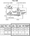
- FIG. 13A to FIG. 13C illustrate a specific example of the direction-change-feature extraction processing according to the embodiment.
- the direction-change-feature extracting unit 17 identifies a section of a direction change motion that has been determined by the direction-change-section determining unit 16. That is, the direction-change-feature extracting unit 17 acquires time information of a motion point in the section of the direction change motion.
- the direction-change-feature extracting unit 17 extracts (a) a rotation amount, (b) a rotation speed, (c) a rotation duration, (d) a forward movement speed, and (e) a time interval per motion point in the section of the direction change motion.
- the rotation amount can be acquired by calculating an integrated value of gyro in the traverse direction from a start time until an end time of a motion point.
- the rotation speed can be acquired by extracting the maximum value of gyro in the traverse direction from a start point until an end point of a motion point.
- the rotation duration can be acquired by calculating a section width from a start time until an end time of a motion point.
- the forward movement speed can be acquired by calculating the maximum value of gyro in the fore-and-aft direction from a start time until an end time of a motion point.
- the time interval can be acquired by calculating a time interval after a rotating motion of a current motion point ends until a next rotating motion starts.
- a lower diagram of FIG. 13B indicates extracted results of (a) the rotation amount, (b) the rotation speed, (c) the rotation duration, (d) the forward movement speed, and (e) the time interval for motion point numbers "1" to "6".
- the direction-change-feature extracting unit 17 calculates a statistic by using the feature amount of each motion point.
- the direction-change-feature extracting unit 17 calculates an average, a maximum value, a minimum value, a distribution, and a left-right ratio of the respective feature amounts (a) to (e).
- the direction-change-feature extracting unit 17 extracts the feature amounts (a) to (e) of a direction change start motion and a direction change end motion.
- the direction change start motion is a motion of a motion point of the motion point number "1".
- the direction change end motion is a motion of a motion point of the motion point number "6".
- the direction-change-feature extracting unit 17 calculates the number of motion points, a section width, a total rotation amount, a total advancement amount, a rotation amount/advancement amount ratio, and whether a still state section is present.
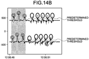
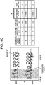
- FIG. 14A to FIG. 14C illustrate a specific example of the gait section identification processing according to the embodiment.
- the gait-section determining unit 19 identifies section before and after a direction change section. Subsequently, in an illustration on the right in FIG. 14A , the gait-section determining unit 19 acquires gyro data in the forward direction of both legs in the identified sections and detects peaks. The detected peaks are candidate points of gait motion.
- the gait-section determining unit 19 determines whether each candidate point includes a swing motion.
- the gait-section determining unit 19 determines that a swing motion is included when a maximum gait speed (height of the peak) of a candidate point exceeds a predetermined threshold (for example, the threshold R2), and determines as a candidate point.
- a predetermined threshold for example, the threshold R2
- the gait-section determining unit 19 identifies a section in which respective candidate points appear "alternately in left and right" and "successively" as a gait section.
- the gait-section determining unit 19 extracts the feature amounts C1 and C2 of each candidate point. That is, the feature amount C1 is extracted as a feature amount indicating that candidate points appear "alternately in left and right".
- the feature amount C1 is the feature amount expressing that the left leg and right leg alternately appear.
- the feature amount C2 is extracted as a feature amount indicating that candidate points appear "successively".
- the feature amount C2 is the feature amount expressing successive appearance in predetermined time.
- a case in which the gait-section determining unit 19 uses the hidden Markov model (HMM) to identify a gait section is explained. following four states are assumed as hidden states. State 1 is a motion of starting a gait. State 2 is a motion during a gait. State 3 is a motion of finishing a gait. State 4 is another motion (non-direction change motion). State 1, state 2, and state 3 correspond to the gait motion. A state transition model and an observation model are defined heuristically or by using learning data. The gait-section determining unit 19 allocates the most probable state to each candidate point by using the state transition model and the observation model. In this example, an allocated state S1 is set in a table.
- HMM hidden Markov model
- state 1 state 2, and state 3 are states of a gait motion
- the gait-section determining unit 19 can determine the gait motion per candidate point number by using the allocated state.
- the detailed application process is the same as that in the case of determining the direction change motion, explanation thereof is omitted.
- the gait-section determining unit 19 identifies a transition section.
- the transition gait section is a section of unstable walking until the walking is stabilized.
- a gait feature amount includes, for example, a time interval and a gait speed. In this example, a case in which a time interval is used as the gait feature amount is explained.
- the gait-section determining unit 19 calculates time intervals of four steps from a current motion point, and calculates a distribution of the time intervals of the four steps.
- the gait-section determining unit 19 determines that the gait has been stabilized when the distribution is smaller than a threshold, and identifies a section from a motion point of the first step in the section identified as the gait section to a motion point before the current motion point as the transition gait section.
- the current motion point is the motion point of the motion point number "1”
- the distributions of time intervals of four steps from the current motion point vary (D1). Therefore, an entry of stability for the current motion point is "x" indicating that it is not stable (D11).
- the current motion point is a motion point of the motion point number "3"
- the distributions of time intervals of four steps from the current motion point do not vary (D2).
- the gait-section determining unit 19 identifies a section from the motion point number "1" to the motion point number "2" as the transition gait section (D31).
- FIG. 15 illustrates a specific example of the gait-feature extraction processing according to the embodiment.
- the gait-feature extracting unit 20 extracts a feature amount of a motion point in the transition gait section that has been identified by the gait-section determining unit 19.
- the gait-feature extracting unit 20 extracts (v) a step length, (w) a gait speed, (x) a duration of a swing phase, (y) a foot lift amount, and (z) a left-right movement amount of each motion point in the transition gait section.
- the (v) step length can be acquired by calculating an integrated value of gyro in the forward direction from a start time until an end time of a motion point.
- the (w) gait speed can be acquired by extracting a maximum value of gyro in the forward direction from a start time until an end time of a motion point.
- the (x) duration of the swing phase can be acquired by calculating a section width from a start time until an end time of a motion point.
- the (y) foot lift amount can be acquired by calculating an integrated value of gyro in an upper limit direction from a start time until an end time of a motion point.
- the (z) left-right movement amount can be acquired by calculating an integrated value of gyro in a left-and-right direction from a start time until an end time of a motion point.
- FIG. 15 illustrates extracted results of (v) the step length, (w) the gait speed, (x) the duration of a swing phase, (y) the foot lift amount, and (z) the left-right movement amount for motion point numbers "1" and "2".
- the gait-feature extracting unit 20 can calculate a statistic by using the feature amount of each motion point. For example, the gait-feature extracting unit 20 can calculate an average, a maximum value, a minimum value, a distribution, and a left-right ratio of the respective feature amounts (v) to (z).
- the gait-feature extracting unit 20 can extract the feature amounts (v) to (z) of the first step and the second step.
- the gait-feature extracting unit 20 can calculate a section width of the transition gait section and the total number of gait steps (the number of transition gait steps) in the transition gait section.
- the gait-feature extracting unit 20 can extract a feature amount from between a direction change and a transition gait.
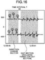
- FIG. 16 illustrates another specific example of the gait-feature extraction processing according to the embodiment.
- the gait-feature extracting unit 20 extracts a feature amount from between a direction change and a transition gait.
- the gait-feature extracting unit 20 extracts a time interval T from termination of the direction change until start of the transition gait.
- the gait-feature extracting unit 20 extracts a leg movement amount P of each leg from the termination of the direction change until the start of the transition gait.
- For the leg movement amount P a distribution amount of gyro in three axes of each leg in the time interval T is used, as an example.
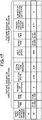
- FIG. 17 illustrates a specific example of the feature-amount storage processing according to the embodiment.
- the feature-amount storage unit 21 stores a feature amount in a direction change section and a feature amount in a transition gait section in the data storage unit 23 per direction change section.
- a result of storing feature amounts in the direction change section and feature amounts in the transition gait section of a direction-change section number "34" is given.
- the feature amounts in the direction change section are the statistics indicated in the lower diagram in FIG. 13C .
- the feature amounts in the transition gait section are statistics of the feature amounts of all the motion points illustrated in FIG. 15 .
- FIG. 18 illustrates a specific example of the feature-amount visualization processing according to the embodiment.
- the feature-amount visualizing unit 22 visualizes various kinds of feature amounts chronologically per month, with reference to a predetermined day, for a section thereafter.
- a feature amount to be visualized is the number of motions needed to perform a direction change.
- the predetermined day is set to a day of treatment.
- the feature-amount visualizing unit 22 receives the day of treatment and visualizes the number of motions need to perform a direction change per month, with reference to this day, for sections before and after the section.
- the number of motions per month to be visualized can be the number of motions on a day that has been determined in each month, or can be an average of the number of motions of each month.
- the feature-amount visualizing unit 22 enables to detect that motor deterioration (particularly in a balancing function) is suspected as the number of motions needed to perform a direction change exceeds a risk level in June after the day of treatment, for example.
- the information processing apparatus 1 extracts a point at which a motion of leg rotation about an axis of a direction of gravity occurs as a motion candidate in respective data of the sensor device 2 used for a left leg and the sensor device 3 used for a right leg.
- the information processing apparatus 1 determines extracted motion candidates as a direction change motion when directions of the rotation are the same, a motion candidate of a left leg and a motion candidate of a right leg appear alternately, and appear chronically successively.
- the information processing apparatus 1 extracts a feature of the direction change motion by using data acquired by the sensors. According to this configuration, the information processing apparatus 1 can extract a feature amount of a direction change motion by using only the sensor devices 2, 3 used for legs on respective sides highly accurately.
- the information processing apparatus 1 detects a point in which a rotation amount of leg between a time when one foot comes off the ground until a time of landing is larger than a first threshold by using data of at least one axis acquired by the sensor devices 2, 3, and extracts the detected point as a motion candidate of a direction change. According to this configuration, the information processing apparatus 1 can extract a motion candidate of a direction change that is used to extract a feature amount of a direction change motion by using only the sensor devices 2, 3 used for legs on respective sides.
- the information processing apparatus 1 groups, when there are points that appear successively in the same leg in predetermined time in a point extracted as a motion candidate, the successive points as one unit, and extracts the grouped point as one motion candidate of a direction change. According to this configuration, the information processing apparatus 1 can extract a motion candidate of one step when a leg on the same side is turned to make a direction change even when the leg on the same side is unstable.
- the information processing apparatus 1 extracts information including at least one of a rotation amount in the traverse direction, a rotation speed, a rotation duration, and an advancement amount to the forward direction, as a feature amount of a direction change motion, for a point of a direction change motion. According to this configuration the information processing apparatus 1 can extract a feature amount of a direction change motion highly accurately.
- the information processing apparatus 1 determines a point in which a rotation amount in the traverse direction is smaller than the first threshold and larger than the second threshold that is smaller than the first threshold as a mild direction change motion, out of points occurring right after a determined direction change motion.
- the information processing apparatus 1 extracts a feature amount of the determined mild direction change motion by using respective data of the sensor devices 2, 3.
- the information processing apparatus 1 determines a mild direction change motion that is estimated to be walking while turning to change a direction, thereby enabled to extract a feature amount of a mild direction change highly accurately.
- the information processing apparatus 1 extracts a point in which a rotation amount to the forward direction is equal to or larger than the threshold R1 in a section between termination of a direction change motion until start of a next direction change motion as a motion candidate of a gait.
- the information processing apparatus 1 determines points that are larger than the threshold R2 smaller than the threshold R1 as a start and an end of a gait section, in before and after the extracted motion candidate of a gait. According to this configuration, the information processing apparatus 1 can determine a gait section accurately by determining a start and an end of the gait section.
- the information processing apparatus 1 determines sections before a section in which a distribution of time intervals of the predetermined number of sequential points become equal to or lower than a threshold as a transition gait section that indicates that it is an unstable gait section, in a gait section. According to this configuration, the information processing apparatus 1 can determine a transition gait section until it becomes a stable gait in which walking is stable accurately.
- the information processing apparatus 1 extracts a feature amount of a transition gait section by using data of the respective sensor devices 2, 3. According to this configuration, the information processing apparatus 1 can extract a feature amount of a transition gait section highly accurately.
- the information processing apparatus 1 extracts a feature amount of a direction change motion and a gait motion of a subject by using data of the sensor devices 2, 3 that are worn on respective legs of the subject.
- the processing of extracting a feature amount of a direction change motion and a gait motion of a subject can be performed by the sensor device 2 or the sensor device 3.
- the sensor device 2 can be configured to extract a feature amount of a direction change motion and a gait motion of a subject by using data acquired by itself and by the sensor device 3.
- respective components of the illustrated devices are not necessarily physically configured as illustrated. That is, specific forms of distribution and integration of the respective devices are not limited to the ones illustrated, and all or a part thereof can be configured to be distributed or integrated functionally or physically in arbitrary units according to various kinds of loads, usage conditions, and the like.
- the gait-section determining unit 19 can be distributed to a determining unit that determines a stable gait section, and a determining unit that determines a transition gait section.
- the before-and-after-section identifying unit 18 can be distributed to a determining unit that determines a before-and-after section and an extracting unit that extracts a feature amount of the before-and-after section.
- the left-right-symmetry extracting unit 13, the time-feature extracting unit 14, and the phase-feature extracting unit 15 can be integrated. Moreover, it can be configured to connect the data storage unit 23 to the information processing apparatus 1 as an external device through a network.
- FIG. 19 illustrates one example of a computer that executes the information processing program.
- a computer 200 includes a CPU 203 that executes various kinds of arithmetic processing, an input device 215 that accepts an input of data from a user, and a display control unit 207 that controls a display device 209. Furthermore, the computer 200 includes a drive device 213 that reads a program and the like from a recording medium, and a communication control unit 217 that communicates data with other computers through a network. Moreover, the computer 200 includes a memory 201 that stores various kinds of information temporarily, and an HDD 205. The memory 201, the CPU 203, the HDD 205, the display control unit 207, the drive device 213, the input device 215, and the communication control unit 217, are connected to each other through a bus 219.
- the drive device 213 is, for example, a device for a removable disk 211.
- the HDD 205 stores an information processing program 205a and information-processing-related information 205b.
- the CPU 203 reads the information processing program 205a, and develops it in the memory 201 to execute it as a process.
- the process corresponds to the respective functional units of the information processing apparatus 1.
- the information-processing-related information 205b corresponds to the data storage unit 23.
- the removable disk 211 stores various information such as the information processing program 205a.
- the information processing program 205a is not necessarily stored in the HDD 205 from the beginning.
- it can be stored in a "portable physical medium", such as a flexible disk (FD), a CD-ROM, a DVD, a magnetooptical disk, or an IC card, that is inserted into the computer 200, and the computer 200 can read the information processing program 205a from these to execute it.
- a "portable physical medium” such as a flexible disk (FD), a CD-ROM, a DVD, a magnetooptical disk, or an IC card
Landscapes
- Health & Medical Sciences (AREA)
- Life Sciences & Earth Sciences (AREA)
- Engineering & Computer Science (AREA)
- Physics & Mathematics (AREA)
- Biomedical Technology (AREA)
- Public Health (AREA)
- Medical Informatics (AREA)
- General Health & Medical Sciences (AREA)
- Biophysics (AREA)
- Veterinary Medicine (AREA)
- Animal Behavior & Ethology (AREA)
- Surgery (AREA)
- Molecular Biology (AREA)
- Heart & Thoracic Surgery (AREA)
- Pathology (AREA)
- Remote Sensing (AREA)
- Radar, Positioning & Navigation (AREA)
- Physiology (AREA)
- Artificial Intelligence (AREA)
- Dentistry (AREA)
- Oral & Maxillofacial Surgery (AREA)
- Computer Vision & Pattern Recognition (AREA)
- General Physics & Mathematics (AREA)
- Psychiatry (AREA)
- Signal Processing (AREA)
- Automation & Control Theory (AREA)
- General Business, Economics & Management (AREA)
- Evolutionary Computation (AREA)
- Fuzzy Systems (AREA)
- Mathematical Physics (AREA)
- Business, Economics & Management (AREA)
- Epidemiology (AREA)
- Primary Health Care (AREA)
- Computer Networks & Wireless Communication (AREA)
- Image Analysis (AREA)
- Measurement Of The Respiration, Hearing Ability, Form, And Blood Characteristics Of Living Organisms (AREA)
- Navigation (AREA)
Abstract
Description
- The present invention relates to an information processing system and the like.
- A technique of detecting gait initiation and gait termination by using sensor on both legs has conventionally been known. For example, there is a technique of detecting a sign of gait initiation based on angles of a back and a knee and then detecting toe-off based on a foot pressure on a shoe sole, thereby detecting gait initiation (for example, refer to Non Patent Document 1).
- Furthermore, there is a technique in which a mobile terminal detects, when a walker holding the mobile terminal in his/her hand changes the direction of his/her steps, the direction change (for example, refer to Patent Document 1). In the technique, a mobile terminal including an acceleration sensor and a GPS unit determines that a walker has changed the direction of his/her steps when the following conditions are met. The conditions specifically are that a first azimuth difference between a first traveling direction at a first time point and a third traveling direction at a third time point is equal to or larger than an angle threshold, and that a second azimuth difference between a second traveling direction at a second time point and a fourth traveling direction at a fourth time point is equal to or larger than the angle threshold.
-
- Patent Document 1: Japanese Laid-open Patent Publication no.
2009-75036 - Patent Document 2: Japanese Laid-open Patent Publication No.
10-113343 - Patent Document 3: Japanese Laid-open Patent Publication No.
2008-027429 - Patent Document 4: Japanese Laid-open Patent Publication No.
2009-150711 - Patent Document 5: Japanese Laid-open Patent Publication No.
2010-223829 - Non Patent Document 1: "Automated detection of gait initiation and termination using wearable sensors Medical Engineering & Physics, Vol. 35, Issue 12, pp. 1713-1720"
- However, there has been a problem in conventional techniques that a feature amount of a direction change motion cannot be extracted highly accurately only with sensors on both legs.
- For example, in the technique in which a mobile terminal detects a direction change, the mobile terminal can detect a section of the direction change based on changes in the azimuth difference by using a sensor at a position at which the mobile terminal is held in a hand, but cannot detect a feature amount of individual direction change motions with high accuracy. This is because the sensor positioned at a position at which the terminal is held in a hand cannot detect individual step actions when a direction change is made with significantly small steps.
- If the technique of detecting a gait initiation with sensors on both legs and the technique in which a mobile terminal detects a direction change are combined, a feature amount of a direction change motion can be extracted; however, sensors are necessary to be worn not only on both legs but also on an upper body.
- In one aspect, it is an object to extract a feature amount of a direction change motion highly accurately only with sensors on both legs.
- An information processing system disclosed in the present application includes: a first motion sensor that is used for a left leg; a second motion sensor that is used for a right leg; and an information processing unit configured to process data acquired by the sensors. The information processing unit includes: a motion-candidate extracting unit configured to extract a point at which a motion of rotation of a leg about an axis in a direction of gravity occurs in the data acquired by the sensors, as a motion candidate of a direction change; a direction-change-motion determining unit configured to determine a plurality of motion candidates extracted by the motion-candidate extracting unit as a direction change motion when directions of the rotation are identical, and a motion candidate of the left leg and a motion candidate of the right leg alternately appear chronically successively; and a feature extracting unit configured to extract a feature of the direction change motion that is determined by the direction-change-motion determining unit, by using the data acquired by the sensors.
- According to one embodiment, a feature amount of a direction change motion can be extracted highly accurately only with sensors on both legs.
-
-
FIG. 1 is a functional block diagram illustrating a configuration of an information processing system according to an embodiment. -
FIG. 2A is a diagram for explaining directions of axes of a sensor device. -
FIG. 2B is a diagram illustrating one example of wearing of the sensor devices. -
FIG. 3 is a diagram for explaining direction-change section determination according to the embodiment. -
FIG. 4 is a diagram illustrating one example of peak detection. -
FIG. 5 is a diagram for explaining gait section determination according to the embodiment. -
FIG. 6 is a flowchart of entire information processing according to the embodiment. -
FIG. 7A is a flowchart of direction-change-section extraction processing according to the embodiment. -
FIG. 7B is a flowchart of the direction-change-section extraction processing according to the embodiment. -
FIG. 7C is a flowchart of the direction-change-section extraction processing according to the embodiment. -
FIG. 8 is a flowchart of direction-change feature-amount-extraction processing according to the embodiment. -
FIG. 9A is a flowchart of transition -gait-section extraction processing according to the embodiment. -
FIG. 9B is a flowchart of the transition -gait-section extraction processing according to the embodiment. -
FIG. 9C is a flowchart of the transition -gait-section extraction processing according to the embodiment. -
FIG. 10 is a flowchart of transition-gait-feature extraction processing according to the embodiment. -
FIG. 11A illustrates a specific example of motion-candidate extraction processing according to the embodiment. -
FIG. 11B illustrates a specific example of the motion-candidate extraction processing according to the embodiment. -
FIG. 11C illustrates a specific example of the motion-candidate extraction processing according to the embodiment. -
FIG. 11D illustrates a specific example of the motion-candidate extraction processing according to the embodiment. -
FIG. 11E illustrates a specific example of the motion-candidate extraction processing according to the embodiment. -
FIG. 12A illustrates a specific example of direction-change-section determination processing according to the embodiment. -
FIG. 12B illustrates a specific example of the direction-change-section determination processing according to the embodiment. -
FIG. 12C illustrates a specific example of the direction-change-section determination processing according to the embodiment. -
FIG. 12D illustrates a specific example of the direction-change-section determination processing according to the embodiment. -
FIG. 13A illustrates a specific example of direction-change-feature extraction processing according to the embodiment. -
FIG. 13B illustrates a specific example of the direction-change-feature extraction processing according to the embodiment. -
FIG. 13C illustrates a specific example of the direction-change-feature extraction processing according to the embodiment. -
FIG. 14A illustrates a specific example of gait section identification processing according to the embodiment. -
FIG. 14B illustrates a specific example of the gait section identification processing according to the embodiment. -
FIG. 14C illustrates a specific example of the gait section identification processing according to the embodiment. -
FIG. 14D illustrates a specific example of the gait section identification processing according to the embodiment. -
FIG. 15 illustrates a specific example of gait-feature extraction processing according to the embodiment. -
FIG. 16 illustrates another specific example of the gait-feature extraction processing according to the embodiment. -
FIG. 17 illustrates a specific example of feature-amount storage processing according to the embodiment. -
FIG. 18 illustrates a specific example of feature-amount visualization processing according to the embodiment. -
FIG. 19 illustrates one example of a computer that executes an information processing program. - Embodiments of an information processing system, an information processing program, and an information processing method disclosed in the present application are explained in detail below based on the accompanying drawings. The embodiments are not intended to limit the present invention.
-
FIG. 1 is a functional block diagram illustrating a configuration of an information processing system according to an embodiment. As illustrated inFIG. 1 , aninformation processing system 9 includes aninformation processing apparatus 1, andsensor devices information processing apparatus 1 is connected to each of thesensor device 2 and thesensor device 3. - The
sensor device 2 is an angular velocity sensor (gyro sensor) around three axes that are perpendicular to each other, and is worn, for example, on a left leg of a subject. Axis directions of thesensor device 2 are explained referring toFIG. 2A . -
FIG. 2A is a diagram for explaining directions of axes of a sensor device. As illustrated in a diagram, "WHEN VIEWED FROM TOP" inFIG. 2A , an angular velocity about a Z-axis is to be a displacement value along with rotation in a traverse (left-right) direction in walking of the subject. That is, it is a rotation amount in a left-right direction relative to a worn posture of the sensor device at a predetermine time point and, for example, a rotation amount in a rightward direction is plus (forward direction), and a rotation amount in a leftward direction is minus. As illustrated in a diagram, "WHEN VIEWED FROM RIGHT SIDE" inFIG. 2A , an angular velocity about an X-axis is to be a displacement value along with rotation in a fore-and-aft direction in walking of the subject. That is, it is a rotation amount in a fore-and-aft direction relative to the worn posture of thesensor device 2 at a predetermined time point, and a rotation amount in a backward direction (lift-up direction) is plus (forward direction), and a rotation amount in a frontward direction (forward-leaning direction) is minus. An angular velocity about a Y-axis is to be a displacement value along with rotation in a body axis direction in walking of the subject. That is, it is a rotation amount in the left-right direction relative to the worn posture of the sensor device at a predetermined time point, and a rotation amount in a rightward direction is plus, and a rotation amount in a leftward direction is minus. Thesensor device 2 can be an acceleration sensor that detects acceleration in three axes perpendicular to each other. Moreover, thesensor device 2 can include a gyro sensor and an acceleration sensor. In the following, explanation is given assuming that thesensor device 2 is a gyro sensor. - The
sensor device 2 includes adata acquiring unit 21 and adata transmitting unit 22. Thedata acquiring unit 21 acquires gyro data. Thedata transmitting unit 22 transmits the gyro data acquired by thedata acquiring unit 21 to theinformation processing apparatus 1. - The
sensor device 3 is the same device as thesensor device 2, and is worn, for example, on a right leg of the subject. As the function thereof is the same as that of thesensor device 2, explanation thereof is omitted. - An example of wearing of the
sensor devices FIG. 2B. FIG. 2B is a diagram illustrating one example of wearing of the sensor devices. As illustrated inFIG. 2B , thesensor devices sensor device 2 is worn on the left leg of the subject, and thesensor device 3 is worn on the right leg of the subject. Thesensor devices information processing apparatus 1, and transmit various kinds of data to theinformation processing apparatus 1 according to a direction change motion and a gait motion of the subject. - Referring back to
FIG. 1 , theinformation processing apparatus 1 extracts feature amounts of the direction change motion and the gait motion of the subject by using only data from thesensor devices information processing apparatus 1 includes adata acquiring unit 11, a motion-candidate extracting unit 12, a left-right-symmetry extracting unit 13, a time-feature extracting unit 14, a phase-feature extracting unit 15, a direction-change-section determining unit 16, and a direction-change-feature extracting unit 17. In addition, theinformation processing apparatus 1 includes a before-and-after-section identifying unit 18, a gait-section determining unit 19, a gait-feature extracting unit 20, a feature-amount storage unit 21, a feature-amount visualizing unit 22, and a data storage unit 23. Thesensor devices information processing apparatus 1 is one example of an information processing unit. - The
data acquiring unit 11 receives various kinds of data that are transmitted respectively from thesensor devices data acquiring unit 11 receives 60 samples each of the various kinds of data in one second, and accumulates the received various kinds of data. The various kinds of data include a rotation amount in a traverse (left-right) direction, a rotation amount in a fore-and-aft direction, and a rotation amount of a body axis. The various kinds of data are accumulated in the data storage unit 23 every each time point. - Having acquired a start instruction to extract a feature of a direction change, the
data acquiring unit 11 reads various kinds of data of a corresponding subject from the data storage unit 23 based on the acquired instruction. Thedata acquiring unit 11 outputs the read various kinds of data to the motion-candidate extracting unit 12. - The motion candidate extracting unit 12 extracts a portion at which a rotation amount in a traverse direction is larger than a first threshold, as a motion candidate. For example, the motion-candidate extracting unit 12 detects a peak from an angular velocity toward a traverse direction from among the various kinds of data that are output from the
data acquiring unit 11. The peak detection is performed, applying a lowpass filter, such as a Butterworth filter, to the angler velocity data. The motion-candidate extracting unit 12 extracts a portion around this peak in one unit as a motion candidate of the direction change when the rotation amount toward the traverse direction around this peak is larger than the first threshold. When peaks of rotation in the same traverse direction appear successively in the same leg within predetermined time, the motion-candidate extracting unit 12 can group these peaks and detect as one peak. This is because when a human takes a step, motion is complicated in rotation in the traverse direction compared to movement to a forward direction and peaks are likely to appear successively. Thus, the motion-candidate extracting unit 12 can extract one motion candidate of the direction change per step. - The left-right-symmetry extracting unit 13 compares the motion candidate that is extracted by the motion-candidate extracting unit 12 with a next previous motion candidate, and extracts whether an actin candidate of the left leg and a motion candidate of the right leg appear alternately.
- The time-feature extracting unit 14 extracts a time interval between the motion candidate that is extracted by the motion-candidate extracting unit 12 and a next previous motion candidate.
- The phase-
feature extracting unit 15 extracts whether rotation in the traverse direction of the motion candidate that is extracted by the motion-candidate extracting unit 12 is in the same direction (same phase) as a next previous motion candidate. - The direction-change-
section determining unit 16 determines a section in which the feature extracted by the time-feature extracting unit 14, the feature extracted by the left-right-symmetry extracting unit 13, and the feature extracted by the phase-feature extracting unit 15 satisfy a predetermined condition as a direction change section. Specifically, the direction-change-section determining unit 16 determines a section of a motion candidate in which the rotations in the traverse direction are in the same direction, and the left leg and the right leg rotate alternately, and that appears chronically successively, as the direction change motion, out of plural motion candidates extracted by the motion-candidate extracting unit 12. - Note that the method of determining the direction change section by the direction-change-
section determining unit 16 is not limited to the method by condition-based determination described above. The direction-change-section determining unit 16 can determine the direction change section by probability by using the hidden Markov model (HMM) or the like. The method of determining the direction change section by using the hidden Markov model (HMM) is explained later. - Direction-change section determination according to the embodiment is explained, referring to
FIG. 3. FIG. 3 is a diagram for explaining the direction-change section determination according to the embodiment. As expressed by solid lines in an upper diagram and a lower diagram inFIG. 3 , the angular velocity in the traverse direction of the left leg transmitted from thesensor device 2 and the angular velocity in the traverse direction of the right leg transmitted from thesensor device 3 are indicated chronologically in graphs. Doted lines in the graphs indicate the angular velocity in the forward direction. - The motion-candidate extracting unit 12 applies a lowpass filter to a rotation amount in the traverse direction to detect a peak, and extracts, when a rotation amount in the traverse direction from a start of the peak until an end of the peak is larger than the first threshold, a portion around this peak in one unit as a motion candidate of the direction change. In this example, the rotation amount in the traverse direction of peaks p1 to p7 are larger than the first threshold. Therefore, the motion-candidate extracting unit 12 extracts the respective peaks p1 to p7 as motion candidates of the direction change.
- The time-feature extracting unit 14 extracts a time interval between the motion candidate that is extracted by the motion-candidate extracting unit 12 and a next previous motion candidate. In this example, a time interval between the peaks p1 and p2 being motion candidates is extracted as t1, as an example. Similarly, a time interval between the peaks p2 and p3 being motion candidates is extracted. A time interval between the peaks p3 and p4 as motion candidates is extracted. A time interval between the peaks p4 and p5 being motion candidates is extracted. A time interval between the peaks p5 and p6 being motion candidates is extracted.
- The left-right-symmetry extracting unit 13 compares the motion candidate that is extracted by the motion-candidate extracting unit 12 with a next previous motion candidate, and extracts whether a motion candidate of the left leg and a motion candidate of the right leg appear alternately. In this example, as the peak p2 is a motion candidate of the left leg and the next previous motion candidate, the peak p1 is a motion candidate of the right leg, alternate appearance is extracted. Similarly, as the peak p3 is a motion candidate of the right leg and the next previous motion candidate, the peak p2 is the motion candidate of the left leg, alternate appearance is extracted. As the peak p4 is a motion candidate of the left leg and the next previous motion candidate, the peak p3 is the motion candidate of the right leg, alternate appearance is extracted. As the peak p5 is a motion candidate of the right leg and the next previous motion candidate, the peak p4 is the motion candidate of the left leg, alternate appearance is extracted. As the peak p6 is a motion candidate of the left leg and the next previous motion candidate, the peak p5 is the motion candidate of the right leg, alternate appearance is extracted. As the peak p7 is a motion candidate of the left leg and the next previous motion candidate, the peak p6 is the motion candidate of the right leg, alternate appearance is extracted.
- The phase-
feature extracting unit 15 extracts whether rotation in the traverse direction of the motion candidate that is extracted by the motion-candidate extracting unit 12 is in the same direction (same phase) as that of the next previous motion candidate. In this example, as signs of the rotation amounts of the peaks p1 to p7 are all plus, it is extracted that all of them is in the same direction. Therefore, it is extracted that the peaks p1 to p7 are of the same direction (same phase). - The direction-change-
section determining unit 16 determines a section in which the feature extracted by the time-feature extracting unit 14, the feature extracted by the left-right-symmetry extracting unit 13, and the feature extracted by the phase-feature extracting unit 15 satisfy a predetermined condition as a direction change section. Specifically, the direction-change-section determining unit 16 determines a section of a motion candidate in which the rotations in the traverse direction are in the same direction, and the left leg and the right leg rotate alternately, and that appears chronically successively, as the direction change motion, out of plural motion candidates extracted by the motion-candidate extracting unit 12. In this example, it is determined that the peaks p1 to p7 are motion candidates that appear chronically successively based on the feature extracted by the time-feature extracting unit 14. it is determined that the peaks p1 to p7 are motion candidates in which the left leg and the right leg rotate alternately (j2) based on the feature extracted by the left-right-symmetry extracting unit 13. It is determined that the peaks p1 to p7 are motion candidates of the same phase based on the feature extracted by the phase-feature extracting unit 15 (j3). Therefore, the section of the peaks p1 to p7 of the motion candidates is determined as the direction change section. - A method of detection a peak detected by the motion-candidate extracting unit 12 is explained, referring to
FIG. 4. FIG. 4 is a diagram illustrating one example of peak detection. As illustrated inFIG. 4 , when a human takes a step, motion is often complicated in rotation in the traverse direction compared to movement to a forward direction. When the motion is complicated in rotation in the traverse direction, multiple peaks appear successively. An example of a case in which successive multiple peaks occur is when a leg rotates just before landing in a period from a pre-foot-off to a post-foot-strike. The pre-foot-off is before a foot is taken off. The post-foot-strike is after a foot strikes on. In this example, it is assumed that multiple peaks p11, p12 occur when one leg is rotated just one step in the traverse direction. - In this case, the motion candidate extracting unit 12 groups, when peaks of rotation in the same traverse direction successively appear in the same leg within predetermined time, these peaks. In this example, the predetermined time is 100 ms. As the peak p11 and the peak p12 are of the same leg, and are rotations in the same traverse direction, and appear successively. Furthermore, an interval between the peak p11 and the peak p12 is smaller than 100 ms. Therefore, the motion-candidate extracting unit 12 groups the peak p11 and the peak p12 as a peak p10. Thus, the motion-candidate extracting unit 12 can extract one motion candidate of the direction change of one step. Note that multiple peaks that appear successively in predetermine time is referred to as "multiplex peaks", and grouping multiplex peaks is referred to as "chunking processing".
- Referring back to
FIG. 1 , the direction-change-feature extracting unit 17 extracts a feature of a direction change motion that has been determined by the direction-change-section determining unit 16, using data stored in the data storage unit 23. For example, the direction-change-feature extracting unit 17 extracts features relating to (A) how fast a direction change was done, (B) how large it was rotated, (C) whether it could rotate large from a start, (D) whether a direction change could be done stably, (E) whether a still state occurred during a direction change, and (F) how asymmetric between a left leg and a right leg. As an example of (A), <1> a frequency of direction change motions during a direction change is extracted. <2> a maximum duration of a direction change motion during a direction change is extracted. <3> An average duration of a direction change motion during a direction change is extracted. As an example of (B), <4> a maximum rotation amount of a direction change motion during a direction change is extracted. <5> An average rotation amount of a direction change motion during a direction change is extracted. As an example of (C), <6> a rotation amount of a first direction change motion during a direction change is extracted. As an example of (D), <7> an interval between adjacent direction change motions during a direction change is extracted. <8> A lurch in a traverse direction right after foot strike is extracted. As an example of (E), <9> whether a still state is present, or a duration of a still state when a still state is present during a direction change is extracted. The features of a direction change motion that is extracted by the direction-change-feature extracting unit 17 are one example, and are not limited thereto. - The before-and-after-section identifying unit 18 identifies a peak, the rotation amount in the traverse direction is equal to or smaller than a first threshold and equal to or larger than a second threshold out of peaks that occur right after (or right before) a direction change section that has been determined by the direction-change-
section determining unit 16. The second threshold is a threshold smaller than the first threshold. That is, right after (or right before) a direction change motion is determined, a direction change can be made while walking. Therefore, the before-and-after-section identifying unit 18 identifies peaks when a direction change is made while walking. Such a direction change that occurs before and after a direction change is referred to as "mild direction change". Thus, a length of a section in which the identified mild direction change continues is extracted as a feature amount, and the before-and-after-section identifying unit 18 can thereby determine a difficulty of a direction change. Moreover, the before-and-after-section identifying unit 18 can determine a lurch after a direction change by extracting whether a direction of a mild direction change in the traverse direction is an opposite direction to a direction change right before that. - The gait-
section determining unit 19 identifies a gait section candidate between two direction change sections. For example, the gait-section determining unit 19 detects peaks from an angular velocity to a forward direction between two direction change sections, and identifies a peak, the rotation amount of which to the forward direction is equal to or larger than a threshold R1 out of the detected peaks. The gait-section determining unit 19 identifies a section in which the identified peaks successively occur in a short period of time as a gait section candidate. The gait-section determining unit 19 identifies a peak, the rotation amount to the forward direction of which is smaller than the threshold R1 and equal to or larger than the threshold R2 before and after the gait section candidate. The threshold R2 is a threshold smaller than the threshold R1. Such a section of peaks identified before and after a gait section candidate is referred to as "transition gait section". In other words, the "transition gait section" is a section of unstable walking until the walking is stabilized. The gait-section determining unit 19 determines the first peak in a transition gait section as the "first step", and determines the last peak as the "last step". A section including the transition gait section and the gait section candidate is referred to as "gait section" for convenience. - The method of determining the "gait section" is not limited thereto. The gait-
section determining unit 19 can determine the gait section by using the hidden Markov model (HMM). The method of determining the "gait section" by using the hidden Markov model (HMM) is described later. Furthermore, as the "transition gait section" is an unstable section in terms of walking and a section of the mild direction change is an unstable section in terms of direction change, these sections can be determined in a duplicated manner. Moreover, the method of determining the transition gait section is not limited thereto. As another example, the gait-section determining unit 19 can determine a section from the first step until first several steps (for example, four steps) are completed as the transition gait section, out of a section that has been determined as the gait section. A method of determining the transition gait section by using a distribution of time intervals of peaks is described later. - The gait-
feature extracting unit 20 extracts a feature of the transition gait section that has been identified by the gait-section determining unit 19 by using data stored in the data storage unit 23. For example, the gait-feature extracting unit 20 extracts features relating to (a) how fast it turned into stable walking, and (b) with how few lurch, it turned into stable walking. As an example of (a), time and the number of steps until it turned into stable walking are extracted. As an example of (b), a rotation amount in a traverse direction until it turned into stable walking is extracted. - The feature-
amount storage unit 21 stores feature amounts in the direction change section and the transition gait section chronologically in the data storage unit 23. For example, the feature-amount storage unit 21 stores various kinds of feature amount of the direction change section extracted by the direction-change-feature extracting unit 17 and various kinds of feature amount of the transition gait section extracted by the gait-feature extracting unit 20 in order of occurrence in the data storage unit 23. - The feature-
amount visualizing unit 22 visualizes various kinds of feature amount stored in the data storage unit 23 in chronological order. For example, when the subject is a patient, the feature-amount visualizing unit 22 visualizes statistical values of various kinds of feature amount per month for sections before and after relative to the day on which the patient is treated, to monitor the treatment progress. An example of the feature amount includes the number of times of direction change motion during a direction change. - Gait section determination according to the embodiment is explained, referring to
FIG. 5. FIG. 5 is a diagram for explaining the gait section determination according to the embodiment. As illustrated in upper and lower diagrams inFIG. 5 , the angular velocity in the forward direction of the left leg transmitted from thesensor device 2 and the angular velocity in the forward direction of the right leg transmitted from thesensor device 3 are indicated chronologically in graphs per time. - The gait-
section determining unit 19 applies a lowpass filter to the rotation amount in the forward direction between two direction change sections to detect peaks, and identifies a peak, the rotation amount in the forward direction of which is equal to or larger than the threshold R1. In this example, respective rotation amounts of peaks p21 to p27 are equal to or larger than the threshold R1. Therefore, the gait-section determining unit 19 identifies a section in which the peaks p21 to p27 successively occur in a short period of time as a gait section candidate. - The gait-
section determining unit 19 identifies peaks before and after the gait section candidate, and identifies a peak, the rotation amount in the forward direction of which is smaller than the threshold R1 and equal to or larger than the threshold R2 out of the identified peaks. In this example, rotation amounts of peak p20 and p30 in the forward direction are smaller than the threshold R1 and equal to or larger than the threshold R2. Therefore, the gait-section determining unit 19 determines that the peak p20 before the gait section candidate as the first one step. The gait-section determining unit 19 determines the peak p30 after the gait section candidate as the last one step. - Next, a flowchart of entire information processing according to the embodiment is explained, referring to
FIG. 6. FIG. 6 is a flowchart of entire information processing according to the embodiment. It is assumed that thedata acquiring unit 11 has accepted a start instruction to extract a feature of a direction change for a specific subject. It is assumed that gyro sensor data from thesensor devices - First, the
data acquiring unit 11 acquires gyro sensor data corresponding to the specific subject from the data storage unit 23 (step S11). The direction-change-section determining unit 16 extracts a direction change section (step S12). A detailed flowchart is described later. - The direction-change-feature extracting unit 17 extracts a feature amount of the direction change (step S13). A detailed flowchart is described later.
- The before-and-after-section identifying unit 18 identifies sections before and after the direction change section (step S14). For example, the before-and-after-section identifying unit 18 identifies a peak, the rotation amount in the traverse direction of which is equal to or smaller than the first threshold and equal to or larger than the second threshold out of peaks that occur right after the direction change section. That is, the before-and-after-section identifying unit 18 identifies a section of a mild change of direction (mild direction change) that occurs before and after the direction change section.
- The gait-
section determining unit 19 extracts a transition gait section (step S15). A detailed flowchart is described later. - The gait-
feature extracting unit 20 extracts a feature amount of transition gait from the transition gait section (step S16). A detailed flow chart is described later. - The feature-
amount storage unit 21 stores feature amounts of a direction change and a transition gait in a DB (database) (step S17). The feature-amount storage unit 21 stores various kinds of feature amount of the direction change section extracted by the direction-change-feature extracting unit 17 and various kinds of feature amount of the transition gait section extracted by the gait-feature extracting unit 20 in order of occurrence in the data storage unit 23. - The feature-
amount visualizing unit 22 visualizes a feature amount (step S18). For example, the feature-amount visualizing unit 22 visualizes various kinds of feature amount stored in thedata storage unit 21 in chronological order. - Next, a flowchart of direction-change-section extraction processing according to the embodiment is explained, referring to
FIG. 7A to FIG. 7C. FIG. 7A to FIG. 7C are flowcharts of the direction-change-section extraction processing according to the embodiment. - As illustrated in
FIG. 7A , the motion-candidate extracting unit 12 extracts a motion candidate point from traverse direction gyro data of the left leg (step S21). For example, the motion-candidate extracting unit 12 detects a peak from the rotation amount in the traverse direction of the left leg out of data stored in the data storage unit 23. - The motion-candidate extracting unit 12 extracts a motion candidate point from traverse direction gyro data of the right leg (step S22). For example, the motion-candidate extracting unit 12 detects a peak from the rotation amount in the traverse direction of the right leg out of data stored in the data storage unit 23.
- The motion-candidate extracting unit 12 performs chunking processing of multiplex peaks (step S23). That is, the motion-candidate extracting unit 12 groups, when peaks of rotation in the same traverse direction appear successively in the same leg within predetermined time (for example, 100 ms), the peaks into one unit of peak.
- The motion-candidate extracting unit 12 sets an
initial value 1 to an index i (step S24). The motion-candidate extracting unit 12 calculates a rotation amount in the traverse direction at an i-th motion candidate point (step S25). The motion-candidate extracting unit 12 excludes the calculated rotation amount in the traverse direction when it is equal to or smaller than a threshold (step S26). The threshold herein is, for example, the first threshold described above. - The motion-candidate extracting unit 12 determines whether the index i is smaller than a total number N of motion candidate points (step S27). When the index i is smaller than the total number N of motion candidate points (step S27: YES), the motion-candidate extracting unit 12 adds 1 to the index i (step S28), and shifts to step S25 to process the next index i.
- On the other hand, when the index i is equal to or larger than the total number N of motion candidate points (step S27: NO), the direction-change-
section determining unit 16 sets theinitial value 1 to the index i (step S29). The direction-change-section determining unit 16 acquires time information and information of a belonging leg at i-th and i+1-th motion candidate points (step S30). - The left-right-symmetry extracting unit 13 extracts left-right symmetry of two motion candidate points (step S31). That is, the left-right-symmetry extracting unit 13 extracts a feature indicating whether the left leg and the right leg alternately appear, for successive two motion candidate points by using information indicating which side of leg to which a motion candidate point belongs (hereinafter, refer to as leg side).
- The time-feature extracting unit 14 extracts a time feature of the two motion candidate points (step S32). That is, the time-feature extracting unit 14 extracts a time interval of successive the two motion candidate points by using time information.
- The phase-
feature extracting unit 15 extracts a phase feature of the two motion candidate points (step S33). That is, the phase-feature extracting unit 15 extracts a phase feature indicating whether rotations in the traverse direction are the same direction, for the successive two motion candidate points. - The direction-change-
section determining unit 16 determines whether the index i is smaller than a total number M of motion candidates (step S34). When the index i is smaller than the total number M of motion candidate points (step S34: YES), the direction-change-section determining unit 16 adds 1 to the index i (step S35), and shifts to step S30 to process the next index i. - On the other hand, when the index i is equal to or larger than the total number M of motion candidate points (step S34: NO), the direction-change-
section determining unit 16 acquires determination parameters (step S36). - The direction-change-
section determining unit 16 determines a section in which motion candidate points of the left leg and the right leg occur "alternately", "successively", and "in the same phase" as a direction change section, by using the determination parameters (step S37). The direction-change-section determining unit 16 ends the direction-change-section extraction processing. - Next, a flowchart of direction-change-feature extraction processing according to the embodiment is explained, referring to
FIG. 8. FIG. 8 is a flowchart of direction-change feature-amount-extraction processing according to the embodiment. - As illustrated in
FIG. 8 , the direction-change-feature extracting unit 17 sets theinitial value 1 to an index j (step S41). j is the index indicating a direction change section. The direction-change-feature extracting unit 17 sets theinitial value 1 to the index i (step S42). i is the index indicating a motion candidate point. - The direction-change-feature extracting unit 17 acquires time information of a i-th subject motion point in a j-th direction change section from various kinds of data stored in the data storage unit 23 (step S43). (a) A rotation amount of at the subject motion point is extracted (step S44). For example, the rotation amount of the subject motion point can be acquired by calculating an integrated value of gyro in the traverse direction from a start time until an end time at the subject motion point, as one example. The direction-change-feature extracting unit 17 (b) extracts a rotational speed at the subject motion point (step S45). For example, the rotational speed of the subject motion point can be acquired by extracting a maximum value of gyro in the traverse direction from the start time until the end time at the subject motion point. The direction-change-feature extracting unit 17 (c) extracts a rotation duration of the subject motion point (step S46). For example, the rotation duration of the subject motion point can be acquired by calculating a section width from the start time until the end time of the subject motion point. The direction-change-feature extracting unit 17 (d) extracts an advancement amount of the subject motion point (step S47). For example, the advancement amount of the subject motion point can be acquired by extracting an integrated value of gyro in the fore-and-aft direction from the start time until the end time of the subject motion point.
- The direction-change-feature extracting unit 17 determines whether the index i is smaller than the total number M of motion candidate points (step S48). When the index i is smaller than the total number M of the motion candidate point (step S48: YES), the direction-change-feature extracting unit 17 adds 1 to the index i (step S49), and shifts to step S43 to process the next index i.
- On the other hand, when the index i is equal to or larger than the total number M of the motion candidate point (step S48: NO), the direction-change-feature extracting unit 17 calculates a statistic of the direction change section j as follows. The direction-change-feature extracting unit 17 calculates an average value, a maximum value, a minimum value, a distribution, and a left-right ratio of the respective feature amounts (a) to (d) (step S50). The direction-change-feature extracting unit 17 extracts the feature amounts (a) to (d) of a direction-change start motion and a direction-change end motion (step S51). The direction-change start motion is a motion at the first motion candidate point. The direction-change end motion is a motion at the M-th motion candidate point.
- In addition, the direction-change-feature extracting unit 17 calculates a total number of motion points, a duration, a total rotation amount, a total advancement amount, a rotation amount/advancement amount ratio, and whether a still state section is present (step S52) .
- The direction-change-feature extracting unit 17 determines whether the index j is smaller than a total number L of the direction change section (step S53). When the index j is smaller than the total number L of the direction change section (step S53: YES), the direction-change-feature extracting unit 17 adds 1 to the index j (step S54), and shifts to step S42 to process the next index j.
- On the other hand, when the index j is equal to or larger than the total number L of the direction change section (step S53: NO), the direction-change-feature extracting unit 17 ends the direction-change-feature extraction processing.
- Next, a flowchart of transition-gait-section extraction processing according to the embodiment is explained, referring to
FIG. 9A to FIG. 9C. FIG. 9A to FIG. 9C are flowcharts of the transition-gait-section extraction processing according to the embodiment. - As illustrated in
FIG. 9A , the gait-section determining unit 19 extracts a motion candidate point from fore-and-aft direction gyro data of the left leg (step S61). For example, the gait-section determining unit 19 detects a peak from the rotation amount in the fore-and-aft direction of the left leg out of data stored in the data storage unit 23. - The gait-
section determining unit 19 extracts a motion candidate point from fore-and-aft direction gyro data of the right leg (step S62). For example, the gait-section determining unit 19 detects a peak from the rotation amount in the forward direction of the right leg out of data stored in the data storage unit 23. - The gait-
section determining unit 19 sets theinitial value 1 to an index p (step S63). The gait-section determining unit 19 calculates a rotation amount (gait speed amount) in the fore-and-aft direction of a p-th motion candidate point (step S64). The gait-section determining unit 19 excludes from the motion candidate point if the gait speed amount is equal to or smaller than a threshold (step S65). The threshold herein is, for example, the threshold R2 described above. - The gait-
section determining unit 19 determines whether an index p is smaller than a total number P of motion candidate points (step S66). When the index p is smaller than the total number P of the motion candidate point (step S66: YES), the gait-section determining unit 19 adds 1 to the index p (step S67), and shifts to step S64 to process the next index p. - On the other hand, when the index p is equal to or larger than the total number P of the motion candidate point (step S66: NO), the gait-
section determining unit 19 sets theinitial value 1 to an index q (step S68). The gait-section determining unit 19 acquires time information and information of a belonging leg at q-th and q+1-th motion candidate points (step S69). - The gait-
section determining unit 19 extracts left-right symmetry of two motion candidate points (step S70). That is, the gait-section determining unit 19 extracts a feature indicating whether the left leg and the right leg alternately appear, for successive two motion candidate points by using information of a belonging leg to which a motion candidate point belongs. - The gait-
section determining unit 19 extracts a time feature of the two motion candidate points (step S71). That is, the gait-section determining unit 19 extracts a time interval of the successive two motion candidate points by using time information. - The gait-
section determining unit 19 determines whether the index q is smaller than a total number Q of motion candidates (step S72). When the index q is smaller than the total number Q of motion candidate points (step S72: YES), the gait-section determining unit 19 adds 1 to the index q (step S73), and shifts to step S69 to process the next index q. - On the other hand, when the index q is equal to or larger than the total number Q of motion candidate points (step S72: NO), the gait-
section determining unit 19 acquires determination parameters (step S74). - The gait-
section determining unit 19 determines a section in which motion candidate points of the left leg and the right leg occur "alternately" and "successively" as a gait section, by using the determination parameters (step S75). The gait-section determining unit 19 regards motion candidate points in the determined gait section as motion points. The gait-section determining unit 19 then extracts a time interval between motion points in the determined gait section (step S76). - Subsequently, the gait-
section determining unit 19 sets theinitial value 1 to the index i step (S77). The gait-section determining unit 19 acquires a time interval between adjacent motion points among the i-th to the (i+n-1)-th motion points (step S78). n herein is the number of motion points that are used to determine whether it is a transition gait. n is, for example, 4, but not limited thereto. - The gait-
section determining unit 19 calculates a distribution of time intervals of n pieces of motion points (step S79). The gait-section determining unit 19 determines whether the distribution is smaller than a threshold (step S80). When the distribution is equal to or larger than the threshold (step S80: NO), the gait-section determining unit 19 adds 1 to the index i (step S81), and calculates a next distribution. This is because the distribution is not converged. - On the other hand, when the distribution is smaller than the threshold (step S80: YES), the gait-
section determining unit 19 identifies a section from a time when the first gait step starts until a time when the (i-1)-th gait step is finished, as a transition gait section (step S82). This is because the distribution has been converged. The gait-section determining unit 19 ends gait-section-identification processing. - Next, a flowchart of transition-gait-feature extraction processing according to the embodiment is explained, referring to
FIG. 10. FIG. 10 is a flowchart of transition-gait-feature extraction processing according to the embodiment. - As illustrated in
FIG. 10 , the gait-feature extracting unit 20 sets theinitial value 1 to index r (step S91). r is the index indicating a gait section. The gait-feature extracting unit 20 sets theinitial value 1 to index q (step S92). q is the index indicating a motion point. - The gait-
feature extracting unit 20 acquires time information of a q-th subject motion point in an r-th transition gait section from various kinds of data stored in the data storage unit 23 (step S93). The gait-feature extracting unit 20 (v) extracts a step length of a subject motion point (step S94). For example, the step length of the subject motion point can be acquired by calculating an integrated value of gyro in the fore-and-aft direction from a start time until an end time of the subject motion point, and by multiplying the integrated value by a predetermined coefficient. The gait-feature extracting unit 20 (w) extracts a gait speed at the subject motion point (step S95). For example, the gait speed of the subject motion point can be acquired by extracting a maximum value of gyro in the fore-and-aft direction from the start time until the end time of the subject motion point. The gait-feature extracting unit 20 (x) extracts a duration of a swing phase of the subject motion point (step S96). For example, the duration of the swing phase of the subject motion point can be acquired by calculating a section width from the start time until the end time of the subject motion point. The gait-feature extracting unit 20 (y) extracts a foot lift amount of the subject motion point (step S97). For example, the foot lift amount of the subject motion point can be acquired by calculating an integrated value of gyro in the vertical direction from the start time until the end time of the subject motion point. The gait-feature extracting unit 20 (z) extracts a left-right movement amount of the subject motion point (step S98). For example, the left-right movement amount of the subject motion point can be acquired by calculating an integrated value of gyro in a left-and-right direction from the start time until the end time of the subject motion point. - The gait-
feature extracting unit 20 determines whether the index q is smaller than the total number Q of motion candidate points (step S99). When the index q is smaller than the total number Q of motion candidate points (step S99: YES), the gait-feature extracting unit 20 adds 1 to the index q (step S100), and shifts to step S93 to process the next index q. - On the other hand, when the index q is equal to or larger than the total number Q of motion candidate points (step S99: NO), the gait-
feature extracting unit 20 calculates a statistic of the gait section r as follows. The gait-feature extracting unit 20 calculates an average value, a maximum value, a minimum value, a distribution, and a left-right ratio of the respective feature amounts (v) to (z) (step S101). The gait-feature extracting unit 20 extracts the feature amounts (v) to (z) of the first step and the second step (step S102). - In addition, the gait-
feature extracting unit 20 extracts a time interval in a section between an end of the direction change and a start of the transition gait, and a foot movement amount of each leg (step S103). - The gait-
feature extracting unit 20 determines whether the index r is smaller than the total number R of the gai sections (step S104). When the index r is smaller than the total number R of the gait sections (step S104: YES), the gait-feature extracting unit 20 adds 1 to the index r (step S105), and shifts to step S92 to process the next index r. - On the other hand, when the index r is equal to or larger than the total number R of the gait sections (step S104: NO), the gait-
feature extracting unit 20 ends the gait-feature extraction processing. - Next, a specific example of motion-candidate extraction processing according to the embodiment is explained, referring to
FIG. 11A to FIG. 11E .FIG. 11A to FIG. 11E illustrate a specific example of the motion-candidate extraction processing according to the embodiment. - As illustrated in
FIG. 11A , the motion-candidate extracting unit 12 extracts a gyro in the traverse direction of the right leg (angular velocity in the traverse direction) per time from the data storage unit 23. In this example, a value of gyro in the traverse direction at "21:06:51.800" is "0.0 (deg/s). A value of gyro in the traverse direction at "21:06:51.820" is "0.3" (deg/s). A value of gyro in the traverse direction at "21:07:14.400" is "0.8" (deg/s). - As illustrated in
FIG. 11B , the motion-candidate extracting unit 12 detects a peak from a rotation amount in the traverse direction. In this example, a peak of a peak number "1" is detected at "21:06:55.640" as the occurrence time. A peak of a peak number "2" is detected at "21:06:56.840" as the occurrence time. - As illustrated in
FIG. 11C , the motion-candidate extracting unit 12 performs chunking processing when multiplex peaks are detected. That is, the motion-candidate extracting unit 12 groups, when peaks of rotation in the same traverse direction successively appear in the same leg within predetermined time, these peaks. In this example, a peak of a peak number "3" and a peak of a peak number "4" appear successively in predetermined time. Therefore, the motion-candidate extracting unit 12 groups the peak of the peak number "3" and the peak of the peak number "4" into one unit of peak of the peak number "3". - As illustrated in a diagram on the left in
FIG. 11D , the motion-candidate extracting unit 12 identifies a start position and an end position of each peak. For example, the motion-candidate extracting unit 12 refers a gyro before the peak and identifies a time at which a gyro change lowers a threshold in a small time width as the start position. The motion-candidate extracting unit 12 refers a gyro after the peak and identifies a time at which a gyro change lowers a threshold in a small time width as the end position. In this example, in a case of a peak indicated by a symbol p30, referring back to a gyro before the peak, a time Ts at which a gyro change lowers a threshold in a small time width is identified as the start position. Referring a gyro after the peak, a time Te at which a gyro change lowers a threshold in a small time width is identified as the end position. - The motion-candidate extracting unit 12 then calculates a gyro integrated value in the traverse direction from the start position to the end position as a rotation amount in the traverse direction for each peak. The rotation amount in the traverse direction is calculated by following Equation (1). i is the peak number. Ts(i) is the peak start position of i-th motion candidate point. Te(i) is the peak end position of the i-th motion candidate point. r(i) is a rotation amount in the traverse direction of the i-th motion candidate point.

- As illustrated in a right diagram in
FIG. 11D , the motion-candidate extracting unit 12 determines whether a rotation amount in the traverse direction is larger than the first threshold for each peak. The motion-candidate extracting unit 12 extracts, when the rotation amount in the traverse direction is larger than the first threshold, such a peak as the motion candidate point. In this example, the motion-candidate extracting unit 12 extracts peaks of p31, p32, p33, and p34 as the motion candidate points for the right leg. - As illustrated in
FIG. 11E , the motion-candidate extracting unit 12 performs the same processing indicated inFIG. 11A to FIG. 11D for the left leg, and extracts the motion candidate point. The motion candidate points of the right leg and the motion candidate points of the left leg are expressed in a graph in the left. Numerals above the motion candidate points expressed in the graph are candidate point numbers. The motion candidate points of the right leg and the motion candidate points of the left leg are given in a table in the right. In the table, the occurrence time, the start position, the end position, and the leg side are associated with the candidate point number. As an example, when the candidate point number is "1", "21:06:55.640" is set as the occurrence time, "21:06:55.440" is set as the start position, "21:06:55.940" is set as the end position, and "right" is set as the leg side. When the candidate point number is "2", "21:06:55.980" is set as the occurrence time, "21:06:55.920" is set as the start position, "21:06:56.180" is set as the end position, and "left" is set as the leg side. - Next, a specific example of direction-change-section determination processing according to the embodiment is explained, referring to
FIG. 12A to FIG. 12D. FIG. 12A to FIG. 12D illustrate a specific example of the direction-change-section determination processing according to the embodiment. - As illustrated in
FIG. 12A , the left-right-symmetry extracting unit 13 extracts whether the belonging leg is the same as that of the motion candidate point that occurs next as 0/1, for each motion candidate point. AS an example, "0" indicates that the belonging legs are not the same, that is, alternate legs. "1" indicates that the belonging legs are the same. That is, the left-right-symmetry extracting unit 13 extracts a feature amount C1 that expresses that the left leg and the right leg alternately occur of each motion candidate point. The time-feature extracting unit 14 extracts an occurrence time interval until a motion candidate point occurring next, for each motion candidate point. That is, the time-feature extracting unit 14 extracts a feature amount C2 that expresses successive occurrence within predetermine time, for each motion candidate point. The direction-change-section determining unit 16 extracts whether the rotation direction is the same as that of the motion candidate point occurring next as 0/1, for each motion candidate point. "1" indicates that the rotation directions are the same. "0" indicates that the rotation directions are not the same. That is, the direction-change-section determining unit 16 extracts a feature amount C3 that expresses occurrence in the same phase per motion candidate point. - In this example, to the feature amount C3, "0" that indicates it is alternate with respective following motion candidate point numbers is set for the motion
candidate point numbers 1 to 6 is set in the table. For themotion candidate number 7, "1" that indicates it is not alternate with the following motion candidate point number is set. To the feature amount C3, "1" that indicates that the rotation direction is the same as that of the respective following motion candidate point numbers, for the motioncandidate point numbers 1 to 7 in the table. - A case in which the direction-change-
section determining unit 16 uses the hidden Markov model (HMM) to determine the direction change section is explained. As illustrated in the left of theFIG. 12B , following four states are assumed as hidden states.State 1 is a motion of starting a rotation (direction change).State 2 is a motion during a direction change.State 3 is a motion of finishing a rotation (direction change).State 4 is another motion (non-direction change motion).State 1,state 2, andstate 3 correspond to the direction change motion. A state transition model and an observation model are defined in advance. The state transition model in this example is a probability model expressing which state is likely to appear next per state when assuming, in a direction change, a transition of state in motions that a motion of starting a rotation is followed by multiple rotation motions, and finally by a motion of finishing the rotation. The observation model is a probability model expressing what kind of feature amount is observed per state. When the models are defined, it can be determined heuristically or by using learning data. As for the latter case, data when a subject makes a direction change is collected, and model parameters are learned based on the data. For example, in this parameter learning, the Baum-Welch algorithm is applied. - As illustrated in
FIG. 12B , the direction-change-section determining unit 16 allocates the most probable state to each motion candidate point, by using the state transition model and the observation model. In this example, an allocated state S0 is set in a table. Asstate 1,state 2, andstate 3 are states of a direction change motion, the direction-change-section determining unit 16 can determine the direction change motion per motion candidate point number by using the allocated state. - A procedure of allocating a state to a candidate point by the direction-change-
section determining unit 16 is explained below. The direction-change-section determining unit 16 acquires feature amount X(1), X(2), ..., X(N), and acquires each candidate point state S={S(1), S(2), ..., S(N)} by using the HMM. In the HMM used by the direction-change-section determining unit 16, a feature amount of each candidate point is observed only dependent on a state of a candidate point at that time. To estimate a state, a state transition model p(S(i+1)|S(i)) and an observation model p(X(i)|S(i)) are defined in advance. - For example, as the state transition model p (S(i+1)|S(i)), a transition probability table illustrated in
FIG. 12C is defined. The transition probability table expresses a probability per state transition from a state S(i) of the current candidate point to a state S(i+1) of a next candidate point table expressing. As an example, a probability indicated by a symbol d1 that the current candidate point is in the state 3 (motion of finishing a rotation) and the next candidate point is to be in the state 4 (non-direction change) is 0.5. That is, it expresses that p(S(i+1)=state 4|S(i)=state 3) is 0.5. - Furthermore, the observation model p(X(i)|S(i) is defined by Equation (2). p(X(i)|S(i)) expresses a probability of a state S when a feature amount X is observed. In this example, it is assumed that feature amounts are of three kinds of the feature amounts C1, C2, C3 of
FIG. 12B , and j=3. X(i) is then expressed by {X1 (i), X1 (i), X3 (i)}. X1 (i), X1 (i), X3 (i) are the feature amounts C1, C2, C3 at the i-th candidate point, respectively. S(i) expresses a state at i-th candidate point (as the state number is 4, i is a natural number of 1 to 4).

- As the above probability model, a single Gaussian model or a mixture Gaussian model is used. In the following, simply, a case with the single Gaussian model is explained. The first expression of N in Equation (3) expresses the Gaussian model of the feature amount C1 in the state S. The second expression of N expresses the Gaussian model of the feature amount C in the state S. The third expression of N expresses the Gaussian model of the feature amount C3 in the state S.
- The direction-change-
section determining unit 16 applies the observed feature amounts X(1), X(2), ..., X(N) into the state transition model and the observation model, and estimates the most probable state sequence S={S(1), S(2), ..., S(N)}. Application of the Viterbi algorithm enables the direction-change-section determining unit 16 to perform this estimation efficiently. - Next, a specific example of direction-change-feature extraction processing according to the embodiment is explained, referring to
FIG. 13A to FIG. 13C. FIG. 13A to FIG. 13C illustrate a specific example of the direction-change-feature extraction processing according to the embodiment. - As illustrated in
FIG. 13A , the direction-change-feature extracting unit 17 identifies a section of a direction change motion that has been determined by the direction-change-section determining unit 16. That is, the direction-change-feature extracting unit 17 acquires time information of a motion point in the section of the direction change motion. - As illustrated in
FIG. 13B , the direction-change-feature extracting unit 17 extracts (a) a rotation amount, (b) a rotation speed, (c) a rotation duration, (d) a forward movement speed, and (e) a time interval per motion point in the section of the direction change motion. - For example, as in an upper diagram of
FIG. 13B , feature extraction of a motion point of a motion point number "4" is explained. (a) The rotation amount can be acquired by calculating an integrated value of gyro in the traverse direction from a start time until an end time of a motion point. (b) The rotation speed can be acquired by extracting the maximum value of gyro in the traverse direction from a start point until an end point of a motion point. (c) The rotation duration can be acquired by calculating a section width from a start time until an end time of a motion point. (d) The forward movement speed can be acquired by calculating the maximum value of gyro in the fore-and-aft direction from a start time until an end time of a motion point. (e) The time interval can be acquired by calculating a time interval after a rotating motion of a current motion point ends until a next rotating motion starts. - A lower diagram of
FIG. 13B indicates extracted results of (a) the rotation amount, (b) the rotation speed, (c) the rotation duration, (d) the forward movement speed, and (e) the time interval for motion point numbers "1" to "6". - As illustrated in
FIG. 13C , the direction-change-feature extracting unit 17 calculates a statistic by using the feature amount of each motion point. - For example, as in the upper diagram of
FIG. 13 , the direction-change-feature extracting unit 17 calculates an average, a maximum value, a minimum value, a distribution, and a left-right ratio of the respective feature amounts (a) to (e). The direction-change-feature extracting unit 17 extracts the feature amounts (a) to (e) of a direction change start motion and a direction change end motion. The direction change start motion is a motion of a motion point of the motion point number "1". The direction change end motion is a motion of a motion point of the motion point number "6". - In addition, as given in a lower diagram of
FIG. 13C , the direction-change-feature extracting unit 17 calculates the number of motion points, a section width, a total rotation amount, a total advancement amount, a rotation amount/advancement amount ratio, and whether a still state section is present. - Next, a specific example of gait-section identification processing according to the embodiment is explained, referring to
FIG. 14A to FIG. 14C. FIG. 14A to FIG. 14C illustrate a specific example of the gait section identification processing according to the embodiment. - As in an illustration on the left in
FIG. 14A , the gait-section determining unit 19 identifies section before and after a direction change section. Subsequently, in an illustration on the right inFIG. 14A , the gait-section determining unit 19 acquires gyro data in the forward direction of both legs in the identified sections and detects peaks. The detected peaks are candidate points of gait motion. - As illustrated in
FIG. 14B , the gait-section determining unit 19 determines whether each candidate point includes a swing motion. The gait-section determining unit 19 determines that a swing motion is included when a maximum gait speed (height of the peak) of a candidate point exceeds a predetermined threshold (for example, the threshold R2), and determines as a candidate point. In this example, all the candidate points exceed the predetermined threshold and, therefore, regarded as a candidate point. - As illustrated in
FIG. 14C , the gait-section determining unit 19 identifies a section in which respective candidate points appear "alternately in left and right" and "successively" as a gait section. First, the gait-section determining unit 19 extracts the feature amounts C1 and C2 of each candidate point. That is, the feature amount C1 is extracted as a feature amount indicating that candidate points appear "alternately in left and right". The feature amount C1 is the feature amount expressing that the left leg and right leg alternately appear. The feature amount C2 is extracted as a feature amount indicating that candidate points appear "successively". The feature amount C2 is the feature amount expressing successive appearance in predetermined time. - A case in which the gait-
section determining unit 19 uses the hidden Markov model (HMM) to identify a gait section is explained. following four states are assumed as hidden states.State 1 is a motion of starting a gait.State 2 is a motion during a gait.State 3 is a motion of finishing a gait.State 4 is another motion (non-direction change motion).State 1,state 2, andstate 3 correspond to the gait motion. A state transition model and an observation model are defined heuristically or by using learning data. The gait-section determining unit 19 allocates the most probable state to each candidate point by using the state transition model and the observation model. In this example, an allocated state S1 is set in a table. Asstate 1,state 2, andstate 3 are states of a gait motion, the gait-section determining unit 19 can determine the gait motion per candidate point number by using the allocated state. As the detailed application process is the same as that in the case of determining the direction change motion, explanation thereof is omitted. - As illustrated in
FIG. 14D , the gait-section determining unit 19 identifies a transition section. The transition gait section is a section of unstable walking until the walking is stabilized. A gait feature amount includes, for example, a time interval and a gait speed. In this example, a case in which a time interval is used as the gait feature amount is explained. The gait-section determining unit 19 calculates time intervals of four steps from a current motion point, and calculates a distribution of the time intervals of the four steps. The gait-section determining unit 19 determines that the gait has been stabilized when the distribution is smaller than a threshold, and identifies a section from a motion point of the first step in the section identified as the gait section to a motion point before the current motion point as the transition gait section. In this example, assuming that the current motion point is the motion point of the motion point number "1", the distributions of time intervals of four steps from the current motion point vary (D1). Therefore, an entry of stability for the current motion point is "x" indicating that it is not stable (D11). On the other hand, if the current motion point is a motion point of the motion point number "3", the distributions of time intervals of four steps from the current motion point do not vary (D2). Therefore, the entry of stability of the current point is "o" indicating that it is stable (D21). Thus, the gait-section determining unit 19 identifies a section from the motion point number "1" to the motion point number "2" as the transition gait section (D31). - Next, a specific example of gait-feature extraction processing according to the embodiment is explained, referring to
FIG. 15. FIG. 15 illustrates a specific example of the gait-feature extraction processing according to the embodiment. - As illustrated in
FIG. 15 , the gait-feature extracting unit 20 extracts a feature amount of a motion point in the transition gait section that has been identified by the gait-section determining unit 19. The gait-feature extracting unit 20 extracts (v) a step length, (w) a gait speed, (x) a duration of a swing phase, (y) a foot lift amount, and (z) a left-right movement amount of each motion point in the transition gait section. The (v) step length can be acquired by calculating an integrated value of gyro in the forward direction from a start time until an end time of a motion point. The (w) gait speed can be acquired by extracting a maximum value of gyro in the forward direction from a start time until an end time of a motion point. The (x) duration of the swing phase can be acquired by calculating a section width from a start time until an end time of a motion point. The (y) foot lift amount can be acquired by calculating an integrated value of gyro in an upper limit direction from a start time until an end time of a motion point. The (z) left-right movement amount can be acquired by calculating an integrated value of gyro in a left-and-right direction from a start time until an end time of a motion point. -
FIG. 15 illustrates extracted results of (v) the step length, (w) the gait speed, (x) the duration of a swing phase, (y) the foot lift amount, and (z) the left-right movement amount for motion point numbers "1" and "2". The gait-feature extracting unit 20 can calculate a statistic by using the feature amount of each motion point. For example, the gait-feature extracting unit 20 can calculate an average, a maximum value, a minimum value, a distribution, and a left-right ratio of the respective feature amounts (v) to (z). The gait-feature extracting unit 20 can extract the feature amounts (v) to (z) of the first step and the second step. The gait-feature extracting unit 20 can calculate a section width of the transition gait section and the total number of gait steps (the number of transition gait steps) in the transition gait section. - The gait-
feature extracting unit 20 can extract a feature amount from between a direction change and a transition gait.FIG. 16 illustrates another specific example of the gait-feature extraction processing according to the embodiment. As illustrated inFIG. 16 , the gait-feature extracting unit 20 extracts a feature amount from between a direction change and a transition gait. For example, the gait-feature extracting unit 20 extracts a time interval T from termination of the direction change until start of the transition gait. The gait-feature extracting unit 20 extracts a leg movement amount P of each leg from the termination of the direction change until the start of the transition gait. For the leg movement amount P, a distribution amount of gyro in three axes of each leg in the time interval T is used, as an example. - Next, a specific example of feature-amount storage processing according to the embodiment is explained, referring to
FIG. 17. FIG. 17 illustrates a specific example of the feature-amount storage processing according to the embodiment. - As illustrated in
FIG. 17 , the feature-amount storage unit 21 stores a feature amount in a direction change section and a feature amount in a transition gait section in the data storage unit 23 per direction change section. In this example, a result of storing feature amounts in the direction change section and feature amounts in the transition gait section of a direction-change section number "34" is given. The feature amounts in the direction change section are the statistics indicated in the lower diagram inFIG. 13C . The feature amounts in the transition gait section are statistics of the feature amounts of all the motion points illustrated inFIG. 15 . - Next, a specific example of feature-amount visualization processing according to the embodiment is explained, referring to
FIG. 18. FIG. 18 illustrates a specific example of the feature-amount visualization processing according to the embodiment. - As illustrated in
FIG. 18 , the feature-amount visualizing unit 22 visualizes various kinds of feature amounts chronologically per month, with reference to a predetermined day, for a section thereafter. In this example, a feature amount to be visualized is the number of motions needed to perform a direction change. To monitor a treatment progress of a patient, the predetermined day is set to a day of treatment. The feature-amount visualizing unit 22 then receives the day of treatment and visualizes the number of motions need to perform a direction change per month, with reference to this day, for sections before and after the section. The number of motions per month to be visualized can be the number of motions on a day that has been determined in each month, or can be an average of the number of motions of each month. Thus, the feature-amount visualizing unit 22 enables to detect that motor deterioration (particularly in a balancing function) is suspected as the number of motions needed to perform a direction change exceeds a risk level in June after the day of treatment, for example. - As described, the
information processing apparatus 1 extracts a point at which a motion of leg rotation about an axis of a direction of gravity occurs as a motion candidate in respective data of thesensor device 2 used for a left leg and thesensor device 3 used for a right leg. Theinformation processing apparatus 1 determines extracted motion candidates as a direction change motion when directions of the rotation are the same, a motion candidate of a left leg and a motion candidate of a right leg appear alternately, and appear chronically successively. Theinformation processing apparatus 1 extracts a feature of the direction change motion by using data acquired by the sensors. According to this configuration, theinformation processing apparatus 1 can extract a feature amount of a direction change motion by using only thesensor devices - Moreover, the
information processing apparatus 1 detects a point in which a rotation amount of leg between a time when one foot comes off the ground until a time of landing is larger than a first threshold by using data of at least one axis acquired by thesensor devices information processing apparatus 1 can extract a motion candidate of a direction change that is used to extract a feature amount of a direction change motion by using only thesensor devices - Furthermore, the
information processing apparatus 1 groups, when there are points that appear successively in the same leg in predetermined time in a point extracted as a motion candidate, the successive points as one unit, and extracts the grouped point as one motion candidate of a direction change. According to this configuration, theinformation processing apparatus 1 can extract a motion candidate of one step when a leg on the same side is turned to make a direction change even when the leg on the same side is unstable. - Moreover, the
information processing apparatus 1 extracts information including at least one of a rotation amount in the traverse direction, a rotation speed, a rotation duration, and an advancement amount to the forward direction, as a feature amount of a direction change motion, for a point of a direction change motion. According to this configuration theinformation processing apparatus 1 can extract a feature amount of a direction change motion highly accurately. - Furthermore, the
information processing apparatus 1 determines a point in which a rotation amount in the traverse direction is smaller than the first threshold and larger than the second threshold that is smaller than the first threshold as a mild direction change motion, out of points occurring right after a determined direction change motion. Theinformation processing apparatus 1 extracts a feature amount of the determined mild direction change motion by using respective data of thesensor devices information processing apparatus 1 determines a mild direction change motion that is estimated to be walking while turning to change a direction, thereby enabled to extract a feature amount of a mild direction change highly accurately. - Moreover, the
information processing apparatus 1 extracts a point in which a rotation amount to the forward direction is equal to or larger than the threshold R1 in a section between termination of a direction change motion until start of a next direction change motion as a motion candidate of a gait. Theinformation processing apparatus 1 determines points that are larger than the threshold R2 smaller than the threshold R1 as a start and an end of a gait section, in before and after the extracted motion candidate of a gait. According to this configuration, theinformation processing apparatus 1 can determine a gait section accurately by determining a start and an end of the gait section. - Furthermore, the
information processing apparatus 1 determines sections before a section in which a distribution of time intervals of the predetermined number of sequential points become equal to or lower than a threshold as a transition gait section that indicates that it is an unstable gait section, in a gait section. According to this configuration, theinformation processing apparatus 1 can determine a transition gait section until it becomes a stable gait in which walking is stable accurately. - Moreover, the
information processing apparatus 1 extracts a feature amount of a transition gait section by using data of therespective sensor devices information processing apparatus 1 can extract a feature amount of a transition gait section highly accurately. - It has been explained that the
information processing apparatus 1 extracts a feature amount of a direction change motion and a gait motion of a subject by using data of thesensor devices sensor device 2 or thesensor device 3. For example, thesensor device 2 can be configured to extract a feature amount of a direction change motion and a gait motion of a subject by using data acquired by itself and by thesensor device 3. - Furthermore, the above embodiment, respective components of the illustrated devices are not necessarily physically configured as illustrated. That is, specific forms of distribution and integration of the respective devices are not limited to the ones illustrated, and all or a part thereof can be configured to be distributed or integrated functionally or physically in arbitrary units according to various kinds of loads, usage conditions, and the like. For example, the gait-
section determining unit 19 can be distributed to a determining unit that determines a stable gait section, and a determining unit that determines a transition gait section. The before-and-after-section identifying unit 18 can be distributed to a determining unit that determines a before-and-after section and an extracting unit that extracts a feature amount of the before-and-after section. Furthermore, the left-right-symmetry extracting unit 13, the time-feature extracting unit 14, and the phase-feature extracting unit 15 can be integrated. Moreover, it can be configured to connect the data storage unit 23 to theinformation processing apparatus 1 as an external device through a network. - Moreover, the various kinds of processing explained in the above embodiment can be implemented by executing a program that has been prepared in advance by a computer such as a personal computer and a workstation. Therefore, in the following, one example of a computer that executes an information processing program implementing functions similar to those of the
information processing apparatus 1 illustrated inFIG. 1 is explained.FIG. 19 illustrates one example of a computer that executes the information processing program. - As illustrated in
FIG. 19 , acomputer 200 includes aCPU 203 that executes various kinds of arithmetic processing, aninput device 215 that accepts an input of data from a user, and adisplay control unit 207 that controls adisplay device 209. Furthermore, thecomputer 200 includes adrive device 213 that reads a program and the like from a recording medium, and acommunication control unit 217 that communicates data with other computers through a network. Moreover, thecomputer 200 includes amemory 201 that stores various kinds of information temporarily, and anHDD 205. Thememory 201, theCPU 203, theHDD 205, thedisplay control unit 207, thedrive device 213, theinput device 215, and thecommunication control unit 217, are connected to each other through abus 219. - The
drive device 213 is, for example, a device for aremovable disk 211. TheHDD 205 stores aninformation processing program 205a and information-processing-relatedinformation 205b. - The
CPU 203 reads theinformation processing program 205a, and develops it in thememory 201 to execute it as a process. The process corresponds to the respective functional units of theinformation processing apparatus 1. The information-processing-relatedinformation 205b corresponds to the data storage unit 23. For example, theremovable disk 211 stores various information such as theinformation processing program 205a. - The
information processing program 205a is not necessarily stored in theHDD 205 from the beginning. For example, it can be stored in a "portable physical medium", such as a flexible disk (FD), a CD-ROM, a DVD, a magnetooptical disk, or an IC card, that is inserted into thecomputer 200, and thecomputer 200 can read theinformation processing program 205a from these to execute it. -
- 1 INFORMATION PROCESSING APPARATUS
- 2, 3 SENSOR DEVICE
- 9 INFORMATION PROCESSING SYSTEM
- 11 DATA ACQUIRING UNIT
- 12 MOTION-CANDIDATE EXTRACTING UNIT
- 13 LEFT-RIGHT-SYMMETRY EXTRACTING UNIT
- 14 TIME-FEATURE EXTRACTING UNIT
- 15 PHASE-FEATURE EXTRACTING UNIT
- 16 DIRECTION-CHANGE-SECTION DETERMINING UNIT
- 17 DIRECTION-CHANGE-FEATURE EXTRACTING UNIT
- 18 BEFORE-AND-AFTER-SECTION IDENTIFYING UNIT
- 19 GAIT-SECTION DETERMINING UNIT
- 20 GAIT-FEATURE EXTRACTING UNIT
- 21 FEATURE-AMOUNT STORAGE UNIT
- 22 FEATURE-AMOUNT VISUALIZING UNIT
- 23 DATA STORAGE UNIT
Claims (13)
- An information processing system comprising:a first motion sensor that is used for a left leg;a second motion sensor that is used for a right leg; andan information processing unit configured to process data acquired by the sensors, whereinthe information processing unit includesa motion-candidate extracting unit configured to extract a point at which a motion of rotation of a leg about an axis in a direction of gravity occurs in the data acquired by the sensors, as a motion candidate of a direction change;a direction-change-motion determining unit configured to determine a plurality of motion candidates extracted by the motion-candidate extracting unit as a direction change motion when directions of the rotation are identical, and a motion candidate of the left leg and a motion candidate of the right leg alternately appear chronically successively; anda feature extracting unit configured to extract a feature of the direction change motion that is determined by the direction-change-motion determining unit, by using the data acquired by the sensors.
- The information processing system according to claim 1, wherein the motion-candidate extracting unit detects a point in which a rotation amount of the leg is larger than a first threshold from a time at which one foot comes off a ground until a time of landing by using at least data of one axis acquired by the sensors, and extracts the detected point as a motion candidate of a direction change.
- The information processing system according to claim 1, wherein when the points extracted as the motion candidate include points that successively appear in predetermined time on the same leg, the motion-candidate extracting unit groups the successive points as one point, and extracts the grouped point as a single motion candidate of a direction change.
- The information processing system according to claim 1, wherein the feature-amount extracting unit extracts information that includes at least one of a rotation amount in a traverse direction, a rotation speed, a rotation duration, and an advancement amount to a forward direction as a feature amount of the direction change motion for the point of the direction change motion.
- The information processing system according to claim 1, further including
a mild-direction-change-motion determining unit configured to determine a point in which a rotation amount in a traverse direction is smaller than a first threshold and larger than a second threshold that is smaller than the first threshold as a mild direction change motion out of points that occur right after a direction change motion determined by the direction-change-motion determining unit, wherein
the feature-amount extracting unit extracts a feature amount of the mild direction change motion determined by the mild-direction-change determining unit by using the respective data of the first motion sensor and the second motion sensor. - The information processing system according to claim 1, further including a gait-section determining unit configured to extract a point in which a rotation amount in a forward direction is equal to or larger than a first threshold in a section from termination of the direction change motion until start of a next direction change motion as a gait motion candidate, and determine that a point that is smaller than the first threshold and equal to or larger than a second threshold before and after the extracted gait motion candidate, as start or end of a gait section.
- The information processing system according to claim 6, wherein the gait-section determining unit determines, in the gait section, sections before a section in which a distribution of time intervals of the predetermined number of sequential points becomes equal to or lower than a threshold, as a transition gait section that indicates that it is an unstable gait section.
- The information processing system according to claim 7, wherein the feature-amount extracting unit extracts a feature amount of the transition gait section by using the respective data of the first motion sensor and the second motion sensor.
- The information processing system according to claim 1, wherein the first motion sensor and the second motion sensor are a sensor that can measure any one of an angular velocity of at least one axis, and an acceleration of at least one axis.
- The information processing system according to claim 1, wherein the information processing unit is implemented by any one of the first motion sensor and the second motion sensor.
- The information processing system according to claim 1, wherein the information processing unit is implemented by an information processing apparatus that can communicate with the first motion sensor and the second motion sensor.
- An information processing program that causes a computer to execute a process comprising:extracting a point at which a motion of rotation of a leg about an axis in a direction of gravity occurs in respective data acquired by a first motion sensor that is used for a left leg and a second motion sensor that is used for a right leg, as a motion candidate of a direction change;determining a plurality of the extracted motion candidates as a direction change motion when directions of the rotation are identical, and a motion candidate of the left leg and a motion candidate of the right leg alternately appear chronically successively; andextracting a feature of the direction change motion that is determined by the direction-change-motion determining unit, by using the data acquired by the sensors.
- An information processing method in which a computer executes processing of:extracting a point at which a motion of rotation of a leg about an axis in a direction of gravity occurs in respective data acquired by a first motion sensor that is used for a left leg and a second motion sensor that is used for a right leg, as a motion candidate of a direction change;determining a plurality of the extracted motion candidates as a direction change motion when directions of the rotation are identical, and a motion candidate of the left leg and a motion candidate of the right leg alternately appear chronically successively; andextracting a feature of the direction change motion that is determined by the direction-change-motion determining unit, by using the data acquired by the sensors.
Applications Claiming Priority (1)
| Application Number | Priority Date | Filing Date | Title |
|---|---|---|---|
| PCT/JP2015/086130 WO2017109920A1 (en) | 2015-12-24 | 2015-12-24 | Information processing system, information processing program, and information processing method |
Publications (3)
| Publication Number | Publication Date |
|---|---|
| EP3396319A1 true EP3396319A1 (en) | 2018-10-31 |
| EP3396319A4 EP3396319A4 (en) | 2018-12-26 |
| EP3396319B1 EP3396319B1 (en) | 2021-08-04 |
Family
ID=59091042
Family Applications (1)
| Application Number | Title | Priority Date | Filing Date |
|---|---|---|---|
| EP15911358.8A Active EP3396319B1 (en) | 2015-12-24 | 2015-12-24 | Information processing system, information processing program, and information processing method |
Country Status (3)
| Country | Link |
|---|---|
| EP (1) | EP3396319B1 (en) |
| JP (1) | JP6597797B2 (en) |
| WO (1) | WO2017109920A1 (en) |
Families Citing this family (4)
| Publication number | Priority date | Publication date | Assignee | Title |
|---|---|---|---|---|
| WO2019008688A1 (en) * | 2017-07-04 | 2019-01-10 | 富士通株式会社 | Information processing device, information processing system, and information processing method |
| CN109425341B (en) * | 2017-08-22 | 2022-09-27 | 富士通株式会社 | Positioning method, positioning device and electronic equipment |
| KR102202681B1 (en) * | 2018-11-28 | 2021-01-12 | 이주형 | Checking apparatus for walking patterns with attachable to shoes |
| JP2023064594A (en) | 2021-10-26 | 2023-05-11 | 富士通株式会社 | Information processing program, information processing method, and information processing apparatus |
Family Cites Families (8)
| Publication number | Priority date | Publication date | Assignee | Title |
|---|---|---|---|---|
| JP2000325329A (en) * | 1999-03-16 | 2000-11-28 | Hoya Corp | Step-walking recognition device |
| JP2008220635A (en) * | 2007-03-13 | 2008-09-25 | Shibaura Institute Of Technology | Walking support device |
| JP2008307207A (en) * | 2007-06-14 | 2008-12-25 | Advanced Telecommunication Research Institute International | Motion measurement device |
| WO2010039674A2 (en) * | 2008-10-01 | 2010-04-08 | University Of Maryland, Baltimore | Step trainer for enhanced performance using rhythmic cues |
| JP5206764B2 (en) * | 2010-10-22 | 2013-06-12 | カシオ計算機株式会社 | Positioning device, positioning method and program |
| JP2013196442A (en) * | 2012-03-21 | 2013-09-30 | Yamaha Corp | Step count measuring device |
| WO2014118767A1 (en) * | 2013-02-03 | 2014-08-07 | Sensogo Ltd. | Classifying types of locomotion |
| CN103267524B (en) * | 2013-04-24 | 2015-10-21 | 华中科技大学 | A kind of personnel's gait sensing chamber inner position system and method for Wearable |
-
2015
- 2015-12-24 EP EP15911358.8A patent/EP3396319B1/en active Active
- 2015-12-24 JP JP2017557605A patent/JP6597797B2/en not_active Expired - Fee Related
- 2015-12-24 WO PCT/JP2015/086130 patent/WO2017109920A1/en not_active Ceased
Also Published As
| Publication number | Publication date |
|---|---|
| EP3396319B1 (en) | 2021-08-04 |
| WO2017109920A1 (en) | 2017-06-29 |
| JPWO2017109920A1 (en) | 2018-09-27 |
| JP6597797B2 (en) | 2019-10-30 |
| EP3396319A4 (en) | 2018-12-26 |
Similar Documents
| Publication | Publication Date | Title |
|---|---|---|
| JP6951516B2 (en) | Methods and systems for detecting human pace | |
| JP7413836B2 (en) | Behavior recognition method, behavior recognition program, and behavior recognition device | |
| EP3396319B1 (en) | Information processing system, information processing program, and information processing method | |
| Jensen et al. | Classification of kinematic swimming data with emphasis on resource consumption | |
| KR20160031246A (en) | Method and apparatus for gait task recognition | |
| CN115579130B (en) | Method, device, equipment and medium for evaluating limb function of patient | |
| Worsey et al. | One size doesn't fit all: Supervised machine learning classification in athlete-monitoring | |
| CN116453693B (en) | Exercise risk protection method and device based on artificial intelligence and computing equipment | |
| JP6844327B2 (en) | Data generation method, data generation device and data generation program | |
| Lin et al. | Segmenting human motion for automated rehabilitation exercise analysis | |
| US20190180194A1 (en) | Computer-readable recording medium, abnormality candidate extraction method, and abnormality candidate extraction apparatus | |
| CN102438522A (en) | System and method for determining activity of mobile elements | |
| JP7052604B2 (en) | Business estimation method, information processing device, and business estimation program | |
| Bach et al. | Predicting vertical ground reaction forces from 3D accelerometry using reservoir computers leads to accurate gait event detection | |
| CN119446413A (en) | A rehabilitation system and method based on virtual reality | |
| Ivanova et al. | Climbing activity recognition and measurement with sensor data analysis | |
| JP7489729B2 (en) | Method for preventing falls and device for carrying out such method | |
| US9026477B2 (en) | Method for identifying a person's posture | |
| Pruthi et al. | Maxxyt: An autonomous wearable device for real-time tracking of a wide range of exercises | |
| Procházka et al. | Wearable sensors and computational intelligence in alpine skiing analysis | |
| EP3542719A1 (en) | Information processing system, information processing device, information processing method and information processing program | |
| EP3626170A1 (en) | Information processing device, information processing system, and information processing method | |
| Saponaro et al. | Estimating physical activity intensity and energy expenditure using computer vision on videos | |
| Sekiguchi et al. | LSTM-based Motion Trajectory Prediction in a Perceiving-Acting Cycle System | |
| US20220040532A1 (en) | Utilizing machine learning and cognitive state analysis to track user performance |
Legal Events
| Date | Code | Title | Description |
|---|---|---|---|
| STAA | Information on the status of an ep patent application or granted ep patent |
Free format text: STATUS: THE INTERNATIONAL PUBLICATION HAS BEEN MADE |
|
| PUAI | Public reference made under article 153(3) epc to a published international application that has entered the european phase |
Free format text: ORIGINAL CODE: 0009012 |
|
| STAA | Information on the status of an ep patent application or granted ep patent |
Free format text: STATUS: REQUEST FOR EXAMINATION WAS MADE |
|
| 17P | Request for examination filed |
Effective date: 20180521 |
|
| AK | Designated contracting states |
Kind code of ref document: A1 Designated state(s): AL AT BE BG CH CY CZ DE DK EE ES FI FR GB GR HR HU IE IS IT LI LT LU LV MC MK MT NL NO PL PT RO RS SE SI SK SM TR |
|
| AX | Request for extension of the european patent |
Extension state: BA ME |
|
| A4 | Supplementary search report drawn up and despatched |
Effective date: 20181127 |
|
| RIC1 | Information provided on ipc code assigned before grant |
Ipc: G01C 21/26 20060101AFI20181121BHEP Ipc: A61B 5/11 20060101ALI20181121BHEP Ipc: G01C 22/00 20060101ALI20181121BHEP Ipc: A61B 5/00 20060101ALI20181121BHEP Ipc: G01C 21/16 20060101ALI20181121BHEP |
|
| DAV | Request for validation of the european patent (deleted) | ||
| DAX | Request for extension of the european patent (deleted) | ||
| STAA | Information on the status of an ep patent application or granted ep patent |
Free format text: STATUS: EXAMINATION IS IN PROGRESS |
|
| 17Q | First examination report despatched |
Effective date: 20191204 |
|
| GRAP | Despatch of communication of intention to grant a patent |
Free format text: ORIGINAL CODE: EPIDOSNIGR1 |
|
| STAA | Information on the status of an ep patent application or granted ep patent |
Free format text: STATUS: GRANT OF PATENT IS INTENDED |
|
| INTG | Intention to grant announced |
Effective date: 20210224 |
|
| GRAS | Grant fee paid |
Free format text: ORIGINAL CODE: EPIDOSNIGR3 |
|
| GRAA | (expected) grant |
Free format text: ORIGINAL CODE: 0009210 |
|
| STAA | Information on the status of an ep patent application or granted ep patent |
Free format text: STATUS: THE PATENT HAS BEEN GRANTED |
|
| AK | Designated contracting states |
Kind code of ref document: B1 Designated state(s): AL AT BE BG CH CY CZ DE DK EE ES FI FR GB GR HR HU IE IS IT LI LT LU LV MC MK MT NL NO PL PT RO RS SE SI SK SM TR |
|
| REG | Reference to a national code |
Ref country code: GB Ref legal event code: FG4D |
|
| REG | Reference to a national code |
Ref country code: AT Ref legal event code: REF Ref document number: 1417402 Country of ref document: AT Kind code of ref document: T Effective date: 20210815 |
|
| REG | Reference to a national code |
Ref country code: CH Ref legal event code: EP |
|
| REG | Reference to a national code |
Ref country code: DE Ref legal event code: R096 Ref document number: 602015072090 Country of ref document: DE |
|
| REG | Reference to a national code |
Ref country code: IE Ref legal event code: FG4D |
|
| REG | Reference to a national code |
Ref country code: NL Ref legal event code: FP |
|
| REG | Reference to a national code |
Ref country code: FI Ref legal event code: FGE |
|
| REG | Reference to a national code |
Ref country code: LT Ref legal event code: MG9D |
|
| REG | Reference to a national code |
Ref country code: AT Ref legal event code: MK05 Ref document number: 1417402 Country of ref document: AT Kind code of ref document: T Effective date: 20210804 |
|
| PG25 | Lapsed in a contracting state [announced via postgrant information from national office to epo] |
Ref country code: LT Free format text: LAPSE BECAUSE OF FAILURE TO SUBMIT A TRANSLATION OF THE DESCRIPTION OR TO PAY THE FEE WITHIN THE PRESCRIBED TIME-LIMIT Effective date: 20210804 Ref country code: BG Free format text: LAPSE BECAUSE OF FAILURE TO SUBMIT A TRANSLATION OF THE DESCRIPTION OR TO PAY THE FEE WITHIN THE PRESCRIBED TIME-LIMIT Effective date: 20211104 Ref country code: AT Free format text: LAPSE BECAUSE OF FAILURE TO SUBMIT A TRANSLATION OF THE DESCRIPTION OR TO PAY THE FEE WITHIN THE PRESCRIBED TIME-LIMIT Effective date: 20210804 Ref country code: NO Free format text: LAPSE BECAUSE OF FAILURE TO SUBMIT A TRANSLATION OF THE DESCRIPTION OR TO PAY THE FEE WITHIN THE PRESCRIBED TIME-LIMIT Effective date: 20211104 Ref country code: PT Free format text: LAPSE BECAUSE OF FAILURE TO SUBMIT A TRANSLATION OF THE DESCRIPTION OR TO PAY THE FEE WITHIN THE PRESCRIBED TIME-LIMIT Effective date: 20211206 Ref country code: ES Free format text: LAPSE BECAUSE OF FAILURE TO SUBMIT A TRANSLATION OF THE DESCRIPTION OR TO PAY THE FEE WITHIN THE PRESCRIBED TIME-LIMIT Effective date: 20210804 Ref country code: HR Free format text: LAPSE BECAUSE OF FAILURE TO SUBMIT A TRANSLATION OF THE DESCRIPTION OR TO PAY THE FEE WITHIN THE PRESCRIBED TIME-LIMIT Effective date: 20210804 Ref country code: RS Free format text: LAPSE BECAUSE OF FAILURE TO SUBMIT A TRANSLATION OF THE DESCRIPTION OR TO PAY THE FEE WITHIN THE PRESCRIBED TIME-LIMIT Effective date: 20210804 Ref country code: SE Free format text: LAPSE BECAUSE OF FAILURE TO SUBMIT A TRANSLATION OF THE DESCRIPTION OR TO PAY THE FEE WITHIN THE PRESCRIBED TIME-LIMIT Effective date: 20210804 |
|
| PG25 | Lapsed in a contracting state [announced via postgrant information from national office to epo] |
Ref country code: PL Free format text: LAPSE BECAUSE OF FAILURE TO SUBMIT A TRANSLATION OF THE DESCRIPTION OR TO PAY THE FEE WITHIN THE PRESCRIBED TIME-LIMIT Effective date: 20210804 Ref country code: LV Free format text: LAPSE BECAUSE OF FAILURE TO SUBMIT A TRANSLATION OF THE DESCRIPTION OR TO PAY THE FEE WITHIN THE PRESCRIBED TIME-LIMIT Effective date: 20210804 Ref country code: GR Free format text: LAPSE BECAUSE OF FAILURE TO SUBMIT A TRANSLATION OF THE DESCRIPTION OR TO PAY THE FEE WITHIN THE PRESCRIBED TIME-LIMIT Effective date: 20211105 |
|
| PG25 | Lapsed in a contracting state [announced via postgrant information from national office to epo] |
Ref country code: DK Free format text: LAPSE BECAUSE OF FAILURE TO SUBMIT A TRANSLATION OF THE DESCRIPTION OR TO PAY THE FEE WITHIN THE PRESCRIBED TIME-LIMIT Effective date: 20210804 |
|
| REG | Reference to a national code |
Ref country code: DE Ref legal event code: R097 Ref document number: 602015072090 Country of ref document: DE |
|
| PG25 | Lapsed in a contracting state [announced via postgrant information from national office to epo] |
Ref country code: SM Free format text: LAPSE BECAUSE OF FAILURE TO SUBMIT A TRANSLATION OF THE DESCRIPTION OR TO PAY THE FEE WITHIN THE PRESCRIBED TIME-LIMIT Effective date: 20210804 Ref country code: SK Free format text: LAPSE BECAUSE OF FAILURE TO SUBMIT A TRANSLATION OF THE DESCRIPTION OR TO PAY THE FEE WITHIN THE PRESCRIBED TIME-LIMIT Effective date: 20210804 Ref country code: RO Free format text: LAPSE BECAUSE OF FAILURE TO SUBMIT A TRANSLATION OF THE DESCRIPTION OR TO PAY THE FEE WITHIN THE PRESCRIBED TIME-LIMIT Effective date: 20210804 Ref country code: EE Free format text: LAPSE BECAUSE OF FAILURE TO SUBMIT A TRANSLATION OF THE DESCRIPTION OR TO PAY THE FEE WITHIN THE PRESCRIBED TIME-LIMIT Effective date: 20210804 Ref country code: CZ Free format text: LAPSE BECAUSE OF FAILURE TO SUBMIT A TRANSLATION OF THE DESCRIPTION OR TO PAY THE FEE WITHIN THE PRESCRIBED TIME-LIMIT Effective date: 20210804 Ref country code: AL Free format text: LAPSE BECAUSE OF FAILURE TO SUBMIT A TRANSLATION OF THE DESCRIPTION OR TO PAY THE FEE WITHIN THE PRESCRIBED TIME-LIMIT Effective date: 20210804 |
|
| PLBE | No opposition filed within time limit |
Free format text: ORIGINAL CODE: 0009261 |
|
| STAA | Information on the status of an ep patent application or granted ep patent |
Free format text: STATUS: NO OPPOSITION FILED WITHIN TIME LIMIT |
|
| REG | Reference to a national code |
Ref country code: DE Ref legal event code: R119 Ref document number: 602015072090 Country of ref document: DE |
|
| 26N | No opposition filed |
Effective date: 20220506 |
|
| PG25 | Lapsed in a contracting state [announced via postgrant information from national office to epo] |
Ref country code: MC Free format text: LAPSE BECAUSE OF FAILURE TO SUBMIT A TRANSLATION OF THE DESCRIPTION OR TO PAY THE FEE WITHIN THE PRESCRIBED TIME-LIMIT Effective date: 20210804 Ref country code: IT Free format text: LAPSE BECAUSE OF FAILURE TO SUBMIT A TRANSLATION OF THE DESCRIPTION OR TO PAY THE FEE WITHIN THE PRESCRIBED TIME-LIMIT Effective date: 20210804 |
|
| REG | Reference to a national code |
Ref country code: CH Ref legal event code: PL |
|
| GBPC | Gb: european patent ceased through non-payment of renewal fee |
Effective date: 20211224 |
|
| PG25 | Lapsed in a contracting state [announced via postgrant information from national office to epo] |
Ref country code: SI Free format text: LAPSE BECAUSE OF FAILURE TO SUBMIT A TRANSLATION OF THE DESCRIPTION OR TO PAY THE FEE WITHIN THE PRESCRIBED TIME-LIMIT Effective date: 20210804 |
|
| REG | Reference to a national code |
Ref country code: BE Ref legal event code: MM Effective date: 20211231 |
|
| PG25 | Lapsed in a contracting state [announced via postgrant information from national office to epo] |
Ref country code: LU Free format text: LAPSE BECAUSE OF NON-PAYMENT OF DUE FEES Effective date: 20211224 Ref country code: IE Free format text: LAPSE BECAUSE OF NON-PAYMENT OF DUE FEES Effective date: 20211224 Ref country code: GB Free format text: LAPSE BECAUSE OF NON-PAYMENT OF DUE FEES Effective date: 20211224 Ref country code: DE Free format text: LAPSE BECAUSE OF NON-PAYMENT OF DUE FEES Effective date: 20220701 |
|
| PG25 | Lapsed in a contracting state [announced via postgrant information from national office to epo] |
Ref country code: FR Free format text: LAPSE BECAUSE OF NON-PAYMENT OF DUE FEES Effective date: 20211231 Ref country code: BE Free format text: LAPSE BECAUSE OF NON-PAYMENT OF DUE FEES Effective date: 20211231 |
|
| PG25 | Lapsed in a contracting state [announced via postgrant information from national office to epo] |
Ref country code: LI Free format text: LAPSE BECAUSE OF NON-PAYMENT OF DUE FEES Effective date: 20211231 Ref country code: CH Free format text: LAPSE BECAUSE OF NON-PAYMENT OF DUE FEES Effective date: 20211231 |
|
| PGFP | Annual fee paid to national office [announced via postgrant information from national office to epo] |
Ref country code: NL Payment date: 20221114 Year of fee payment: 8 Ref country code: FI Payment date: 20221209 Year of fee payment: 8 |
|
| PG25 | Lapsed in a contracting state [announced via postgrant information from national office to epo] |
Ref country code: CY Free format text: LAPSE BECAUSE OF FAILURE TO SUBMIT A TRANSLATION OF THE DESCRIPTION OR TO PAY THE FEE WITHIN THE PRESCRIBED TIME-LIMIT Effective date: 20210804 |
|
| PG25 | Lapsed in a contracting state [announced via postgrant information from national office to epo] |
Ref country code: HU Free format text: LAPSE BECAUSE OF FAILURE TO SUBMIT A TRANSLATION OF THE DESCRIPTION OR TO PAY THE FEE WITHIN THE PRESCRIBED TIME-LIMIT; INVALID AB INITIO Effective date: 20151224 |
|
| PG25 | Lapsed in a contracting state [announced via postgrant information from national office to epo] |
Ref country code: MK Free format text: LAPSE BECAUSE OF FAILURE TO SUBMIT A TRANSLATION OF THE DESCRIPTION OR TO PAY THE FEE WITHIN THE PRESCRIBED TIME-LIMIT Effective date: 20210804 |
|
| PG25 | Lapsed in a contracting state [announced via postgrant information from national office to epo] |
Ref country code: TR Free format text: LAPSE BECAUSE OF FAILURE TO SUBMIT A TRANSLATION OF THE DESCRIPTION OR TO PAY THE FEE WITHIN THE PRESCRIBED TIME-LIMIT Effective date: 20210804 |
|
| PG25 | Lapsed in a contracting state [announced via postgrant information from national office to epo] |
Ref country code: FI Free format text: LAPSE BECAUSE OF NON-PAYMENT OF DUE FEES Effective date: 20231224 |
|
| REG | Reference to a national code |
Ref country code: NL Ref legal event code: MM Effective date: 20240101 |
|
| PG25 | Lapsed in a contracting state [announced via postgrant information from national office to epo] |
Ref country code: NL Free format text: LAPSE BECAUSE OF NON-PAYMENT OF DUE FEES Effective date: 20240101 |
|
| PG25 | Lapsed in a contracting state [announced via postgrant information from national office to epo] |
Ref country code: NL Free format text: LAPSE BECAUSE OF NON-PAYMENT OF DUE FEES Effective date: 20240101 Ref country code: MT Free format text: LAPSE BECAUSE OF FAILURE TO SUBMIT A TRANSLATION OF THE DESCRIPTION OR TO PAY THE FEE WITHIN THE PRESCRIBED TIME-LIMIT Effective date: 20210804 |