EP3396296A1 - Heat exchanger assembly - Google Patents
Heat exchanger assembly Download PDFInfo
- Publication number
- EP3396296A1 EP3396296A1 EP17461529.4A EP17461529A EP3396296A1 EP 3396296 A1 EP3396296 A1 EP 3396296A1 EP 17461529 A EP17461529 A EP 17461529A EP 3396296 A1 EP3396296 A1 EP 3396296A1
- Authority
- EP
- European Patent Office
- Prior art keywords
- teeth
- undercut
- heat exchanger
- exchanger assembly
- inlet
- Prior art date
- Legal status (The legal status is an assumption and is not a legal conclusion. Google has not performed a legal analysis and makes no representation as to the accuracy of the status listed.)
- Granted
Links
Images





Classifications
-
- F—MECHANICAL ENGINEERING; LIGHTING; HEATING; WEAPONS; BLASTING
- F28—HEAT EXCHANGE IN GENERAL
- F28F—DETAILS OF HEAT-EXCHANGE AND HEAT-TRANSFER APPARATUS, OF GENERAL APPLICATION
- F28F9/00—Casings; Header boxes; Auxiliary supports for elements; Auxiliary members within casings
- F28F9/02—Header boxes; End plates
- F28F9/0219—Arrangements for sealing end plates into casing or header box; Header box sub-elements
- F28F9/0224—Header boxes formed by sealing end plates into covers
- F28F9/0226—Header boxes formed by sealing end plates into covers with resilient gaskets
-
- B—PERFORMING OPERATIONS; TRANSPORTING
- B21—MECHANICAL METAL-WORKING WITHOUT ESSENTIALLY REMOVING MATERIAL; PUNCHING METAL
- B21D—WORKING OR PROCESSING OF SHEET METAL OR METAL TUBES, RODS OR PROFILES WITHOUT ESSENTIALLY REMOVING MATERIAL; PUNCHING METAL
- B21D11/00—Bending not restricted to forms of material mentioned in only one of groups B21D5/00, B21D7/00, B21D9/00; Bending not provided for in groups B21D5/00 - B21D9/00; Twisting
- B21D11/08—Bending by altering the thickness of part of the cross-section of the work
-
- B—PERFORMING OPERATIONS; TRANSPORTING
- B21—MECHANICAL METAL-WORKING WITHOUT ESSENTIALLY REMOVING MATERIAL; PUNCHING METAL
- B21D—WORKING OR PROCESSING OF SHEET METAL OR METAL TUBES, RODS OR PROFILES WITHOUT ESSENTIALLY REMOVING MATERIAL; PUNCHING METAL
- B21D53/00—Making other particular articles
- B21D53/02—Making other particular articles heat exchangers or parts thereof, e.g. radiators, condensers fins, headers
- B21D53/04—Making other particular articles heat exchangers or parts thereof, e.g. radiators, condensers fins, headers of sheet metal
-
- F—MECHANICAL ENGINEERING; LIGHTING; HEATING; WEAPONS; BLASTING
- F28—HEAT EXCHANGE IN GENERAL
- F28F—DETAILS OF HEAT-EXCHANGE AND HEAT-TRANSFER APPARATUS, OF GENERAL APPLICATION
- F28F2275/00—Fastening; Joining
- F28F2275/12—Fastening; Joining by methods involving deformation of the elements
- F28F2275/122—Fastening; Joining by methods involving deformation of the elements by crimping, caulking or clinching
-
- F—MECHANICAL ENGINEERING; LIGHTING; HEATING; WEAPONS; BLASTING
- F28—HEAT EXCHANGE IN GENERAL
- F28F—DETAILS OF HEAT-EXCHANGE AND HEAT-TRANSFER APPARATUS, OF GENERAL APPLICATION
- F28F2275/00—Fastening; Joining
- F28F2275/16—Fastening; Joining with toothed elements, e.g. with serrations
Definitions
- the present invention relates to a heat exchanger assembly, especially a water charge air cooler for a motor vehicle.
- the prior art heat exchanger assembly comprises: a housing; a core situated in the housing and comprising a plurality of spaced-apart flow tubes; two headers placed on the core; and inlet and outlet conduits covering the headers and closing the housing.
- the headers comprise at their perimeters a plurality of teeth.
- the inlet and outlet conduits are received in the headers so that the teeth are bent over protruding portions of the inlet and outlet conduits.
- each tooth is provided on its inner surface with an undercut.
- the undercut can be circular or elliptic in cross-section.
- the radius of the prior art undercuts was 0,5 mm
- a general thickness of the tooth was 2 mm
- a limited thickness of the tooth at the undercut was 1,5 mm.
- the aim of the present invention is to eliminate the drawbacks of the prior art mentioned above. Especially, the aim of the present invention is to provide a heat exchanger assembly having a new undercut configuration, by which stresses in the undercut itself are significantly reduced.
- the heat exchanger assembly comprises: a housing; a core situated inside the housing; two headers placed on the core; and inlet and outlet conduits covering the headers and closing the housing.
- the headers comprise at their perimeters a plurality of teeth, which are bent over the inlet and outlet conduits.
- Each of the teeth is provided on its inner surface with an undercut, which has an undercut axis.
- the undercut axis divides each of the teeth into a base portion and a bendable portion.
- the bendable portion has a height measured from the undercut axis to an end of each of the teeth.
- Each of the teeth has a general thickness as well as a reduced thickness at the undercut.
- the undercut Prior to bending of the teeth over the inlet and outlet conduits: the undercut has a substantially elliptic cross-section; a semi-minor axis of an ellipse of the undercut cross-section coincides with the undercut axis; the semi-minor axis has a length, which is at least half of the general thickness; and the reduced thickness of each of the teeth is at most two times smaller than the height of the bendable portion.
- the configuration of the undercuts described above allows for the stresses at the undercuts, once the teeth have been bent over the inlet and outlet conduits, to be significantly reduced due to the fact that there are no sharp edges inside the undercuts following the bending.
- the undercuts, after bending still include only smooth surfaces, which are free from any sharp edges, violent bends, etc., where stresses could cumulate.
- the undercuts used in the heat exchanger assembly of the present invention help to define a precise bending line for each tooth. Also, the repeatability of the bending process in mass production is increased.
- a heat exchanger assembly according to the present invention is indicated as a whole by numeral reference 1.
- the heat exchanger assembly 1 comprises a housing 2, which in the embodiment shown in the figures is made of two separate half-shells, i.e. a first half-shell 21 and a second half-shell 22.
- the housing 2 can consist of any appropriate number of shells and/or plates, e.g. three, four, etc.
- the housing 2 includes inlet and outlet ports 23, 24 for a coolant, in particular a cooling liquid, as well as a degassing port 25, which serves to remove the air that may be trapped in the coolant.
- a core 3 is placed tightly inside the housing 2.
- the core 3 includes a plurality of spaced-apart flat hollow flow tubes 31, i.e. there is some free space between two adjacent flow tubes 31 and the coolant flows through these free spaces.
- the core 3 further includes a plurality of coolant turbulators 32 arranged between the flow tubes 31. Namely, one coolant turbulator 32 is situated between two adjacent flow tubes 31.
- the coolant turbulators 32 function to turn a laminar flow of the coolant into a turbulent one and, in turn, to increase the heat exchange efficiency.
- the coolant turbulators 32 can be omitted.
- the flow tubes 31 are hollow and a medium to be cooled down, for example a fluid, such as a gas, flows therethrough.
- the flow tubes 31 have two wide sides, two narrow sides and two open ends.
- the flow tubes 31 are arranged with their wide sides parallel to each other.
- the flow tubes 31 can be provided internally with a series of fluid fins.
- the heat exchanger assembly 1 further comprises two headers 4.
- Each header 4 is located on and connected to one end of the core 3, i.e. that presenting the open ends of the flow tubes 31.
- each of the headers 4 is, preferably at its entire outer perimeter, see in particular fig. 2 , in contact with an inner wall of the housing 2.
- the header 4 comprises a plurality of through slots 42 so that the open ends of the flow tubes 31 fit into the slots 42.
- the number of the through slots 42 is equal to the number of the flow tubes 31 and the shape of the slots 42 corresponds to the shape of the cross-section of the open ends of the flow tubes 31.
- the heat exchanger assembly 1 comprises inlet and outlet conduits 51, 52 for the medium to be cooled down.
- the inlet conduit 51 receives a hot medium from a motor vehicle and transfers it to the core 3 where it can be cooled down, whereas the outlet conduit 52 delivers a medium of a lower temperature back to the motor vehicle.
- the inlet and outlet conduits 51, 52 cover the headers 4 and close the housing 2. In other words, the inlet and outlet conduits 51, 52 close two openings in the housing 2, which are intended for the flow of the medium to be cooled down, and make the housing 2 complete.
- a seal 6 may be placed between each of the headers 4 and each of the inlet and outlet conduits 51, 52.
- All components of the heat exchanger assembly 1, except for the seal 6, can be made of materials suitable for brazing, for example aluminum, steel and their alloys. In order to obtain the proper fluid-tightness of the assembly all components thereof are connected to each other by brazing.
- the headers 4 comprise at their perimeters a plurality of teeth 41. As seen in figure 2 , when the heat exchanger assembly 1 is assembled, the inlet and outlet conduits 51, 52 cover the headers 4. Moreover, the teeth 41 of the headers 4 are bent over protruding portions of the inlet and outlet conduits 51, 52. In fact, it can be said that the inlet and outlet conduits 51, 52 are received in a space defined between the teeth 41 of the headers 4.
- the teeth 41 and the headers 4 include an inner surface 44 and an outer surface 45. Additionally, the teeth 41 are provided on their inner surfaces 44 with undercuts 43.
- the function of the undercuts 43 is to facilitate bending of the teeth 41 over the inlet and outlet conduits 51, 52, namely the inlet and outlet conduits 51, 52 are introduced between the teeth 41 of the headers 4 and the teeth 41 are subsequently bent over the inlet and outlet conduits 51, 52, more precisely over their protruding end portions, as seen in figure 2 .
- each of the undercuts 43 has an undercut axis A.
- the undercut axis A extend through the deepest point of the undercut 43 and, if the teeth 41 are straight, is perpendicular to the inner surface 44 of the tooth 41.
- the undercut axis A divides the undercut 43 into two identical halves.
- the undercuts 43 more precisely their undercut axes A, divide each tooth 41 into a base portion 41a and a bendable portion 41b.
- the bendable portion 41b has a height H measured from the undercut axis A to an end of the tooth 41.
- the headers 4 and the teeth 41 have a general thickness GT.
- the general thickness GT of the header 4 and/or teeth 41 should be understood as a thickness of a material used for headers 4 and teeth 41 because both the headers 4 and the teeth 41 are preferably made of a single sheet of material having a uniform thickness.
- the headers 4 and the teeth 41 can be made of a material with a varying thickness.
- the teeth 41 have at their undercuts 43 a reduced thickness RT. Namely, the reduced thickness RT corresponds to the amount of header/tooth material left once the undercuts 43 have been made and prior to bending.
- the reduced thickness RT can also be defined as a distance between the deepest point of the undercut 43 and the nearest point on the outer surface 45 of the tooth 41.
- the general thickness GT of the header 4 and, especially, the teeth 41 is 2mm.
- each undercut 41 prior to bending, each undercut 41 has a circular cross-section and has a radius R of 1mm, while the reduced thickness RT is 1,5 mm and the height H is 3mm.
- the undercut 43 has a surface, which is in fact a sector of a cylindrical surface.
- the position of the undercut 43 on the inner surface 44 of the tooth 41 is such that the undercut axis A, when the inlet and outlet conduits 51, 52 are received between the teeth 41 prior to bending, is located above a surface over which the teeth 41 are to be bent, in this case a surface 51a of the inlet and outlet conduits 51, 52.
- undercuts 43 should be originally free from any sharp edges, i.e. they should include only smooth surfaces.
- the present invention is not limited to the dimensions mentioned above, which represent only one embodiment of the heat exchanger assembly 1.
- the reduced thickness RT should be at most two times smaller than the height H of the bendable portion 41b of the tooth 41, while the radius R of the undercut 43 should be at least half of the general thickness GT of the material used for the headers 4 and, especially, the teeth 41.
- the undercuts 43 may have other shapes of cross-section than those shown in figures 1-5 and described above.
- the undercuts 43 may have an elliptic cross-section before bending the teeth 41 over the inlet and outlet conduits 51, 52.
- a semi-minor axis A1 of an ellipse of the undercut cross section coincides with the undercut axis A
- a semi-major axis A2 of the ellipse of the undercut 43 is perpendicular to the undercut axis A.
- the semi-minor axis A1 of the ellipse has a length, which is at least half of the general thickness GT of the material used for the headers 4 and, especially, the teeth 41.
- the semi-minor axis A1 is 1 mm long and the general thickness GT is 2mm.
- the length of the semi-major axis A2 is in general greater than the length of the semi-minor axis A1.
- the semi-major axis A2 and the semi-minor axis A1 of the undercut 43 can be of equal lengths.
- undercuts 43 have once again the circular cross-section, as discussed above.
- a circle is the special case of an ellipse, and the semi-minor axis A1 and the semi-major axis A2 of the ellipse simply become the radius R of the circle, which is constant throughout the undercut 43.
- the undercuts 43 extend through the entire width of the teeth 41, i.e. they open to edges of the teeth 41.
- the undercuts 43 can be interrupted in a distance from the edges of the teeth 41 ( Figure 7 ), i.e. the undercuts 43 end before reaching the edges.
- the bendable portions 41b of the teeth 41 are slightly pre-bent at the undercuts 43 towards the outside of the headers 4.
- an angle of the pre-bend is 20° with respect to the extension of the base portion 41a.
Landscapes
- Engineering & Computer Science (AREA)
- Mechanical Engineering (AREA)
- Physics & Mathematics (AREA)
- Thermal Sciences (AREA)
- General Engineering & Computer Science (AREA)
- Heat-Exchange Devices With Radiators And Conduit Assemblies (AREA)
Abstract
Description
- The present invention relates to a heat exchanger assembly, especially a water charge air cooler for a motor vehicle.
- A general structure of heat exchanger assemblies is known from the prior art. The prior art heat exchanger assembly comprises: a housing; a core situated in the housing and comprising a plurality of spaced-apart flow tubes; two headers placed on the core; and inlet and outlet conduits covering the headers and closing the housing. The headers comprise at their perimeters a plurality of teeth. The inlet and outlet conduits are received in the headers so that the teeth are bent over protruding portions of the inlet and outlet conduits. In order to make the bending of the teeth easier, each tooth is provided on its inner surface with an undercut. The undercut can be circular or elliptic in cross-section. The radius of the prior art undercuts was 0,5 mm, a general thickness of the tooth was 2 mm and a limited thickness of the tooth at the undercut was 1,5 mm.
- In the prior art solution described above, when the tooth is bent over the inlet or outlet conduits, a sharp edge is formed inside the undercut. When the heat exchanger assembly undergoes pressure tests or is used in a motor vehicle, high stresses concentrate at the sharp edge formed inside the undercut and this can lead to cracking of the teeth and in turn can damage the headers themselves.
- The aim of the present invention is to eliminate the drawbacks of the prior art mentioned above. Especially, the aim of the present invention is to provide a heat exchanger assembly having a new undercut configuration, by which stresses in the undercut itself are significantly reduced.
- The above aim is achieved by a heat exchanger assembly according to the independent claim. In particular, the heat exchanger assembly comprises: a housing; a core situated inside the housing; two headers placed on the core; and inlet and outlet conduits covering the headers and closing the housing. The headers comprise at their perimeters a plurality of teeth, which are bent over the inlet and outlet conduits. Each of the teeth is provided on its inner surface with an undercut, which has an undercut axis. The undercut axis divides each of the teeth into a base portion and a bendable portion. The bendable portion has a height measured from the undercut axis to an end of each of the teeth. Each of the teeth has a general thickness as well as a reduced thickness at the undercut. Prior to bending of the teeth over the inlet and outlet conduits: the undercut has a substantially elliptic cross-section; a semi-minor axis of an ellipse of the undercut cross-section coincides with the undercut axis; the semi-minor axis has a length, which is at least half of the general thickness; and the reduced thickness of each of the teeth is at most two times smaller than the height of the bendable portion.
- Further advantageous embodiments of the present invention are presented in the dependent claims.
- The configuration of the undercuts described above allows for the stresses at the undercuts, once the teeth have been bent over the inlet and outlet conduits, to be significantly reduced due to the fact that there are no sharp edges inside the undercuts following the bending. In other words, the undercuts, after bending, still include only smooth surfaces, which are free from any sharp edges, violent bends, etc., where stresses could cumulate. Moreover, the undercuts used in the heat exchanger assembly of the present invention help to define a precise bending line for each tooth. Also, the repeatability of the bending process in mass production is increased.
- The present invention will be described in more detail below, by non-limiting embodiments thereof, with reference to the accompanied drawings, wherein:
-
Fig. 1 shows a perspective exploded view of a heat exchanger assembly of the present invention; -
Fig. 2 shows a partial cross-section view of the heat exchanger assembly of the present invention; -
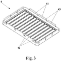
Fig. 3 shows a perspective view of a header used in the heat exchanger assembly of the present invention, prior to bending; -
Fig. 4 shows a cross-section view of the header prior to bending; -
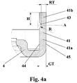
Fig. 4a shows a detail offig. 4 ; -
Fig. 5 shows a view similar to that offig. 4a , but illustrating an another embodiment of the present invention; -
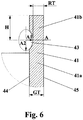
Fig. 6 shows an another example of an undercut prior to bending; and -
Fig. 7 shows and enlarged detailed view of an another example of the undercut. - A heat exchanger assembly according to the present invention is indicated as a whole by
numeral reference 1. Theheat exchanger assembly 1 comprises ahousing 2, which in the embodiment shown in the figures is made of two separate half-shells, i.e. a first half-shell 21 and a second half-shell 22. Of course, thehousing 2 can consist of any appropriate number of shells and/or plates, e.g. three, four, etc. Thehousing 2 includes inlet andoutlet ports degassing port 25, which serves to remove the air that may be trapped in the coolant. - A core 3 is placed tightly inside the
housing 2. The core 3 includes a plurality of spaced-apart flathollow flow tubes 31, i.e. there is some free space between twoadjacent flow tubes 31 and the coolant flows through these free spaces. In a preferred embodiment of the invention, shown in the figures, especially infigures 1 and2 , the core 3 further includes a plurality ofcoolant turbulators 32 arranged between theflow tubes 31. Namely, onecoolant turbulator 32 is situated between twoadjacent flow tubes 31. Thecoolant turbulators 32 function to turn a laminar flow of the coolant into a turbulent one and, in turn, to increase the heat exchange efficiency. Of course, in another embodiments of the invention, thecoolant turbulators 32 can be omitted. - The
flow tubes 31 are hollow and a medium to be cooled down, for example a fluid, such as a gas, flows therethrough. Theflow tubes 31 have two wide sides, two narrow sides and two open ends. Theflow tubes 31 are arranged with their wide sides parallel to each other. Theflow tubes 31 can be provided internally with a series of fluid fins. - The
heat exchanger assembly 1 further comprises twoheaders 4. Eachheader 4 is located on and connected to one end of the core 3, i.e. that presenting the open ends of theflow tubes 31. Moreover, each of theheaders 4 is, preferably at its entire outer perimeter, see in particularfig. 2 , in contact with an inner wall of thehousing 2. Theheader 4 comprises a plurality of throughslots 42 so that the open ends of theflow tubes 31 fit into theslots 42. The number of thethrough slots 42 is equal to the number of theflow tubes 31 and the shape of theslots 42 corresponds to the shape of the cross-section of the open ends of theflow tubes 31. - Moreover, the
heat exchanger assembly 1 comprises inlet andoutlet conduits inlet conduit 51 receives a hot medium from a motor vehicle and transfers it to the core 3 where it can be cooled down, whereas theoutlet conduit 52 delivers a medium of a lower temperature back to the motor vehicle. The inlet and outlet conduits 51, 52 cover theheaders 4 and close thehousing 2. In other words, the inlet and outlet conduits 51, 52 close two openings in thehousing 2, which are intended for the flow of the medium to be cooled down, and make thehousing 2 complete. Aseal 6 may be placed between each of theheaders 4 and each of the inlet andoutlet conduits - All components of the
heat exchanger assembly 1, except for theseal 6, can be made of materials suitable for brazing, for example aluminum, steel and their alloys. In order to obtain the proper fluid-tightness of the assembly all components thereof are connected to each other by brazing. - The
headers 4 comprise at their perimeters a plurality ofteeth 41. As seen infigure 2 , when theheat exchanger assembly 1 is assembled, the inlet andoutlet conduits headers 4. Moreover, theteeth 41 of theheaders 4 are bent over protruding portions of the inlet andoutlet conduits outlet conduits teeth 41 of theheaders 4. Theteeth 41 and theheaders 4 include aninner surface 44 and anouter surface 45. Additionally, theteeth 41 are provided on theirinner surfaces 44 withundercuts 43. The function of theundercuts 43 is to facilitate bending of theteeth 41 over the inlet andoutlet conduits outlet conduits teeth 41 of theheaders 4 and theteeth 41 are subsequently bent over the inlet andoutlet conduits figure 2 . - Reference is now made, particularly, to
fig. 4a , which shows in more detail the structure of theteeth 41 before they are bent over the inlet andoutlet conduits undercuts 43 has an undercut axis A. The undercut axis A extend through the deepest point of the undercut 43 and, if theteeth 41 are straight, is perpendicular to theinner surface 44 of thetooth 41. Moreover, in case of theundercuts 43 with a circular or elliptic cross-section, the undercut axis A divides the undercut 43 into two identical halves. The undercuts 43, more precisely their undercut axes A, divide eachtooth 41 into abase portion 41a and abendable portion 41b. When theteeth 41 are straight their undercut axes A are perpendicular to thebase portion 41a and thebendable portion 41b. Thebendable portion 41b has a height H measured from the undercut axis A to an end of thetooth 41. - In this embodiment, the
headers 4 and theteeth 41 have a general thickness GT. The general thickness GT of theheader 4 and/orteeth 41 should be understood as a thickness of a material used forheaders 4 andteeth 41 because both theheaders 4 and theteeth 41 are preferably made of a single sheet of material having a uniform thickness. Of course, if necessary, theheaders 4 and theteeth 41 can be made of a material with a varying thickness. Moreover, theteeth 41 have at their undercuts 43 a reduced thickness RT. Namely, the reduced thickness RT corresponds to the amount of header/tooth material left once theundercuts 43 have been made and prior to bending. The reduced thickness RT can also be defined as a distance between the deepest point of the undercut 43 and the nearest point on theouter surface 45 of thetooth 41. - In a preferred embodiment of the present invention, the general thickness GT of the
header 4 and, especially, theteeth 41 is 2mm. In such case, prior to bending, each undercut 41 has a circular cross-section and has a radius R of 1mm, while the reduced thickness RT is 1,5 mm and the height H is 3mm. This in turn means that the undercut 43 has a surface, which is in fact a sector of a cylindrical surface. The position of the undercut 43 on theinner surface 44 of thetooth 41 is such that the undercut axis A, when the inlet andoutlet conduits teeth 41 prior to bending, is located above a surface over which theteeth 41 are to be bent, in this case asurface 51a of the inlet andoutlet conduits teeth 41 have been bent over the protruding portions of the inlet andoutlet conduits surface 51a, sharp edges inside theundercuts 43 of the alreadybent teeth 41 are avoided. In particular, following bending, in theundercuts 43 there always remains a smooth surface with a radius, what in turn means that stresses caused by bending do not concentrate critically in theundercuts 43, as it is the case with solutions known from the prior art. - It is also important to note that the
undercuts 43 should be originally free from any sharp edges, i.e. they should include only smooth surfaces. - Of course, the present invention is not limited to the dimensions mentioned above, which represent only one embodiment of the
heat exchanger assembly 1. In more general terms, it is important to note that, before bending theteeth 41 over the inlet andoutlet conduits bendable portion 41b of thetooth 41, while the radius R of the undercut 43 should be at least half of the general thickness GT of the material used for theheaders 4 and, especially, theteeth 41. - Additionally, the
undercuts 43 may have other shapes of cross-section than those shown infigures 1-5 and described above. In an another embodiment of the invention, theundercuts 43 may have an elliptic cross-section before bending theteeth 41 over the inlet andoutlet conduits figure 6 , a semi-minor axis A1 of an ellipse of the undercut cross section coincides with the undercut axis A, whereas a semi-major axis A2 of the ellipse of the undercut 43 is perpendicular to the undercut axis A. Similarly to the embodiment with the circular cross-section of theundercuts 43, especially as regards the radius R of the undercut 43, the semi-minor axis A1 of the ellipse has a length, which is at least half of the general thickness GT of the material used for theheaders 4 and, especially, theteeth 41. Preferably, the semi-minor axis A1 is 1 mm long and the general thickness GT is 2mm. The length of the semi-major axis A2 is in general greater than the length of the semi-minor axis A1. However, in a particular case, the semi-major axis A2 and the semi-minor axis A1 of the undercut 43 can be of equal lengths. It means that theundercuts 43 have once again the circular cross-section, as discussed above. In other words a circle is the special case of an ellipse, and the semi-minor axis A1 and the semi-major axis A2 of the ellipse simply become the radius R of the circle, which is constant throughout the undercut 43. - As shown in
figure 3 , theundercuts 43 extend through the entire width of theteeth 41, i.e. they open to edges of theteeth 41. However, in another embodiments of the present invention theundercuts 43 can be interrupted in a distance from the edges of the teeth 41 (Figure 7 ), i.e. theundercuts 43 end before reaching the edges. - In yet another embodiment of the present invention, to allow for easier introduction of the inlet and
outlet conduits teeth 41 of theheaders 4, before assembling theheat exchanger assembly 1, thebendable portions 41b of theteeth 41 are slightly pre-bent at theundercuts 43 towards the outside of theheaders 4. Preferably, an angle of the pre-bend is 20° with respect to the extension of thebase portion 41a. As theteeth 41 are pre-bent at theirundercuts 43, the undercut axes A are no longer perpendicular to thebase portion 41a of eachtooth 41 but are slightly rotated, depending on the angle at which thebendable portion 41b is pre-bent. Of course, all relevant relationships between the reduced thickness RT, the general thickness GT, the height H and the radius R, as well as the semi-minor axis A1 and the semi-major axis A2, defined for the embodiments described above, apply to this embodiment as well. One must only take into account the pre-bend of theteeth 41 as well as the resultant rotation of the undercut axes A. - Of course, the present invention is not limited to the literal meaning of the features described above and presented in the claims but also includes other equivalent features, which are obvious for a skilled person.
Claims (7)
- A heat exchanger assembly (1) comprising:a housing (2);a core (3) situated inside said housing (2);two headers (4) placed on said core (3); andinlet and outlet conduits (51, 52) covering said headers (4) and closing said housing (2);wherein said headers (4) comprise at their perimeters a plurality of teeth (41), which are bent over said inlet and outlet conduits (51, 52);wherein each of said teeth (41) is provided on its inner surface (44) with an undercut (43) having an undercut axis (A); said undercut axis (A) dividing each of said teeth (41) into a base portion (41a) anda bendable portion (41b), said bendable portion (41b) having a height (H) measured from said undercut axis (A) to an end of each of said teeth (41);wherein each of said teeth (41) has a general thickness (GT) as well as a reduced thickness (RT) at said undercut (43); andwherein prior to bending of said teeth (41) over said inlet and outlet conduits (51, 52) said undercut (43) has a substantially elliptic cross-section and a semi-minor axis (A1) of an ellipse of said undercut cross-section coincides with said undercut axis (A);characterized in that
said semi-minor axis (A1) has a length, which is at least half of said general thickness (GT); and said reduced thickness (RT) of each of said teeth (41) is at most two times smaller than said height (H) of said bendable portion (41b). - The heat exchanger assembly (1) according to claim 1, characterized in that said length of said semi-minor axis (A1) is equal to a length of a semi-major axis (A2), whereby said undercuts (43) have in fact a circular cross-section so that said undercuts (43) have only one constant radius (R).
- The heat exchanger assembly (1) according to any one of the preceding claims, characterized in that said semi-minor axis (A1) and/or said radius (R) is/are 1mm long, said general thickness (GT) is 2mm, said reduced thickness (RT) is 1,5 mm and said height (H) is 3 mm.
- The heat exchanger assembly (1) according to any one of the preceding claims, characterized in that said undercuts (43) are positioned on said teeth (41) so that said undercut axes (A), prior to bending of said teeth (41) over said inlet and outlet conduits (51, 52), are situated above a surface (51a) over which said teeth (41) are to be bent.
- The heat exchanger assembly (1) according to any one of the preceding claims, characterized in that said undercuts (43) end in a distance from edges of said teeth (41).
- The heat exchanger assembly (1) according to any one of claims 1 to 4, characterized in that said undercuts (43) extend through an entire width of each of said teeth (41).
- The heat exchanger assembly (1) according to any one of the preceding claims, characterized in that said heat exchanger assembly (1) is a water charge air cooler.
Priority Applications (1)
| Application Number | Priority Date | Filing Date | Title |
|---|---|---|---|
| EP17461529.4A EP3396296B1 (en) | 2017-04-28 | 2017-04-28 | Heat exchanger assembly |
Applications Claiming Priority (1)
| Application Number | Priority Date | Filing Date | Title |
|---|---|---|---|
| EP17461529.4A EP3396296B1 (en) | 2017-04-28 | 2017-04-28 | Heat exchanger assembly |
Publications (2)
| Publication Number | Publication Date |
|---|---|
| EP3396296A1 true EP3396296A1 (en) | 2018-10-31 |
| EP3396296B1 EP3396296B1 (en) | 2020-09-09 |
Family
ID=58644991
Family Applications (1)
| Application Number | Title | Priority Date | Filing Date |
|---|---|---|---|
| EP17461529.4A Active EP3396296B1 (en) | 2017-04-28 | 2017-04-28 | Heat exchanger assembly |
Country Status (1)
| Country | Link |
|---|---|
| EP (1) | EP3396296B1 (en) |
Cited By (3)
| Publication number | Priority date | Publication date | Assignee | Title |
|---|---|---|---|---|
| US20220325964A1 (en) * | 2019-09-09 | 2022-10-13 | Valeo Autosystemy Sp. Z O.O. | A header-tank assembly |
| EP3722724B1 (en) * | 2019-04-12 | 2022-10-19 | João de Deus & Filhos, S.A. | Fluid-tight joint for heat exchanger and heat exchanger comprising such a joint. |
| JP2024024412A (en) * | 2022-08-09 | 2024-02-22 | 日野自動車株式会社 | Heat exchanger |
Citations (3)
| Publication number | Priority date | Publication date | Assignee | Title |
|---|---|---|---|---|
| WO1982003574A1 (en) * | 1981-04-13 | 1982-10-28 | Stroemberg Jan | Method of effecting bending |
| FR2968753A1 (en) * | 2010-12-10 | 2012-06-15 | Valeo Systemes Thermiques | Heat exchanger for exchanging heat between two fluids e.g. air and water, in diesel engine, of car, has stop device formed over entire periphery of contour, where stop device forms abutment of plates according to fluid flow axis |
| US20130333867A1 (en) * | 2010-12-07 | 2013-12-19 | Valeo Systemes Thermiques | Assembly Of Two Parts Crimped One Over The Other |
-
2017
- 2017-04-28 EP EP17461529.4A patent/EP3396296B1/en active Active
Patent Citations (3)
| Publication number | Priority date | Publication date | Assignee | Title |
|---|---|---|---|---|
| WO1982003574A1 (en) * | 1981-04-13 | 1982-10-28 | Stroemberg Jan | Method of effecting bending |
| US20130333867A1 (en) * | 2010-12-07 | 2013-12-19 | Valeo Systemes Thermiques | Assembly Of Two Parts Crimped One Over The Other |
| FR2968753A1 (en) * | 2010-12-10 | 2012-06-15 | Valeo Systemes Thermiques | Heat exchanger for exchanging heat between two fluids e.g. air and water, in diesel engine, of car, has stop device formed over entire periphery of contour, where stop device forms abutment of plates according to fluid flow axis |
Cited By (3)
| Publication number | Priority date | Publication date | Assignee | Title |
|---|---|---|---|---|
| EP3722724B1 (en) * | 2019-04-12 | 2022-10-19 | João de Deus & Filhos, S.A. | Fluid-tight joint for heat exchanger and heat exchanger comprising such a joint. |
| US20220325964A1 (en) * | 2019-09-09 | 2022-10-13 | Valeo Autosystemy Sp. Z O.O. | A header-tank assembly |
| JP2024024412A (en) * | 2022-08-09 | 2024-02-22 | 日野自動車株式会社 | Heat exchanger |
Also Published As
| Publication number | Publication date |
|---|---|
| EP3396296B1 (en) | 2020-09-09 |
Similar Documents
| Publication | Publication Date | Title |
|---|---|---|
| CN108463682B (en) | U-shaped tube heat exchanger | |
| ES2764838T3 (en) | Heat exchanger that has a fin plate to reduce an EGR gas pressure difference | |
| US10866030B2 (en) | Heat exchanger | |
| CN100489431C (en) | Heat exchanger | |
| US6032728A (en) | Variable pitch heat exchanger | |
| US20150300745A1 (en) | Counterflow helical heat exchanger | |
| EP3561426B1 (en) | Heat exchange device | |
| EP3396296B1 (en) | Heat exchanger assembly | |
| EP1795854A1 (en) | Heat exchanger | |
| EP2469215A1 (en) | Tube heat exchanger | |
| EP2977697A2 (en) | Heat exchanger and heat exchanging unit | |
| EP2265882B1 (en) | Header plate and heat exchanger comprising same | |
| CN104735988A (en) | Hot air oven | |
| RU2358218C1 (en) | Spiral-type heat exchanger and its fabrication method | |
| JP5213941B2 (en) | Heat exchanger | |
| CN111512109B (en) | Header-plate-free heat exchanger | |
| EP3652492B1 (en) | Heat exchanger comprising fluid tubes having a first and a second inner wall | |
| CN109696070B (en) | Heat exchanger | |
| US20100294474A1 (en) | Heat exchanger tube | |
| RU74697U1 (en) | SPIRAL HEAT EXCHANGER | |
| US11112191B2 (en) | Heat exchanger with turbulating inserts | |
| US10663236B2 (en) | Tube heat exchanger and method of manufacturing such a heat exchanger | |
| EP3236188A1 (en) | Heat exchangers | |
| WO2019174734A1 (en) | Heat exchanger assembly | |
| EP3376147B1 (en) | Heat exchanger assembly |
Legal Events
| Date | Code | Title | Description |
|---|---|---|---|
| PUAI | Public reference made under article 153(3) epc to a published international application that has entered the european phase |
Free format text: ORIGINAL CODE: 0009012 |
|
| STAA | Information on the status of an ep patent application or granted ep patent |
Free format text: STATUS: THE APPLICATION HAS BEEN PUBLISHED |
|
| AK | Designated contracting states |
Kind code of ref document: A1 Designated state(s): AL AT BE BG CH CY CZ DE DK EE ES FI FR GB GR HR HU IE IS IT LI LT LU LV MC MK MT NL NO PL PT RO RS SE SI SK SM TR |
|
| AX | Request for extension of the european patent |
Extension state: BA ME |
|
| STAA | Information on the status of an ep patent application or granted ep patent |
Free format text: STATUS: REQUEST FOR EXAMINATION WAS MADE |
|
| 17P | Request for examination filed |
Effective date: 20190415 |
|
| RBV | Designated contracting states (corrected) |
Designated state(s): AL AT BE BG CH CY CZ DE DK EE ES FI FR GB GR HR HU IE IS IT LI LT LU LV MC MK MT NL NO PL PT RO RS SE SI SK SM TR |
|
| STAA | Information on the status of an ep patent application or granted ep patent |
Free format text: STATUS: EXAMINATION IS IN PROGRESS |
|
| 17Q | First examination report despatched |
Effective date: 20190816 |
|
| GRAP | Despatch of communication of intention to grant a patent |
Free format text: ORIGINAL CODE: EPIDOSNIGR1 |
|
| STAA | Information on the status of an ep patent application or granted ep patent |
Free format text: STATUS: GRANT OF PATENT IS INTENDED |
|
| INTG | Intention to grant announced |
Effective date: 20200330 |
|
| GRAS | Grant fee paid |
Free format text: ORIGINAL CODE: EPIDOSNIGR3 |
|
| GRAA | (expected) grant |
Free format text: ORIGINAL CODE: 0009210 |
|
| STAA | Information on the status of an ep patent application or granted ep patent |
Free format text: STATUS: THE PATENT HAS BEEN GRANTED |
|
| AK | Designated contracting states |
Kind code of ref document: B1 Designated state(s): AL AT BE BG CH CY CZ DE DK EE ES FI FR GB GR HR HU IE IS IT LI LT LU LV MC MK MT NL NO PL PT RO RS SE SI SK SM TR |
|
| REG | Reference to a national code |
Ref country code: GB Ref legal event code: FG4D |
|
| REG | Reference to a national code |
Ref country code: AT Ref legal event code: REF Ref document number: 1312105 Country of ref document: AT Kind code of ref document: T Effective date: 20200915 Ref country code: CH Ref legal event code: EP |
|
| REG | Reference to a national code |
Ref country code: IE Ref legal event code: FG4D |
|
| REG | Reference to a national code |
Ref country code: DE Ref legal event code: R096 Ref document number: 602017023239 Country of ref document: DE |
|
| REG | Reference to a national code |
Ref country code: LT Ref legal event code: MG4D |
|
| PG25 | Lapsed in a contracting state [announced via postgrant information from national office to epo] |
Ref country code: GR Free format text: LAPSE BECAUSE OF FAILURE TO SUBMIT A TRANSLATION OF THE DESCRIPTION OR TO PAY THE FEE WITHIN THE PRESCRIBED TIME-LIMIT Effective date: 20201210 Ref country code: LT Free format text: LAPSE BECAUSE OF FAILURE TO SUBMIT A TRANSLATION OF THE DESCRIPTION OR TO PAY THE FEE WITHIN THE PRESCRIBED TIME-LIMIT Effective date: 20200909 Ref country code: FI Free format text: LAPSE BECAUSE OF FAILURE TO SUBMIT A TRANSLATION OF THE DESCRIPTION OR TO PAY THE FEE WITHIN THE PRESCRIBED TIME-LIMIT Effective date: 20200909 Ref country code: NO Free format text: LAPSE BECAUSE OF FAILURE TO SUBMIT A TRANSLATION OF THE DESCRIPTION OR TO PAY THE FEE WITHIN THE PRESCRIBED TIME-LIMIT Effective date: 20201209 Ref country code: BG Free format text: LAPSE BECAUSE OF FAILURE TO SUBMIT A TRANSLATION OF THE DESCRIPTION OR TO PAY THE FEE WITHIN THE PRESCRIBED TIME-LIMIT Effective date: 20201209 Ref country code: SE Free format text: LAPSE BECAUSE OF FAILURE TO SUBMIT A TRANSLATION OF THE DESCRIPTION OR TO PAY THE FEE WITHIN THE PRESCRIBED TIME-LIMIT Effective date: 20200909 Ref country code: HR Free format text: LAPSE BECAUSE OF FAILURE TO SUBMIT A TRANSLATION OF THE DESCRIPTION OR TO PAY THE FEE WITHIN THE PRESCRIBED TIME-LIMIT Effective date: 20200909 |
|
| REG | Reference to a national code |
Ref country code: AT Ref legal event code: MK05 Ref document number: 1312105 Country of ref document: AT Kind code of ref document: T Effective date: 20200909 |
|
| REG | Reference to a national code |
Ref country code: NL Ref legal event code: MP Effective date: 20200909 |
|
| PG25 | Lapsed in a contracting state [announced via postgrant information from national office to epo] |
Ref country code: PL Free format text: LAPSE BECAUSE OF FAILURE TO SUBMIT A TRANSLATION OF THE DESCRIPTION OR TO PAY THE FEE WITHIN THE PRESCRIBED TIME-LIMIT Effective date: 20200909 Ref country code: RS Free format text: LAPSE BECAUSE OF FAILURE TO SUBMIT A TRANSLATION OF THE DESCRIPTION OR TO PAY THE FEE WITHIN THE PRESCRIBED TIME-LIMIT Effective date: 20200909 Ref country code: LV Free format text: LAPSE BECAUSE OF FAILURE TO SUBMIT A TRANSLATION OF THE DESCRIPTION OR TO PAY THE FEE WITHIN THE PRESCRIBED TIME-LIMIT Effective date: 20200909 |
|
| PG25 | Lapsed in a contracting state [announced via postgrant information from national office to epo] |
Ref country code: EE Free format text: LAPSE BECAUSE OF FAILURE TO SUBMIT A TRANSLATION OF THE DESCRIPTION OR TO PAY THE FEE WITHIN THE PRESCRIBED TIME-LIMIT Effective date: 20200909 Ref country code: SM Free format text: LAPSE BECAUSE OF FAILURE TO SUBMIT A TRANSLATION OF THE DESCRIPTION OR TO PAY THE FEE WITHIN THE PRESCRIBED TIME-LIMIT Effective date: 20200909 Ref country code: PT Free format text: LAPSE BECAUSE OF FAILURE TO SUBMIT A TRANSLATION OF THE DESCRIPTION OR TO PAY THE FEE WITHIN THE PRESCRIBED TIME-LIMIT Effective date: 20210111 Ref country code: RO Free format text: LAPSE BECAUSE OF FAILURE TO SUBMIT A TRANSLATION OF THE DESCRIPTION OR TO PAY THE FEE WITHIN THE PRESCRIBED TIME-LIMIT Effective date: 20200909 Ref country code: CZ Free format text: LAPSE BECAUSE OF FAILURE TO SUBMIT A TRANSLATION OF THE DESCRIPTION OR TO PAY THE FEE WITHIN THE PRESCRIBED TIME-LIMIT Effective date: 20200909 |
|
| PG25 | Lapsed in a contracting state [announced via postgrant information from national office to epo] |
Ref country code: IS Free format text: LAPSE BECAUSE OF FAILURE TO SUBMIT A TRANSLATION OF THE DESCRIPTION OR TO PAY THE FEE WITHIN THE PRESCRIBED TIME-LIMIT Effective date: 20210109 Ref country code: AL Free format text: LAPSE BECAUSE OF FAILURE TO SUBMIT A TRANSLATION OF THE DESCRIPTION OR TO PAY THE FEE WITHIN THE PRESCRIBED TIME-LIMIT Effective date: 20200909 Ref country code: AT Free format text: LAPSE BECAUSE OF FAILURE TO SUBMIT A TRANSLATION OF THE DESCRIPTION OR TO PAY THE FEE WITHIN THE PRESCRIBED TIME-LIMIT Effective date: 20200909 Ref country code: ES Free format text: LAPSE BECAUSE OF FAILURE TO SUBMIT A TRANSLATION OF THE DESCRIPTION OR TO PAY THE FEE WITHIN THE PRESCRIBED TIME-LIMIT Effective date: 20200909 |
|
| REG | Reference to a national code |
Ref country code: DE Ref legal event code: R097 Ref document number: 602017023239 Country of ref document: DE |
|
| PG25 | Lapsed in a contracting state [announced via postgrant information from national office to epo] |
Ref country code: SK Free format text: LAPSE BECAUSE OF FAILURE TO SUBMIT A TRANSLATION OF THE DESCRIPTION OR TO PAY THE FEE WITHIN THE PRESCRIBED TIME-LIMIT Effective date: 20200909 |
|
| PLBE | No opposition filed within time limit |
Free format text: ORIGINAL CODE: 0009261 |
|
| STAA | Information on the status of an ep patent application or granted ep patent |
Free format text: STATUS: NO OPPOSITION FILED WITHIN TIME LIMIT |
|
| 26N | No opposition filed |
Effective date: 20210610 |
|
| PG25 | Lapsed in a contracting state [announced via postgrant information from national office to epo] |
Ref country code: DK Free format text: LAPSE BECAUSE OF FAILURE TO SUBMIT A TRANSLATION OF THE DESCRIPTION OR TO PAY THE FEE WITHIN THE PRESCRIBED TIME-LIMIT Effective date: 20200909 Ref country code: SI Free format text: LAPSE BECAUSE OF FAILURE TO SUBMIT A TRANSLATION OF THE DESCRIPTION OR TO PAY THE FEE WITHIN THE PRESCRIBED TIME-LIMIT Effective date: 20200909 |
|
| PG25 | Lapsed in a contracting state [announced via postgrant information from national office to epo] |
Ref country code: IT Free format text: LAPSE BECAUSE OF FAILURE TO SUBMIT A TRANSLATION OF THE DESCRIPTION OR TO PAY THE FEE WITHIN THE PRESCRIBED TIME-LIMIT Effective date: 20200909 |
|
| PG25 | Lapsed in a contracting state [announced via postgrant information from national office to epo] |
Ref country code: MC Free format text: LAPSE BECAUSE OF FAILURE TO SUBMIT A TRANSLATION OF THE DESCRIPTION OR TO PAY THE FEE WITHIN THE PRESCRIBED TIME-LIMIT Effective date: 20200909 |
|
| GBPC | Gb: european patent ceased through non-payment of renewal fee |
Effective date: 20210428 |
|
| PG25 | Lapsed in a contracting state [announced via postgrant information from national office to epo] |
Ref country code: LU Free format text: LAPSE BECAUSE OF NON-PAYMENT OF DUE FEES Effective date: 20210428 |
|
| REG | Reference to a national code |
Ref country code: BE Ref legal event code: MM Effective date: 20210430 |
|
| PG25 | Lapsed in a contracting state [announced via postgrant information from national office to epo] |
Ref country code: LI Free format text: LAPSE BECAUSE OF NON-PAYMENT OF DUE FEES Effective date: 20210430 Ref country code: CH Free format text: LAPSE BECAUSE OF NON-PAYMENT OF DUE FEES Effective date: 20210430 Ref country code: GB Free format text: LAPSE BECAUSE OF NON-PAYMENT OF DUE FEES Effective date: 20210428 |
|
| PG25 | Lapsed in a contracting state [announced via postgrant information from national office to epo] |
Ref country code: IE Free format text: LAPSE BECAUSE OF NON-PAYMENT OF DUE FEES Effective date: 20210428 |
|
| PG25 | Lapsed in a contracting state [announced via postgrant information from national office to epo] |
Ref country code: IS Free format text: LAPSE BECAUSE OF FAILURE TO SUBMIT A TRANSLATION OF THE DESCRIPTION OR TO PAY THE FEE WITHIN THE PRESCRIBED TIME-LIMIT Effective date: 20210109 |
|
| PG25 | Lapsed in a contracting state [announced via postgrant information from national office to epo] |
Ref country code: BE Free format text: LAPSE BECAUSE OF NON-PAYMENT OF DUE FEES Effective date: 20210430 |
|
| PG25 | Lapsed in a contracting state [announced via postgrant information from national office to epo] |
Ref country code: NL Free format text: LAPSE BECAUSE OF NON-PAYMENT OF DUE FEES Effective date: 20200923 Ref country code: CY Free format text: LAPSE BECAUSE OF FAILURE TO SUBMIT A TRANSLATION OF THE DESCRIPTION OR TO PAY THE FEE WITHIN THE PRESCRIBED TIME-LIMIT Effective date: 20200909 |
|
| P01 | Opt-out of the competence of the unified patent court (upc) registered |
Effective date: 20230528 |
|
| PG25 | Lapsed in a contracting state [announced via postgrant information from national office to epo] |
Ref country code: HU Free format text: LAPSE BECAUSE OF FAILURE TO SUBMIT A TRANSLATION OF THE DESCRIPTION OR TO PAY THE FEE WITHIN THE PRESCRIBED TIME-LIMIT; INVALID AB INITIO Effective date: 20170428 |
|
| PG25 | Lapsed in a contracting state [announced via postgrant information from national office to epo] |
Ref country code: MK Free format text: LAPSE BECAUSE OF FAILURE TO SUBMIT A TRANSLATION OF THE DESCRIPTION OR TO PAY THE FEE WITHIN THE PRESCRIBED TIME-LIMIT Effective date: 20200909 |
|
| PG25 | Lapsed in a contracting state [announced via postgrant information from national office to epo] |
Ref country code: TR Free format text: LAPSE BECAUSE OF FAILURE TO SUBMIT A TRANSLATION OF THE DESCRIPTION OR TO PAY THE FEE WITHIN THE PRESCRIBED TIME-LIMIT Effective date: 20200909 |
|
| PG25 | Lapsed in a contracting state [announced via postgrant information from national office to epo] |
Ref country code: MT Free format text: LAPSE BECAUSE OF FAILURE TO SUBMIT A TRANSLATION OF THE DESCRIPTION OR TO PAY THE FEE WITHIN THE PRESCRIBED TIME-LIMIT Effective date: 20200909 |
|
| PGFP | Annual fee paid to national office [announced via postgrant information from national office to epo] |
Ref country code: FR Payment date: 20250429 Year of fee payment: 9 |
|
| PGFP | Annual fee paid to national office [announced via postgrant information from national office to epo] |
Ref country code: DE Payment date: 20260416 Year of fee payment: 10 |