EP3396119A1 - Intershaft compartment buffering arrangement - Google Patents
Intershaft compartment buffering arrangement Download PDFInfo
- Publication number
- EP3396119A1 EP3396119A1 EP18158465.7A EP18158465A EP3396119A1 EP 3396119 A1 EP3396119 A1 EP 3396119A1 EP 18158465 A EP18158465 A EP 18158465A EP 3396119 A1 EP3396119 A1 EP 3396119A1
- Authority
- EP
- European Patent Office
- Prior art keywords
- air
- seal
- shaft
- oil seal
- oil
- Prior art date
- Legal status (The legal status is an assumption and is not a legal conclusion. Google has not performed a legal analysis and makes no representation as to the accuracy of the status listed.)
- Granted
Links
Images

Classifications
-
- F—MECHANICAL ENGINEERING; LIGHTING; HEATING; WEAPONS; BLASTING
- F01—MACHINES OR ENGINES IN GENERAL; ENGINE PLANTS IN GENERAL; STEAM ENGINES
- F01D—NON-POSITIVE DISPLACEMENT MACHINES OR ENGINES, e.g. STEAM TURBINES
- F01D5/00—Blades; Blade-carrying members; Heating, heat-insulating, cooling or antivibration means on the blades or the members
- F01D5/02—Blade-carrying members, e.g. rotors
- F01D5/026—Shaft to shaft connections
-
- F—MECHANICAL ENGINEERING; LIGHTING; HEATING; WEAPONS; BLASTING
- F01—MACHINES OR ENGINES IN GENERAL; ENGINE PLANTS IN GENERAL; STEAM ENGINES
- F01D—NON-POSITIVE DISPLACEMENT MACHINES OR ENGINES, e.g. STEAM TURBINES
- F01D11/00—Preventing or minimising internal leakage of working-fluid, e.g. between stages
- F01D11/003—Preventing or minimising internal leakage of working-fluid, e.g. between stages by packing rings; Mechanical seals
-
- F—MECHANICAL ENGINEERING; LIGHTING; HEATING; WEAPONS; BLASTING
- F01—MACHINES OR ENGINES IN GENERAL; ENGINE PLANTS IN GENERAL; STEAM ENGINES
- F01D—NON-POSITIVE DISPLACEMENT MACHINES OR ENGINES, e.g. STEAM TURBINES
- F01D25/00—Component parts, details, or accessories, not provided for in, or of interest apart from, other groups
- F01D25/16—Arrangement of bearings; Supporting or mounting bearings in casings
- F01D25/162—Bearing supports
-
- F—MECHANICAL ENGINEERING; LIGHTING; HEATING; WEAPONS; BLASTING
- F01—MACHINES OR ENGINES IN GENERAL; ENGINE PLANTS IN GENERAL; STEAM ENGINES
- F01D—NON-POSITIVE DISPLACEMENT MACHINES OR ENGINES, e.g. STEAM TURBINES
- F01D25/00—Component parts, details, or accessories, not provided for in, or of interest apart from, other groups
- F01D25/18—Lubricating arrangements
- F01D25/183—Sealing means
-
- F—MECHANICAL ENGINEERING; LIGHTING; HEATING; WEAPONS; BLASTING
- F04—POSITIVE - DISPLACEMENT MACHINES FOR LIQUIDS; PUMPS FOR LIQUIDS OR ELASTIC FLUIDS
- F04D—NON-POSITIVE-DISPLACEMENT PUMPS
- F04D27/00—Control, e.g. regulation, of pumps, pumping installations or pumping systems specially adapted for elastic fluids
- F04D27/009—Control, e.g. regulation, of pumps, pumping installations or pumping systems specially adapted for elastic fluids by bleeding, by passing or recycling fluid
-
- F—MECHANICAL ENGINEERING; LIGHTING; HEATING; WEAPONS; BLASTING
- F04—POSITIVE - DISPLACEMENT MACHINES FOR LIQUIDS; PUMPS FOR LIQUIDS OR ELASTIC FLUIDS
- F04D—NON-POSITIVE-DISPLACEMENT PUMPS
- F04D29/00—Details, component parts, or accessories
- F04D29/05—Shafts or bearings, or assemblies thereof, specially adapted for elastic fluid pumps
- F04D29/053—Shafts
- F04D29/054—Arrangements for joining or assembling shafts
-
- F—MECHANICAL ENGINEERING; LIGHTING; HEATING; WEAPONS; BLASTING
- F05—INDEXING SCHEMES RELATING TO ENGINES OR PUMPS IN VARIOUS SUBCLASSES OF CLASSES F01-F04
- F05D—INDEXING SCHEME FOR ASPECTS RELATING TO NON-POSITIVE-DISPLACEMENT MACHINES OR ENGINES, GAS-TURBINES OR JET-PROPULSION PLANTS
- F05D2220/00—Application
- F05D2220/30—Application in turbines
- F05D2220/32—Application in turbines in gas turbines
-
- F—MECHANICAL ENGINEERING; LIGHTING; HEATING; WEAPONS; BLASTING
- F05—INDEXING SCHEMES RELATING TO ENGINES OR PUMPS IN VARIOUS SUBCLASSES OF CLASSES F01-F04
- F05D—INDEXING SCHEME FOR ASPECTS RELATING TO NON-POSITIVE-DISPLACEMENT MACHINES OR ENGINES, GAS-TURBINES OR JET-PROPULSION PLANTS
- F05D2240/00—Components
- F05D2240/60—Shafts
Definitions
- Gas turbine engines such as those which power aircraft and industrial equipment, employ a compressor to compress air that is drawn into the engine and a turbine to capture energy associated with the combustion of a fuel-air mixture.
- FIG. 2 a prior art system 200 associated with an engine is shown.
- the system 200 is referenced with respect to a centerline/axis 202.
- the components of the system 200 that are described below are arranged relative to the axis 202 as shown in FIG. 2 .
- the system 200 is shown as part of a two-spool configuration that includes a first, low speed shaft 214 and a second, high speed shaft 220.
- the shafts 214 and 220 are rotatably supported by a plurality of bearings contained within a bearing compartment 224.
- FIG. 2 various locations of the engine are denoted by letters A-D. At each of these locations A-D, a pair of seals are shown. Seals are used in the system 200 to isolate a fluid from one or more areas/regions of the engine. Seals control various parameters (e.g., temperature, pressure) within the areas/regions of the engine and ensure proper/efficient engine operation and stability.
- An air seal 230a and an oil seal 234a are shown.
- an air seal 230b and an oil seal 234b are shown.
- Each of the oil seal comprises a radially interior side/surface and radially exterior side/surface.
- an air seal 230c and an oil seal 234c are shown.
- an air seal 230d and an oil seal 234d are shown.
- the seals 230a and 234a are used to seal the bearing compartment 224 with respect to the shaft 214.
- the seals 230d and 234d are used to seal the bearing compartment 224 with respect to the shaft 220.
- the seals 230b, 234b, 230c, and 234c are used to provide intershaft sealing between the shafts 214 and 220, in an area/region where the shafts 214 and 220 interact with or surround one another.
- a buffer source 228-1 provides air that interfaces to/between each of the pairs of seals (e.g., air seal and oil seal) at the respective locations A-D.
- the buffer source 228-1 originates from one or more stages of a low pressure compressor (LPC), such as for example an axially aft-most stage of the LPC.
- LPC low pressure compressor
- the air from the buffer source 228-1 may be at a greater pressure than the air pressure associated with a high pressure compressor (HPC) 228-2 of the compressor, such that air may flow from the buffer source 228-1, across the air seals 230b and 230c, and into the sink represented by the HPC 228-2.
- HPC high pressure compressor
- Typical, commercially available off the shelf (COTS) seals that may otherwise be used for the air seals 230b and 230c may not be configured to operate in such a manner, such that the air flowing across the air seals 230b and 230c as described above may degrade the service lifetime of such air seals 230b and 230c and/or render the air seals 230b and 230c inoperative, such that there may be an increased risk/potential of oil leaking out of the bearing compartment 224.
- COTS off the shelf
- the system may comprise a first shaft axially extending along the central longitudinal axis.
- the system may further comprise a second shaft coaxial with the first shaft.
- the system may also comprise a first air seal that seals between the first shaft and the second shaft at a first axial location.
- the system may comprise a second air seal that seals between the first shaft and the second shaft at a second axial location.
- the system may further comprise a first oil seal that provides intershaft sealing between the first shaft and the second shaft at a third axial location.
- the system may comprise a second oil seal that provides intershaft sealing between the first shaft and the second shaft at a fourth axial location axially adjacent to the third axial location.
- the system may further comprise a high pressure compressor that provides pressurized air to a first radially exterior side of the first air seal and to a second radially exterior side the second air seal.
- the first air seal and the second air seal may consume a portion of the air.
- the system may comprise a first oil seal that is substantially located at the first axial location.
- the system may further comprise a second oil seal that is substantially located at the second axial location.
- a gas turbine engine may comprise an inner shaft.
- the gas turbine engine may further comprise an outer shaft concentrically surrounding at least a portion of the inner shaft, wherein an interface between the outer shaft and the inner shaft is located within an annulus.
- the gas turbine engine may also comprise an oil seal positioned within the annulus and configured to prevent lubricating oil in the annulus from entering the interface.
- the gas turbine engine may comprise a high pressure compressor configured to provide pressurized air to a radially exterior side of the oil seal and configured to provide the pressurized air to a radially interior side of the oil seal.
- the outer shaft may comprise a high pressure compressor shaft and the inner shaft may comprise a low pressure turbine shaft.
- a gas turbine engine may comprise an intershaft seal separating a bearing compartment from an annulus and configured to prevent a lubricating oil in the bearing compartment from entering the annulus.
- the gas turbine engine may further comprise an outer shaft concentrically surrounding at least a portion of an inner shaft, where an interface between the outer shaft and the inner shaft is located within the annulus.
- the gas turbine engine may also comprise an oil seal positioned within the annulus and configured to prevent lubricating oil in the annulus from entering the interface.
- the gas turbine engine may comprise a high pressure compressor configured to provide pressurized air to a radially exterior side of the oil seal and configured to provide the pressurized air to a radially interior side of the oil seal.
- a system for a gas turbine engine may comprise a first shaft axially extending along an engine central longitudinal axis.
- the system may also comprise a second shaft coaxial with and radially exterior to the first shaft.
- the system may further comprise a first air seal and oil seal pair at an axial upstream position that seals a bearing compartment with respect to one of the first shaft and the second shaft and a second air seal and oil seal pair at an axial downstream position that seals the bearing compartment with respect to another of the first shaft and the second shaft.
- the system may comprise a plurality of intershaft seals radially between the first shaft and the second shaft and axially between the first air seal and oil seal pair and the second first air seal and oil seal pair, wherein each of the intershaft seals is an oil seal and wherein buffer air diverted from an engine compressor is delivered to at least a first intershaft space axially between at least a first pair of adjacent intershaft seals from the plurality of intershaft seals.
- connections are set forth between elements in the following description and in the drawings (the contents of which are incorporated in this specification by way of reference). It is noted that these connections are general and, unless specified otherwise, may be direct or indirect and that this specification is not intended to be limiting in this respect.
- a coupling between two or more entities may refer to a direct connection or an indirect connection.
- An indirect connection may incorporate one or more intervening entities or a space/gap between the entities that are being coupled to one another.
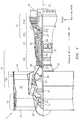
- FIG. 1 is a side cutaway illustration of a geared turbine engine 10.
- This turbine engine 10 extends along an axial centerline 12 between an upstream airflow inlet 14 and a downstream airflow exhaust 16.
- the turbine engine 10 includes a fan section 18, a compressor section 19, a combustor section 20 and a turbine section 21.
- the compressor section 19 includes a low pressure compressor (LPC) section 19A and a high pressure compressor (HPC) section 19B.
- the turbine section 21 includes a high pressure turbine (HPT) section 21A and a low pressure turbine (LPT) section 21B.
- the engine sections 18-21 are arranged sequentially along the centerline 12 within an engine housing 22.
- Each of the engine sections 18-19B, 21A and 21B includes a respective rotor 24-28.
- Each of these rotors 24-28 includes a plurality of rotor blades arranged circumferentially around and connected to one or more respective rotor disks.
- the rotor blades may be formed integral with or mechanically fastened, welded, brazed, adhered and/or otherwise attached to the respective rotor disk(s).
- the fan rotor 24 is connected to a gear train 30, for example, through a fan shaft 32.
- the gear train 30 and the LPC rotor 25 are connected to and driven by the LPT rotor 28 through a low speed shaft 33.
- the HPC rotor 26 is connected to and driven by the HPT rotor 27 through a high speed shaft 34.
- the shafts 32-34 are rotatably supported by a plurality of bearings 36; e.g., rolling element and/or thrust bearings. Each of these bearings 36 is connected to the engine housing 22 by at least one stationary structure such as, for example, an annular support strut.
- a fan drive gear system which may be incorporated as part of the gear train 30, may be used to separate the rotation of the fan rotor 24 from the rotation of the rotor 25 of the low pressure compressor section 19A and the rotor 28 of the low pressure turbine section 21B.
- FDGS fan drive gear system
- such an FDGS may allow the fan rotor 24 to rotate at a different (e.g., slower) speed relative to the rotors 25 and 28.
- the air within the core gas path 38 may be referred to as "core air”.
- the air within the bypass gas path 40 may be referred to as "bypass air”.
- the core air is directed through the engine sections 19-21, and exits the turbine engine 10 through the airflow exhaust 16 to provide forward engine thrust.
- fuel is injected into a combustion chamber 42 and mixed with compressed core air. This fuel-core air mixture is ignited to power the turbine engine 10.
- the bypass air is directed through the bypass gas path 40 and out of the turbine engine 10 through a bypass nozzle 44 to provide additional forward engine thrust. This additional forward engine thrust may account for a majority (e.g., more than 70 percent) of total engine thrust.
- at least some of the bypass air may be directed out of the turbine engine 10 through a thrust reverser to provide reverse engine thrust.
- FIG. 1 represents one possible configuration for an engine 10. Aspects of the disclosure may be applied in connection with other environments, including additional configurations for gas turbine engines. Aspects of the disclosure may be applied in connection with non-geared engines.
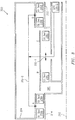
- FIG. 3 a simplified illustration of a vented buffer air supply system 300 for, e.g., intershaft seals is shown. Differences between the system 200 and the system 300 are described below.
- the system 300 may include an air seal 330a at the A location and an air seal 330d at the D location.
- the air seal 330a and the oil seal 234a may be used to seal the bearing compartment 224 with respect to the shaft 214.
- the air seal 330d and the oil seal 234d may be used to seal the bearing compartment 224 with respect to the shaft 220.
- the oil seal 234b and the oil seal 234c respectively, may be used to provide intershaft sealing between the shafts 214 and 220, in an area/region where the shafts 214 and 220 interact with or surround one another.
- Location A represents a location in front of #2 bearing.
- Location B represents a location behind #2 bearing on low speed shaft.
- Location C represents a location in front of #3 bearing on high speed shaft.
- Location D represents a location behind #3 bearing.
- the HPC 228-2 (which may correspond to the high pressure compressor (HPC) section 19B of FIG. 1 ) may be used as a source of air for buffering the seals.
- the system 300 may not utilize a buffer source (e.g., the buffer source 228-1 of FIG. 2 ) in relation to pressurizing the bearing compartment 224.
- a portion of the air from the HPC 228-2 (denoted by arrows 302-1) may be used/consumed with respect to the seals at the B and C locations.
- a portion of the air from the HPC 228-2 (denoted by arrows 302-2) may be used/consumed with respect to the seals at the A and D locations.
- HPC air for the intershaft compartment seals ensure they operate with the correct pressurization and it prevents backflow of HPC air into low pressure areas. Having generally equal pressure on the radially interior and exterior surface of the seals in the intershaft compartment reduces oil loss from the compartment in the event of a seal failure.
- HPC air as the buffer source allows the prior art air seals 230b, 230c ( FIG. 2 ) to be eliminated in the intershaft compartment buffering arrangement illustrated in FIG. 3 . This of course reduces weight and expense.
- FIG. 3 if an oil seal fails, pressure within the compartment will increase, but oil will be retained within the compartment 224 since the HPC air is feeding the source for all seals.
- the oil seals 234b, 234c are positioned in the annulus and configured to prevent lubricating oil in the annulus from entering the interface.
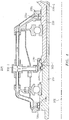
- FIG. 4 is a cross sectional illustration of an embodiment of the intershaft compartment buffering arrangement illustrated in FIG.3 , with the locations A, B, C and D identified therein.
Landscapes
- Engineering & Computer Science (AREA)
- Mechanical Engineering (AREA)
- General Engineering & Computer Science (AREA)
- Life Sciences & Earth Sciences (AREA)
- Sustainable Development (AREA)
- Turbine Rotor Nozzle Sealing (AREA)
- Sealing Devices (AREA)
- Sealing Using Fluids, Sealing Without Contact, And Removal Of Oil (AREA)
Abstract
Description
- Gas turbine engines, such as those which power aircraft and industrial equipment, employ a compressor to compress air that is drawn into the engine and a turbine to capture energy associated with the combustion of a fuel-air mixture. Referring to
FIG. 2 , aprior art system 200 associated with an engine is shown. Thesystem 200 is referenced with respect to a centerline/axis 202. For example, the components of thesystem 200 that are described below are arranged relative to theaxis 202 as shown inFIG. 2 . - The
system 200 is shown as part of a two-spool configuration that includes a first,low speed shaft 214 and a second,high speed shaft 220. Theshafts bearing compartment 224. - In
FIG. 2 , various locations of the engine are denoted by letters A-D. At each of these locations A-D, a pair of seals are shown. Seals are used in thesystem 200 to isolate a fluid from one or more areas/regions of the engine. Seals control various parameters (e.g., temperature, pressure) within the areas/regions of the engine and ensure proper/efficient engine operation and stability. At location A, anair seal 230a and anoil seal 234a are shown. At location B, anair seal 230b and anoil seal 234b are shown. Each of the oil seal comprises a radially interior side/surface and radially exterior side/surface. At location C, anair seal 230c and anoil seal 234c are shown. At location D, anair seal 230d and anoil seal 234d are shown. - The
seals bearing compartment 224 with respect to theshaft 214. Theseals bearing compartment 224 with respect to theshaft 220. Theseals shafts shafts - A buffer source 228-1 provides air that interfaces to/between each of the pairs of seals (e.g., air seal and oil seal) at the respective locations A-D. Conventionally, the buffer source 228-1 originates from one or more stages of a low pressure compressor (LPC), such as for example an axially aft-most stage of the LPC. In some instances, the air from the buffer source 228-1 may be at a greater pressure than the air pressure associated with a high pressure compressor (HPC) 228-2 of the compressor, such that air may flow from the buffer source 228-1, across the
air seals air seals air seals such air seals air seals bearing compartment 224. - The following presents a simplified summary in order to provide a basic understanding of some aspects of the disclosure. The summary is not an extensive overview of the disclosure. It is neither intended to identify key or critical elements of the disclosure nor to delineate the scope of the disclosure. The following summary merely presents some concepts of the disclosure in a simplified form as a prelude to the description below.
- Aspects of the disclosure are directed to a system associated with an engine having a central longitudinal axis. The system may comprise a first shaft axially extending along the central longitudinal axis. The system may further comprise a second shaft coaxial with the first shaft. The system may also comprise a first air seal that seals between the first shaft and the second shaft at a first axial location. The system may comprise a second air seal that seals between the first shaft and the second shaft at a second axial location. The system may further comprise a first oil seal that provides intershaft sealing between the first shaft and the second shaft at a third axial location. The system may comprise a second oil seal that provides intershaft sealing between the first shaft and the second shaft at a fourth axial location axially adjacent to the third axial location. The system may further comprise a high pressure compressor that provides pressurized air to a first radially exterior side of the first air seal and to a second radially exterior side the second air seal.
- The first air seal and the second air seal may consume a portion of the air.
- The system may comprise a first oil seal that is substantially located at the first axial location. The system may further comprise a second oil seal that is substantially located at the second axial location.
- According to another aspect of the present disclosure, a gas turbine engine is provided. The gas turbine engine may comprise an inner shaft. The gas turbine engine may further comprise an outer shaft concentrically surrounding at least a portion of the inner shaft, wherein an interface between the outer shaft and the inner shaft is located within an annulus. The gas turbine engine may also comprise an oil seal positioned within the annulus and configured to prevent lubricating oil in the annulus from entering the interface. The gas turbine engine may comprise a high pressure compressor configured to provide pressurized air to a radially exterior side of the oil seal and configured to provide the pressurized air to a radially interior side of the oil seal.
- The outer shaft may comprise a high pressure compressor shaft and the inner shaft may comprise a low pressure turbine shaft.
- According to another aspect of the present disclosure, a gas turbine engine is provided. The gas turbine engine may comprise an intershaft seal separating a bearing compartment from an annulus and configured to prevent a lubricating oil in the bearing compartment from entering the annulus. The gas turbine engine may further comprise an outer shaft concentrically surrounding at least a portion of an inner shaft, where an interface between the outer shaft and the inner shaft is located within the annulus. The gas turbine engine may also comprise an oil seal positioned within the annulus and configured to prevent lubricating oil in the annulus from entering the interface. The gas turbine engine may comprise a high pressure compressor configured to provide pressurized air to a radially exterior side of the oil seal and configured to provide the pressurized air to a radially interior side of the oil seal.
- According to another aspect of the present disclosure, a system for a gas turbine engine is provided. The system may comprise a first shaft axially extending along an engine central longitudinal axis. The system may also comprise a second shaft coaxial with and radially exterior to the first shaft. The system may further comprise a first air seal and oil seal pair at an axial upstream position that seals a bearing compartment with respect to one of the first shaft and the second shaft and a second air seal and oil seal pair at an axial downstream position that seals the bearing compartment with respect to another of the first shaft and the second shaft. The system may comprise a plurality of intershaft seals radially between the first shaft and the second shaft and axially between the first air seal and oil seal pair and the second first air seal and oil seal pair, wherein each of the intershaft seals is an oil seal and wherein buffer air diverted from an engine compressor is delivered to at least a first intershaft space axially between at least a first pair of adjacent intershaft seals from the plurality of intershaft seals.
- The present disclosure is illustrated by way of example and not limited in the accompanying figures in which like reference numerals indicate similar elements. The drawing figures are not necessarily drawn to scale unless specifically indicated otherwise.
-
FIG. 1 is a side cutaway illustration of a geared turbine engine. -
FIG. 2 illustrates a simplified illustration of a system of an engine that incorporates seals and a buffer air source in accordance with the prior art. -
FIG. 3 illustrates a simplified illustration of a system of an engine that incorporates seals and a buffer air source in accordance with aspects of this disclosure. -
FIG. 4 is a cross sectional illustration of an intershaft compartment buffering arrangement. - It is noted that various connections are set forth between elements in the following description and in the drawings (the contents of which are incorporated in this specification by way of reference). It is noted that these connections are general and, unless specified otherwise, may be direct or indirect and that this specification is not intended to be limiting in this respect. A coupling between two or more entities may refer to a direct connection or an indirect connection. An indirect connection may incorporate one or more intervening entities or a space/gap between the entities that are being coupled to one another.
- Aspects of the disclosure may be applied in connection with a gas turbine engine.
FIG. 1 is a side cutaway illustration of a gearedturbine engine 10. Thisturbine engine 10 extends along anaxial centerline 12 between anupstream airflow inlet 14 and adownstream airflow exhaust 16. Theturbine engine 10 includes afan section 18, acompressor section 19, acombustor section 20 and aturbine section 21. Thecompressor section 19 includes a low pressure compressor (LPC)section 19A and a high pressure compressor (HPC)section 19B. Theturbine section 21 includes a high pressure turbine (HPT)section 21A and a low pressure turbine (LPT)section 21B. - The engine sections 18-21 are arranged sequentially along the
centerline 12 within anengine housing 22. Each of the engine sections 18-19B, 21A and 21B includes a respective rotor 24-28. Each of these rotors 24-28 includes a plurality of rotor blades arranged circumferentially around and connected to one or more respective rotor disks. The rotor blades, for example, may be formed integral with or mechanically fastened, welded, brazed, adhered and/or otherwise attached to the respective rotor disk(s). - The
fan rotor 24 is connected to agear train 30, for example, through afan shaft 32. Thegear train 30 and theLPC rotor 25 are connected to and driven by theLPT rotor 28 through alow speed shaft 33. TheHPC rotor 26 is connected to and driven by theHPT rotor 27 through ahigh speed shaft 34. The shafts 32-34 are rotatably supported by a plurality ofbearings 36; e.g., rolling element and/or thrust bearings. Each of thesebearings 36 is connected to theengine housing 22 by at least one stationary structure such as, for example, an annular support strut. - As one skilled in the art would appreciate, in some embodiments a fan drive gear system (FDGS), which may be incorporated as part of the
gear train 30, may be used to separate the rotation of thefan rotor 24 from the rotation of therotor 25 of the lowpressure compressor section 19A and therotor 28 of the lowpressure turbine section 21B. For example, such an FDGS may allow thefan rotor 24 to rotate at a different (e.g., slower) speed relative to therotors - During operation, air enters the
turbine engine 10 through theairflow inlet 14, and is directed through thefan section 18 and into acore gas path 38 and abypass gas path 40. The air within thecore gas path 38 may be referred to as "core air". The air within thebypass gas path 40 may be referred to as "bypass air". The core air is directed through the engine sections 19-21, and exits theturbine engine 10 through theairflow exhaust 16 to provide forward engine thrust. Within thecombustor section 20, fuel is injected into acombustion chamber 42 and mixed with compressed core air. This fuel-core air mixture is ignited to power theturbine engine 10. The bypass air is directed through thebypass gas path 40 and out of theturbine engine 10 through abypass nozzle 44 to provide additional forward engine thrust. This additional forward engine thrust may account for a majority (e.g., more than 70 percent) of total engine thrust. Alternatively, at least some of the bypass air may be directed out of theturbine engine 10 through a thrust reverser to provide reverse engine thrust. -
FIG. 1 represents one possible configuration for anengine 10. Aspects of the disclosure may be applied in connection with other environments, including additional configurations for gas turbine engines. Aspects of the disclosure may be applied in connection with non-geared engines. - Referring to
FIG. 3 , a simplified illustration of a vented bufferair supply system 300 for, e.g., intershaft seals is shown. Differences between thesystem 200 and thesystem 300 are described below. - The
system 300 may include anair seal 330a at the A location and anair seal 330d at the D location. At the A location, theair seal 330a and theoil seal 234a may be used to seal thebearing compartment 224 with respect to theshaft 214. At the D location, theair seal 330d and theoil seal 234d may be used to seal thebearing compartment 224 with respect to theshaft 220. At the B and C locations, theoil seal 234b and theoil seal 234c, respectively, may be used to provide intershaft sealing between theshafts shafts - As shown in
FIG. 3 , the HPC 228-2 (which may correspond to the high pressure compressor (HPC)section 19B ofFIG. 1 ) may be used as a source of air for buffering the seals. Stated slightly differently, thesystem 300 may not utilize a buffer source (e.g., the buffer source 228-1 ofFIG. 2 ) in relation to pressurizing thebearing compartment 224. InFIG. 3 , a portion of the air from the HPC 228-2 (denoted by arrows 302-1) may be used/consumed with respect to the seals at the B and C locations. A portion of the air from the HPC 228-2 (denoted by arrows 302-2) may be used/consumed with respect to the seals at the A and D locations. - Using HPC air for the intershaft compartment seals ensure they operate with the correct pressurization and it prevents backflow of HPC air into low pressure areas. Having generally equal pressure on the radially interior and exterior surface of the seals in the intershaft compartment reduces oil loss from the compartment in the event of a seal failure. Using HPC air as the buffer source allows the prior art air seals 230b, 230c (
FIG. 2 ) to be eliminated in the intershaft compartment buffering arrangement illustrated inFIG. 3 . This of course reduces weight and expense. Referring still toFIG. 3 , if an oil seal fails, pressure within the compartment will increase, but oil will be retained within thecompartment 224 since the HPC air is feeding the source for all seals. The oil seals 234b, 234c are positioned in the annulus and configured to prevent lubricating oil in the annulus from entering the interface. -
FIG. 4 is a cross sectional illustration of an embodiment of the intershaft compartment buffering arrangement illustrated inFIG.3 , with the locations A, B, C and D identified therein. - Aspects of the disclosure have been described in terms of illustrative embodiments thereof. Numerous other embodiments, modifications, and variations within the scope of the appended claims will occur to persons of ordinary skill in the art from a review of this disclosure. For example, one of ordinary skill in the art will appreciate that the steps described in conjunction with the illustrative figures may be performed in other than the recited order, and that one or more steps illustrated may be optional in accordance with aspects of the disclosure. One or more features described in connection with a first embodiment may be combined with one or more features of one or more additional embodiments.
Claims (7)
- A system (300) for a gas turbine engine (10), comprising:an intershaft seal separating a bearing compartment (224) from an annulus and configured to prevent a lubricating oil in the bearing compartment (224) from entering the annulus;an outer shaft (220) concentrically surrounding at least a portion of an inner shaft (214), where an interface between the outer shaft (220) and the inner shaft (214) is located within the annulus;a first oil seal (234b, 234c) positioned within the annulus and configured to prevent lubricating oil in the annulus from entering the interface; anda high pressure compressor (228-2) configured to provide pressurized air (302-1, 302-2) to a radially exterior side of the oil seal (234b, 234c) and configured to provide the pressurized air (302-1, 302-2) to a radially interior side of the oil seal (234b, 234c).
- The system (300) of claim 1, further comprising:a first air seal and oil seal pair (330a, 234a), at an axial upstream position (A) with respect to the first oil seal (234b, 234c), that seals the bearing compartment (224) with respect to one of the inner shaft (214) and the outer shaft (220), and a second air seal and oil seal pair (330d, 234d), at an axial downstream position (D) with respect to the first oil seal (234b, 234c) that seals the bearing compartment (224) with respect to another of the inner shaft (214) and the outer shaft (220).
- The system of claim 2, where the pressurized air is delivered to radially exterior sides of both the first air seal and oil seal pair (330a, 234a) and the second air seal and oil seal pair (330d, 234d).
- The system of claim 2 or 3, where the pressurized air is delivered to a radially interior side of both the first air seal and oil seal pair (330a, 234a) and the second air seal and oil seal pair (330d, 234d).
- The system of claim 2, 3 or 4, further comprising a second oil seal (234c) positioned within the annulus and configured to prevent lubricating oil in the annulus from entering the interface.
- The system of claim 5, wherein, in use, the first oil seal (234b) and the second oil seal (234c) have equal air pressure on their radially interior and radially exterior surfaces to reduce oil loss if one of the first oil seal (234b) and the second oil seal fails (234c).
- A gas turbine engine comprising the system of any preceding claim.
Applications Claiming Priority (1)
| Application Number | Priority Date | Filing Date | Title |
|---|---|---|---|
| US15/496,399 US10513938B2 (en) | 2017-04-25 | 2017-04-25 | Intershaft compartment buffering arrangement |
Publications (2)
| Publication Number | Publication Date |
|---|---|
| EP3396119A1 true EP3396119A1 (en) | 2018-10-31 |
| EP3396119B1 EP3396119B1 (en) | 2021-09-29 |
Family
ID=61274209
Family Applications (1)
| Application Number | Title | Priority Date | Filing Date |
|---|---|---|---|
| EP18158465.7A Revoked EP3396119B1 (en) | 2017-04-25 | 2018-02-23 | Intershaft compartment buffering arrangement |
Country Status (2)
| Country | Link |
|---|---|
| US (1) | US10513938B2 (en) |
| EP (1) | EP3396119B1 (en) |
Cited By (1)
| Publication number | Priority date | Publication date | Assignee | Title |
|---|---|---|---|---|
| EP3680454A1 (en) * | 2019-01-08 | 2020-07-15 | United Technologies Corporation | Buffer system for gas turbine engine |
Families Citing this family (6)
| Publication number | Priority date | Publication date | Assignee | Title |
|---|---|---|---|---|
| CN109612655B (en) * | 2018-12-10 | 2021-01-15 | 中国航发四川燃气涡轮研究院 | Inter-shaft seal dynamic test device |
| US10808573B1 (en) | 2019-03-29 | 2020-10-20 | Pratt & Whitney Canada Corp. | Bearing housing with flexible joint |
| US10844745B2 (en) | 2019-03-29 | 2020-11-24 | Pratt & Whitney Canada Corp. | Bearing assembly |
| US11313471B2 (en) * | 2020-05-05 | 2022-04-26 | Raytheon Technologies Corporation | Shrouded aircraft engine seal carrier |
| US11492926B2 (en) | 2020-12-17 | 2022-11-08 | Pratt & Whitney Canada Corp. | Bearing housing with slip joint |
| US12345173B2 (en) | 2023-11-27 | 2025-07-01 | Honeywell International Inc. | Gas turbine engines and methods for reducing spool thrust in a turbine section thereof |
Citations (3)
| Publication number | Priority date | Publication date | Assignee | Title |
|---|---|---|---|---|
| GB1095129A (en) * | 1965-05-10 | 1967-12-13 | Bristol Siddeley Engines Ltd | Improvements in gas turbine engines |
| WO2013141926A1 (en) * | 2011-12-30 | 2013-09-26 | United Technologies Corporation | Gas turbine engine oil buffering |
| US20160169040A1 (en) * | 2014-12-16 | 2016-06-16 | United Technologies Corporation | Secondary sealing system |
Family Cites Families (25)
| Publication number | Priority date | Publication date | Assignee | Title |
|---|---|---|---|---|
| US4536126A (en) * | 1970-12-18 | 1985-08-20 | Westinghouse Electric Corp. | System and method employing a digital computer for automatically synchronizing a gas turbine or other electric power plant generator with a power system |
| US4031407A (en) * | 1970-12-18 | 1977-06-21 | Westinghouse Electric Corporation | System and method employing a digital computer with improved programmed operation for automatically synchronizing a gas turbine or other electric power plant generator with a power system |
| US4380146A (en) * | 1977-01-12 | 1983-04-19 | Westinghouse Electric Corp. | System and method for accelerating and sequencing industrial gas turbine apparatus and gas turbine electric power plants preferably with a digital computer control system |
| DE4435322B4 (en) | 1994-10-01 | 2005-05-04 | Alstom | Method and device for shaft seal and for cooling on the exhaust side of an axial flowed gas turbine |
| US6131914A (en) * | 1996-08-30 | 2000-10-17 | United Technologies Corporation | Gas turbine engine bearing compartment seal |
| JP4375883B2 (en) | 2000-06-02 | 2009-12-02 | 本田技研工業株式会社 | Seal air supply system for gas turbine engine bearings |
| US6470666B1 (en) * | 2001-04-30 | 2002-10-29 | General Electric Company | Methods and systems for preventing gas turbine engine lube oil leakage |
| JP4675638B2 (en) | 2005-02-08 | 2011-04-27 | 本田技研工業株式会社 | Secondary air supply device for gas turbine engine |
| FR2929325B1 (en) | 2008-03-26 | 2012-09-28 | Snecma | DEVICE AND METHOD FOR PRESSURE BALANCING IN A TURBOELECTOR BEARING ENCLOSURE |
| US8092093B2 (en) * | 2008-07-31 | 2012-01-10 | General Electric Company | Dynamic impeller oil seal |
| US8371127B2 (en) | 2009-10-01 | 2013-02-12 | Pratt & Whitney Canada Corp. | Cooling air system for mid turbine frame |
| US9598972B2 (en) * | 2010-03-30 | 2017-03-21 | United Technologies Corporation | Abradable turbine air seal |
| US9279341B2 (en) | 2011-09-22 | 2016-03-08 | Pratt & Whitney Canada Corp. | Air system architecture for a mid-turbine frame module |
| GB2495092B (en) | 2011-09-28 | 2014-01-01 | Rolls Royce Plc | Sealing arrangement |
| US10415468B2 (en) | 2012-01-31 | 2019-09-17 | United Technologies Corporation | Gas turbine engine buffer system |
| US9328626B2 (en) | 2012-08-21 | 2016-05-03 | United Technologies Corporation | Annular turbomachine seal and heat shield |
| EP2900998B1 (en) | 2012-09-27 | 2019-06-26 | United Technologies Corporation | Buffer airflow to bearing compartment |
| US20140144121A1 (en) | 2012-11-28 | 2014-05-29 | Pratt & Whitney Canada Corp. | Gas turbine engine with bearing oil leak recuperation system |
| FR2998922B1 (en) * | 2012-12-05 | 2018-06-15 | Safran Aircraft Engines | SEALING OF TURBOMACHINE SPEAKERS REALIZED BY BRUSH JOINT AND LABYRINTH |
| WO2014138623A1 (en) * | 2013-03-08 | 2014-09-12 | Rolls-Royce Corporation | Slotted labyrinth seal |
| CA2920482A1 (en) * | 2013-08-16 | 2015-02-19 | General Electric Company | Flow vortex spoiler |
| FR3016661B1 (en) | 2014-01-23 | 2019-05-03 | Safran Aircraft Engines | BEARING ENCLOSURE OF A TURBOMACHINE |
| US10145258B2 (en) * | 2014-04-24 | 2018-12-04 | United Technologies Corporation | Low permeability high pressure compressor abradable seal for bare Ni airfoils having continuous metal matrix |
| US10100730B2 (en) | 2015-03-11 | 2018-10-16 | Pratt & Whitney Canada Corp. | Secondary air system with venturi |
| US10161314B2 (en) | 2017-04-11 | 2018-12-25 | United Technologies Corporation | Vented buffer air supply for intershaft seals |
-
2017
- 2017-04-25 US US15/496,399 patent/US10513938B2/en active Active
-
2018
- 2018-02-23 EP EP18158465.7A patent/EP3396119B1/en not_active Revoked
Patent Citations (3)
| Publication number | Priority date | Publication date | Assignee | Title |
|---|---|---|---|---|
| GB1095129A (en) * | 1965-05-10 | 1967-12-13 | Bristol Siddeley Engines Ltd | Improvements in gas turbine engines |
| WO2013141926A1 (en) * | 2011-12-30 | 2013-09-26 | United Technologies Corporation | Gas turbine engine oil buffering |
| US20160169040A1 (en) * | 2014-12-16 | 2016-06-16 | United Technologies Corporation | Secondary sealing system |
Cited By (2)
| Publication number | Priority date | Publication date | Assignee | Title |
|---|---|---|---|---|
| EP3680454A1 (en) * | 2019-01-08 | 2020-07-15 | United Technologies Corporation | Buffer system for gas turbine engine |
| US10837318B2 (en) | 2019-01-08 | 2020-11-17 | Raytheon Technologies Corporation | Buffer system for gas turbine engine |
Also Published As
| Publication number | Publication date |
|---|---|
| US20180306044A1 (en) | 2018-10-25 |
| EP3396119B1 (en) | 2021-09-29 |
| US10513938B2 (en) | 2019-12-24 |
Similar Documents
| Publication | Publication Date | Title |
|---|---|---|
| EP3396119B1 (en) | Intershaft compartment buffering arrangement | |
| US10815898B2 (en) | Seal assembly for a static structure of a gas turbine engine | |
| CN103375594B (en) | Wide blocking teeth | |
| US7458202B2 (en) | Lubrication system for a counter-rotating turbine engine and method of assembling same | |
| EP3232011B1 (en) | Hydrodynamic carbon face seal pressure booster | |
| US9574459B2 (en) | Non-contacting seals for geared gas turbine engine bearing compartments | |
| US20200063582A1 (en) | Gas turbine engine with dove-tailed tobi vane | |
| US10316681B2 (en) | System and method for domestic bleed circuit seals within a turbine | |
| CN110878760B (en) | Seal components for turbomachinery | |
| EP3459615B1 (en) | Deoiler for a gas turbine engine | |
| EP2861847A1 (en) | High durability turbine exhaust case | |
| EP3388636B1 (en) | Vented buffer air supply for intershaft seals | |
| EP3159480A1 (en) | Rotor seal and rotor thrust balance control | |
| US11988146B2 (en) | Thermal management of a gas turbine engine shaft | |
| EP2884056A1 (en) | Systems and methods involving multiple torque paths for gas turbine engines | |
| US9677475B2 (en) | Gas turbine engine with high speed and temperature spool cooling system | |
| US11203934B2 (en) | Gas turbine engine with separable shaft and seal assembly | |
| US11970981B2 (en) | Planetary gearbox | |
| EP3282101B1 (en) | Shim for gas turbine engine | |
| US20160177763A1 (en) | Gas turbine engine sealing arrangement | |
| CN107916994B (en) | Gas turbine engine and method for operating its sump pressurization assembly | |
| EP3851642B1 (en) | Combustor to vane sealing assembly and method of forming same |
Legal Events
| Date | Code | Title | Description |
|---|---|---|---|
| PUAI | Public reference made under article 153(3) epc to a published international application that has entered the european phase |
Free format text: ORIGINAL CODE: 0009012 |
|
| STAA | Information on the status of an ep patent application or granted ep patent |
Free format text: STATUS: THE APPLICATION HAS BEEN PUBLISHED |
|
| AK | Designated contracting states |
Kind code of ref document: A1 Designated state(s): AL AT BE BG CH CY CZ DE DK EE ES FI FR GB GR HR HU IE IS IT LI LT LU LV MC MK MT NL NO PL PT RO RS SE SI SK SM TR |
|
| AX | Request for extension of the european patent |
Extension state: BA ME |
|
| STAA | Information on the status of an ep patent application or granted ep patent |
Free format text: STATUS: REQUEST FOR EXAMINATION WAS MADE |
|
| 17P | Request for examination filed |
Effective date: 20190423 |
|
| RBV | Designated contracting states (corrected) |
Designated state(s): AL AT BE BG CH CY CZ DE DK EE ES FI FR GB GR HR HU IE IS IT LI LT LU LV MC MK MT NL NO PL PT RO RS SE SI SK SM TR |
|
| STAA | Information on the status of an ep patent application or granted ep patent |
Free format text: STATUS: EXAMINATION IS IN PROGRESS |
|
| 17Q | First examination report despatched |
Effective date: 20190822 |
|
| RAP1 | Party data changed (applicant data changed or rights of an application transferred) |
Owner name: RAYTHEON TECHNOLOGIES CORPORATION |
|
| GRAP | Despatch of communication of intention to grant a patent |
Free format text: ORIGINAL CODE: EPIDOSNIGR1 |
|
| STAA | Information on the status of an ep patent application or granted ep patent |
Free format text: STATUS: GRANT OF PATENT IS INTENDED |
|
| INTG | Intention to grant announced |
Effective date: 20210416 |
|
| GRAS | Grant fee paid |
Free format text: ORIGINAL CODE: EPIDOSNIGR3 |
|
| GRAA | (expected) grant |
Free format text: ORIGINAL CODE: 0009210 |
|
| STAA | Information on the status of an ep patent application or granted ep patent |
Free format text: STATUS: THE PATENT HAS BEEN GRANTED |
|
| AK | Designated contracting states |
Kind code of ref document: B1 Designated state(s): AL AT BE BG CH CY CZ DE DK EE ES FI FR GB GR HR HU IE IS IT LI LT LU LV MC MK MT NL NO PL PT RO RS SE SI SK SM TR |
|
| REG | Reference to a national code |
Ref country code: GB Ref legal event code: FG4D |
|
| REG | Reference to a national code |
Ref country code: CH Ref legal event code: EP Ref country code: AT Ref legal event code: REF Ref document number: 1434366 Country of ref document: AT Kind code of ref document: T Effective date: 20211015 |
|
| REG | Reference to a national code |
Ref country code: DE Ref legal event code: R096 Ref document number: 602018024121 Country of ref document: DE |
|
| REG | Reference to a national code |
Ref country code: IE Ref legal event code: FG4D |
|
| REG | Reference to a national code |
Ref country code: LT Ref legal event code: MG9D |
|
| PG25 | Lapsed in a contracting state [announced via postgrant information from national office to epo] |
Ref country code: RS Free format text: LAPSE BECAUSE OF FAILURE TO SUBMIT A TRANSLATION OF THE DESCRIPTION OR TO PAY THE FEE WITHIN THE PRESCRIBED TIME-LIMIT Effective date: 20210929 Ref country code: SE Free format text: LAPSE BECAUSE OF FAILURE TO SUBMIT A TRANSLATION OF THE DESCRIPTION OR TO PAY THE FEE WITHIN THE PRESCRIBED TIME-LIMIT Effective date: 20210929 Ref country code: HR Free format text: LAPSE BECAUSE OF FAILURE TO SUBMIT A TRANSLATION OF THE DESCRIPTION OR TO PAY THE FEE WITHIN THE PRESCRIBED TIME-LIMIT Effective date: 20210929 Ref country code: FI Free format text: LAPSE BECAUSE OF FAILURE TO SUBMIT A TRANSLATION OF THE DESCRIPTION OR TO PAY THE FEE WITHIN THE PRESCRIBED TIME-LIMIT Effective date: 20210929 Ref country code: NO Free format text: LAPSE BECAUSE OF FAILURE TO SUBMIT A TRANSLATION OF THE DESCRIPTION OR TO PAY THE FEE WITHIN THE PRESCRIBED TIME-LIMIT Effective date: 20211229 Ref country code: LT Free format text: LAPSE BECAUSE OF FAILURE TO SUBMIT A TRANSLATION OF THE DESCRIPTION OR TO PAY THE FEE WITHIN THE PRESCRIBED TIME-LIMIT Effective date: 20210929 Ref country code: BG Free format text: LAPSE BECAUSE OF FAILURE TO SUBMIT A TRANSLATION OF THE DESCRIPTION OR TO PAY THE FEE WITHIN THE PRESCRIBED TIME-LIMIT Effective date: 20211229 |
|
| REG | Reference to a national code |
Ref country code: NL Ref legal event code: MP Effective date: 20210929 |
|
| REG | Reference to a national code |
Ref country code: AT Ref legal event code: MK05 Ref document number: 1434366 Country of ref document: AT Kind code of ref document: T Effective date: 20210929 |
|
| PG25 | Lapsed in a contracting state [announced via postgrant information from national office to epo] |
Ref country code: LV Free format text: LAPSE BECAUSE OF FAILURE TO SUBMIT A TRANSLATION OF THE DESCRIPTION OR TO PAY THE FEE WITHIN THE PRESCRIBED TIME-LIMIT Effective date: 20210929 Ref country code: GR Free format text: LAPSE BECAUSE OF FAILURE TO SUBMIT A TRANSLATION OF THE DESCRIPTION OR TO PAY THE FEE WITHIN THE PRESCRIBED TIME-LIMIT Effective date: 20211230 |
|
| PG25 | Lapsed in a contracting state [announced via postgrant information from national office to epo] |
Ref country code: AT Free format text: LAPSE BECAUSE OF FAILURE TO SUBMIT A TRANSLATION OF THE DESCRIPTION OR TO PAY THE FEE WITHIN THE PRESCRIBED TIME-LIMIT Effective date: 20210929 |
|
| PG25 | Lapsed in a contracting state [announced via postgrant information from national office to epo] |
Ref country code: IS Free format text: LAPSE BECAUSE OF FAILURE TO SUBMIT A TRANSLATION OF THE DESCRIPTION OR TO PAY THE FEE WITHIN THE PRESCRIBED TIME-LIMIT Effective date: 20220129 Ref country code: SK Free format text: LAPSE BECAUSE OF FAILURE TO SUBMIT A TRANSLATION OF THE DESCRIPTION OR TO PAY THE FEE WITHIN THE PRESCRIBED TIME-LIMIT Effective date: 20210929 Ref country code: RO Free format text: LAPSE BECAUSE OF FAILURE TO SUBMIT A TRANSLATION OF THE DESCRIPTION OR TO PAY THE FEE WITHIN THE PRESCRIBED TIME-LIMIT Effective date: 20210929 Ref country code: PT Free format text: LAPSE BECAUSE OF FAILURE TO SUBMIT A TRANSLATION OF THE DESCRIPTION OR TO PAY THE FEE WITHIN THE PRESCRIBED TIME-LIMIT Effective date: 20220131 Ref country code: PL Free format text: LAPSE BECAUSE OF FAILURE TO SUBMIT A TRANSLATION OF THE DESCRIPTION OR TO PAY THE FEE WITHIN THE PRESCRIBED TIME-LIMIT Effective date: 20210929 Ref country code: NL Free format text: LAPSE BECAUSE OF FAILURE TO SUBMIT A TRANSLATION OF THE DESCRIPTION OR TO PAY THE FEE WITHIN THE PRESCRIBED TIME-LIMIT Effective date: 20210929 Ref country code: ES Free format text: LAPSE BECAUSE OF FAILURE TO SUBMIT A TRANSLATION OF THE DESCRIPTION OR TO PAY THE FEE WITHIN THE PRESCRIBED TIME-LIMIT Effective date: 20210929 Ref country code: EE Free format text: LAPSE BECAUSE OF FAILURE TO SUBMIT A TRANSLATION OF THE DESCRIPTION OR TO PAY THE FEE WITHIN THE PRESCRIBED TIME-LIMIT Effective date: 20210929 Ref country code: CZ Free format text: LAPSE BECAUSE OF FAILURE TO SUBMIT A TRANSLATION OF THE DESCRIPTION OR TO PAY THE FEE WITHIN THE PRESCRIBED TIME-LIMIT Effective date: 20210929 Ref country code: AL Free format text: LAPSE BECAUSE OF FAILURE TO SUBMIT A TRANSLATION OF THE DESCRIPTION OR TO PAY THE FEE WITHIN THE PRESCRIBED TIME-LIMIT Effective date: 20210929 |
|
| REG | Reference to a national code |
Ref country code: DE Ref legal event code: R026 Ref document number: 602018024121 Country of ref document: DE |
|
| PLBI | Opposition filed |
Free format text: ORIGINAL CODE: 0009260 |
|
| PLAB | Opposition data, opponent's data or that of the opponent's representative modified |
Free format text: ORIGINAL CODE: 0009299OPPO |
|
| PLAX | Notice of opposition and request to file observation + time limit sent |
Free format text: ORIGINAL CODE: EPIDOSNOBS2 |
|
| PG25 | Lapsed in a contracting state [announced via postgrant information from national office to epo] |
Ref country code: DK Free format text: LAPSE BECAUSE OF FAILURE TO SUBMIT A TRANSLATION OF THE DESCRIPTION OR TO PAY THE FEE WITHIN THE PRESCRIBED TIME-LIMIT Effective date: 20210929 |
|
| 26 | Opposition filed |
Opponent name: SAFRAN AIRCRAFT ENGINES Effective date: 20220629 |
|
| R26 | Opposition filed (corrected) |
Opponent name: SAFRAN AIRCRAFT ENGINES Effective date: 20220629 |
|
| PG25 | Lapsed in a contracting state [announced via postgrant information from national office to epo] |
Ref country code: MC Free format text: LAPSE BECAUSE OF FAILURE TO SUBMIT A TRANSLATION OF THE DESCRIPTION OR TO PAY THE FEE WITHIN THE PRESCRIBED TIME-LIMIT Effective date: 20210929 |
|
| REG | Reference to a national code |
Ref country code: CH Ref legal event code: PL |
|
| REG | Reference to a national code |
Ref country code: BE Ref legal event code: MM Effective date: 20220228 |
|
| PG25 | Lapsed in a contracting state [announced via postgrant information from national office to epo] |
Ref country code: LU Free format text: LAPSE BECAUSE OF NON-PAYMENT OF DUE FEES Effective date: 20220223 |
|
| PG25 | Lapsed in a contracting state [announced via postgrant information from national office to epo] |
Ref country code: SI Free format text: LAPSE BECAUSE OF FAILURE TO SUBMIT A TRANSLATION OF THE DESCRIPTION OR TO PAY THE FEE WITHIN THE PRESCRIBED TIME-LIMIT Effective date: 20210929 |
|
| PLBB | Reply of patent proprietor to notice(s) of opposition received |
Free format text: ORIGINAL CODE: EPIDOSNOBS3 |
|
| PG25 | Lapsed in a contracting state [announced via postgrant information from national office to epo] |
Ref country code: LI Free format text: LAPSE BECAUSE OF NON-PAYMENT OF DUE FEES Effective date: 20220228 Ref country code: IT Free format text: LAPSE BECAUSE OF FAILURE TO SUBMIT A TRANSLATION OF THE DESCRIPTION OR TO PAY THE FEE WITHIN THE PRESCRIBED TIME-LIMIT Effective date: 20210929 Ref country code: IE Free format text: LAPSE BECAUSE OF NON-PAYMENT OF DUE FEES Effective date: 20220223 Ref country code: CH Free format text: LAPSE BECAUSE OF NON-PAYMENT OF DUE FEES Effective date: 20220228 |
|
| PG25 | Lapsed in a contracting state [announced via postgrant information from national office to epo] |
Ref country code: BE Free format text: LAPSE BECAUSE OF NON-PAYMENT OF DUE FEES Effective date: 20220228 |
|
| P01 | Opt-out of the competence of the unified patent court (upc) registered |
Effective date: 20230520 |
|
| RAP4 | Party data changed (patent owner data changed or rights of a patent transferred) |
Owner name: RTX CORPORATION |
|
| REG | Reference to a national code |
Ref country code: DE Ref legal event code: R103 Ref document number: 602018024121 Country of ref document: DE Ref country code: DE Ref legal event code: R064 Ref document number: 602018024121 Country of ref document: DE |
|
| RDAF | Communication despatched that patent is revoked |
Free format text: ORIGINAL CODE: EPIDOSNREV1 |
|
| PG25 | Lapsed in a contracting state [announced via postgrant information from national office to epo] |
Ref country code: HU Free format text: LAPSE BECAUSE OF FAILURE TO SUBMIT A TRANSLATION OF THE DESCRIPTION OR TO PAY THE FEE WITHIN THE PRESCRIBED TIME-LIMIT; INVALID AB INITIO Effective date: 20180223 |
|
| PG25 | Lapsed in a contracting state [announced via postgrant information from national office to epo] |
Ref country code: SM Free format text: LAPSE BECAUSE OF FAILURE TO SUBMIT A TRANSLATION OF THE DESCRIPTION OR TO PAY THE FEE WITHIN THE PRESCRIBED TIME-LIMIT Effective date: 20210929 Ref country code: MK Free format text: LAPSE BECAUSE OF FAILURE TO SUBMIT A TRANSLATION OF THE DESCRIPTION OR TO PAY THE FEE WITHIN THE PRESCRIBED TIME-LIMIT Effective date: 20210929 Ref country code: CY Free format text: LAPSE BECAUSE OF FAILURE TO SUBMIT A TRANSLATION OF THE DESCRIPTION OR TO PAY THE FEE WITHIN THE PRESCRIBED TIME-LIMIT Effective date: 20210929 |
|
| PGFP | Annual fee paid to national office [announced via postgrant information from national office to epo] |
Ref country code: DE Payment date: 20240123 Year of fee payment: 7 Ref country code: GB Payment date: 20240123 Year of fee payment: 7 |
|
| PGFP | Annual fee paid to national office [announced via postgrant information from national office to epo] |
Ref country code: FR Payment date: 20240123 Year of fee payment: 7 |
|
| RDAG | Patent revoked |
Free format text: ORIGINAL CODE: 0009271 |
|
| STAA | Information on the status of an ep patent application or granted ep patent |
Free format text: STATUS: PATENT REVOKED |
|
| REG | Reference to a national code |
Ref country code: CH Ref legal event code: PL |
|
| 27W | Patent revoked |
Effective date: 20240201 |
|
| GBPR | Gb: patent revoked under art. 102 of the ep convention designating the uk as contracting state |
Effective date: 20240201 |
|
| PG25 | Lapsed in a contracting state [announced via postgrant information from national office to epo] |
Ref country code: TR Free format text: LAPSE BECAUSE OF FAILURE TO SUBMIT A TRANSLATION OF THE DESCRIPTION OR TO PAY THE FEE WITHIN THE PRESCRIBED TIME-LIMIT Effective date: 20210929 |