EP3396054A1 - A condensation type laundry dryer machine - Google Patents
A condensation type laundry dryer machine Download PDFInfo
- Publication number
- EP3396054A1 EP3396054A1 EP18156757.9A EP18156757A EP3396054A1 EP 3396054 A1 EP3396054 A1 EP 3396054A1 EP 18156757 A EP18156757 A EP 18156757A EP 3396054 A1 EP3396054 A1 EP 3396054A1
- Authority
- EP
- European Patent Office
- Prior art keywords
- condenser
- laundry dryer
- condensation type
- dryer machine
- conduit
- Prior art date
- Legal status (The legal status is an assumption and is not a legal conclusion. Google has not performed a legal analysis and makes no representation as to the accuracy of the status listed.)
- Granted
Links
- 238000009833 condensation Methods 0.000 title claims abstract description 25
- 230000005494 condensation Effects 0.000 title claims abstract description 25
- 238000010438 heat treatment Methods 0.000 claims abstract description 4
- 239000007769 metal material Substances 0.000 claims abstract description 3
- 238000001914 filtration Methods 0.000 claims abstract 2
- 238000011144 upstream manufacturing Methods 0.000 claims abstract 2
- 230000002093 peripheral effect Effects 0.000 claims description 6
- 229910052782 aluminium Inorganic materials 0.000 claims description 4
- XAGFODPZIPBFFR-UHFFFAOYSA-N aluminium Chemical compound [Al] XAGFODPZIPBFFR-UHFFFAOYSA-N 0.000 claims description 4
- 238000001816 cooling Methods 0.000 claims description 4
- 238000004140 cleaning Methods 0.000 description 6
- XLYOFNOQVPJJNP-UHFFFAOYSA-N water Substances O XLYOFNOQVPJJNP-UHFFFAOYSA-N 0.000 description 6
- 230000015556 catabolic process Effects 0.000 description 2
- 238000006731 degradation reaction Methods 0.000 description 2
- 238000012423 maintenance Methods 0.000 description 2
- 239000000463 material Substances 0.000 description 2
- 238000004026 adhesive bonding Methods 0.000 description 1
- 238000004891 communication Methods 0.000 description 1
- 230000008878 coupling Effects 0.000 description 1
- 238000010168 coupling process Methods 0.000 description 1
- 238000005859 coupling reaction Methods 0.000 description 1
- 238000007599 discharging Methods 0.000 description 1
- 238000001035 drying Methods 0.000 description 1
- 238000005516 engineering process Methods 0.000 description 1
- 239000012530 fluid Substances 0.000 description 1
- 239000003292 glue Substances 0.000 description 1
- 230000005484 gravity Effects 0.000 description 1
- 238000010412 laundry washing Methods 0.000 description 1
- 238000004519 manufacturing process Methods 0.000 description 1
- 230000007246 mechanism Effects 0.000 description 1
- 238000010137 moulding (plastic) Methods 0.000 description 1
- 238000007789 sealing Methods 0.000 description 1
Images

Classifications
-
- D—TEXTILES; PAPER
- D06—TREATMENT OF TEXTILES OR THE LIKE; LAUNDERING; FLEXIBLE MATERIALS NOT OTHERWISE PROVIDED FOR
- D06F—LAUNDERING, DRYING, IRONING, PRESSING OR FOLDING TEXTILE ARTICLES
- D06F58/00—Domestic laundry dryers
- D06F58/20—General details of domestic laundry dryers
- D06F58/24—Condensing arrangements
-
- D—TEXTILES; PAPER
- D06—TREATMENT OF TEXTILES OR THE LIKE; LAUNDERING; FLEXIBLE MATERIALS NOT OTHERWISE PROVIDED FOR
- D06F—LAUNDERING, DRYING, IRONING, PRESSING OR FOLDING TEXTILE ARTICLES
- D06F58/00—Domestic laundry dryers
- D06F58/20—General details of domestic laundry dryers
- D06F58/22—Lint collecting arrangements
Definitions
- the present invention relates to a condensation type laundry dryer machine as defined in the preamble of claim 1.
- the condensation type laundry dryer machine comprises a rotating drum in which the laundry to be dried is placed, a bottom wall, a vertical wall, a first conduit for conveying a hot air flow toward said laundry contained in the compartment, a heater for heating said air flow, a first motorized generator for generating said air flow, a second conduit for collecting the flow of moist air from the laundry compartment and conveying it toward a condenser, air and water outlets, for discharging air and water resulting from the moisture condensed by said condenser, a second motorized generator for generating a cooling air flow and conveying it toward said condenser.
- the conduit of the aforementioned condensation type laundry dryer machines i.e. the conduit that collects the moist flow from the compartment in which the laundry to be dried is placed, contains a filter that can be removed from the conduit for cleaning purposes, to prevent any lint and fluff from the laundry, carried by the moist air flow, from being dragged into the pipes of the condenser thereby causing obstructions and resulting in a degradation of the energy efficiency of the machine.
- the condenser is also designed to be removed from the machine, also for cleaning purposes, and particularly to remove fluff and lint that might have reached it.
- the condenser removal technology provides sealing devices, as well as coupling and release mechanisms for fixation thereof, and doors for opening and closing its housing it in the machine.
- the heads of the tube bundle and the plate pack that form the heat-exchanging circuits of the condenser are typically formed by plastic molding, which affords the seals and the retaining hooks required for positioning and removal of the condenser to be easily and properly introduced into these heads.
- the heads that complete the structure of the condenser are joined to the plate pack and the tube bundle by gluing, and glues, as well as the plastic materials that are used to form the heads, impart poor dimensional resistance at the required operating temperatures of the condensation type laundry dryer machine, thereby affecting proper positioning of the condenser, especially after repeated removal and reintroduction steps.
- EP219578 discloses laundry washing machine with a removable condenser as described above.
- the object of the present invention is to obviate the aforementioned drawbacks by providing a technical solution that can provide the laundry dryer machine as described hereinbefore with a hermetically sealed circuit of the heat exchanger.
- the present invention can afford a cost reduction as compared with the fabrication of the heat exchangers that are currently used in condensation type laundry dryer machines.
- the present invention can also provide condensation type laundry dryer machines that impart dimensional stability to the condenser even at relatively high operating temperatures and is easy to use by the user.
- condensation type laundry dryer machine 2 i.e. a laundry dryer machine that can heat the air required to dry clothes or laundry, using an electrical resistor, to introduce hot air into the drum.
- the disclosure does not address a laundry dryer machine of the heat-pump type.
- the condensation type laundry dryer machine 1 comprises a drum 1 (or drying compartment) in which the wet clothes to be dried is placed, and a first conduit 3 for conveying a hot air flow toward the laundry.
- the machine 2 comprises a heater 4, e.g. a resistor, for heating said air flow, a first generator, e.g. a motorized fan 5, for generating said air flow, a second conduit 6 for collecting the moist air flow from the laundry compartment 1 and conveying it toward a condenser 7 which is located at the bottom 8 of the machine 2, as described in greater detail with reference to Figures 2 and 3 .
- a heater 4 e.g. a resistor
- a first generator e.g. a motorized fan 5
- a second conduit 6 for collecting the moist air flow from the laundry compartment 1 and conveying it toward a condenser 7 which is located at the bottom 8 of the machine 2, as described in greater detail with reference to Figures 2 and 3 .
- the laundry-dryer machine 2 comprises a second generator, not shown, for generating a cooling air flow and conveying it through an appropriate conduit, e.g. made of plastic, to said heat exchanger-based condenser 7.
- the condensation water that comes out of the condenser 7 is conveyed toward a collection chamber 9, which is in fluid communication with a tank 10 by means of a connecting valve 11, for the discharge of water that has been formed in the condenser 7.
- the dehumidified air that comes our of the condenser 7 may be conveyed out of the machine 2 through an opening (not shown), e.g. formed on the bottom 8 of the machine.
- the condenser 8 is of the heat exchanger-based type.
- this heat exchanger 7 is made of a metal material.
- the heat exchanger 7 cannot be removed from the machine 2 by the user unless for scheduled maintenance by skilled personnel.
- a housing 12 is provided at the bottom 8 of the machine 2.
- the condenser 7 is mechanically connected in this housing 12 using connection means that lock the front frame of the condenser 8 to the abutment of the conduit 7.
- connection means are of removable type, to ensure the aforementioned scheduled maintenance to be performed by the skilled personnel.
- connection means are embodied by screws or bolts or similar elements.
- the housing 12 comprises an inlet opening 13 having a peripheral abutment.
- Such housing 12 has an outlet opening for the flow of air or condensation water, as explained in greater detail hereinafter, which is referenced 14 and has in turn a peripheral abutment 15.
- the heat exchanger-based structure of the condenser 7 comprises a tube bundle, e.g. composed of thirty-two sections of aluminum tubes, referenced 18, which have an outside diameter "D", for instance, of 16.00 mm and an inside diameter "d", for instance, of 14.00 mm, and have each a length "L”, for instance, of 175.00 mm.
- a tube bundle e.g. composed of thirty-two sections of aluminum tubes, referenced 18, which have an outside diameter "D", for instance, of 16.00 mm and an inside diameter "d", for instance, of 14.00 mm, and have each a length "L", for instance, of 175.00 mm.
- the tube sections 18 are supported at their ends by the opposite heads 19 and 20, which are preferably embodied by plates, also preferably made of aluminum, and have holes in which said tube sections are mechanically fastened by expanding operations.
- Cooling fins 14 are mounted and mechanically fixed to the tube bundle as mentioned above, have each a thickness "s" of 0.15 mm, are also made of aluminum, and form a pack of forty-two fins.
- the first head 19 of the condenser which faces the conduit 6 that conveys the hot and moist air flow from the drum 1, when it is within the housing 12, has a recess 21 within its contour 22. The latter is engaged against the peripheral abutment of the housing 12, when the condenser 8 is properly positioned therein.
- the head 20 of the condenser 7 comprises a contour 23 which is designed to engage at its front against the peripheral abutment 15 of the opening 14 of the housing 12.
- the laundry dryer machine 2 comprises a first filter 25 which is configured to filter any lint and fluff from the laundry, which are carried by the moist air flow, i.e. to prevent them from entering the pipes of the condenser thereby causing obstructions and leading to degradation of the energy efficiency of the machine.
- the laundry-dryer machine 2 comprises an additional filter 24.
- Such additional filter 24 is placed in the conduit 7 downstream from the filter 25 and in contact with the heat exchanger 7, preferably with its head 19.
- the recess 21 receives a filter holder 26 which is designed to receive the additional filter 24, such recess 21 being accessible through an openable door 27, which is introduced into an opening 29 of the vertical wall 30 of the machine 2.
- the additional filter 23, which is housed in the recess 21 formed in the head 19 of the condenser 7, may be removed by the user for cleaning, once the door 27 has been opened, which makes it easily accessible through the connection area 28.
- This filter 24 is added to the filter 25, also removable for cleaning, which, in the prior art, is placed in the conduit 7 immediately downstream from the compartment 1 in which the laundry is treated, and is designed to retain most of the lint that comes from the aforementioned compartment with the hot and moist air.
- the door 27 engages in the opening 29, with a seal interposed therebetween.
- the wall of the door 27 has a preferably curved shape and forms, in front of the opening 13 of the housing 12, a connection area 28 between the hot and moist air conduit 6 and the opening 13.
- the position of the condenser 7 relative to the bottom 8 of the machine is preferably inclined at an angle of inclination ⁇ to facilitate the outflow of condensation water by gravity toward the collection and discharge points 16.
- Such angle ⁇ ranges from 2° to 6° and is preferably 3°, relative to the bottom wall 8 which extends in a direction of extension that is substantially parallel to the plane on which the laundry dryer machine 2 stands.
- the condenser 7 in the laundry-dryer machine 2 assumes a condition in which it cannot be removed by the user for frequent cleaning operations, as the latter only mainly consist in cleaning the additional removable filter 24 which is placed immediately in front of the inlet opening of the condenser 7 and is placed within a simple recess, and whose repositioning does not require alignment of conduit openings, introduction of seals and actuation of connecting members, which would be indispensable in case of removal of the condenser.
- the omission of plastic materials in the condenser heads affords an improved behavior thereof at the operating temperatures of the machine, and hence also improved safety margins.
Landscapes
- Engineering & Computer Science (AREA)
- Textile Engineering (AREA)
- Detail Structures Of Washing Machines And Dryers (AREA)
Abstract
Description
- The present invention relates to a condensation type laundry dryer machine as defined in the preamble of
claim 1. - Particularly, but without limitation, the condensation type laundry dryer machine comprises a rotating drum in which the laundry to be dried is placed, a bottom wall, a vertical wall, a first conduit for conveying a hot air flow toward said laundry contained in the compartment, a heater for heating said air flow, a first motorized generator for generating said air flow, a second conduit for collecting the flow of moist air from the laundry compartment and conveying it toward a condenser, air and water outlets, for discharging air and water resulting from the moisture condensed by said condenser, a second motorized generator for generating a cooling air flow and conveying it toward said condenser.
- In the prior art, the conduit of the aforementioned condensation type laundry dryer machines, i.e. the conduit that collects the moist flow from the compartment in which the laundry to be dried is placed, contains a filter that can be removed from the conduit for cleaning purposes, to prevent any lint and fluff from the laundry, carried by the moist air flow, from being dragged into the pipes of the condenser thereby causing obstructions and resulting in a degradation of the energy efficiency of the machine.
- In the prior art, the condenser is also designed to be removed from the machine, also for cleaning purposes, and particularly to remove fluff and lint that might have reached it.
- In order to remove the condenser and, of course, sealingly reintroduce it in a proper position into the conduits, according to the prior art, the condenser removal technology provides sealing devices, as well as coupling and release mechanisms for fixation thereof, and doors for opening and closing its housing it in the machine.
- For these purposes, in the prior art, the heads of the tube bundle and the plate pack that form the heat-exchanging circuits of the condenser, are typically formed by plastic molding, which affords the seals and the retaining hooks required for positioning and removal of the condenser to be easily and properly introduced into these heads.
- Namely, the heads that complete the structure of the condenser, still in the prior art, are joined to the plate pack and the tube bundle by gluing, and glues, as well as the plastic materials that are used to form the heads, impart poor dimensional resistance at the required operating temperatures of the condensation type laundry dryer machine, thereby affecting proper positioning of the condenser, especially after repeated removal and reintroduction steps.
- This leads to a number of drawbacks, affecting functional reliability of this technical solution for removing the condenser, due to its poor dimensional stability and inconvenience for the user.
- For instance,
EP219578 - Therefore, the object of the present invention is to obviate the aforementioned drawbacks by providing a technical solution that can provide the laundry dryer machine as described hereinbefore with a hermetically sealed circuit of the heat exchanger.
- The aforementioned technical purpose and object are substantially fulfilled by a condensation type laundry dryer machine that has the technical features as disclosed in one or more of the accompanying claims.
- The present invention can afford a cost reduction as compared with the fabrication of the heat exchangers that are currently used in condensation type laundry dryer machines.
- The present invention can also provide condensation type laundry dryer machines that impart dimensional stability to the condenser even at relatively high operating temperatures and is easy to use by the user.
- Further features and advantages of the present invention will result more clearly from the illustrative, non-limiting description of a preferred, non-exclusive embodiment of a condensation type laundry dryer machine, as shown in the accompanying drawings, in which:
-
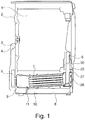
Figure 1 diagrammatically shows a vertical section of a condensation type laundry dryer machine according to the present invention; -
Figure 2 shows a cross-sectional view ofFigure 1 and particularly the portion of the conduit that conveys hot moist air from the laundry compartment to the condenser, the latter being shown in a longitudinal sectional view; -
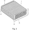
Figure 3 shows a perspective view of the condenser of the apparatus of the invention. - Even when this is not expressly stated, the individual features as described with reference to the particular embodiments shall be intended as auxiliary to and/or interchangeable with other features described with reference to other exemplary embodiments.
- Reference will be made hereinafter to a condensation type
laundry dryer machine 2, i.e. a laundry dryer machine that can heat the air required to dry clothes or laundry, using an electrical resistor, to introduce hot air into the drum. - Therefore, the disclosure does not address a laundry dryer machine of the heat-pump type.
- Referring to the afore-mentioned figures and particularly to
Figure 1 , it will be appreciated that the condensation typelaundry dryer machine 1 comprises a drum 1 (or drying compartment) in which the wet clothes to be dried is placed, and afirst conduit 3 for conveying a hot air flow toward the laundry. - For this purposes, the
machine 2 comprises a heater 4, e.g. a resistor, for heating said air flow, a first generator, e.g. a motorized fan 5, for generating said air flow, asecond conduit 6 for collecting the moist air flow from thelaundry compartment 1 and conveying it toward acondenser 7 which is located at the bottom 8 of themachine 2, as described in greater detail with reference toFigures 2 and3 . - Still referring to
Figure 1 , it will be appreciated that the laundry-dryer machine 2 comprises a second generator, not shown, for generating a cooling air flow and conveying it through an appropriate conduit, e.g. made of plastic, to said heat exchanger-basedcondenser 7. - The condensation water that comes out of the
condenser 7 is conveyed toward acollection chamber 9, which is in fluid communication with atank 10 by means of a connectingvalve 11, for the discharge of water that has been formed in thecondenser 7. - The dehumidified air that comes our of the
condenser 7 may be conveyed out of themachine 2 through an opening (not shown), e.g. formed on the bottom 8 of the machine. - According to the invention, the condenser 8 is of the heat exchanger-based type.
- According to a peculiar aspect, this
heat exchanger 7 is made of a metal material. - Furthermore, according to another aspect of the present invention, the
heat exchanger 7 cannot be removed from themachine 2 by the user unless for scheduled maintenance by skilled personnel. - For this purpose, particularly referring to
Figure 2 , ahousing 12 is provided at the bottom 8 of themachine 2. Thecondenser 7 is mechanically connected in thishousing 12 using connection means that lock the front frame of the condenser 8 to the abutment of theconduit 7. - These connection means are of removable type, to ensure the aforementioned scheduled maintenance to be performed by the skilled personnel.
- For example, the connection means are embodied by screws or bolts or similar elements.
- The
housing 12 comprises an inlet opening 13 having a peripheral abutment. -
Such housing 12 has an outlet opening for the flow of air or condensation water, as explained in greater detail hereinafter, which is referenced 14 and has in turn aperipheral abutment 15. - Referring now to
Figures 2-3 , the heat exchanger-based structure of thecondenser 7 comprises a tube bundle, e.g. composed of thirty-two sections of aluminum tubes, referenced 18, which have an outside diameter "D", for instance, of 16.00 mm and an inside diameter "d", for instance, of 14.00 mm, and have each a length "L", for instance, of 175.00 mm. - The
tube sections 18 are supported at their ends by theopposite heads -
Cooling fins 14 are mounted and mechanically fixed to the tube bundle as mentioned above, have each a thickness "s" of 0.15 mm, are also made of aluminum, and form a pack of forty-two fins. - The
first head 19 of the condenser, which faces theconduit 6 that conveys the hot and moist air flow from thedrum 1, when it is within thehousing 12, has arecess 21 within itscontour 22. The latter is engaged against the peripheral abutment of thehousing 12, when the condenser 8 is properly positioned therein. - Likewise, the
head 20 of thecondenser 7 comprises acontour 23 which is designed to engage at its front against theperipheral abutment 15 of the opening 14 of thehousing 12. - The
laundry dryer machine 2 comprises afirst filter 25 which is configured to filter any lint and fluff from the laundry, which are carried by the moist air flow, i.e. to prevent them from entering the pipes of the condenser thereby causing obstructions and leading to degradation of the energy efficiency of the machine. - The laundry-
dryer machine 2 comprises anadditional filter 24. Suchadditional filter 24 is placed in theconduit 7 downstream from thefilter 25 and in contact with theheat exchanger 7, preferably with itshead 19. - In one aspect, the
recess 21 receives afilter holder 26 which is designed to receive theadditional filter 24,such recess 21 being accessible through anopenable door 27, which is introduced into an opening 29 of thevertical wall 30 of themachine 2. - In one aspect, the
additional filter 23, which is housed in therecess 21 formed in thehead 19 of thecondenser 7, may be removed by the user for cleaning, once thedoor 27 has been opened, which makes it easily accessible through theconnection area 28. - This
filter 24 is added to thefilter 25, also removable for cleaning, which, in the prior art, is placed in theconduit 7 immediately downstream from thecompartment 1 in which the laundry is treated, and is designed to retain most of the lint that comes from the aforementioned compartment with the hot and moist air. - The
door 27 engages in the opening 29, with a seal interposed therebetween. - The wall of the
door 27 has a preferably curved shape and forms, in front of the opening 13 of thehousing 12, aconnection area 28 between the hot andmoist air conduit 6 and theopening 13. - The position of the
condenser 7 relative to the bottom 8 of the machine is preferably inclined at an angle of inclination α to facilitate the outflow of condensation water by gravity toward the collection anddischarge points 16. - Such angle α ranges from 2° to 6° and is preferably 3°, relative to the bottom wall 8 which extends in a direction of extension that is substantially parallel to the plane on which the
laundry dryer machine 2 stands. - In one aspect, the
condenser 7 in the laundry-dryer machine 2 assumes a condition in which it cannot be removed by the user for frequent cleaning operations, as the latter only mainly consist in cleaning the additionalremovable filter 24 which is placed immediately in front of the inlet opening of thecondenser 7 and is placed within a simple recess, and whose repositioning does not require alignment of conduit openings, introduction of seals and actuation of connecting members, which would be indispensable in case of removal of the condenser. - Furthermore, the omission of plastic materials in the condenser heads affords an improved behavior thereof at the operating temperatures of the machine, and hence also improved safety margins.
- Those skilled in the art will obviously appreciate that a number of changes and variants may be made to the arrangements as described hereinbefore to meet incidental and specific needs. All of these variants and changes fall within the scope of the invention, as defined in the following claims.
Claims (9)
- A condensation type laundry dryer machine (2) comprising a drum (1) in which the laundry to be dried is placed, a bottom wall (9), a first conduit (3) for conveying a flow of hot air toward said laundry (4) contained in the drum (1), a heater (4) for heating said air flow, a first motorized generator (5) for generating said air flow, a second conduit (6) for collecting the flow of moist air from the drum (1) and convey it toward a condenser (7), a first filter (25) placed in said second conduit (6) upstream from said condenser (7) for filtering the flint and fluff that are carried by the flow of said moist air that comes from the drum (1),
wherein said condenser (7) is a heat exchanger made of a metal material, and is located in a housing (12) formed in the lower portion of the laundry dryer machine, said condenser (7) being inclined at an angle (α) relative to the plane defined by the bottom wall (9) of the machine (2),
connection means for mechanically connecting said heat exchanger (7) to said housing (12),
said condenser (7) comprising a tube bundle (18) and cooling fins (16) mounted to said tube bundle (18), a first head (19) connected to said tube bundle (18) and facing said second conduit (6) and a second head (20) opposite to the first head (19),
characterized in that the end portions of the tube sections that form said tube bundle (18) are connected to said heads (19, 20) by an expanding step. - A condensation type laundry dryer machine (2) as claimed in claim 1, comprising a second filter (24) located in said second conduit (6) downstream from said first filter (25), said second filter (24) being placed in contact with said heat exchanger (7).
- A condensation type laundry dryer machine (2) as claimed in claim 2, wherein said second filter (24) is placed against said first head (19) of said heat exchanger (7).
- A condensation type laundry dryer machine (2) as claimed in claim 3, wherein said first head (19) of said heat exchanger (7) has a recess (21) and said second filter (24) is placed within said recess (21).
- A condensation type laundry dryer machine (2) as claimed in claim 3 or 4, wherein said first head (19) of said heat exchanger (7) has a contour (22) that engages against a peripheral abutment of the housing (12) when the condenser (7) is properly positioned in it.
- A condensation type laundry dryer machine (2) as claimed in claim 3, wherein said second head (20) of the condenser (7) has a contour (23) that is designed for front engagement against a peripheral abutment (15) of the opening of the housing (12).
- A condensation type laundry dryer machine (2) as claimed in claim 2, comprising a vertical wall (30) having an opening (29) with a door (27) for removal and introduction of said second filter (24).
- A condensation type laundry dryer machine (2) as claimed in claim 7, wherein said door (27) of the opening (29) for removal and introduction of said additional filter (24) has an arched shape which forms a connection area (28) between the conduit (6) for hot moist air and the opening (13) of the housing (12), in front of said opening (13) of the housing (12) of said condenser (7).
- A condensation type laundry dryer machine (2) as claimed in one or more of the preceding claims 3 to 8, wherein said first and second heads (19, 20) of said heat exchange condenser (7) consist of aluminum plates.
Applications Claiming Priority (1)
| Application Number | Priority Date | Filing Date | Title |
|---|---|---|---|
| IT102017000044782A IT201700044782A1 (en) | 2017-04-24 | 2017-04-24 | Condensing-type laundry drying machine |
Publications (2)
| Publication Number | Publication Date |
|---|---|
| EP3396054A1 true EP3396054A1 (en) | 2018-10-31 |
| EP3396054B1 EP3396054B1 (en) | 2020-01-29 |
Family
ID=59700140
Family Applications (1)
| Application Number | Title | Priority Date | Filing Date |
|---|---|---|---|
| EP18156757.9A Active EP3396054B1 (en) | 2017-04-24 | 2018-02-14 | A condensation type laundry dryer machine |
Country Status (2)
| Country | Link |
|---|---|
| EP (1) | EP3396054B1 (en) |
| IT (1) | IT201700044782A1 (en) |
Citations (5)
| Publication number | Priority date | Publication date | Assignee | Title |
|---|---|---|---|---|
| EP0219578A1 (en) | 1985-09-05 | 1987-04-29 | JAMES HOWDEN & COMPANY LIMITED | Centrifugal fans and blowers |
| EP2196578A1 (en) * | 2008-12-11 | 2010-06-16 | Electrolux Home Products Corporation N.V. | Laundry dryer with removable condenser |
| EP2366828A1 (en) * | 2010-03-17 | 2011-09-21 | Candy S.p.A. | Laundry dryer machine with improved condenser cooling system |
| EP2980306A1 (en) * | 2014-07-31 | 2016-02-03 | Indesit Company S.p.A. | Household drying appliance with improved inlet section of the drying fluid in the condenser |
| EP3124681A1 (en) * | 2015-07-30 | 2017-02-01 | Lg Electronics Inc. | Laundry treatment apparatus |
-
2017
- 2017-04-24 IT IT102017000044782A patent/IT201700044782A1/en unknown
-
2018
- 2018-02-14 EP EP18156757.9A patent/EP3396054B1/en active Active
Patent Citations (5)
| Publication number | Priority date | Publication date | Assignee | Title |
|---|---|---|---|---|
| EP0219578A1 (en) | 1985-09-05 | 1987-04-29 | JAMES HOWDEN & COMPANY LIMITED | Centrifugal fans and blowers |
| EP2196578A1 (en) * | 2008-12-11 | 2010-06-16 | Electrolux Home Products Corporation N.V. | Laundry dryer with removable condenser |
| EP2366828A1 (en) * | 2010-03-17 | 2011-09-21 | Candy S.p.A. | Laundry dryer machine with improved condenser cooling system |
| EP2980306A1 (en) * | 2014-07-31 | 2016-02-03 | Indesit Company S.p.A. | Household drying appliance with improved inlet section of the drying fluid in the condenser |
| EP3124681A1 (en) * | 2015-07-30 | 2017-02-01 | Lg Electronics Inc. | Laundry treatment apparatus |
Also Published As
| Publication number | Publication date |
|---|---|
| EP3396054B1 (en) | 2020-01-29 |
| IT201700044782A1 (en) | 2018-10-24 |
Similar Documents
| Publication | Publication Date | Title |
|---|---|---|
| US8266813B2 (en) | Exhaust air dryer with heat exchanger | |
| US7866057B2 (en) | Domestic appliance for the care of washed articles | |
| US8453720B2 (en) | Heat exchanger and condensing type laundry dryer having the same | |
| EP2230349B1 (en) | Filtering cartridge for home laundry driers and home laundry drier provided with said filtering cartridge | |
| JP6605040B2 (en) | Clothing condensation dryer and clothing condensation drying method | |
| BR102015027172A2 (en) | garment treatment apparatus | |
| US8056254B2 (en) | Tumble dryer with a lint filter | |
| EP2452009B1 (en) | Clothes drying apparatus | |
| WO2008102972A1 (en) | Heat exchanger module and ductless dryer having the same | |
| ITTO20121001A1 (en) | MACHINE SUITABLE FOR PERFORMING AT LEAST A WALL DRIING CYCLE | |
| CN206346058U (en) | For the condenser of clothes treatment device and the clothes treatment device with it | |
| CN204325738U (en) | The drying unit of nonwoven fabric | |
| CN107541891A (en) | A kind of washing-drying integral machine | |
| CN102011295A (en) | Drying machine | |
| EP3396054B1 (en) | A condensation type laundry dryer machine | |
| CN105780425A (en) | Washing machine and drying device thereof | |
| CN105239295A (en) | Drying apparatus of nonwoven fabric | |
| JPH04226700A (en) | household laundry dryer | |
| KR20080091660A (en) | Laundry dryer | |
| CN109654854A (en) | A kind of spiral air flow dryer of silk goods | |
| EP2366828B1 (en) | Laundry dryer machine with improved condenser cooling system | |
| CN203904692U (en) | Heat energy recovery device of cloth dyeing machine | |
| JP2013202159A (en) | Clothes dryer | |
| CH649111A5 (en) | DRY CLEANING MACHINE. | |
| RU2599369C2 (en) | Domestic electrical appliance |
Legal Events
| Date | Code | Title | Description |
|---|---|---|---|
| PUAI | Public reference made under article 153(3) epc to a published international application that has entered the european phase |
Free format text: ORIGINAL CODE: 0009012 |
|
| STAA | Information on the status of an ep patent application or granted ep patent |
Free format text: STATUS: THE APPLICATION HAS BEEN PUBLISHED |
|
| AK | Designated contracting states |
Kind code of ref document: A1 Designated state(s): AL AT BE BG CH CY CZ DE DK EE ES FI FR GB GR HR HU IE IS IT LI LT LU LV MC MK MT NL NO PL PT RO RS SE SI SK SM TR |
|
| AX | Request for extension of the european patent |
Extension state: BA ME |
|
| STAA | Information on the status of an ep patent application or granted ep patent |
Free format text: STATUS: REQUEST FOR EXAMINATION WAS MADE |
|
| 17P | Request for examination filed |
Effective date: 20190416 |
|
| RBV | Designated contracting states (corrected) |
Designated state(s): AL AT BE BG CH CY CZ DE DK EE ES FI FR GB GR HR HU IE IS IT LI LT LU LV MC MK MT NL NO PL PT RO RS SE SI SK SM TR |
|
| RIC1 | Information provided on ipc code assigned before grant |
Ipc: D06F 58/22 20060101ALN20190730BHEP Ipc: D06F 58/24 20060101AFI20190730BHEP |
|
| GRAP | Despatch of communication of intention to grant a patent |
Free format text: ORIGINAL CODE: EPIDOSNIGR1 |
|
| STAA | Information on the status of an ep patent application or granted ep patent |
Free format text: STATUS: GRANT OF PATENT IS INTENDED |
|
| INTG | Intention to grant announced |
Effective date: 20190912 |
|
| GRAS | Grant fee paid |
Free format text: ORIGINAL CODE: EPIDOSNIGR3 |
|
| GRAA | (expected) grant |
Free format text: ORIGINAL CODE: 0009210 |
|
| STAA | Information on the status of an ep patent application or granted ep patent |
Free format text: STATUS: THE PATENT HAS BEEN GRANTED |
|
| AK | Designated contracting states |
Kind code of ref document: B1 Designated state(s): AL AT BE BG CH CY CZ DE DK EE ES FI FR GB GR HR HU IE IS IT LI LT LU LV MC MK MT NL NO PL PT RO RS SE SI SK SM TR |
|
| REG | Reference to a national code |
Ref country code: GB Ref legal event code: FG4D |
|
| REG | Reference to a national code |
Ref country code: CH Ref legal event code: EP |
|
| REG | Reference to a national code |
Ref country code: AT Ref legal event code: REF Ref document number: 1228566 Country of ref document: AT Kind code of ref document: T Effective date: 20200215 |
|
| REG | Reference to a national code |
Ref country code: IE Ref legal event code: FG4D |
|
| REG | Reference to a national code |
Ref country code: DE Ref legal event code: R096 Ref document number: 602018002151 Country of ref document: DE |
|
| REG | Reference to a national code |
Ref country code: NL Ref legal event code: MP Effective date: 20200129 |
|
| PG25 | Lapsed in a contracting state [announced via postgrant information from national office to epo] |
Ref country code: PT Free format text: LAPSE BECAUSE OF FAILURE TO SUBMIT A TRANSLATION OF THE DESCRIPTION OR TO PAY THE FEE WITHIN THE PRESCRIBED TIME-LIMIT Effective date: 20200621 Ref country code: FI Free format text: LAPSE BECAUSE OF FAILURE TO SUBMIT A TRANSLATION OF THE DESCRIPTION OR TO PAY THE FEE WITHIN THE PRESCRIBED TIME-LIMIT Effective date: 20200129 Ref country code: NO Free format text: LAPSE BECAUSE OF FAILURE TO SUBMIT A TRANSLATION OF THE DESCRIPTION OR TO PAY THE FEE WITHIN THE PRESCRIBED TIME-LIMIT Effective date: 20200429 Ref country code: RS Free format text: LAPSE BECAUSE OF FAILURE TO SUBMIT A TRANSLATION OF THE DESCRIPTION OR TO PAY THE FEE WITHIN THE PRESCRIBED TIME-LIMIT Effective date: 20200129 |
|
| REG | Reference to a national code |
Ref country code: LT Ref legal event code: MG4D |
|
| PG25 | Lapsed in a contracting state [announced via postgrant information from national office to epo] |
Ref country code: GR Free format text: LAPSE BECAUSE OF FAILURE TO SUBMIT A TRANSLATION OF THE DESCRIPTION OR TO PAY THE FEE WITHIN THE PRESCRIBED TIME-LIMIT Effective date: 20200430 Ref country code: IS Free format text: LAPSE BECAUSE OF FAILURE TO SUBMIT A TRANSLATION OF THE DESCRIPTION OR TO PAY THE FEE WITHIN THE PRESCRIBED TIME-LIMIT Effective date: 20200529 Ref country code: SE Free format text: LAPSE BECAUSE OF FAILURE TO SUBMIT A TRANSLATION OF THE DESCRIPTION OR TO PAY THE FEE WITHIN THE PRESCRIBED TIME-LIMIT Effective date: 20200129 Ref country code: HR Free format text: LAPSE BECAUSE OF FAILURE TO SUBMIT A TRANSLATION OF THE DESCRIPTION OR TO PAY THE FEE WITHIN THE PRESCRIBED TIME-LIMIT Effective date: 20200129 Ref country code: LV Free format text: LAPSE BECAUSE OF FAILURE TO SUBMIT A TRANSLATION OF THE DESCRIPTION OR TO PAY THE FEE WITHIN THE PRESCRIBED TIME-LIMIT Effective date: 20200129 Ref country code: BG Free format text: LAPSE BECAUSE OF FAILURE TO SUBMIT A TRANSLATION OF THE DESCRIPTION OR TO PAY THE FEE WITHIN THE PRESCRIBED TIME-LIMIT Effective date: 20200429 |
|
| PG25 | Lapsed in a contracting state [announced via postgrant information from national office to epo] |
Ref country code: NL Free format text: LAPSE BECAUSE OF FAILURE TO SUBMIT A TRANSLATION OF THE DESCRIPTION OR TO PAY THE FEE WITHIN THE PRESCRIBED TIME-LIMIT Effective date: 20200129 |
|
| REG | Reference to a national code |
Ref country code: BE Ref legal event code: MM Effective date: 20200229 |
|
| PG25 | Lapsed in a contracting state [announced via postgrant information from national office to epo] |
Ref country code: LU Free format text: LAPSE BECAUSE OF NON-PAYMENT OF DUE FEES Effective date: 20200214 Ref country code: SM Free format text: LAPSE BECAUSE OF FAILURE TO SUBMIT A TRANSLATION OF THE DESCRIPTION OR TO PAY THE FEE WITHIN THE PRESCRIBED TIME-LIMIT Effective date: 20200129 Ref country code: LT Free format text: LAPSE BECAUSE OF FAILURE TO SUBMIT A TRANSLATION OF THE DESCRIPTION OR TO PAY THE FEE WITHIN THE PRESCRIBED TIME-LIMIT Effective date: 20200129 Ref country code: EE Free format text: LAPSE BECAUSE OF FAILURE TO SUBMIT A TRANSLATION OF THE DESCRIPTION OR TO PAY THE FEE WITHIN THE PRESCRIBED TIME-LIMIT Effective date: 20200129 Ref country code: SK Free format text: LAPSE BECAUSE OF FAILURE TO SUBMIT A TRANSLATION OF THE DESCRIPTION OR TO PAY THE FEE WITHIN THE PRESCRIBED TIME-LIMIT Effective date: 20200129 Ref country code: RO Free format text: LAPSE BECAUSE OF FAILURE TO SUBMIT A TRANSLATION OF THE DESCRIPTION OR TO PAY THE FEE WITHIN THE PRESCRIBED TIME-LIMIT Effective date: 20200129 Ref country code: ES Free format text: LAPSE BECAUSE OF FAILURE TO SUBMIT A TRANSLATION OF THE DESCRIPTION OR TO PAY THE FEE WITHIN THE PRESCRIBED TIME-LIMIT Effective date: 20200129 Ref country code: MC Free format text: LAPSE BECAUSE OF FAILURE TO SUBMIT A TRANSLATION OF THE DESCRIPTION OR TO PAY THE FEE WITHIN THE PRESCRIBED TIME-LIMIT Effective date: 20200129 Ref country code: CZ Free format text: LAPSE BECAUSE OF FAILURE TO SUBMIT A TRANSLATION OF THE DESCRIPTION OR TO PAY THE FEE WITHIN THE PRESCRIBED TIME-LIMIT Effective date: 20200129 Ref country code: DK Free format text: LAPSE BECAUSE OF FAILURE TO SUBMIT A TRANSLATION OF THE DESCRIPTION OR TO PAY THE FEE WITHIN THE PRESCRIBED TIME-LIMIT Effective date: 20200129 |
|
| REG | Reference to a national code |
Ref country code: DE Ref legal event code: R097 Ref document number: 602018002151 Country of ref document: DE |
|
| REG | Reference to a national code |
Ref country code: AT Ref legal event code: MK05 Ref document number: 1228566 Country of ref document: AT Kind code of ref document: T Effective date: 20200129 |
|
| PLBE | No opposition filed within time limit |
Free format text: ORIGINAL CODE: 0009261 |
|
| STAA | Information on the status of an ep patent application or granted ep patent |
Free format text: STATUS: NO OPPOSITION FILED WITHIN TIME LIMIT |
|
| 26N | No opposition filed |
Effective date: 20201030 |
|
| PG25 | Lapsed in a contracting state [announced via postgrant information from national office to epo] |
Ref country code: IE Free format text: LAPSE BECAUSE OF NON-PAYMENT OF DUE FEES Effective date: 20200214 Ref country code: AT Free format text: LAPSE BECAUSE OF FAILURE TO SUBMIT A TRANSLATION OF THE DESCRIPTION OR TO PAY THE FEE WITHIN THE PRESCRIBED TIME-LIMIT Effective date: 20200129 |
|
| PG25 | Lapsed in a contracting state [announced via postgrant information from national office to epo] |
Ref country code: SI Free format text: LAPSE BECAUSE OF FAILURE TO SUBMIT A TRANSLATION OF THE DESCRIPTION OR TO PAY THE FEE WITHIN THE PRESCRIBED TIME-LIMIT Effective date: 20200129 Ref country code: PL Free format text: LAPSE BECAUSE OF FAILURE TO SUBMIT A TRANSLATION OF THE DESCRIPTION OR TO PAY THE FEE WITHIN THE PRESCRIBED TIME-LIMIT Effective date: 20200129 Ref country code: BE Free format text: LAPSE BECAUSE OF NON-PAYMENT OF DUE FEES Effective date: 20200229 |
|
| PG25 | Lapsed in a contracting state [announced via postgrant information from national office to epo] |
Ref country code: LI Free format text: LAPSE BECAUSE OF NON-PAYMENT OF DUE FEES Effective date: 20210228 Ref country code: CH Free format text: LAPSE BECAUSE OF NON-PAYMENT OF DUE FEES Effective date: 20210228 |
|
| PG25 | Lapsed in a contracting state [announced via postgrant information from national office to epo] |
Ref country code: MT Free format text: LAPSE BECAUSE OF FAILURE TO SUBMIT A TRANSLATION OF THE DESCRIPTION OR TO PAY THE FEE WITHIN THE PRESCRIBED TIME-LIMIT Effective date: 20200129 Ref country code: CY Free format text: LAPSE BECAUSE OF FAILURE TO SUBMIT A TRANSLATION OF THE DESCRIPTION OR TO PAY THE FEE WITHIN THE PRESCRIBED TIME-LIMIT Effective date: 20200129 |
|
| PG25 | Lapsed in a contracting state [announced via postgrant information from national office to epo] |
Ref country code: MK Free format text: LAPSE BECAUSE OF FAILURE TO SUBMIT A TRANSLATION OF THE DESCRIPTION OR TO PAY THE FEE WITHIN THE PRESCRIBED TIME-LIMIT Effective date: 20200129 Ref country code: AL Free format text: LAPSE BECAUSE OF FAILURE TO SUBMIT A TRANSLATION OF THE DESCRIPTION OR TO PAY THE FEE WITHIN THE PRESCRIBED TIME-LIMIT Effective date: 20200129 |
|
| REG | Reference to a national code |
Ref country code: DE Ref legal event code: R081 Ref document number: 602018002151 Country of ref document: DE Owner name: CANDY S.P.A., IT Free format text: FORMER OWNER: CANDY S.P.A., MONZA (MB), IT |
|
| PGFP | Annual fee paid to national office [announced via postgrant information from national office to epo] |
Ref country code: DE Payment date: 20250225 Year of fee payment: 8 |
|
| PGFP | Annual fee paid to national office [announced via postgrant information from national office to epo] |
Ref country code: FR Payment date: 20250130 Year of fee payment: 8 |
|
| PGFP | Annual fee paid to national office [announced via postgrant information from national office to epo] |
Ref country code: IT Payment date: 20250120 Year of fee payment: 8 Ref country code: GB Payment date: 20250220 Year of fee payment: 8 |
|
| PGFP | Annual fee paid to national office [announced via postgrant information from national office to epo] |
Ref country code: TR Payment date: 20250210 Year of fee payment: 8 |