EP3395237B1 - Improvements in or relating to in-vehicle monitoring - Google Patents
Improvements in or relating to in-vehicle monitoring Download PDFInfo
- Publication number
- EP3395237B1 EP3395237B1 EP18168310.3A EP18168310A EP3395237B1 EP 3395237 B1 EP3395237 B1 EP 3395237B1 EP 18168310 A EP18168310 A EP 18168310A EP 3395237 B1 EP3395237 B1 EP 3395237B1
- Authority
- EP
- European Patent Office
- Prior art keywords
- image
- subject
- video image
- interest
- signal
- Prior art date
- Legal status (The legal status is an assumption and is not a legal conclusion. Google has not performed a legal analysis and makes no representation as to the accuracy of the status listed.)
- Active
Links
Images


Classifications
-
- A—HUMAN NECESSITIES
- A61—MEDICAL OR VETERINARY SCIENCE; HYGIENE
- A61B—DIAGNOSIS; SURGERY; IDENTIFICATION
- A61B5/00—Measuring for diagnostic purposes; Identification of persons
- A61B5/72—Signal processing specially adapted for physiological signals or for diagnostic purposes
- A61B5/7203—Signal processing specially adapted for physiological signals or for diagnostic purposes for noise prevention, reduction or removal
- A61B5/7207—Signal processing specially adapted for physiological signals or for diagnostic purposes for noise prevention, reduction or removal of noise induced by motion artifacts
-
- G—PHYSICS
- G06—COMPUTING OR CALCULATING; COUNTING
- G06V—IMAGE OR VIDEO RECOGNITION OR UNDERSTANDING
- G06V20/00—Scenes; Scene-specific elements
- G06V20/50—Context or environment of the image
- G06V20/59—Context or environment of the image inside of a vehicle, e.g. relating to seat occupancy, driver state or inner lighting conditions
- G06V20/597—Recognising the driver's state or behaviour, e.g. attention or drowsiness
-
- G—PHYSICS
- G06—COMPUTING OR CALCULATING; COUNTING
- G06T—IMAGE DATA PROCESSING OR GENERATION, IN GENERAL
- G06T5/00—Image enhancement or restoration
- G06T5/73—Deblurring; Sharpening
-
- G—PHYSICS
- G06—COMPUTING OR CALCULATING; COUNTING
- G06T—IMAGE DATA PROCESSING OR GENERATION, IN GENERAL
- G06T7/00—Image analysis
- G06T7/0002—Inspection of images, e.g. flaw detection
- G06T7/0012—Biomedical image inspection
- G06T7/0014—Biomedical image inspection using an image reference approach
- G06T7/0016—Biomedical image inspection using an image reference approach involving temporal comparison
-
- G—PHYSICS
- G06—COMPUTING OR CALCULATING; COUNTING
- G06T—IMAGE DATA PROCESSING OR GENERATION, IN GENERAL
- G06T7/00—Image analysis
- G06T7/20—Analysis of motion
- G06T7/246—Analysis of motion using feature-based methods, e.g. the tracking of corners or segments
- G06T7/248—Analysis of motion using feature-based methods, e.g. the tracking of corners or segments involving reference images or patches
-
- G—PHYSICS
- G06—COMPUTING OR CALCULATING; COUNTING
- G06V—IMAGE OR VIDEO RECOGNITION OR UNDERSTANDING
- G06V20/00—Scenes; Scene-specific elements
- G06V20/40—Scenes; Scene-specific elements in video content
- G06V20/46—Extracting features or characteristics from the video content, e.g. video fingerprints, representative shots or key frames
-
- A—HUMAN NECESSITIES
- A61—MEDICAL OR VETERINARY SCIENCE; HYGIENE
- A61B—DIAGNOSIS; SURGERY; IDENTIFICATION
- A61B5/00—Measuring for diagnostic purposes; Identification of persons
- A61B5/0059—Measuring for diagnostic purposes; Identification of persons using light, e.g. diagnosis by transillumination, diascopy, fluorescence
- A61B5/0077—Devices for viewing the surface of the body, e.g. camera, magnifying lens
-
- A—HUMAN NECESSITIES
- A61—MEDICAL OR VETERINARY SCIENCE; HYGIENE
- A61B—DIAGNOSIS; SURGERY; IDENTIFICATION
- A61B5/00—Measuring for diagnostic purposes; Identification of persons
- A61B5/02—Detecting, measuring or recording for evaluating the cardiovascular system, e.g. pulse, heart rate, blood pressure or blood flow
- A61B5/024—Measuring pulse rate or heart rate
- A61B5/02416—Measuring pulse rate or heart rate using photoplethysmograph signals, e.g. generated by infrared radiation
-
- A—HUMAN NECESSITIES
- A61—MEDICAL OR VETERINARY SCIENCE; HYGIENE
- A61B—DIAGNOSIS; SURGERY; IDENTIFICATION
- A61B5/00—Measuring for diagnostic purposes; Identification of persons
- A61B5/16—Devices for psychotechnics; Testing reaction times ; Devices for evaluating the psychological state
- A61B5/18—Devices for psychotechnics; Testing reaction times ; Devices for evaluating the psychological state for vehicle drivers or machine operators
-
- A—HUMAN NECESSITIES
- A61—MEDICAL OR VETERINARY SCIENCE; HYGIENE
- A61B—DIAGNOSIS; SURGERY; IDENTIFICATION
- A61B5/00—Measuring for diagnostic purposes; Identification of persons
- A61B5/68—Arrangements of detecting, measuring or recording means, e.g. sensors, in relation to patient
- A61B5/6887—Arrangements of detecting, measuring or recording means, e.g. sensors, in relation to patient mounted on external non-worn devices, e.g. non-medical devices
- A61B5/6893—Cars
-
- A—HUMAN NECESSITIES
- A61—MEDICAL OR VETERINARY SCIENCE; HYGIENE
- A61B—DIAGNOSIS; SURGERY; IDENTIFICATION
- A61B5/00—Measuring for diagnostic purposes; Identification of persons
- A61B5/74—Details of notification to user or communication with user or patient; User input means
- A61B5/7475—User input or interface means, e.g. keyboard, pointing device, joystick
- A61B5/748—Selection of a region of interest, e.g. using a graphics tablet
- A61B5/7485—Automatic selection of region of interest
-
- G—PHYSICS
- G06—COMPUTING OR CALCULATING; COUNTING
- G06T—IMAGE DATA PROCESSING OR GENERATION, IN GENERAL
- G06T2207/00—Indexing scheme for image analysis or image enhancement
- G06T2207/10—Image acquisition modality
- G06T2207/10016—Video; Image sequence
-
- G—PHYSICS
- G06—COMPUTING OR CALCULATING; COUNTING
- G06T—IMAGE DATA PROCESSING OR GENERATION, IN GENERAL
- G06T2207/00—Indexing scheme for image analysis or image enhancement
- G06T2207/20—Special algorithmic details
- G06T2207/20172—Image enhancement details
- G06T2207/20201—Motion blur correction
-
- G—PHYSICS
- G06—COMPUTING OR CALCULATING; COUNTING
- G06T—IMAGE DATA PROCESSING OR GENERATION, IN GENERAL
- G06T2207/00—Indexing scheme for image analysis or image enhancement
- G06T2207/30—Subject of image; Context of image processing
- G06T2207/30004—Biomedical image processing
- G06T2207/30076—Plethysmography
-
- G—PHYSICS
- G06—COMPUTING OR CALCULATING; COUNTING
- G06T—IMAGE DATA PROCESSING OR GENERATION, IN GENERAL
- G06T2207/00—Indexing scheme for image analysis or image enhancement
- G06T2207/30—Subject of image; Context of image processing
- G06T2207/30196—Human being; Person
-
- G—PHYSICS
- G06—COMPUTING OR CALCULATING; COUNTING
- G06T—IMAGE DATA PROCESSING OR GENERATION, IN GENERAL
- G06T2207/00—Indexing scheme for image analysis or image enhancement
- G06T2207/30—Subject of image; Context of image processing
- G06T2207/30248—Vehicle exterior or interior
- G06T2207/30268—Vehicle interior
-
- G—PHYSICS
- G06—COMPUTING OR CALCULATING; COUNTING
- G06V—IMAGE OR VIDEO RECOGNITION OR UNDERSTANDING
- G06V40/00—Recognition of biometric, human-related or animal-related patterns in image or video data
- G06V40/10—Human or animal bodies, e.g. vehicle occupants or pedestrians; Body parts, e.g. hands
- G06V40/16—Human faces, e.g. facial parts, sketches or expressions
- G06V40/161—Detection; Localisation; Normalisation
- G06V40/167—Detection; Localisation; Normalisation using comparisons between temporally consecutive images
Definitions
- the present invention relates to improvements in or relating to in-vehicle monitoring and in particular to video monitoring of the operator of a vehicle to obtain an estimate of a vital sign, such as a heart rate or breathing rate, of the operator.
- a vital sign such as a heart rate or breathing rate
- Video monitoring of vehicle operators has been of interest for many years.
- various systems have been proposed for automatically detecting deteriorations in alertness caused by, for example, health problems or drowsiness.
- the results may be stored or, preferably, an alarm can be generated to alert the operator or the controls of the vehicle may be operated to bring the vehicle to a safe condition.
- PPGi photoplethysmographic
- a problem is that most demonstrations of the estimate of a subject's vital signs from video images are performed in very controlled conditions. Usually lighting is carefully arranged to be stable and even and the subject is requested to remain still during the period of video image capture. While the prior art demonstrates that it is possible to obtain reasonable estimates of heart rate and breathing rate in such conditions, in practical situations, particularly in moving vehicles, conditions are far from ideal and it is extremely difficult to obtain reasonable estimates of a subject's vital signs. In particular, illumination levels often vary spatially, while the motion of the vehicle induces motion in the subject, such that the level of illumination reaching a given region of the patient's skin varies temporally; even if the illumination levels relative to the car are temporally constant.
- PPGi analysis techniques normally rely on the definition of one or more regions of interest on skin areas of the subject.
- the colour and/or luminance values from the regions of interest is used to provide a signal from which the PPG signal is to be obtained.
- this will introduce noise into the signal. Therefore it has been proposed to perform image registration on the video image so that the subject's position in the image is consistent (while the background appears to move), allowing the region of interest to be positioned at the same place within each image frame.
- the subject is moving within the spatially varying illumination field within the vehicle, although the subject's position in the image frame is stable, the brightness of the subject will seem to vary. Thus the movement of the subject will cause a variation in illumination which contaminates the image signal from which the PPG signal is to be obtained.
- An object of the invention is to provide for a method of processing a video image of a human subject to allow estimation of a vital sign, such as heart rate or breathing rate of the subject, which allows reduction of artifacts caused by motion-induced illumination variations and thus provides a better estimate of the vital sign.
- a vital sign such as heart rate or breathing rate of the subject
- the present invention provides a method as defined in claim 1 and an apparatus as defined in claim 11.
- the step of analysing the video image to obtain a motion transformation may comprise performing a motion correction process, such as image registration, which produces a motion corrected video image and the motion transformation.
- the region of interest is defined in the video image before the step of analysing the video image to obtain a motion transformation
- the step of analysing the video image to obtain a motion transformation comprises tracking the region of interest through the sequence of image frames.
- the varying position of the region of interest represents the motion transformation.
- the motion transformation in general has at least two and no more than eight parameters.
- the motion transformation is a projective transformation, for example which returns eight parameters, being the three orthogonal translation directions of the subject, rotations of the subject around three orthogonal axes, and two parameters representing camera position.
- the transformation may be an affine transformation for example.
- the motion transformation may have parameters corresponding to the position of the region of interest, e.g. the position of the vertices of the region of interest, or some other feature of the region of interest. For a triangular region of interest there would therefore be six parameters - corresponding to the x,y coordinates of each vertex. This is then equivalent to an affine transformation; accounting for x y translation, tilt forwards, tilt sideways, in plane rotation and scale changes (moving towards or away from the camera).
- the step of fitting the function of the motion transformation parameters to the image intensity signal may comprise simple linear regression fitting, or quadratic regression fitting.
- regions of interest defined on the subject, preferably on automatically detected areas on the subject's skin. Such areas may be automatically detected by virtue of detecting skin tone or recognising the shape of the subject in the image, or by defining them in relation to image features automatically detected and tracked through the video image.
- An intensity representative signal may be formed for each region of interest as an average or sum of pixel values in that region. It may be based on the luminance of the image or a signal derived from one or more colour channels of the video signal.
- a single vital sign e.g. heart rate
- estimate the method starts by taking n adjacent frames.
- the motion transformation is then obtained, offering 8 transformation signals, each of length n.
- 8 transformation signals each of length n.
- m intensity signals each of length n.
- Each of these signals is then fitted against the 8 transformation signals.
- This provides m residual signals, each of length n.
- These residual signals may then be combined into a final signal of length n from which the vital sign, e.g. heart rate, is extracted, or each signal can be used to extract an estimate and a signal quality index, with the estimates then being combined as a function of their signal quality indices.
- the image intensity signal preferably contains a PPG signal relating to variations in the transmissivity or reflectivity of the skin as the amount of oxygenated blood in the skin capillaries varies with heart beat.
- the video image is the image of a subject in a vehicle, such as the operator of the vehicle, e.g. driver or pilot.
- the invention is applicable to other monitoring situations where the subject is in motion in a non-uniform illumination field such as a subject sitting or standing with their head unsupported.
- an apparatus for processing a video image in accordance with the method above may include an image processor and a data store and/or display for storing the results and/or displaying them.
- the apparatus may include an alarm and/or an interface to the controls of the vehicle or machine to allow it to be brought into a safe condition in the event of the subject's vital signs being sufficiently abnormal.
- the invention also extends to a video monitoring system comprising a video camera and such an image processing apparatus, and to a vehicle having such a video monitoring system installed therein.
- the method of the invention may be embodied in computer software which when executed on a programmed computer system processes captured video images in accordance with the method above to obtain and output an estimate of the vital sign of the subject.
- the invention extends to computer-readable media storing such computer software and to computer systems programmed with such software.
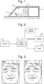
- Figure 1 schematically illustrates a vehicle 3 occupied by an operator 1 who is the subject of a video image captured by video camera 5.
- the video camera 5 may be a standard colour or monochrome digital video camera producing a monochrome or colour digital video signal consisting of a sequence of image frames, typically at a frame rate of 20 frames per second for example.
- the camera 5 supplies its output (a video image) to an image processor 10 which processes the video image as will be described later to obtain an estimate of a vital sign of the subject 1.
- This estimate may be output via a display 12 and/or recorded in a data store 14.
- the image processor may also supply an output to the vehicle controls 7 if it is desired to provide some form of alarm or alert through the vehicle controls or to operate the vehicle to bring it into a safe condition.
- the analysis of the video image by the image processor 10 to obtain a PPG signal relies upon analysing the image in a skin region of the subject 1. This is achieved by locating one or more areas in each video image frame which are images of the subject's skin and defining one or more regions of interest in such skin regions. Such regions of interest are usually square or rectangular and Figure 3 illustrates two image frames from a video image with a region of interest shown on the forehead of the subject as a white rectangle. Because the operator of the vehicle is subject to the vehicle's movements, the subject moves considerably within the field of view of the camera and so appears in different positions in each frame of the image. In order to obtain a good PPG signal it is necessary for the region of interest to remain consistently positioned on the subject. Therefore it is normal to perform an image registration process on the video image so that the subject appears to remain still, while the background moves. Such image registration processes are well-known.
- the image registration process involves the application of the projective transformation to the second frame, that minimizes the differences between the overlapping region of the second frame and a pre-specified sub-region of the first frame.
- the motion transformations can be applied to the video images to produce a set of motion-compensated video images in which the subject remains apparently still, but the background appears to move. This allows the region of interest to be positioned at the same position in each frame and thus to represent the same area of skin of the subject throughout the video image.
- the calculated motion transformation is used to form an illumination model of how the illumination on the face has changed because of the motion of the subject relative to the camera.
- the difference between the modelled illumination and the intensity variation detected in the region of interest on the skin should then have a clearer PPG component.
- Conventional methods for estimating the vital signs of the subject, such as heart rate or breathing rate from the signal will then produce a better estimate because of the reduction of noise from varying illumination.
- step 100 a video image consisting of successive image frames is captured and in step 102 a time window of n adjacent frames is selected (for example n may be 200). Then in step 104 a conventional image registration process is executed. This process involves calculating in step 106 a motion transformation representing the movement of the subject between adjacent image frames of the video image and in step 108 this transformation is used to compensate the video images for the subject motion to place the subject in the same position in each frame.
- step 110 one or more regions of interest on skin areas of the subject in the motion-compensated video image are defined and in step 112 an intensity-representative signal is obtained from the region or each region of interest.
- Such signals may be obtained by averaging or summing the pixel values in the region of interest and this may be conducted on a single monochrome or colour channel or on a function, such as a ratio, of multiple colour channels of a video signal.
- step 114 the motion transformation calculated in step 106 is used to form an illumination model of how the illumination on the subject has changed as a result of the subject's movement.
- an illumination model is a linear combination of the cumulative transformation parameters, that is to say, each parameter is multiplied by a coefficient and added together.
- Illumination L n k 0 + ⁇ i k i T ni
- the coefficients k 0 , k 1 , ..., k 8 are obtained through the minimization of ⁇ n (I n -L n ) 2 , where I n is the mean intensity of the or each region of interest in the n th transformed frame.
- Illumination L n k 0 + ⁇ i k i T ni + ⁇ i k i + 8 T ni 2
- the residuals i.e. the remaining differences between the fitted function and the intensity signal can be taken as a new residuals signal which still includes the PPG signal.
- the PPG signal will be stronger in this residuals signal because the main variations in illumination resulting from the subject's movement have been removed.
- these residuals are taken as an illumination-compensated signal, one for each region of interest.
- any of the known techniques for analysing a video image signal to derive a PPG signal may be applied to the illumination-compensated residuals signal(s) to derive an estimate of a vital sign such as heart rate or breathing rate.
- this may involve combining the illumination-compensated residuals signal(s) and then analysing the result to find the PPG signal and a vital sign estimate, or analysing them individually and combining the resulting estimates.
- the estimated vital sign may be displayed and/or output and/or stored. Possible actions based on the vital sign are alarming or alerting the operator if the vital signs are abnormal or executing some control of the vehicle.
- step 122 the time window of n frames is shifted by a time step, such as one second, to obtain a new time window of n frames and the process is repeated to obtain a new vital sign estimate.
- Figure 5 illustrates the results of applying the first embodiment of the invention to a video image sequence of a subject under spatially variable illumination.
- the top plot in Figure 5 shows the original motion-compensated intensity signal in blue (solid) and the predicted illumination formed by fitting a quadratic function of the motion cumulative transform parameters to that intensity signal.
- the residuals i.e. the difference between the two, is illustrated in the middle plot and this forms an illumination-compensated signal which includes a PPG component.
- the bottom plot shows a Fast Fourier Transform (FFT) analysis of that signal with the realistic physiological frequency bands for heart rate illustrated between the two pairs of vertical lines.
- the FFT representation of the residuals in the bottom plot shows strong signals in the two physiologically-possible ranges for heart beat.
- FFT Fast Fourier Transform
- Figure 6 schematically illustrates an alternative embodiment of the invention in which instead of motion correcting the image and then defining the region of interest, the region of interest is defined first and then tracked through the video image, its movement representing the movement of the subject and thus providing the motion transformation signal and motion transformation parameters.
- a time window of n adjacent frames of the video image captured in step 100 is selected and in step 604 one or more regions of interest are defined on a skin area of the subject in the image.
- One automatic way of defining such regions of interest will be described below with reference to Figures 7 and 8 , but other ways, such as detecting areas of skin by their colour or by recognising human shapes in the image are known and explained in the art.
- the position of the or each region of interest is tracked through the time window in step 606 and in step 608 the movement is taken as the motion transformation signal whose parameters represent subject movement in the image.
- an intensity signal is obtained from the or each region of interest in the same way as in the first embodiment, for example by averaging or summing the pixel values in the region of interest, and then the method proceeds as in the first embodiment by fitting a function of the motion transformation parameters to the intensity signal for the or each region of interest and taking the residuals of the fitting process as an illumination-compensated PPG signal (step 116).
- This illumination-compensated PPG signal is analysed in step 118 to obtain an estimate of at least one vital sign, which is displayed and output or stored in step 120.
- the process then moves the time window by a time step, for example one second in step 122 and repeats.
- Figure 8 illustrates in more detail the signal processing for one way of defining regions of interest and obtaining intensity and motion transformation signals of steps 604, 606, 608 and 112.
- the average frame intensity of each frame is set to a constant value to reduce image flicker, e.g. by multiplying each pixel value by the mean pixel value over the whole sequence and dividing by a constant to scale the values as desired (e.g. 0-255 for 8 bit values).
- step 801 feature points in the video sequence are detected.
- feature points consisting of recognisable geometrical shapes such as corner or edges can be detected based, for example, on the gradient of intensity variation in one or two dimensions, and any such conventional algorithm which identifies image feature points can be used in this invention.
- the feature points are tracked through the whole batch of video frames under consideration, e.g. by using a conventional tracking algorithm such as KLT tracking, to form "tracks" consisting of the x and y coordinates of each feature point in each image frame through the sequence.
- the next steps of the process are conducted on a time window of the video sequence, and then the process will be repeated for another time window shifted along by some time increment.
- the successive windows may overlap, for example if a nine second window is stepped forwards by one second each time the overlap will be eight seconds.
- step 806 the central frame of the time window is taken and Delaunay triangulation is performed on the feature points.
- Delaunay triangulation is a process which creates triangles favouring large internal angles.
- Figure 7(A) illustrates schematically three successive frames at times n - 1, n and n + 1 with the central frame n having five feature points 20 connected to form triangles.
- the position of the feature points varies from frame-to-frame. Having formed the triangles in the central frame of the sequence, the same triangles are formed in each other frame of the sequence (i.e. the same feature points are connected together) so that each triangle is defined throughout the whole nine second time window by three KLT tracks specifying the positions of its vertices.
- step 808 the in-circle 22 of each triangle is formed and then a square 24 concentric with the in-circle 22 is formed, aligned with the x and y axes of the image frame and with a side length equal to the diameter of the in-circle.
- a square 24 then constitutes a region of interest from which a signal will be obtained for further processing.
- the intensity in each region of interest in each frame is calculated (the sum of all the pixel intensity values) and the intensity for each square region of interest (ROI) through the time window corresponds to a signal (i1 to im) to be processed.
- a signal i1 to im
- the image intensity of each ROI through the frame sequence will typically vary as schematically illustrated in Figure 7(B) .
- the location (x, y) of each region of interest (for example the centre or a specified corner of each square) is also obtained and represents the movement of the subject.
- the intensity signals and movements of each region of interest are then output as time signals as illustrated in step 112.
- the intensity and movement signals output from the process of Figure 8 are input to step 114 of Figure 6 .
Landscapes
- Engineering & Computer Science (AREA)
- Health & Medical Sciences (AREA)
- Physics & Mathematics (AREA)
- General Physics & Mathematics (AREA)
- Theoretical Computer Science (AREA)
- Computer Vision & Pattern Recognition (AREA)
- Life Sciences & Earth Sciences (AREA)
- Multimedia (AREA)
- Signal Processing (AREA)
- General Health & Medical Sciences (AREA)
- Medical Informatics (AREA)
- Biomedical Technology (AREA)
- Artificial Intelligence (AREA)
- Pathology (AREA)
- Psychiatry (AREA)
- Heart & Thoracic Surgery (AREA)
- Physiology (AREA)
- Molecular Biology (AREA)
- Surgery (AREA)
- Animal Behavior & Ethology (AREA)
- Biophysics (AREA)
- Public Health (AREA)
- Veterinary Medicine (AREA)
- Nuclear Medicine, Radiotherapy & Molecular Imaging (AREA)
- Radiology & Medical Imaging (AREA)
- Quality & Reliability (AREA)
- Measurement Of The Respiration, Hearing Ability, Form, And Blood Characteristics Of Living Organisms (AREA)
- Measuring And Recording Apparatus For Diagnosis (AREA)
Description
- The present invention relates to improvements in or relating to in-vehicle monitoring and in particular to video monitoring of the operator of a vehicle to obtain an estimate of a vital sign, such as a heart rate or breathing rate, of the operator.
- Video monitoring of vehicle operators, such as car, truck or train drivers, aeroplane pilots and so on has been of interest for many years. As well as simply recording video of the operator to monitor their behaviour and state of alertness, various systems have been proposed for automatically detecting deteriorations in alertness caused by, for example, health problems or drowsiness. The results may be stored or, preferably, an alarm can be generated to alert the operator or the controls of the vehicle may be operated to bring the vehicle to a safe condition.
- More recently, proposals have been made for analysing video images of human subjects and in particular analysing variations in skin tone in the image to detect a photoplethysmographic (PPGi) signal in the image representing the heart rate of the subject. Such a PPGi signal also carries a breathing rate modulation, allowing an estimate of both the heart rate and breathing rate in some circumstances. The video image of the subject can also be frequency analysed to detect movements in the expected frequency range for breathing rate or heart rate (such as movements of the chest or shoulders), and an estimate of breathing rate obtained from such movements. Such techniques are described in
WO-A-2013/027027 . - A problem, however, is that most demonstrations of the estimate of a subject's vital signs from video images are performed in very controlled conditions. Usually lighting is carefully arranged to be stable and even and the subject is requested to remain still during the period of video image capture. While the prior art demonstrates that it is possible to obtain reasonable estimates of heart rate and breathing rate in such conditions, in practical situations, particularly in moving vehicles, conditions are far from ideal and it is extremely difficult to obtain reasonable estimates of a subject's vital signs. In particular, illumination levels often vary spatially, while the motion of the vehicle induces motion in the subject, such that the level of illumination reaching a given region of the patient's skin varies temporally; even if the illumination levels relative to the car are temporally constant.
- PPGi analysis techniques normally rely on the definition of one or more regions of interest on skin areas of the subject. The colour and/or luminance values from the regions of interest is used to provide a signal from which the PPG signal is to be obtained. However if the region of interest moves to a different skin region of the subject, this will introduce noise into the signal. Therefore it has been proposed to perform image registration on the video image so that the subject's position in the image is consistent (while the background appears to move), allowing the region of interest to be positioned at the same place within each image frame. However because the subject is moving within the spatially varying illumination field within the vehicle, although the subject's position in the image frame is stable, the brightness of the subject will seem to vary. Thus the movement of the subject will cause a variation in illumination which contaminates the image signal from which the PPG signal is to be obtained.
- The same problem of a subject's movement causing a variation in illumination occurs in any video monitoring situation where the subject is moving and the illumination field is not completely spatially uniform.
- The paper by BLOCHER TIMON ET AL: "An online PPGI approach for camera based heart rate monitoring using beat-to-beat detection", (2017 IEEE SENSORS APPLICATIONS SYMPOSIUM (SAS), IEEE, 13 March 2017 (2017-03-13), pages 1-6, XP033084556, DOI: 10.1109/SAS.2017.7894052) discloses a method on which the precharacterizing portion of
claim 1 is based. - The paper by AMELARD ROBERT ET AL: "Illumination-compensated non-contact imaging photoplethysmography via dual-mode temporally coded illumination", PROGRESS IN BIOMEDICAL OPTICS AND IMAGING, (SPIE - INTERNATIONAL SOCIETY FOR OPTICAL ENGINEERING, BELLINGHAM, WA, US, vol. 9316, 5 March 2015 (2015-03-05), pages 931607-931607, XP060048832, ISSN: 1605-7422, DOI: 10.1117/12.2078197 ISBN: 978-1-5106-0027-0) discloses a method of compensating for ambient illumination variations ibn PPGi by using time-coded illumination.
US-A1-2013/324875 discloses an image-based method of respiration detection by illuminating the thoracic region of a subject with structured illumination allowing the measurement of variations in 3D volumes reconstructed by processing the image. - An object of the invention is to provide for a method of processing a video image of a human subject to allow estimation of a vital sign, such as heart rate or breathing rate of the subject, which allows reduction of artifacts caused by motion-induced illumination variations and thus provides a better estimate of the vital sign.
- In more detail the present invention provides a method as defined in
claim 1 and an apparatus as defined in claim 11. - The step of analysing the video image to obtain a motion transformation may comprise performing a motion correction process, such as image registration, which produces a motion corrected video image and the motion transformation.
- Alternatively, the region of interest is defined in the video image before the step of analysing the video image to obtain a motion transformation, and the step of analysing the video image to obtain a motion transformation comprises tracking the region of interest through the sequence of image frames. Thus the varying position of the region of interest represents the motion transformation.
- The motion transformation in general has at least two and no more than eight parameters. In one example the motion transformation is a projective transformation, for example which returns eight parameters, being the three orthogonal translation directions of the subject, rotations of the subject around three orthogonal axes, and two parameters representing camera position. The transformation may be an affine transformation for example. In another example the motion transformation may have parameters corresponding to the position of the region of interest, e.g. the position of the vertices of the region of interest, or some other feature of the region of interest. For a triangular region of interest there would therefore be six parameters - corresponding to the x,y coordinates of each vertex. This is then equivalent to an affine transformation; accounting for x y translation, tilt forwards, tilt sideways, in plane rotation and scale changes (moving towards or away from the camera).
- The step of fitting the function of the motion transformation parameters to the image intensity signal may comprise simple linear regression fitting, or quadratic regression fitting.
- There may be one or more regions of interest defined on the subject, preferably on automatically detected areas on the subject's skin. Such areas may be automatically detected by virtue of detecting skin tone or recognising the shape of the subject in the image, or by defining them in relation to image features automatically detected and tracked through the video image.
- An intensity representative signal may be formed for each region of interest as an average or sum of pixel values in that region. It may be based on the luminance of the image or a signal derived from one or more colour channels of the video signal.
- For a single vital sign, e.g. heart rate, estimate the method starts by taking n adjacent frames. The motion transformation is then obtained, offering 8 transformation signals, each of length n. Suppose a total of m regions of interest are defined. Then they will provide m intensity signals, each of length n. Each of these signals is then fitted against the 8 transformation signals. This provides m residual signals, each of length n. These residual signals may then be combined into a final signal of length n from which the vital sign, e.g. heart rate, is extracted, or each signal can be used to extract an estimate and a signal quality index, with the estimates then being combined as a function of their signal quality indices.
- The image intensity signal preferably contains a PPG signal relating to variations in the transmissivity or reflectivity of the skin as the amount of oxygenated blood in the skin capillaries varies with heart beat.
- In one application of the invention the video image is the image of a subject in a vehicle, such as the operator of the vehicle, e.g. driver or pilot. However, the invention is applicable to other monitoring situations where the subject is in motion in a non-uniform illumination field such as a subject sitting or standing with their head unsupported.
- Another aspect of the invention provides an apparatus for processing a video image in accordance with the method above. Such an apparatus may include an image processor and a data store and/or display for storing the results and/or displaying them. In the context of operator monitoring the apparatus may include an alarm and/or an interface to the controls of the vehicle or machine to allow it to be brought into a safe condition in the event of the subject's vital signs being sufficiently abnormal.
- The invention also extends to a video monitoring system comprising a video camera and such an image processing apparatus, and to a vehicle having such a video monitoring system installed therein.
- The method of the invention may be embodied in computer software which when executed on a programmed computer system processes captured video images in accordance with the method above to obtain and output an estimate of the vital sign of the subject. Thus the invention extends to computer-readable media storing such computer software and to computer systems programmed with such software.
-
Figure 1 schematically illustrates a vehicle including an embodiment of the invention; -
Figure 2 schematically illustrates the main parts of a video monitoring system in accordance with an embodiment of the invention; -
Figure 3 illustrates two image frames from a motion-compensated video image; -
Figure 4 is a flow diagram of one embodiment of the invention; -
Figure 5 shows the results of applying the method of an embodiment of the invention to a 20 seconds segment of video -
Figure 6 is a flow diagram of an alternative embodiment of the invention; -
Figures 7(A) and 7(B) illustrate regions of interest and resulting signals according to the alternative embodiment of the invention -
Figure 8 is a flow diagram illustrating a way of defining regions of interest for the alternative embodiment of the invention. -
Figure 1 schematically illustrates avehicle 3 occupied by anoperator 1 who is the subject of a video image captured byvideo camera 5. Thevideo camera 5 may be a standard colour or monochrome digital video camera producing a monochrome or colour digital video signal consisting of a sequence of image frames, typically at a frame rate of 20 frames per second for example. - As shown in
Figure 2 , thecamera 5 supplies its output (a video image) to animage processor 10 which processes the video image as will be described later to obtain an estimate of a vital sign of thesubject 1. This estimate may be output via adisplay 12 and/or recorded in a data store 14. Optionally the image processor may also supply an output to the vehicle controls 7 if it is desired to provide some form of alarm or alert through the vehicle controls or to operate the vehicle to bring it into a safe condition. - The analysis of the video image by the
image processor 10 to obtain a PPG signal relies upon analysing the image in a skin region of thesubject 1. This is achieved by locating one or more areas in each video image frame which are images of the subject's skin and defining one or more regions of interest in such skin regions. Such regions of interest are usually square or rectangular andFigure 3 illustrates two image frames from a video image with a region of interest shown on the forehead of the subject as a white rectangle. Because the operator of the vehicle is subject to the vehicle's movements, the subject moves considerably within the field of view of the camera and so appears in different positions in each frame of the image. In order to obtain a good PPG signal it is necessary for the region of interest to remain consistently positioned on the subject. Therefore it is normal to perform an image registration process on the video image so that the subject appears to remain still, while the background moves. Such image registration processes are well-known. - For each pair of adjacent frames, the image registration process involves the application of the projective transformation to the second frame, that minimizes the differences between the overlapping region of the second frame and a pre-specified sub-region of the first frame. Each such projective transformation can be specified as a set of 8 parameters, with tni taken to denote the value of the ith such parameter corresponding to the transformation between the n-1th and nth frame. For n=1 no such transformation exists, with the t1i instead set to zero, for all i. The cumulative transformation at frame n is defined as the sum of the transformations up to that frame:

- The motion transformations can be applied to the video images to produce a set of motion-compensated video images in which the subject remains apparently still, but the background appears to move. This allows the region of interest to be positioned at the same position in each frame and thus to represent the same area of skin of the subject throughout the video image.
- However, as mentioned above, if the subject is in a non-uniform illumination field, then although the image registration process corrects the images for movement, the variation in illumination on the face of the subject will still be present. Thus the brightness of the subject will appear to flicker or vary and such a variation in illumination is a significant source of noise for the PPG signal analysis.
- In accordance with the invention, therefore, after the image registration process, the calculated motion transformation is used to form an illumination model of how the illumination on the face has changed because of the motion of the subject relative to the camera. The difference between the modelled illumination and the intensity variation detected in the region of interest on the skin should then have a clearer PPG component. Conventional methods for estimating the vital signs of the subject, such as heart rate or breathing rate from the signal will then produce a better estimate because of the reduction of noise from varying illumination.
- One embodiment of the method is shown in more detail in
Figure 4 . - In step 100 a video image consisting of successive image frames is captured and in step 102 a time window of n adjacent frames is selected (for example n may be 200). Then in step 104 a conventional image registration process is executed. This process involves calculating in step 106 a motion transformation representing the movement of the subject between adjacent image frames of the video image and in
step 108 this transformation is used to compensate the video images for the subject motion to place the subject in the same position in each frame. - In
step 110 one or more regions of interest on skin areas of the subject in the motion-compensated video image are defined and instep 112 an intensity-representative signal is obtained from the region or each region of interest. Such signals may be obtained by averaging or summing the pixel values in the region of interest and this may be conducted on a single monochrome or colour channel or on a function, such as a ratio, of multiple colour channels of a video signal. - In
step 114 the motion transformation calculated instep 106 is used to form an illumination model of how the illumination on the subject has changed as a result of the subject's movement. One example of such an illumination model is a linear combination of the cumulative transformation parameters, that is to say, each parameter is multiplied by a coefficient and added together.
- The coefficients k0, k1, ..., k8 are obtained through the minimization of Σn(In-Ln)2, where In is the mean intensity of the or each region of interest in the nth transformed frame.
- Rather than a simple linear function, a higher-order function such as a quadratic function of the cumulative transformation parameters may be used:

- Once the illumination model has been fitted to the intensity signal, the residuals, i.e. the remaining differences between the fitted function and the intensity signal can be taken as a new residuals signal which still includes the PPG signal. The PPG signal will be stronger in this residuals signal because the main variations in illumination resulting from the subject's movement have been removed. In
step 116 these residuals are taken as an illumination-compensated signal, one for each region of interest. Instep 118 any of the known techniques for analysing a video image signal to derive a PPG signal may be applied to the illumination-compensated residuals signal(s) to derive an estimate of a vital sign such as heart rate or breathing rate. Where there are plural regions of interest, this may involve combining the illumination-compensated residuals signal(s) and then analysing the result to find the PPG signal and a vital sign estimate, or analysing them individually and combining the resulting estimates. Instep 120 the estimated vital sign may be displayed and/or output and/or stored. Possible actions based on the vital sign are alarming or alerting the operator if the vital signs are abnormal or executing some control of the vehicle. - In
step 122 the time window of n frames is shifted by a time step, such as one second, to obtain a new time window of n frames and the process is repeated to obtain a new vital sign estimate. -
Figure 5 illustrates the results of applying the first embodiment of the invention to a video image sequence of a subject under spatially variable illumination. The top plot inFigure 5 shows the original motion-compensated intensity signal in blue (solid) and the predicted illumination formed by fitting a quadratic function of the motion cumulative transform parameters to that intensity signal. The residuals, i.e. the difference between the two, is illustrated in the middle plot and this forms an illumination-compensated signal which includes a PPG component. The bottom plot shows a Fast Fourier Transform (FFT) analysis of that signal with the realistic physiological frequency bands for heart rate illustrated between the two pairs of vertical lines. The FFT representation of the residuals in the bottom plot shows strong signals in the two physiologically-possible ranges for heart beat. -
Figure 6 schematically illustrates an alternative embodiment of the invention in which instead of motion correcting the image and then defining the region of interest, the region of interest is defined first and then tracked through the video image, its movement representing the movement of the subject and thus providing the motion transformation signal and motion transformation parameters. As illustrated inFigure 6 , in step 102 a time window of n adjacent frames of the video image captured instep 100 is selected and instep 604 one or more regions of interest are defined on a skin area of the subject in the image. One automatic way of defining such regions of interest will be described below with reference toFigures 7 and8 , but other ways, such as detecting areas of skin by their colour or by recognising human shapes in the image are known and explained in the art. Having defined one or more regions of interest, the position of the or each region of interest is tracked through the time window instep 606 and instep 608 the movement is taken as the motion transformation signal whose parameters represent subject movement in the image. - In
step 112 an intensity signal is obtained from the or each region of interest in the same way as in the first embodiment, for example by averaging or summing the pixel values in the region of interest, and then the method proceeds as in the first embodiment by fitting a function of the motion transformation parameters to the intensity signal for the or each region of interest and taking the residuals of the fitting process as an illumination-compensated PPG signal (step 116). This illumination-compensated PPG signal is analysed instep 118 to obtain an estimate of at least one vital sign, which is displayed and output or stored instep 120. The process then moves the time window by a time step, for example one second instep 122 and repeats. -
Figure 8 illustrates in more detail the signal processing for one way of defining regions of interest and obtaining intensity and motion transformation signals ofsteps step 800, the average frame intensity of each frame is set to a constant value to reduce image flicker, e.g. by multiplying each pixel value by the mean pixel value over the whole sequence and dividing by a constant to scale the values as desired (e.g. 0-255 for 8 bit values). - In
step 801, feature points in the video sequence are detected. There are many ways of detecting feature points in a video sequence using off-the-shelf video processing algorithms. For example, feature points consisting of recognisable geometrical shapes such as corner or edges can be detected based, for example, on the gradient of intensity variation in one or two dimensions, and any such conventional algorithm which identifies image feature points can be used in this invention. The feature points are tracked through the whole batch of video frames under consideration, e.g. by using a conventional tracking algorithm such as KLT tracking, to form "tracks" consisting of the x and y coordinates of each feature point in each image frame through the sequence. - In step 803 a time window (e.g. 9 seconds = 180 frames at twenty frames per second) is taken. Thus the next steps of the process are conducted on a time window of the video sequence, and then the process will be repeated for another time window shifted along by some time increment. The successive windows may overlap, for example if a nine second window is stepped forwards by one second each time the overlap will be eight seconds.
- Any tracks which do not exist in all the frames of the window are discarded.
- In
step 806, the central frame of the time window is taken and Delaunay triangulation is performed on the feature points. Delaunay triangulation is a process which creates triangles favouring large internal angles.Figure 7(A) illustrates schematically three successive frames at times n - 1, n and n + 1 with the central frame n having fivefeature points 20 connected to form triangles. As can be seen inFigure 7(A) , the position of the feature points varies from frame-to-frame. Having formed the triangles in the central frame of the sequence, the same triangles are formed in each other frame of the sequence (i.e. the same feature points are connected together) so that each triangle is defined throughout the whole nine second time window by three KLT tracks specifying the positions of its vertices. Instep 808, the in-circle 22 of each triangle is formed and then a square 24 concentric with the in-circle 22 is formed, aligned with the x and y axes of the image frame and with a side length equal to the diameter of the in-circle. Each of thesesquares 24 then constitutes a region of interest from which a signal will be obtained for further processing. - As illustrated in
step 810 the intensity in each region of interest in each frame is calculated (the sum of all the pixel intensity values) and the intensity for each square region of interest (ROI) through the time window corresponds to a signal (i1 to im) to be processed. In visible light, for a camera outputting three R, G, B colour channels, only the green channel is used. However if the scene is illuminated by infra-red light, the mean of the three colour channels is used. The image intensity of each ROI through the frame sequence will typically vary as schematically illustrated inFigure 7(B) . The location (x, y) of each region of interest (for example the centre or a specified corner of each square) is also obtained and represents the movement of the subject. The intensity signals and movements of each region of interest are then output as time signals as illustrated instep 112. - The intensity and movement signals output from the process of
Figure 8 are input to step 114 ofFigure 6 .
Claims (13)
- A method of processing sequence of image frames forming a video image of a human subject (1) to estimate a vital sign (1) of the subject comprising the steps of:analysing the video image to obtain a motion transformation whose parameters represent the movement of the subject (1);defining at least one region of interest on the subject (1) in the video image and obtaining a signal representing the image intensity in the at least one region of interest;characterized by:obtaining a predicted illumination signal by fitting a function of the motion transformation parameters to the signal representing the image intensity;obtaining a residuals signal representing the difference between the signal representing the image intensity and the predicted illumination signal after said fitting; andanalysing the residuals signal to obtain an estimate of at least one vital sign of the subject (1).
- A method according to claim 1 wherein the step of analysing the video image to obtain a motion transformation comprises performing a motion correction process which produces a motion corrected video image and the motion transformation.
- A method according to claim 1 or 2 wherein the step of analysing the video image to obtain a motion transformation comprises performing an image registration process.
- A method according to claim 1 wherein the region of interest is defined in the video image before the step of analysing the video image to obtain a motion transformation, and the step of analysing the video image to obtain a motion transformation comprises tracking the region of interest through the sequence of image frames.
- A method according to any one of the preceding claims wherein the motion transformation is a projective transformation.
- A method according to any one of the preceding claims wherein the step of fitting a function of the motion transformation parameters to the signal representing the image intensity comprises linear or quadratic regression.
- A method according to any one of the preceding claims wherein a plurality of regions of interest are defined on the subject (1).
- A method according to any one of the preceding claims wherein the intensity signal is formed for the or each at least one region of interest by averaging or summing pixel values in the at least one region of interest.
- A method according to any one of the preceding claims wherein the intensity signal contains a photoplethysmographic signal.
- A method according to any one of the preceding claims wherein the video image is of a subject (1) in a vehicle (3).
- Apparatus (10) for video image processing comprising an input for receiving a video image signal, an image processor (10) adapted to process a video image in accordance with the method of any one of claims 1 to 10, and an output for outputting the estimate of the at least one vital sign of the subject.
- A video monitoring system (5, 10) comprising a video camera (5) for capturing a video image of a subject (1) and outputting a video image and apparatus (10) for video image processing as defined in claim 11.
- A vehicle (3) having installed therein a video monitoring system (5, 10) according to claim 12, the video camera (5) being positioned to capture an image of the operator (1) of the vehicle (3).
Applications Claiming Priority (1)
| Application Number | Priority Date | Filing Date | Title |
|---|---|---|---|
| GBGB1706449.4A GB201706449D0 (en) | 2017-04-24 | 2017-04-24 | Improvements in or realting to in vehicle monitoring |
Publications (2)
| Publication Number | Publication Date |
|---|---|
| EP3395237A1 EP3395237A1 (en) | 2018-10-31 |
| EP3395237B1 true EP3395237B1 (en) | 2021-12-01 |
Family
ID=58795859
Family Applications (1)
| Application Number | Title | Priority Date | Filing Date |
|---|---|---|---|
| EP18168310.3A Active EP3395237B1 (en) | 2017-04-24 | 2018-04-19 | Improvements in or relating to in-vehicle monitoring |
Country Status (3)
| Country | Link |
|---|---|
| US (1) | US10748016B2 (en) |
| EP (1) | EP3395237B1 (en) |
| GB (1) | GB201706449D0 (en) |
Cited By (1)
| Publication number | Priority date | Publication date | Assignee | Title |
|---|---|---|---|---|
| FR3159091A1 (en) * | 2024-02-13 | 2025-08-15 | Thales | Transportable fatigue level assessment system and associated assessment method |
Families Citing this family (10)
| Publication number | Priority date | Publication date | Assignee | Title |
|---|---|---|---|---|
| US12056870B2 (en) * | 2018-05-16 | 2024-08-06 | Mitsubishi Electric Research Laboratories, Inc. | System and method for remote measurements of vital signs of a person in a volatile environment |
| IT201900000133A1 (en) * | 2019-01-07 | 2020-07-07 | St Microelectronics Srl | "Image processing process, corresponding system, vehicle and IT product" |
| CN109977786B (en) * | 2019-03-01 | 2021-02-09 | 东南大学 | Driver posture detection method based on video and skin color area distance |
| FR3114736B1 (en) * | 2020-10-06 | 2022-11-04 | Valeo Comfort & Driving Assistance | Device for estimating the heart rate of a vehicle occupant |
| US11887486B2 (en) * | 2021-06-04 | 2024-01-30 | Rockwell Collins, Inc. | Context driven alerting |
| FR3123795B1 (en) * | 2021-06-10 | 2025-03-21 | Valeo Systemes Thermiques | Help system to provide diagnostic information |
| CN113674393B (en) * | 2021-07-12 | 2023-09-26 | 中国科学院深圳先进技术研究院 | Method for constructing respiratory motion model and method for predicting unmarked respiratory motion |
| US20230063221A1 (en) * | 2021-08-26 | 2023-03-02 | Mitsubishi Electric Research Laboratories, Inc. | Imaging Photoplethysmography (IPPG) System and Method for Remote Measurements of Vital Signs |
| US12414696B2 (en) * | 2021-10-26 | 2025-09-16 | Samsung Electronics Co., Ltd. | Multimodal contactless vital sign monitoring |
| DE112022006586T5 (en) * | 2022-04-08 | 2024-11-21 | Mitsubishi Electric Corporation | Pulse wave assessment device, condition assessment device and pulse wave assessment method |
Family Cites Families (74)
| Publication number | Priority date | Publication date | Assignee | Title |
|---|---|---|---|---|
| JP2518503B2 (en) | 1993-03-08 | 1996-07-24 | 日本電気株式会社 | Screen switching detection method |
| US7630757B2 (en) | 1997-01-06 | 2009-12-08 | Flint Hills Scientific Llc | System for the prediction, rapid detection, warning, prevention, or control of changes in activity states in the brain of a subject |
| JP3263035B2 (en) | 1997-11-21 | 2002-03-04 | 東芝エンジニアリング株式会社 | Region of interest setting device for respiration monitoring and respiration monitoring system |
| CA2408338C (en) | 2000-08-18 | 2009-09-08 | Cygnus, Inc. | Methods and devices for prediction of hypoglycemic events |
| TW503650B (en) | 2001-04-13 | 2002-09-21 | Huper Lab Co Ltd | Method using image screen to detect movement of object |
| US7130472B2 (en) | 2002-01-21 | 2006-10-31 | Canon Kabushiki Kaisha | Image distribution apparatus, communication terminal apparatus, and control method thereof |
| US6999599B2 (en) | 2002-06-07 | 2006-02-14 | Microsoft Corporation | System and method for mode-based multi-hypothesis tracking using parametric contours |
| US7499570B2 (en) | 2004-03-02 | 2009-03-03 | Siemens Corporate Research, Inc. | Illumination invariant change detection |
| JP2006061581A (en) | 2004-08-30 | 2006-03-09 | Toshiba Corp | Medical motion analysis apparatus, medical motion analysis method, and medical motion analysis program |
| US8532737B2 (en) | 2005-12-29 | 2013-09-10 | Miguel Angel Cervantes | Real-time video based automated mobile sleep monitoring using state inference |
| DE102006022055A1 (en) | 2006-02-20 | 2007-08-30 | Fraunhofer-Gesellschaft zur Förderung der angewandten Forschung e.V. | Adaptive filtering for more reliable determination of vital parameters |
| JP5161427B2 (en) | 2006-02-20 | 2013-03-13 | 株式会社東芝 | Image photographing apparatus, image processing apparatus, and program |
| JP5031758B2 (en) | 2006-10-04 | 2012-09-26 | 株式会社日立メディコ | Medical diagnostic imaging equipment |
| US8585607B2 (en) | 2007-05-02 | 2013-11-19 | Earlysense Ltd. | Monitoring, predicting and treating clinical episodes |
| US8831299B2 (en) | 2007-05-22 | 2014-09-09 | Intellectual Ventures Fund 83 Llc | Capturing data for individual physiological monitoring |
| US9186093B2 (en) | 2008-08-20 | 2015-11-17 | The Regents Of The University Of California | Compositions and methods for screening cardioactive drugs |
| JP5676492B2 (en) | 2009-03-06 | 2015-02-25 | コーニンクレッカ フィリップス エヌ ヴェ | Device for detecting presence of living body and method for controlling function of system |
| GB0906029D0 (en) | 2009-04-07 | 2009-05-20 | Nat Univ Ireland Cork | A method of analysing an electroencephalogram (EEG) signal |
| US8909330B2 (en) | 2009-05-20 | 2014-12-09 | Sotera Wireless, Inc. | Body-worn device and associated system for alarms/alerts based on vital signs and motion |
| JP5715132B2 (en) | 2009-08-20 | 2015-05-07 | コーニンクレッカ フィリップス エヌ ヴェ | Method and system for image analysis |
| US8553940B2 (en) | 2009-10-06 | 2013-10-08 | Koninklijke Philips N.V. | Formation of a time-varying signal representative of at least variations in a value based on pixel values |
| US8483432B2 (en) | 2009-12-23 | 2013-07-09 | General Electric Company | Methods for automatic segmentation and temporal tracking |
| JP5195741B2 (en) | 2009-12-25 | 2013-05-15 | 株式会社デンソー | Life activity measurement device |
| US20110251493A1 (en) | 2010-03-22 | 2011-10-13 | Massachusetts Institute Of Technology | Method and system for measurement of physiological parameters |
| US10292625B2 (en) | 2010-12-07 | 2019-05-21 | Earlysense Ltd. | Monitoring a sleeping subject |
| JP5267596B2 (en) | 2011-02-23 | 2013-08-21 | 株式会社デンソー | Moving body detection device |
| US9041789B2 (en) | 2011-03-25 | 2015-05-26 | Tk Holdings Inc. | System and method for determining driver alertness |
| CN103503024B (en) | 2011-04-14 | 2016-10-05 | 皇家飞利浦有限公司 | Apparatus and method for extracting information from characteristic signals |
| US20130127620A1 (en) | 2011-06-20 | 2013-05-23 | Cerner Innovation, Inc. | Management of patient fall risk |
| GB201114406D0 (en) | 2011-08-22 | 2011-10-05 | Isis Innovation | Remote monitoring of vital signs |
| US8666484B2 (en) | 2011-11-25 | 2014-03-04 | Persyst Development Corporation | Method and system for displaying EEG data |
| US9301710B2 (en) * | 2012-06-01 | 2016-04-05 | Xerox Corporation | Processing a video for respiration rate estimation |
| US8855384B2 (en) | 2012-06-20 | 2014-10-07 | Xerox Corporation | Continuous cardiac pulse rate estimation from multi-channel source video data |
| US9036877B2 (en) | 2012-06-20 | 2015-05-19 | Xerox Corporation | Continuous cardiac pulse rate estimation from multi-channel source video data with mid-point stitching |
| US9384555B2 (en) | 2012-07-02 | 2016-07-05 | Kabushiki Kaisha Toshiba | Motion correction apparatus and method |
| BR112015001897A2 (en) * | 2012-08-02 | 2017-07-04 | Koninklijke Philips Nv | detected electromagnetic radiation physiological information extraction device emitted or reflected by a patient, electromagnetic radiation detected physiological information extraction method emitted or reflected by a patient and computer program |
| GB201302451D0 (en) | 2013-02-12 | 2013-03-27 | Isis Innovation | Method and system for signal analysis |
| EP2767233A1 (en) * | 2013-02-15 | 2014-08-20 | Koninklijke Philips N.V. | Device for obtaining respiratory information of a subject |
| EP2772189A1 (en) | 2013-02-28 | 2014-09-03 | Koninklijke Philips N.V. | Apparatus and method for determining vital sign information from a subject |
| RU2695261C2 (en) | 2013-03-13 | 2019-07-22 | Конинклейке Филипс Н.В. | Device and method for determining patient's vital signs |
| US20140276104A1 (en) | 2013-03-14 | 2014-09-18 | Nongjian Tao | System and method for non-contact monitoring of physiological parameters |
| US10052038B2 (en) | 2013-03-14 | 2018-08-21 | Koninklijke Philips N.V. | Device and method for determining vital signs of a subject |
| US9339210B2 (en) | 2013-05-08 | 2016-05-17 | Koninklijke Philips N.V. | Device for obtaining a vital sign of a subject |
| US11229364B2 (en) | 2013-06-14 | 2022-01-25 | Medtronic, Inc. | Patient motion analysis for behavior identification based on video frames with user selecting the head and torso from a frame |
| US9521954B2 (en) | 2013-06-19 | 2016-12-20 | Xerox Corporation | Video acquisition system for monitoring a subject for a desired physiological function |
| US10638942B2 (en) | 2013-06-26 | 2020-05-05 | Massachusetts Institute Of Technology | Pulse detection from head motions in video |
| US9177383B2 (en) | 2013-08-29 | 2015-11-03 | Analog Devices Global | Facial detection |
| US9907474B2 (en) | 2013-10-01 | 2018-03-06 | Koninklijke Philips N.V. | Signal selection for obtaining a remote photoplethysmographic waveform |
| WO2015055709A1 (en) | 2013-10-17 | 2015-04-23 | Koninklijke Philips N.V. | Device and method for obtaining a vital sign of a subject |
| JP6349075B2 (en) | 2013-11-22 | 2018-06-27 | 三星電子株式会社Samsung Electronics Co.,Ltd. | Heart rate measuring device and heart rate measuring method |
| CA2931377A1 (en) | 2013-11-27 | 2015-06-04 | Koninklijke Philips N.V. | Device and method for obtaining pulse transit time and/or pulse wave velocity information of a subject |
| EP3082572A1 (en) | 2013-12-19 | 2016-10-26 | Koninklijke Philips N.V. | A baby monitoring device |
| US10438631B2 (en) | 2014-02-05 | 2019-10-08 | Snap Inc. | Method for real-time video processing involving retouching of an object in the video |
| US9336594B2 (en) | 2014-03-07 | 2016-05-10 | Xerox Corporation | Cardiac pulse rate estimation from source video data |
| US10746852B2 (en) | 2014-04-28 | 2020-08-18 | Massachusetts Institute Of Technology | Vital signs monitoring via radio reflections |
| US20150363361A1 (en) | 2014-06-16 | 2015-12-17 | Mitsubishi Electric Research Laboratories, Inc. | Method for Kernel Correlation-Based Spectral Data Processing |
| US8965090B1 (en) | 2014-07-06 | 2015-02-24 | ARC Devices, Ltd | Non-touch optical detection of vital signs |
| FR3023699B1 (en) | 2014-07-21 | 2016-09-02 | Withings | METHOD AND DEVICE FOR MONITORING A BABY AND INTERACTING |
| US20160055635A1 (en) | 2014-08-21 | 2016-02-25 | Sony Corporation | Method and system for video data processing |
| US20170224256A1 (en) | 2014-10-13 | 2017-08-10 | Koninklijke Philips N.V. | Device and method for detecting vital sign information of a subject |
| US9693710B2 (en) | 2014-10-21 | 2017-07-04 | Xerox Corporation | System and method for determining respiration rate from a video |
| US9576218B2 (en) | 2014-11-04 | 2017-02-21 | Canon Kabushiki Kaisha | Selecting features from image data |
| US9852507B2 (en) | 2014-11-10 | 2017-12-26 | Utah State University | Remote heart rate estimation |
| GB201421785D0 (en) | 2014-12-08 | 2015-01-21 | Oxehealth Ltd | Method and apparatus for physiological monitoring |
| US10108325B2 (en) | 2014-12-11 | 2018-10-23 | Rdi Technologies, Inc. | Method of analyzing, displaying, organizing and responding to vital signals |
| CN107409193A (en) | 2014-12-15 | 2017-11-28 | 索尼公司 | Information processing method, image processing device and program |
| JP6308161B2 (en) | 2015-03-31 | 2018-04-11 | 株式会社エクォス・リサーチ | Pulse wave detection device and pulse wave detection program |
| TWI556793B (en) | 2015-07-09 | 2016-11-11 | 國立臺灣科技大學 | Non-contact method for detecting physiological signals and motion in real time |
| CN108135487A (en) | 2015-10-08 | 2018-06-08 | 皇家飞利浦有限公司 | For obtaining the equipment, system and method for the vital sign information of object |
| CN108471989B (en) | 2016-01-15 | 2022-04-26 | 皇家飞利浦有限公司 | Device, system and method for generating a photoplethysmographic image carrying vital sign information of a subject |
| GB201601143D0 (en) | 2016-01-21 | 2016-03-09 | Oxehealth Ltd | Method and apparatus for health and safety monitoring of a subject in a room |
| GB201601142D0 (en) | 2016-01-21 | 2016-03-09 | Oxehealth Ltd | Method and apparatus for estimating breathing rate |
| GB201601140D0 (en) | 2016-01-21 | 2016-03-09 | Oxehealth Ltd | Method and apparatus for estimating heart rate |
| CA2958003C (en) | 2016-02-19 | 2022-04-05 | Paul Stanley Addison | System and methods for video-based monitoring of vital signs |
-
2017
- 2017-04-24 GB GBGB1706449.4A patent/GB201706449D0/en not_active Ceased
-
2018
- 2018-04-19 EP EP18168310.3A patent/EP3395237B1/en active Active
- 2018-04-24 US US15/961,279 patent/US10748016B2/en active Active
Cited By (2)
| Publication number | Priority date | Publication date | Assignee | Title |
|---|---|---|---|---|
| FR3159091A1 (en) * | 2024-02-13 | 2025-08-15 | Thales | Transportable fatigue level assessment system and associated assessment method |
| EP4604090A1 (en) * | 2024-02-13 | 2025-08-20 | Thales | Transportable fatigue level assessment system and assessment method thereof |
Also Published As
| Publication number | Publication date |
|---|---|
| US10748016B2 (en) | 2020-08-18 |
| EP3395237A1 (en) | 2018-10-31 |
| GB201706449D0 (en) | 2017-06-07 |
| US20180307927A1 (en) | 2018-10-25 |
Similar Documents
| Publication | Publication Date | Title |
|---|---|---|
| US10748016B2 (en) | In-vehicle monitoring | |
| EP4213705B1 (en) | Motion-compensated laser speckle contrast imaging | |
| EP3405105B1 (en) | Method and apparatus for estimating heart rate | |
| US10653381B2 (en) | Motion tracking system for real time adaptive motion compensation in biomedical imaging | |
| US9185353B2 (en) | Removing environment factors from signals generated from video images captured for biomedical measurements | |
| EP2486543B1 (en) | Formation of a time-varying signal representative of at least variations in a value based on pixel values | |
| KR102215557B1 (en) | Heart rate estimation based on facial color variance and micro-movement | |
| DE69315300T2 (en) | Deep perception analyzer | |
| JP6426201B2 (en) | Non-contact physiological monitoring during simultaneous magnetic resonance imaging | |
| EP3440991A1 (en) | Device, system and method for determining a physiological parameter of a subject | |
| US20170181730A1 (en) | Ultrasound imaging apparatus | |
| DE102013208588A1 (en) | PROCESSING A VIDEO TO ESTIMATE A RESPIRATORY RATE | |
| KR102082292B1 (en) | Camera based photoplethysmogram estimation | |
| Al-Naji et al. | Contactless cardiac activity detection based on head motion magnification | |
| CN114787869A (en) | Apparatus, method and computer program for monitoring an object during a medical imaging procedure | |
| EP3761317A1 (en) | Device, method and system for registering a first image frame and a second image frame | |
| Cheng et al. | Motion-robust anterior–posterior imaging ballistocardiography for non-contact heart rate measurements | |
| US12490904B2 (en) | Enhanced image for non-contact monitoring | |
| EP3562394B1 (en) | Respiratory signal extraction | |
| EP4512338A1 (en) | System and method for monitoring a patient | |
| Nijskens et al. | An EO/IR monitoring system for noncontact physiological signal analysis in automated vehicles | |
| Moshaei-Nezhad et al. | A new approach for motion estimation and correction of thermographic images in brain surgery | |
| Senger et al. | Motion correction of thermographic images in neurosurgery | |
| US20240303829A1 (en) | Object motion measurement apparatus, object motion measurement method, and imaging apparatus | |
| EP3479767A1 (en) | Distance measurement devices, systems and methods, particularly for use in vital signs measurements |
Legal Events
| Date | Code | Title | Description |
|---|---|---|---|
| PUAI | Public reference made under article 153(3) epc to a published international application that has entered the european phase |
Free format text: ORIGINAL CODE: 0009012 |
|
| STAA | Information on the status of an ep patent application or granted ep patent |
Free format text: STATUS: THE APPLICATION HAS BEEN PUBLISHED |
|
| AK | Designated contracting states |
Kind code of ref document: A1 Designated state(s): AL AT BE BG CH CY CZ DE DK EE ES FI FR GB GR HR HU IE IS IT LI LT LU LV MC MK MT NL NO PL PT RO RS SE SI SK SM TR |
|
| AX | Request for extension of the european patent |
Extension state: BA ME |
|
| RAP1 | Party data changed (applicant data changed or rights of an application transferred) |
Owner name: OXEHEALTH LIMITED |
|
| STAA | Information on the status of an ep patent application or granted ep patent |
Free format text: STATUS: REQUEST FOR EXAMINATION WAS MADE |
|
| 17P | Request for examination filed |
Effective date: 20190426 |
|
| RBV | Designated contracting states (corrected) |
Designated state(s): AL AT BE BG CH CY CZ DE DK EE ES FI FR GB GR HR HU IE IS IT LI LT LU LV MC MK MT NL NO PL PT RO RS SE SI SK SM TR |
|
| GRAP | Despatch of communication of intention to grant a patent |
Free format text: ORIGINAL CODE: EPIDOSNIGR1 |
|
| STAA | Information on the status of an ep patent application or granted ep patent |
Free format text: STATUS: GRANT OF PATENT IS INTENDED |
|
| RIC1 | Information provided on ipc code assigned before grant |
Ipc: A61B 5/00 20060101AFI20210520BHEP Ipc: G06T 7/246 20170101ALI20210520BHEP Ipc: G06T 7/00 20170101ALI20210520BHEP Ipc: G06K 9/00 20060101ALI20210520BHEP Ipc: A61B 5/024 20060101ALN20210520BHEP Ipc: A61B 5/18 20060101ALN20210520BHEP |
|
| INTG | Intention to grant announced |
Effective date: 20210614 |
|
| GRAS | Grant fee paid |
Free format text: ORIGINAL CODE: EPIDOSNIGR3 |
|
| GRAA | (expected) grant |
Free format text: ORIGINAL CODE: 0009210 |
|
| STAA | Information on the status of an ep patent application or granted ep patent |
Free format text: STATUS: THE PATENT HAS BEEN GRANTED |
|
| AK | Designated contracting states |
Kind code of ref document: B1 Designated state(s): AL AT BE BG CH CY CZ DE DK EE ES FI FR GB GR HR HU IE IS IT LI LT LU LV MC MK MT NL NO PL PT RO RS SE SI SK SM TR |
|
| REG | Reference to a national code |
Ref country code: GB Ref legal event code: FG4D |
|
| REG | Reference to a national code |
Ref country code: AT Ref legal event code: REF Ref document number: 1451001 Country of ref document: AT Kind code of ref document: T Effective date: 20211215 Ref country code: CH Ref legal event code: EP |
|
| REG | Reference to a national code |
Ref country code: IE Ref legal event code: FG4D |
|
| REG | Reference to a national code |
Ref country code: DE Ref legal event code: R096 Ref document number: 602018027344 Country of ref document: DE |
|
| REG | Reference to a national code |
Ref country code: SE Ref legal event code: TRGR |
|
| REG | Reference to a national code |
Ref country code: NL Ref legal event code: FP |
|
| REG | Reference to a national code |
Ref country code: LT Ref legal event code: MG9D |
|
| REG | Reference to a national code |
Ref country code: AT Ref legal event code: MK05 Ref document number: 1451001 Country of ref document: AT Kind code of ref document: T Effective date: 20211201 |
|
| PG25 | Lapsed in a contracting state [announced via postgrant information from national office to epo] |
Ref country code: RS Free format text: LAPSE BECAUSE OF FAILURE TO SUBMIT A TRANSLATION OF THE DESCRIPTION OR TO PAY THE FEE WITHIN THE PRESCRIBED TIME-LIMIT Effective date: 20211201 Ref country code: LT Free format text: LAPSE BECAUSE OF FAILURE TO SUBMIT A TRANSLATION OF THE DESCRIPTION OR TO PAY THE FEE WITHIN THE PRESCRIBED TIME-LIMIT Effective date: 20211201 Ref country code: FI Free format text: LAPSE BECAUSE OF FAILURE TO SUBMIT A TRANSLATION OF THE DESCRIPTION OR TO PAY THE FEE WITHIN THE PRESCRIBED TIME-LIMIT Effective date: 20211201 Ref country code: BG Free format text: LAPSE BECAUSE OF FAILURE TO SUBMIT A TRANSLATION OF THE DESCRIPTION OR TO PAY THE FEE WITHIN THE PRESCRIBED TIME-LIMIT Effective date: 20220301 Ref country code: AT Free format text: LAPSE BECAUSE OF FAILURE TO SUBMIT A TRANSLATION OF THE DESCRIPTION OR TO PAY THE FEE WITHIN THE PRESCRIBED TIME-LIMIT Effective date: 20211201 |
|
| PG25 | Lapsed in a contracting state [announced via postgrant information from national office to epo] |
Ref country code: PL Free format text: LAPSE BECAUSE OF FAILURE TO SUBMIT A TRANSLATION OF THE DESCRIPTION OR TO PAY THE FEE WITHIN THE PRESCRIBED TIME-LIMIT Effective date: 20211201 Ref country code: NO Free format text: LAPSE BECAUSE OF FAILURE TO SUBMIT A TRANSLATION OF THE DESCRIPTION OR TO PAY THE FEE WITHIN THE PRESCRIBED TIME-LIMIT Effective date: 20220301 Ref country code: LV Free format text: LAPSE BECAUSE OF FAILURE TO SUBMIT A TRANSLATION OF THE DESCRIPTION OR TO PAY THE FEE WITHIN THE PRESCRIBED TIME-LIMIT Effective date: 20211201 Ref country code: HR Free format text: LAPSE BECAUSE OF FAILURE TO SUBMIT A TRANSLATION OF THE DESCRIPTION OR TO PAY THE FEE WITHIN THE PRESCRIBED TIME-LIMIT Effective date: 20211201 Ref country code: GR Free format text: LAPSE BECAUSE OF FAILURE TO SUBMIT A TRANSLATION OF THE DESCRIPTION OR TO PAY THE FEE WITHIN THE PRESCRIBED TIME-LIMIT Effective date: 20220302 Ref country code: ES Free format text: LAPSE BECAUSE OF FAILURE TO SUBMIT A TRANSLATION OF THE DESCRIPTION OR TO PAY THE FEE WITHIN THE PRESCRIBED TIME-LIMIT Effective date: 20211201 |
|
| PG25 | Lapsed in a contracting state [announced via postgrant information from national office to epo] |
Ref country code: SM Free format text: LAPSE BECAUSE OF FAILURE TO SUBMIT A TRANSLATION OF THE DESCRIPTION OR TO PAY THE FEE WITHIN THE PRESCRIBED TIME-LIMIT Effective date: 20211201 Ref country code: SK Free format text: LAPSE BECAUSE OF FAILURE TO SUBMIT A TRANSLATION OF THE DESCRIPTION OR TO PAY THE FEE WITHIN THE PRESCRIBED TIME-LIMIT Effective date: 20211201 Ref country code: RO Free format text: LAPSE BECAUSE OF FAILURE TO SUBMIT A TRANSLATION OF THE DESCRIPTION OR TO PAY THE FEE WITHIN THE PRESCRIBED TIME-LIMIT Effective date: 20211201 Ref country code: PT Free format text: LAPSE BECAUSE OF FAILURE TO SUBMIT A TRANSLATION OF THE DESCRIPTION OR TO PAY THE FEE WITHIN THE PRESCRIBED TIME-LIMIT Effective date: 20220401 Ref country code: EE Free format text: LAPSE BECAUSE OF FAILURE TO SUBMIT A TRANSLATION OF THE DESCRIPTION OR TO PAY THE FEE WITHIN THE PRESCRIBED TIME-LIMIT Effective date: 20211201 Ref country code: CZ Free format text: LAPSE BECAUSE OF FAILURE TO SUBMIT A TRANSLATION OF THE DESCRIPTION OR TO PAY THE FEE WITHIN THE PRESCRIBED TIME-LIMIT Effective date: 20211201 |
|
| REG | Reference to a national code |
Ref country code: DE Ref legal event code: R097 Ref document number: 602018027344 Country of ref document: DE |
|
| PG25 | Lapsed in a contracting state [announced via postgrant information from national office to epo] |
Ref country code: IS Free format text: LAPSE BECAUSE OF FAILURE TO SUBMIT A TRANSLATION OF THE DESCRIPTION OR TO PAY THE FEE WITHIN THE PRESCRIBED TIME-LIMIT Effective date: 20220401 |
|
| PLBE | No opposition filed within time limit |
Free format text: ORIGINAL CODE: 0009261 |
|
| STAA | Information on the status of an ep patent application or granted ep patent |
Free format text: STATUS: NO OPPOSITION FILED WITHIN TIME LIMIT |
|
| PG25 | Lapsed in a contracting state [announced via postgrant information from national office to epo] |
Ref country code: DK Free format text: LAPSE BECAUSE OF FAILURE TO SUBMIT A TRANSLATION OF THE DESCRIPTION OR TO PAY THE FEE WITHIN THE PRESCRIBED TIME-LIMIT Effective date: 20211201 Ref country code: AL Free format text: LAPSE BECAUSE OF FAILURE TO SUBMIT A TRANSLATION OF THE DESCRIPTION OR TO PAY THE FEE WITHIN THE PRESCRIBED TIME-LIMIT Effective date: 20211201 |
|
| 26N | No opposition filed |
Effective date: 20220902 |
|
| PG25 | Lapsed in a contracting state [announced via postgrant information from national office to epo] |
Ref country code: SI Free format text: LAPSE BECAUSE OF FAILURE TO SUBMIT A TRANSLATION OF THE DESCRIPTION OR TO PAY THE FEE WITHIN THE PRESCRIBED TIME-LIMIT Effective date: 20211201 |
|
| REG | Reference to a national code |
Ref country code: CH Ref legal event code: PL |
|
| REG | Reference to a national code |
Ref country code: BE Ref legal event code: MM Effective date: 20220430 |
|
| PG25 | Lapsed in a contracting state [announced via postgrant information from national office to epo] |
Ref country code: MC Free format text: LAPSE BECAUSE OF FAILURE TO SUBMIT A TRANSLATION OF THE DESCRIPTION OR TO PAY THE FEE WITHIN THE PRESCRIBED TIME-LIMIT Effective date: 20211201 Ref country code: LU Free format text: LAPSE BECAUSE OF NON-PAYMENT OF DUE FEES Effective date: 20220419 Ref country code: LI Free format text: LAPSE BECAUSE OF NON-PAYMENT OF DUE FEES Effective date: 20220430 Ref country code: CH Free format text: LAPSE BECAUSE OF NON-PAYMENT OF DUE FEES Effective date: 20220430 |
|
| PG25 | Lapsed in a contracting state [announced via postgrant information from national office to epo] |
Ref country code: BE Free format text: LAPSE BECAUSE OF NON-PAYMENT OF DUE FEES Effective date: 20220430 |
|
| PG25 | Lapsed in a contracting state [announced via postgrant information from national office to epo] |
Ref country code: IE Free format text: LAPSE BECAUSE OF NON-PAYMENT OF DUE FEES Effective date: 20220419 |
|
| PGFP | Annual fee paid to national office [announced via postgrant information from national office to epo] |
Ref country code: FR Payment date: 20230221 Year of fee payment: 6 |
|
| PG25 | Lapsed in a contracting state [announced via postgrant information from national office to epo] |
Ref country code: IT Free format text: LAPSE BECAUSE OF FAILURE TO SUBMIT A TRANSLATION OF THE DESCRIPTION OR TO PAY THE FEE WITHIN THE PRESCRIBED TIME-LIMIT Effective date: 20211201 |
|
| PGFP | Annual fee paid to national office [announced via postgrant information from national office to epo] |
Ref country code: SE Payment date: 20230227 Year of fee payment: 6 |
|
| P01 | Opt-out of the competence of the unified patent court (upc) registered |
Effective date: 20230518 |
|
| PGFP | Annual fee paid to national office [announced via postgrant information from national office to epo] |
Ref country code: NL Payment date: 20230314 Year of fee payment: 6 |
|
| PGFP | Annual fee paid to national office [announced via postgrant information from national office to epo] |
Ref country code: DE Payment date: 20230222 Year of fee payment: 6 |
|
| PG25 | Lapsed in a contracting state [announced via postgrant information from national office to epo] |
Ref country code: HU Free format text: LAPSE BECAUSE OF FAILURE TO SUBMIT A TRANSLATION OF THE DESCRIPTION OR TO PAY THE FEE WITHIN THE PRESCRIBED TIME-LIMIT; INVALID AB INITIO Effective date: 20180419 |
|
| PG25 | Lapsed in a contracting state [announced via postgrant information from national office to epo] |
Ref country code: MK Free format text: LAPSE BECAUSE OF FAILURE TO SUBMIT A TRANSLATION OF THE DESCRIPTION OR TO PAY THE FEE WITHIN THE PRESCRIBED TIME-LIMIT Effective date: 20211201 Ref country code: CY Free format text: LAPSE BECAUSE OF FAILURE TO SUBMIT A TRANSLATION OF THE DESCRIPTION OR TO PAY THE FEE WITHIN THE PRESCRIBED TIME-LIMIT Effective date: 20211201 |
|
| PG25 | Lapsed in a contracting state [announced via postgrant information from national office to epo] |
Ref country code: MT Free format text: LAPSE BECAUSE OF FAILURE TO SUBMIT A TRANSLATION OF THE DESCRIPTION OR TO PAY THE FEE WITHIN THE PRESCRIBED TIME-LIMIT Effective date: 20211201 |
|
| REG | Reference to a national code |
Ref country code: DE Ref legal event code: R119 Ref document number: 602018027344 Country of ref document: DE |
|
| REG | Reference to a national code |
Ref country code: SE Ref legal event code: EUG |
|
| REG | Reference to a national code |
Ref country code: NL Ref legal event code: MM Effective date: 20240501 |
|
| PG25 | Lapsed in a contracting state [announced via postgrant information from national office to epo] |
Ref country code: DE Free format text: LAPSE BECAUSE OF NON-PAYMENT OF DUE FEES Effective date: 20241105 |
|
| PG25 | Lapsed in a contracting state [announced via postgrant information from national office to epo] |
Ref country code: NL Free format text: LAPSE BECAUSE OF NON-PAYMENT OF DUE FEES Effective date: 20240501 |
|
| PG25 | Lapsed in a contracting state [announced via postgrant information from national office to epo] |
Ref country code: FR Free format text: LAPSE BECAUSE OF NON-PAYMENT OF DUE FEES Effective date: 20240430 |
|
| PG25 | Lapsed in a contracting state [announced via postgrant information from national office to epo] |
Ref country code: NL Free format text: LAPSE BECAUSE OF NON-PAYMENT OF DUE FEES Effective date: 20240501 Ref country code: FR Free format text: LAPSE BECAUSE OF NON-PAYMENT OF DUE FEES Effective date: 20240430 Ref country code: DE Free format text: LAPSE BECAUSE OF NON-PAYMENT OF DUE FEES Effective date: 20241105 |
|
| PGFP | Annual fee paid to national office [announced via postgrant information from national office to epo] |
Ref country code: GB Payment date: 20250227 Year of fee payment: 8 |
|
| PG25 | Lapsed in a contracting state [announced via postgrant information from national office to epo] |
Ref country code: SE Free format text: LAPSE BECAUSE OF NON-PAYMENT OF DUE FEES Effective date: 20240420 |
|
| PG25 | Lapsed in a contracting state [announced via postgrant information from national office to epo] |
Ref country code: TR Free format text: LAPSE BECAUSE OF FAILURE TO SUBMIT A TRANSLATION OF THE DESCRIPTION OR TO PAY THE FEE WITHIN THE PRESCRIBED TIME-LIMIT Effective date: 20211201 |