EP3395225A1 - Flexible tube insertion device - Google Patents
Flexible tube insertion device Download PDFInfo
- Publication number
- EP3395225A1 EP3395225A1 EP15911422.2A EP15911422A EP3395225A1 EP 3395225 A1 EP3395225 A1 EP 3395225A1 EP 15911422 A EP15911422 A EP 15911422A EP 3395225 A1 EP3395225 A1 EP 3395225A1
- Authority
- EP
- European Patent Office
- Prior art keywords
- stiffness
- insertion section
- bent
- curvature
- radius
- Prior art date
- Legal status (The legal status is an assumption and is not a legal conclusion. Google has not performed a legal analysis and makes no representation as to the accuracy of the status listed.)
- Withdrawn
Links
Images





Classifications
-
- A—HUMAN NECESSITIES
- A61—MEDICAL OR VETERINARY SCIENCE; HYGIENE
- A61B—DIAGNOSIS; SURGERY; IDENTIFICATION
- A61B1/00—Instruments for performing medical examinations of the interior of cavities or tubes of the body by visual or photographical inspection, e.g. endoscopes; Illuminating arrangements therefor
- A61B1/00064—Constructional details of the endoscope body
- A61B1/00071—Insertion part of the endoscope body
- A61B1/00078—Insertion part of the endoscope body with stiffening means
-
- A—HUMAN NECESSITIES
- A61—MEDICAL OR VETERINARY SCIENCE; HYGIENE
- A61B—DIAGNOSIS; SURGERY; IDENTIFICATION
- A61B1/00—Instruments for performing medical examinations of the interior of cavities or tubes of the body by visual or photographical inspection, e.g. endoscopes; Illuminating arrangements therefor
- A61B1/00002—Operational features of endoscopes
- A61B1/00004—Operational features of endoscopes characterised by electronic signal processing
- A61B1/00006—Operational features of endoscopes characterised by electronic signal processing of control signals
-
- A—HUMAN NECESSITIES
- A61—MEDICAL OR VETERINARY SCIENCE; HYGIENE
- A61B—DIAGNOSIS; SURGERY; IDENTIFICATION
- A61B1/00—Instruments for performing medical examinations of the interior of cavities or tubes of the body by visual or photographical inspection, e.g. endoscopes; Illuminating arrangements therefor
- A61B1/00002—Operational features of endoscopes
- A61B1/00043—Operational features of endoscopes provided with output arrangements
- A61B1/00045—Display arrangement
-
- A—HUMAN NECESSITIES
- A61—MEDICAL OR VETERINARY SCIENCE; HYGIENE
- A61B—DIAGNOSIS; SURGERY; IDENTIFICATION
- A61B1/00—Instruments for performing medical examinations of the interior of cavities or tubes of the body by visual or photographical inspection, e.g. endoscopes; Illuminating arrangements therefor
- A61B1/00131—Accessories for endoscopes
- A61B1/00133—Drive units for endoscopic tools inserted through or with the endoscope
-
- A—HUMAN NECESSITIES
- A61—MEDICAL OR VETERINARY SCIENCE; HYGIENE
- A61B—DIAGNOSIS; SURGERY; IDENTIFICATION
- A61B1/00—Instruments for performing medical examinations of the interior of cavities or tubes of the body by visual or photographical inspection, e.g. endoscopes; Illuminating arrangements therefor
- A61B1/00147—Holding or positioning arrangements
-
- A—HUMAN NECESSITIES
- A61—MEDICAL OR VETERINARY SCIENCE; HYGIENE
- A61B—DIAGNOSIS; SURGERY; IDENTIFICATION
- A61B1/00—Instruments for performing medical examinations of the interior of cavities or tubes of the body by visual or photographical inspection, e.g. endoscopes; Illuminating arrangements therefor
- A61B1/005—Flexible endoscopes
- A61B1/0051—Flexible endoscopes with controlled bending of insertion part
- A61B1/0052—Constructional details of control elements, e.g. handles
- A61B1/0053—Constructional details of control elements, e.g. handles using distributed actuators, e.g. artificial muscles
-
- A—HUMAN NECESSITIES
- A61—MEDICAL OR VETERINARY SCIENCE; HYGIENE
- A61B—DIAGNOSIS; SURGERY; IDENTIFICATION
- A61B1/00—Instruments for performing medical examinations of the interior of cavities or tubes of the body by visual or photographical inspection, e.g. endoscopes; Illuminating arrangements therefor
- A61B1/005—Flexible endoscopes
- A61B1/0051—Flexible endoscopes with controlled bending of insertion part
- A61B1/0055—Constructional details of insertion parts, e.g. vertebral elements
-
- A—HUMAN NECESSITIES
- A61—MEDICAL OR VETERINARY SCIENCE; HYGIENE
- A61B—DIAGNOSIS; SURGERY; IDENTIFICATION
- A61B1/00—Instruments for performing medical examinations of the interior of cavities or tubes of the body by visual or photographical inspection, e.g. endoscopes; Illuminating arrangements therefor
- A61B1/005—Flexible endoscopes
- A61B1/009—Flexible endoscopes with bending or curvature detection of the insertion part
-
- A—HUMAN NECESSITIES
- A61—MEDICAL OR VETERINARY SCIENCE; HYGIENE
- A61B—DIAGNOSIS; SURGERY; IDENTIFICATION
- A61B1/00—Instruments for performing medical examinations of the interior of cavities or tubes of the body by visual or photographical inspection, e.g. endoscopes; Illuminating arrangements therefor
- A61B1/005—Flexible endoscopes
- A61B1/01—Guiding arrangements therefore
-
- A—HUMAN NECESSITIES
- A61—MEDICAL OR VETERINARY SCIENCE; HYGIENE
- A61B—DIAGNOSIS; SURGERY; IDENTIFICATION
- A61B1/00—Instruments for performing medical examinations of the interior of cavities or tubes of the body by visual or photographical inspection, e.g. endoscopes; Illuminating arrangements therefor
- A61B1/00163—Optical arrangements
- A61B1/00165—Optical arrangements with light-conductive means, e.g. fibre optics
-
- A—HUMAN NECESSITIES
- A61—MEDICAL OR VETERINARY SCIENCE; HYGIENE
- A61B—DIAGNOSIS; SURGERY; IDENTIFICATION
- A61B1/00—Instruments for performing medical examinations of the interior of cavities or tubes of the body by visual or photographical inspection, e.g. endoscopes; Illuminating arrangements therefor
- A61B1/273—Instruments for performing medical examinations of the interior of cavities or tubes of the body by visual or photographical inspection, e.g. endoscopes; Illuminating arrangements therefor for the upper alimentary canal, e.g. oesophagoscopes, gastroscopes
Definitions
- the present invention relates to a flexible tube insertion apparatus.
- a flexible, elongated insertion section When a flexible, elongated insertion section is pushed forward into the inside of the large intestine (tube portion), the operator pushes the insertion section forward while gripping a proximal end portion of the insertion section exposed to the outside from the anus.
- the sigmoid colon, the transverse colon, and the like are not fixed within the abdomen, and are easily moved inside the abdomen.
- the hand side force that pushes the insertion section forward may not be easily transmitted to a distal end portion of the insertion section.
- the insertion section may be flexed in a direction different from the direction in which the insertion section is pushed forward, causing buckling that bends the insertion section in an unintended direction, for example.
- Such buckling prevents the hand side force from being easily transmitted to the distal end, and the distal end portion of the insertion section is prevented from being inserted toward (advancing toward) a deep portion, namely, the insertability is reduced.
- the deep portion refers to a position ahead of the current position in the insertion direction.
- the operator has been using various procedures to make a buckling part of the insertion section in which buckling occurs substantially straight.
- the operator relieves the flexure by a pull-back operation and a twist of the insertion section that has been flexed by the buckling, to change the buckling part to be substantially straight.
- the operator or assistant applies a manual pressure by pressing the buckling part of the insertion section over the abdomen, to maintain the buckling part in a substantially straight shape.
- examples of methods include a first method that uniformly increases the bending stiffness of the insertion section, and a second method that uses an overtube.
- the insertion section maintains a substantially straight state and the hand side force is easily transmitted to the distal end side of the insertion section, allowing the insertion section to be inserted toward a deep portion.
- the first method uniformly increases the bending stiffness of the insertion section, the bending stiffness of the insertion section cannot be changed according to the bending state of the entire length of the large intestine. Accordingly, the large intestine may be extended excessively in a large intestine part at which the insertion section should be advanced with a low bending stiffness, causing distress to the patient. That is, the first method is inconvenient for insertion into a deep portion.
- the outer diameter of the insertion section increases, causing an increase in the patient's distress. Also, the operator needs to operate the overtube according to a push operation of the insertion section or a pull operation of the insertion section. This decreases the operability.
- Patent Literature 1 discloses a flexible, elongated insertion section that is divided into a plurality of segments arranged in a column shape along the axial direction and having different bending stiffnesses. According thereto, the patient's distress is reduced, and the insertability of the insertion section into a deep portion is improved.
- Patent Literature 2 discloses an endoscope that changes the bending stiffness of an insertion section by suitably changing the diameter of the insertion section. According thereto, the sigmoid colon or the transverse colon can be advantageously shortened or straightened.
- Patent Literature 1 and 2 does not disclose suitably changing the bending stiffness at a suitable location of an insertion section according to the actual bent state of the large intestine.
- the large intestine includes a plurality of bent portions, and there are cases where a part of the insertion section that has been changed in bending stiffness may be appropriate for a first bent portion of the large intestine, but may be inappropriate for a second bent portion of the large intestine.
- the insertion section cannot cope with various bent portions, and insertion into (advancement toward) a deep portion of the large intestine becomes difficult. If the hand side force is transmitted to the insertion section under such a situation, buckling may occur, causing further reduction in the insertability into a deep portion.
- the present invention has been made in consideration of the above circumstances, and it is an object of the invention to provide a flexible tube insertion apparatus capable of improving insertability into a deep portion of the tube portion.
- a flexible tube insertion apparatus includes an insertion section that is divided into a plurality of segments arranged in a column shape along a longitudinal axis direction and that is inserted into a subject; one or more stiffness variable portions configured to change a bending stiffness of the insertion section in units of the segments; a detection unit that detects state information of the insertion section including at least shape information of the insertion section; a bend determination portion that determines, based on the shape information, whether or not a bent part is present in the insertion section; and a control portion that controls a stiffness of the stiffness variable portion corresponding to the segment arranged in the bent part to be a stiffness that makes the bent part substantially straight, when the bend determination portion determines that the bent part is present in the insertion section.
- FIG. 1 illustration of a state calculation portion 63 is omitted.
- illustration of some members is omitted for clarification of the illustration.
- the deep portion refers to a position ahead of the current position as viewed in the insertion direction of an insertion section 40.
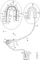
- An insertion apparatus 10 which is an endoscope apparatus as shown in FIG. 1 , is installed in, for example, an operation room or an examination room.
- the insertion apparatus 10 comprises an endoscope 20 for medical use and an insertion control apparatus 120 connected to the endoscope 20.
- the insertion apparatus 10 includes a display apparatus 140 (see FIG. 3B ) connected to the insertion control apparatus 120 and an input apparatus 160 connected to the insertion control apparatus 120.
- the insertion apparatus 10 includes a light source apparatus (not shown in the drawings) connected to the endoscope 20.
- the endoscope 20 is, for example, an example of an insertion apparatus that is inserted into a subject including a tube portion 300, which is the large intestine, for example.
- the endoscope 20 images the inside of the tube portion 300 using an imaging portion of an imaging unit (not shown in the drawings).
- the light source apparatus emits light to allow the imaging portion to perform imaging.
- the light is guided to an illumination portion (not shown in the drawings) of the illumination unit by a light guide member (not shown in the drawings) of the illumination unit provided inside the endoscope 20.
- the light is emitted from the illumination portion toward an outside as illumination light.
- An image taken by the imaging portion is output to an image control apparatus (not shown in the drawings) from the imaging portion via a signal line of the imaging unit provided inside the endoscope 20.
- the image control apparatus (not shown in the drawings) performs signal processing in such a manner that the image taken by the imaging portion is displayed on a display apparatus (not shown in the drawings).
- the insertion control apparatus 120 controls the bending stiffness of the insertion section 40 provided in the endoscope 20; however, the details will be described later.
- the display apparatus 140 displays the image taken by the imaging portion and image-processed by the image control apparatus.
- the input apparatus 160 is used to input various start instructions that will be described later.
- the endoscope 20 will be explained as a medical flexible endoscope as an example, but is not limited thereto.
- the endoscope 20 is only required to include a flexible insertion section 40 to be inserted into a subject, such as a flexible endoscope for industrial use, a catheter, or a treatment instrument.
- the subject is not limited to, for example, a human, and may be an animal or any other structural object.
- the endoscope 20 may be a front-viewing endoscope 20, or a side-viewing endoscope 20.
- the endoscope 20 includes an operation section 30 gripped by the operator and an insertion section 40 to be inserted into the subject.
- the operation section 30 is continuous with a proximal end portion of the insertion section 40.
- the operation section 30 includes a bending operation portion 31 used to operate a bendable portion 43 that will be described later, and a switch portion 33 used to operate a plurality of units such as the imaging unit.
- the operation section 30 further includes a universal cord 35, and is connected, via the universal cord 35, to the light source apparatus (not shown in the drawings), the image control apparatus (not shown in the drawings), and the insertion control apparatus 120.
- the insertion section 40 is tubular, elongated, and flexible.
- the insertion section 40 advances toward and retreats from the tube portion 300 inside the tube portion 300.
- the insertion section 40 is bendable along the tube portion 300.
- the insertion section 40 includes a distal rigid portion 41, the bendable portion 43, and a flexible tube 45 in this order from a distal end portion of the insertion section 40 toward a proximal end portion of the insertion section 40.
- a proximal end portion of the distal rigid portion 41 is coupled to a distal end portion of the bendable portion 43
- a proximal end portion of the bendable portion 43 is coupled to a distal end portion of the flexible tube 45
- a proximal end portion of the flexible tube 45 is coupled to the operation section 30.
- the imaging portion and the illumination portion are provided inside the distal rigid portion 41.
- the flexible tube 45 of the insertion section 40 is divided into a plurality of segments 50 arranged in a column shape along a longitudinal axis direction of the insertion section 40.
- the segments 50 may function as non-existent virtual regions, or may function as existent structures.
- the bending stiffness of each segment 50 can be independently changed under control of the stiffness control portion (hereinafter referred to as a control portion 127 (see FIG. 2 )), which will be described later, arranged in the insertion control apparatus 120.
- the bending stiffness of the flexible tube 45 may be partially changed by the bending stiffness of the segments 50 independently controlled by the insertion control apparatus 120.
- the segments 50 are obtained by dividing the flexible tube 45, but are not limited thereto, and the segments 50 may be obtained by dividing the insertion section 40. It is thereby possible to partially change the bending stiffness of the insertion section 40 based on the bending stiffness of each of the segments 50 independently controlled by the control portion 127.
- the insertion apparatus 10 includes one or more stiffness variable portions 51 that can be changed in stiffness.
- the stiffness variable portions 51 are incorporated into the respective segments 50.
- the stiffness variable portions 51 may be incorporated into all the segments 50, or may be incorporated into only some of the segments 50.
- the area at which the stiffness variable portion 51 is provided may function at least as the segment 50.
- One stiffness variable portion 51 may be integrally incorporated into a plurality of segments 50.
- the stiffness variable portions 51 may be arranged in a line along the longitudinal axis direction of the insertion section 40, or may be arranged in a plurality of lines.
- the stiffness variable portions 51 When the stiffness variable portions 51 are arranged in a plurality of lines, the stiffness variable portions 51 may be provided at the same position in such a manner that the stiffness variable portions 51 are adjacent to each other as viewed in the circumferential direction of the flexible tube 45, or may be provided so as to be shifted as viewed in the longitudinal axis direction of the insertion section 40.
- the stiffness variable portions 51 are only required to change the bending stiffness of the insertion section 40 in units of segments, according to a change in stiffness of the stiffness variable portions 51.
- the stiffness variable portion 51 is configured by, for example, an actuator including a coil pipe formed by a metal line and a conductive electroactive polymer artificial muscle (hereinafter referred to as EPAM) sealed inside the coil pipe.
- the central axis of the coil pipe is provided to match a central axis of the insertion section 40, or in parallel therewith.
- the coil pipe includes electrodes provided on both end portions of the coil pipe.
- the electrodes are connected to the insertion control apparatus 120 via a signal cable (not shown in the drawings) incorporated into the endoscope 20, and receive electric power supplied from the insertion control apparatus 120.
- a voltage is applied to the EPAM via the electrodes, the EPAM extends and contracts along the central axis of the coil pipe. However, the EPAM is restricted from extending and contracting by the coil pipe. Thereby, the stiffness of the stiffness variable portion 51 changes.
- the stiffness of the stiffness variable portion 51 increases as the value of the applied voltage increases.
- the bending stiffness of the segments 50 incorporating the stiffness variable portions 51 also changes in accordance therewith. Electric power is independently supplied to the respective electrodes.
- the stiffness variable portions 51 independently change in stiffness, and the segments 50 also independently change in bending stiffness.
- the stiffness variable portions 51 change the bending stiffness of the segments 50 according to the change in stiffness of the stiffness variable portions 51, and partially change the bending stiffness of the flexible tube 45 according to the change in bending stiffness of the segments 50.
- a shape memory alloy may be used, instead of the EPAM.
- the insertion apparatus 10 includes a detection unit 60 that detects state information of the insertion section 40 including at least the shape information of the insertion section 40.
- the detection unit 60 starts detection upon receiving start instructions (a detection start instruction and a calculation start instruction that will be described later) from the input apparatus 160, and constantly performs the detection.
- start instructions a detection start instruction and a calculation start instruction that will be described later
- the detection timing may be every predetermined passage of time, and is not particularly limited.
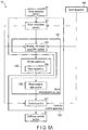
- the detection unit 60 includes a state detection portion 61 arranged inside the insertion section 40, as shown in FIG. 1 , and a state calculation portion 63 arranged in the insertion control apparatus 120, as shown in FIG. 2 .
- the state detection portion 61 detects state information of the insertion section 40 including shape information and twist information of the insertion section 40.
- the shape information of the insertion section 40 refers to, for example, the shape of the insertion section 40 as viewed in the longitudinal axis direction of the insertion section 40.
- the state detection portion 61 includes, for example, at least one of a coil, an output portion, an optical fiber sensor, a strain sensor, and an absorption member.
- the coil generates a magnetic field in response to the state of the insertion section 40, such as the shape of the insertion section 40.
- the output section outputs electromagnetic waves or ultrasound waves in response to the state of the insertion section 40.
- the optical fiber sensor can be changed in progress ratio of light in response to the state of the insertion section 40.
- the absorption member absorbs X-rays in response to the state of the insertion section 40.
- the state detection portion 61 constantly performs a detection (operation) after the detection start instruction output from the input apparatus 160 is input to the state detection portion 61.
- the state detection portion 61 is connected to the state calculation portion 63 by wire or by wireless, for example, and outputs the detection result detected by the state detection portion 61 to the state calculation portion 63.
- the state calculation portion 63 calculates state information of the insertion section 40 on the basis of the detection result of the state detection portion 61. As shown in FIG. 3C , assuming that, for example, bent portions in the tube portion 300 which is the subject are bent portions 301a and 301b, the bent portion 301a is located ahead of the bent portion 301b as viewed in the insertion direction of the insertion section 40. In the present embodiment, an explanation is made using two bent portions 301a and 301b; however, the number of the bent portions is not particularly limited thereto.
- the state calculation portion 63 is configured by, for example, an arithmetic circuit including a CPU, an ASIC, or the like.
- the state calculation portion 63 constantly performs a calculation (operation) after the calculation start instruction output from the input apparatus 160 is input to the state calculation portion 63.
- the state calculation portion 63 is connected to the display apparatus 140, and outputs a calculation result calculated by the state calculation portion 63 to the display apparatus 140.
- the display apparatus 140 displays the current state information of the insertion section 40 the inside of the tube portion 300, on the basis of the calculation result calculated by the state calculation portion 63.
- the display is performed in a three-dimensional manner, for example.
- the operator is capable of monitoring the shape of the insertion section 40 the inside of the tube portion 300 on the basis of the state information of the insertion section 40 displayed on the display apparatus 140.
- the state calculation portion 63 is connected to a bend determination portion 121 and the control portion 127, which will be described later, and outputs a calculation result calculated by the state calculation portion 63 to the bend determination portion 121 and the control portion 127.
- the insertion apparatus 10 includes the bend determination portion 121 arranged in the insertion control apparatus 120.
- the bend determination portion 121 is configured by, for example, a calculation circuit including a CPU, an ASIC, or the like.
- the bend determination portion 121 determines whether or not the bent parts 201a and 201b (see FIG. 3E ) are present in the insertion section 40, on the basis of the shape information of the insertion section 40 calculated by the state calculation portion 63.
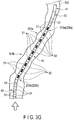
- the parts including the shaded stiffness variable portions 51 in FIG. 3E are the parts determined by the bend determination portion 121 as the bent parts 201a and 201b.
- the bend determination portion 121 starts a determination when a determination start instruction is input from the input apparatus 160, and constantly performs the determination.
- the determination timing may be every predetermined passage of time, and is not particularly limited.
- the bend determination portion 121 includes a bending information calculation portion 123 that calculates bending information of the insertion section 40 on the basis of the shape information of the insertion section 40, and a determination main portion 125 that determines whether or not the bent parts 201a and 201b are present on the basis of the bending information.
- the bending information represents at least one of a magnitude of the bend of the insertion section 40 and a direction of the bend of the insertion section 40.
- the magnitude of the bend of the insertion section 40 represents, for example, a radius of curvature or a curvature.
- the bending information represents a radius of curvature of the magnitude of the bend of the insertion section 40.
- the bending information includes, for example, a bend curve expressed by the solid or dotted lines shown in FIG. 3F , for example.
- the bend curve expresses a relationship between each position of the insertion section 40 and the radius of curvature of the insertion section 40.
- the radius of curvature is calculated on the basis of the positional information of the insertion section 40 obtained by the state detection portion 61.
- the positional information refers to positional information indicating detection data that is detected at, for example, at least three given positions.
- the bending information calculation portion 123 outputs the calculated radius of curvature to the determination main portion 125 and the control portion 127.
- the bending information calculation portion 123 may be included in the state calculation portion 63.
- the determination main portion 125 determines the bent parts 201a and 201b on the basis of the magnitude of the bend and a threshold value set in advance for the magnitude of the bend. As shown in FIG. 3F , for example, the determination main portion 125 compares the threshold value set in advance and the radius of curvature, and determines that the parts at which the radius of curvature has fallen below the threshold value are the bent parts 201a and 201b. The determination main portion 125 outputs a determination result of the determination main portion 125 to the control portion 127.
- the determination main portion 125 determines that the bent parts 201a and 201b are present, the determination main portion 125 outputs, to the control portion 127, the positional information of the bent parts 201a and 201b in the insertion section 40, along with the determination result. On the basis of the threshold value and the radius of curvature, the determination main portion 125 determines whether or not the bent parts 201a and 201b are parts that may be bent by buckling, for example, and whether or not a bend has been caused in the course of insertion.
- the bent parts 201a and 201b are parts of the insertion section 40 in the bend curve located below the threshold value, and are stiffness variable regions whose bending stiffness can be changed by the control portion 127, which will be described later.
- the bent parts 201a and 201b are parts of the insertion section 40 other than the substantially straight parts 203a and 203b (see FIGS. 3F and 3G ), which include a straight part (not shown in the drawings).
- the threshold value indicates the degree of the bend of the bent parts 201a and 201b.
- the threshold value is stored in advance in, for example, a storage portion (not shown in the drawings) and is suitably read by the determination main portion 125 from the storage portion.
- the threshold value may be input from, for example, the input apparatus 160 to the determination main portion 125.
- the threshold value may be suitably set in accordance with the tube portion 300.
- the threshold value suitably differs according to, for example, the patient.
- the insertion apparatus 10 includes the control portion 127 arranged in the insertion control apparatus 120.
- the control portion 127 is configured by, for example, an arithmetic circuit including a CPU, an ASIC, or the like.
- the control portion 127 is connected to the stiffness variable portions 51 via a signal cable (not shown in the drawings) incorporated into the endoscope 20 including the universal cord 35.
- the control portion 127 controls the stiffness of the stiffness variable portions 51 corresponding to the segments 50 arranged in the bent parts 201a and 201b to be a stiffness that makes the bent parts 201a and 201b substantially straight.
- the control portion 127 increases the stiffness of the stiffness variable portions 51 to a stiffness that makes the bent parts 201a and 201b substantially straight, to change the bent parts 201a and 201b to substantially straight parts 203a and 203b (see FIGS. 3F and 3G ).
- the control portion 127 increases the stiffness of the stiffness variable portions 51 to a stiffness that makes the bent parts 201a and 201b substantially straight, to change the passing parts 209a and 209b, which are parts passing through the bent portions 301a and 301b, from a bent state to a substantially straight state.
- the passing parts 209a and 209b correspond to the bent parts 201a and 201b.
- the stiffness of the stiffness variable portions 51 that are indicated in black in FIG. 3G is controlled, and the substantially straight parts 203a and 203b are generated.
- the stiffness variable portions 51 corresponding to the segments 50 refer to, for example, the stiffness variable portions 51 provided in the segments 50, namely, the stiffness variable portions 51 of the segments 50 whose bending stiffness can be changed.
- the stiffness that makes the bent parts 201a and 201b substantially straight refers to a stiffness that changes the bent parts 201a and 201b to the substantially straight parts 203a and 203b, and that keeps the substantially straight parts 203a and 203b in the substantially straight state without causing them to be bent, even when an external force is applied to the substantially straight parts 203a and 203b.
- the external force refers to a force applied to the substantially straight parts 203a and 203b from a given angle with respect to the central axis of, for example, the substantially straight parts 203a and 203b.
- the substantially straight stiffness is higher than a stiffness that is not controlled by the control portion 127.
- the bending stiffness of the substantially straight parts 203a and 203b is higher than the other parts in which the bending stiffness is not controlled.
- the substantially straight parts 203a and 203b function as high bending stiffness parts that are not bent and maintain the substantially straight state even if an external force is applied thereto.
- the other parts that are not controlled in bending stiffness function as low bending stiffness parts that can be passively bent upon receiving an external force.
- the substantially straight stiffness can be adjusted as desired according to the tube portion 300.
- the control portion 127 controls the stiffness of the stiffness variable portions 51 on the basis of the magnitude of the bend and the threshold value. As shown in FIG. 3F , for example, the control portion 127 controls the stiffness of the stiffness variable portions 51 to be a stiffness that makes the radius of curvature of each of the bent parts 201a and 201b exceed the threshold value. This stiffness indicates a substantially straight stiffness. The control portion 127 increases the stiffness of the stiffness variable portion 51 to a substantially straight stiffness until the radius of curvature of each of the bent parts 201a and 201b exceeds a threshold value.
- the control portion 127 constantly receives the radius of curvature of each of the bent parts 201a and 201b input from the bending information calculation portion 123, and controls the stiffness on the basis of the radius of curvature and the threshold value of each of the bent parts 201a and 201b.
- the control portion 127 suitably reads a threshold value from the storage portion (not shown in the drawings).
- the control portion 127 controls the stiffness of the stiffness variable portions 51 provided in the segments 50 arranged in all the bent parts 201a and 201b. That is, the control portion 127 uniformly changes the bent parts 201a and 201b to the substantially straight parts 203a and 203b. For example, the control portion 127 simultaneously starts controlling.
- the control portion 127 may control the stiffness of the stiffness variable portion 51 provided in the segment 50 that is arranged at the center of the bent part 201a as viewed in the longitudinal axis direction of the insertion section 40.
- control portion 127 may control the bent part 201a, for example, in such a manner that the stiffness of the stiffness variable portions 51 of the entire bent part 201a becomes equal.
- control portion 127 may set a difference in stiffness in the bent part 201a, for example, in such a manner that the stiffness of the stiffness variable portion 51 provided in the segment 50 arranged at the center of the bent part 201a as viewed in the longitudinal axis direction of the insertion section 40 becomes the highest, and that the stiffness of the stiffness variable portion 51 provided in the segment 50 arranged at an end portion of the bent part 201a as viewed in the longitudinal axis direction of the insertion section 40 becomes the lowest.
- the control portion 127 is not limited to one that controls only the stiffness of the stiffness variable portions 51 provided in the segments 50 arranged in the bent parts 201a and 201b.
- the control portion 127 may control the stiffness of the stiffness variable portion 51 corresponding to segments 50a located ahead of and behind the segments 50 arranged in the bent parts 201a and 201b to be a substantially straight stiffness.
- the control portion 127 may control the stiffness of the stiffness variable portion 51 provided in a desired segment 50 other than the segments 50 arranged in the bent part to be a desired stiffness, for example.
- the control portion 127 controls, as desired, the stiffness of the stiffness variable portion 51 corresponding to the segment 50 that has passed through a desired part in the tube portion 300 and has the stiffness controlled to be substantially straight.
- the desired part refers to, for example, substantially straight portions 303a and 303b.
- the control portion 127 decreases the substantially straight stiffness of the stiffness variable portion 51 in the substantially straight parts 203a and 203b to a desired stiffness. In this case, the stiffness of the shaded stiffness variable portions 51 in the substantially straight parts 203a and 203b in FIG. 3H is decreased by the control portion 127.
- the passage completion parts 211 which are substantially straight parts 203a and 203b that have completed passing through the bent portions 301a and 301b (substantially straight portions 303a and 303b), can be bent upon receiving an external force, and become bendable along the tube portion 300.
- the desired stiffness refers to, for example, the initial stiffness before the stiffness is changed.
- the initial stiffness refers to a stiffness that allows the insertion section 40 to be passively bent by, for example, an external force.
- the initial stiffness may be a stiffness that allows the insertion section 40 to be bent along the tube portion 300.
- the desired stiffness may be zero or any value lower than the substantially straight stiffness, and may be set to a desired value again.
- the control portion 127 may end control of the stiffness.
- the control portion 127 starts control upon receiving a control start instruction input from the input apparatus 160, and constantly performs the control.
- the control timing may be every predetermined passage of time, and is not particularly limited.
- the input apparatus 160 outputs to the detection unit 60 a detection start instruction and a calculation start instruction to start detection and calculation of the detection unit 60, outputs to the bend determination portion 121 a determination start instruction to start the determination of the bend determination portion 121, and outputs to the control portion 127 a control start instruction to start control of the control portion 127.
- the input apparatus 160 may output a detection start instruction, a calculation start instruction, a determination start instruction, and a control start instruction either simultaneously or individually.
- the input apparatus 160 performs this output before the insertion is performed, namely, before control of the control portion 127 is performed.
- the input apparatus 160 is, for example, a general input device, and is, for example, a pointing device such as a keyboard and a mouse, a tag reader, a button switch, a slider, and a dial.
- the control mode refers to, for example, control of only the stiffness of the stiffness variable portions 51 provided in the segments 50 arranged in the bent parts 201a and 201b, or control of the stiffness of the stiffness variable portions 51 provided in the segments 50 arranged in the bent parts 201a and 201b and the segments 50 located ahead of and behind these segments 50.
- the insertion section 40 is inserted into the tube portion 300 for insertion toward the deep portion, as shown in FIG. 3A .
- the state detection portion 61 detects the state information of the insertion section 40 in real time.
- the detection result detected by the state detection portion 61 is output to the state calculation portion 63 in real time.
- the state calculation portion 63 calculates state information of the insertion section 40 in real time, on the basis of the detection result of the state detection portion 61.
- the state calculation portion 63 outputs a calculation result calculated by the state calculation portion 63 to the display apparatus 140, the bend determination portion 121, and the control portion 127.
- the display apparatus 140 displays the current state of the insertion section 40 inside of the tube portion 300 in real time, on the basis of the calculation result calculated by the state calculation portion 63.
- the operator monitors the shape of the insertion section 40 inside of the tube portion 300 on the basis of the state of the insertion section 40 displayed on the display apparatus 140.
- the insertion section 40 passes through the bent portions 301a and 301b, as shown in FIG. 3C .
- the display apparatus 140 displays, using the state detection portion 61 and the state calculation portion 63, the shape of the insertion section 40 that is bent in accordance with the tube portion 300 and the bent portions 301a and 301b, and the insertion section 40 that passes through the bent portions 301a and 301b while bending. This situation is monitored by the operator.
- the operator For insertion of the insertion section 40 toward a deep portion under a situation where the insertion section 40 is passing through the bent portions 301a and 301b, the operator grips the proximal end portion of the insertion section 40 exposed to the outside from the tube portion 300, and pushes the insertion section 40 forward from the gripped part.
- the passing parts 209a and 209b passing through the bent portions 301a and 301b may prevent the hand side force that pushes the insertion section 40 forward from being easily transmitted to the distal end portion of the insertion section 40 from the gripped part. Thereby, buckling may occur in the passing parts 209a and 209b, reducing the insertability of the insertion section 40 into a deep portion.
- the input apparatus 160 outputs a determination start instruction to the bend determination portion 121, and outputs a control start instruction to the control portion 127.
- the bend determination portion 121 determines whether or not the bent parts 201a and 201b are present in the insertion section 40 in real time, on the basis of the shape information of the insertion section 40. Specifically, the bending information calculation portion 123 calculates a radius of curvature, which is bending information of the insertion section 40, on the basis of the shape information of the insertion section 40 in real time, and outputs the calculated radius of curvature to the determination main portion 125 and the control portion 127. As shown in FIGS.
- the determination main portion 125 compares a threshold value set in advance and a radius of curvature, determines whether or not the radius of curvature has fallen below the threshold value, and determines that the parts at which the radius of curvature has fallen below the threshold value are bent parts 201a and 201b. Let us assume that the determination main portion 125 determines that the bent parts 201a and 201b are present in the insertion section 40. The determination main portion 125 outputs a determination result including positional information of the bent parts 201a and 201b in the insertion section 40 to the control portion 127.
- the control portion 127 calculates a part at which the bending stiffness should be changed in the insertion section 40, on the basis of the positional information of the bent parts 201a and 201b in the determination result. As shown in FIGS. 3F and 3G , the control portion 127 controls, in real time, the stiffness of the stiffness variable portions 51 provided in the segments 50 arranged in the bent parts 201a and 201b to be a substantially straight stiffness. For example, the control portion 127 controls the stiffness of the stiffness variable portions 51 to be a stiffness that makes the radius of curvature exceed the threshold value.
- the stiffness of the stiffness variable portions 51 increases to a substantially straight stiffness
- the bent parts 201a and 201b change to substantially straight parts 203a and 203b, as shown in FIGS. 3F and 3G .
- the bent portions 301a and 301b change to substantially straight portions 303a and 303b.
- the control portion 127 changes the bent parts 201a and 201b to substantially straight parts 203a and 203b by controlling the stiffness of the stiffness variable portions 51, and changes the bent portions 301a and 301b to substantially straight portions 303a and 303b based on the substantially straight parts 203a and 203b.
- the control portion 127 relieves the bent portions 301a and 301b.
- the control portion 127 changes the state of the bent portions 301a and 301b as well, in accordance with the change in state of the passing parts 209a and 209b.
- the hand side force is efficiently transmitted from the gripped part to the distal end portion of the insertion section 40, by the substantially straight parts 203a and 203b and the substantially straight portions 303a and 303b.
- the substantially straight parts 203a and 203b are configured in such a manner that the substantially straight portions 303a and 303b are easily inserted toward a deep portion. That is, the insertion section 40 is easily advanced forward, thus improving the insertability of the insertion section 40.
- the substantially straight parts 203a and 203b have a high bending stiffness, the hand side force is efficiently transmitted to the distal end portion of the insertion section from the gripped part. This prevents occurrence of buckling, and improves the insertability of the insertion section 40 into a deep portion.
- the stiffness of the stiffness variable portion may not increase and the bent parts 201a and 201b attempt to pass through the bent portions 301a and 301b in a bent state.
- the bent parts 201a and 201b may prevent the hand side force from being easily transmitted to the distal end portion of the insertion section, buckling may occur in the bent parts 201a and 201b. Even when the passing parts 209a and 209b are substantially straight parts, buckling may occur when the bending stiffness of the substantially straight parts is low.
- the bent portions 301a and 301b cannot be changed to substantially straight portions, the bent portions 301a and 301b remain in a bent state, and the substantially straight parts having a low bending stiffness may not endure the pressure of the bent portions 301a and 301b and may be bent.
- the bent parts 201a and 201b reliably change to the substantially straight parts 203a and 203b
- the bent portions 301a and 301b reliably change to the substantially straight portions 303a and 303b based on the substantially straight parts 203a and 203b
- the bending stiffness of the substantially straight parts 203a and 203b is increased by the change in stiffness of the stiffness variable portions 51.
- This prevents a bend of the substantially straight parts 203a and 203b the hand side force is efficiently transmitted from the gripped part to the distal end portion of the insertion section 40, and the insertion section 40 is easily inserted toward a deep portion, thus improving the insertability of the insertion section 40.
- the hand side force is efficiently transmitted from the gripped part to the distal end portion of the insertion section 40, occurrence of buckling is prevented, and the insertability of the insertion section 40 into a deep portion is improved.
- the tube portion 300 is the large intestine, for example, and when the insertion section 40 is passing through the sigmoid colon, which is represented by the bent portions 301a and 301b, the passing parts 209a and 209b passing through the sigmoid colon in the insertion section 40 are the bent parts 201a and 201b.
- the bent parts 201a and 201b change to the substantially straight parts 203a and 203b
- the sigmoid colon (bent portions 301a and 301b) change to the substantially straight portions 303a and 303b by the substantially straight parts 203a and 203b.
- the bending stiffness of the substantially straight parts 203a and 203b is increased by the change in stiffness of the stiffness variable portions 51. This prevents a bend of the substantially straight parts 203a and 203b, the hand side force is efficiently transmitted from the gripped part to the distal end portion of the insertion section 40, and thereby occurrence of buckling is prevented.
- the insertion section 40 is easily inserted toward the transverse colon located in a deep portion of the large intestine than the sigmoid colon, and thereby the insertability of the insertion section 40 is improved.
- the bent parts corresponding to the sigmoid colon and the transverse colon are respectively changed to substantially straight parts, and the sigmoid colon and the transverse colon are changed to substantially straight portions by the substantially straight parts. This facilitates insertion toward the ascending colon located in a deep portion of the large intestine than the transverse colon, and improves the insertability of the insertion section 40.
- the sigmoid colon and the transverse colon, for example, of the large intestine are not fixed within the abdomen, and are easily moved inside the abdomen.
- insertion into the flexible and easily bendable large intestine, which is moved by an insertion operation of the insertion section 40, is not easy.
- the insertion section 40 is easily inserted toward a deep portion, as described above.
- the insertability is improved even if the state of the tube portion 300 changes in accordance with insertion of the insertion section 40.
- the control portion 127 determines the passage on the basis of the calculation result (shape information of the insertion section 40) of the state calculation portion 63. As shown by the shading in FIG. 3H , the control portion 127 decreases the substantially straight stiffness of the stiffness variable portions 51 provided in the segments 50 that are arranged in the passage completion parts 211, which are substantially straight parts 203a and 203b that have completed passing through the substantially straight portions 303a and 303b and have a substantially straight stiffness, to a desired stiffness. For example, the control portion 127 resets the controlled stiffness of the stiffness variable portions 51 to the initial stiffness.
- the passage completion part 211 is relieved from the substantially straight state, returns to the low bending stiffness part, and becomes bendable upon receiving an external force. Accordingly, the insertion section 40 can be bent along the tube portion 300. Let us assume that the operator monitors the state of the insertion section 40 via the display apparatus 140. Under such a situation, the operator may operate the input apparatus 160, and stop outputting various start instructions from the input apparatus 160. Thereby, the passage completion part 211 is relieved from the substantially straight state, returns to the low bending stiffness part, and becomes bendable upon receiving an external force.
- the above-described operations of the bend determination portion 121 and the control portion 127 are repeated. Accordingly, as the insertion section 40 is inserted, the critical part (position) of the insertion section 40 that changes in bending stiffness may be shifted backward; however, the control portion 127 changes (switches) the stiffness variable portion 51 that changes in stiffness, in such a manner that the portion of the insertion section 40 that changes in bending stiffness does not relatively change with respect to the bent portions 301a and 301b.
- the control portion 127 controls the stiffness variable portions 51 in such a manner that the stiffness variable portion 51 that changes in stiffness is shifted from the stiffness variable portion 51 that is passing through the bent portions 301a and 301b and the stiffness variable portion 51 that is to pass through the bent portions 301a and 301b.
- the bending stiffness of the insertion section 40 in the passing parts 209a and 209b that are passing through the bent portions 301a and 301b constantly change.
- the part is only required to include at least one segment 50.
- the part that changes in bending stiffness does not relatively change with respect to the bent portions 301a and 301b, and the bending stiffness of the insertion section 40 in the passing parts 209a and 209b that pass through the bent portions 301a and 301b constantly change.
- control portion 127 may maintain the substantially straight stiffness of the stiffness variable portions 51 in the substantially straight parts 203a and 203b.
- the bent parts 201a and 201b corresponding to the shape of the bent portions 301a and 301b are detected and determined, and the stiffness of the stiffness variable portions 51 is controlled in such a manner that the bent parts 201a and 201b change to a substantially straight state. Accordingly, in the present embodiment, the bent parts 201a and 201b can be changed to the substantially straight parts 203a and 203b, and the hand side force can be efficiently transmitted from the gripped part to the distal end portion of the insertion section 40 by the increase in bending stiffness of the substantially straight parts 203a and 203b, thus improving the insertability of the insertion section 40 into a deep portion.
- the bending stiffness of the substantially straight parts 203a and 203b can be increased and the hand side force can be efficiently transmitted to the distal end portion of the insertion section 40 from the gripped part, it is possible to prevent occurrence of buckling and to improve insertability of the insertion section 40 into a deep portion.
- since the occurrence of buckling can be prevented, it is possible to insert the insertion section 40 into a patient in a less-invasive manner.
- the insertability of the insertion section 40 can be improved, it is possible to reduce the burden on the operator who operates the insertion apparatus 10.
- the bent parts 201a and 201b are uniformly changed to a substantially straight state. It is thus possible to eliminate hard-to-acquire procedures or complicated procedures for changing the bent parts 201a and 201b into a substantially straight state. Examples of such procedures include a procedure of changing the buckling part to substantially straight parts 203a and 203b by retreating the insertion section 40 by pulling, or the operator's or assistant's manual pressure that pushes the buckling part over the abdomen.
- bent parts 201a and 201b it is possible to change the bent parts 201a and 201b to substantially straight parts 203a and 203b with ease and safety, without burdening the operator.
- the determination main portion 125 determines the presence of the bent parts 201a and 201b on the basis of the bending information. Accordingly, the bent parts 201a and 201b can be determined with high precision. In the present embodiment, the determination main portion 125 determines that the parts at which the radius of curvature is below the threshold value are bent parts 201a and 201b. Accordingly, the load on the control portion 127 that controls the stiffness of the stiffness variable portion 51 can be reduced. In the present embodiment, the control portion 127 controls the stiffness of the stiffness variable portion 51 to be a stiffness that makes the radius of curvature exceed the threshold value. Accordingly, when the stiffness of the stiffness variable portion 51 is changed, the stiffness can be reliably defined.
- the passage completion parts 211 when the substantially straight parts 203a and 203b have completed passing through the substantially straight portions 303a and 303b, the passage completion parts 211, which are substantially straight parts 203a and 203b, are relieved from the substantially straight state and return to the low bending stiffness parts. This allows the passage completion parts 211 to be bent along the tube portion 300, thus improving the insertability.
- control portion 127 continues changing the stiffness of the stiffness variable portions 51 in real time; however, the configuration is not limited thereto.
- the control portion 127 may change the stiffness of the stiffness variable portions 51 only at a timing when the control start instruction is input.
- the curvature is the reciprocal of the radius of curvature. Accordingly, the determination main portion 125 compares the threshold value set in advance and the curvature, and determines that the part at which the curvature is above a threshold value is the bent parts 201a and 201b. The control portion 127 controls the stiffness of the stiffness variable portions 51 to be a stiffness that makes the curvature of each of the bent parts 201a and 201b fall below the threshold value.
- a first modification of the first embodiment will be explained with reference to FIGS. 4A , 4B , and 4C .
- the present modification only the features different from those of the first embodiment will be described.
- Bending information of the present modification represents a radius of curvature that is a magnitude of a bend of an insertion section 40.
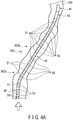
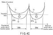
- An input apparatus 160 outputs a comparison start instruction, which is an instruction to start comparison, to a determination main portion 125, at a time T1 (see FIGS. 4A and 4C ), which is a start time of a desired period of time.
- the input apparatus 160 outputs a length of the desired period of time to the determination main portion 125.
- the desired period of time may be set in advance.
- the determination main portion 125 determines, on the basis of the threshold value set in advance and a change amount of the radius of curvature in the desired period of time, that the parts at which the radius of curvature has fallen below the threshold value after passage of the desired period of time are the bent parts 201a and 201b.
- the control portion 127 controls the stiffness of the stiffness variable portions 51 until the radius of curvature exceeds a threshold value.
- the operator operates an input apparatus 160, and the input apparatus 160 outputs a comparison start instruction to the determination main portion 125.
- the radius of curvature is above the threshold value at the time T1.
- the determination main portion 125 compares the radius of curvature at the time T2 and the threshold value. When the radius of curvature at the time T2 has fallen below the threshold value, the determination main portion 125 determines that the parts at which the radius of curvature is below the threshold value are bent parts 201a and 201b.
- the control portion 127 controls the stiffness of the stiffness variable portion 51 at the bent parts 201a and 201b to a substantially straight stiffness until the radius of curvature at the time T2 exceeds the threshold value.
- the parts at which the radius of curvature is below the threshold value are constantly determined as bent parts 201a and 201b, and are changed in stiffness.
- the bent parts 201a and 201b are determined on the basis of the change amount of the radius of curvature in a desired period of time, it is possible to reduce the load on the control portion 127 that controls the stiffness of the stiffness variable portions 51.
- the radius of curvature is used in the present modification; however, the curvature may be used instead.
- the curvature is the reciprocal of the radius of curvature. Accordingly, the determination main portion 125 determines, on the basis of the threshold value set in advance and the change amount of the curvature in the desired period of time, that the parts at which the curvature after passage of the desired period of time exceeds the threshold value are bent parts 201a and 201b.
- the control portion 127 controls the stiffness of the stiffness variable portions 51 until the curvature falls below the threshold value.
- FIGS. 5A, 5B , and 5C A second modification of the first embodiment will be explained with reference to FIGS. 5A, 5B , and 5C .
- the present modification only the features different from those of the first embodiment will be described.
- Bending information of the present modification represents a radius of curvature that is a magnitude of a bend of an insertion section 40.
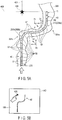
- FIG. 5A the intersection of a first extension line 401 of a central axis of a part of the insertion section 40 located at an entrance of a tube portion 300 of a subject and a second extension line 403 of an orthogonal axis that is orthogonal to the central axis of a distal end portion of the insertion section 40 inserted into the tube portion 300 of the subject is defined as an origin point 405.
- the display apparatus 140 displays the current state information of the insertion section 40 inside of the tube portion 300 on the basis of the detection result of the detection unit 60, as shown in FIG. 5B .
- the insertion apparatus 10 includes an input portion 180 that is arranged in the display apparatus 140, and inputs the origin point 405 on the basis of the state information of the insertion section 40 displayed on the display apparatus 140.
- the input portion 180 is, for example, a touch panel arranged on the display apparatus 140. Accordingly, the origin point 405 is input by the operator's operation on the input portion 180, in a state in which the operator is visually observing the current state information of the insertion section 40 inside of the tube portion 300 displayed on the display apparatus 140.
- the positional information on the input origin point 405 is output to the determination main portion 125.
- the origin point 405 is input to the determination main portion 125 on the basis of the shape information of the insertion section 40.
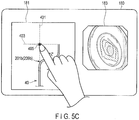
- the input portion 180 may be a portable terminal such as a tablet provided separately from the display apparatus 140, as shown in FIG. 5C .
- the input portion 180 includes a first display portion 181 and a second display portion 183, which synchronously display display information displayed on the display apparatus 140.
- the first display portion 181 displays the current state information of the insertion section 40 inside of the tube portion 300, for example.
- the second display portion 183 displays an image taken by, for example, an imaging portion.
- the input portion 180 is connected to the insertion control apparatus 120 by wireless, for example.
- the input portion 180 is, for example, a general input device, and may be, for example, a pointing device such as a keyboard, a mouse, etc.
- the determination main portion 125 compares the threshold value set in advance and the radius of curvature, and determines that the parts at which the radius of curvature is below the threshold value are the bent parts 201a and 201b, as in the first embodiment. Furthermore, the determination main portion 125 determines that the part at which the radius of curvature has a central position P2 (see FIG. 5A ), that is located on the side opposite to the origin point 405 with the insertion section 40 interposed therebetween, is the bent part 201b generated by buckling. For example, when the insertion section 40 passes through the sigmoid colon, as shown in FIG.
- the bent part 201b in the sigmoid colon is a part where buckling may occur, and needs to be increased in bending stiffness.
- the determination main portion 125 determines that the passing part 209b that passes through the sigmoid colon is the bent part 201b.
- the determination main portion 125 determines that the part on the side of the origin point 405, e.g., the part at which the radius of curvature has a central position P1 between the origin point 405 and the insertion section 40, is the bending part 215 generated in the course of insertion.
- the bending part 215 is the part at which the insertion section 40 is bent toward the inside of the lumen in the course of insertion. Accordingly, the bending stiffness of the bending part 215 does not need to be increased.
- the central position P1 is located on the side of the origin point 405, e.g. , between the origin point 405 and the insertion section 40, and the determination main portion 125 determines that the passing part 209a that passes through the descending colon is the bending part 215.
- the control portion 127 controls only the stiffness of the stiffness variable portion 51 in the bent part 201b to be a stiffness that makes the radius of curvature exceed the threshold value.
- the bending information may represent the direction of the bend of the insertion section 40.
- the determination main portion 125 determines that the periphery of the part at which the direction of the bend is toward the origin point 405 is a bent part.
- the control portion 127 controls only the stiffness of the stiffness variable portions 51 in the bent part in such a manner that most of the directions of the bends in the bent part become the same direction.
- the radius of curvature is used in the present modification; however, the curvature may be used instead.
- the curvature is the reciprocal of the radius of curvature. Accordingly, the determination main portion 125 determines that the part at which the curvature has a central position P2 (see FIG. 5A ), located on the side opposite to the origin point 405 with the insertion section 40 interposed therebetween, is the bent part 201b generated by buckling.
- the control portion 127 controls only the stiffness of the stiffness variable portion 51 in the bent part 201b to be a stiffness that makes the curvature fall below the threshold value.
- a third modification of the first embodiment will be explained with reference to FIGS. 6A , 6B, and 6C .
- the present modification only the features different from those of the first embodiment will be described.
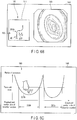
- the display apparatus 140 includes a first display portion 141 that displays the current state information of the insertion section 40 inside of the tube portion 300, and a second display portion 143 that displays an image taken by the imaging portion.
- the display apparatus 140 may display bending information and a threshold value, as shown in FIG. 6C .
- the display apparatus 140 is only required to display at least one of the current state information and bending information of the insertion section 40 inside the tube portion 300, on the basis of the detection result of the detection unit 60 and the calculation result of the bending information calculation portion 123.
- the insertion apparatus 10 includes an input portion 190 that inputs a designated part 217 based on at least one of the state information and bending information of the insertion section 40 displayed on the display apparatus 140.
- the input portion 190 is, for example, a touch panel arranged on the display apparatus 140.
- the input portion 190 may be a portable terminal such as a tablet provided separately from the display apparatus 140, as in the input portion 180.
- the input portion 190 is, for example, a general input device, and may be, for example, a pointing device such as a keyboard and a mouse.
- the designated part 217 is input to the determination main portion 125 by the operator's operation on the input portion 190, for example, in a state in which the operator is visually observing at least one of the current state information and bending information of the insertion section 40 inside of the tube portion 300 displayed on the display apparatus 140.
- the designated part 217 may be a position or a frame.
- the determination main portion 125 determines whether or not the designated part 217 input from the input portion 180 is the bent part 201b, on the basis of one of the state information and the bending information displayed on the display apparatus 140.
- the determination main portion 125 compares the radius of curvature of the designated part 217 and the threshold value, and determines that the designated part 217 is the bent part 201b when the radius of curvature has fallen below the threshold value.
- the control portion 127 performs control in a manner similar to the first embodiment.
- the operator visually observes at least one of the state information and the bending information of the insertion section 40 displayed on the display apparatus 140, and the operator selects a bent part 201b via the designated part 217. It is thus possible to select a part at which the bending stiffness is to be changed, thus improving the insertion efficiency of the insertion section 40.
Landscapes
- Health & Medical Sciences (AREA)
- Life Sciences & Earth Sciences (AREA)
- Surgery (AREA)
- Engineering & Computer Science (AREA)
- Biomedical Technology (AREA)
- Molecular Biology (AREA)
- Pathology (AREA)
- Radiology & Medical Imaging (AREA)
- Nuclear Medicine, Radiotherapy & Molecular Imaging (AREA)
- Biophysics (AREA)
- Physics & Mathematics (AREA)
- Heart & Thoracic Surgery (AREA)
- Medical Informatics (AREA)
- Optics & Photonics (AREA)
- Animal Behavior & Ethology (AREA)
- General Health & Medical Sciences (AREA)
- Public Health (AREA)
- Veterinary Medicine (AREA)
- Signal Processing (AREA)
- Endoscopes (AREA)
- Instruments For Viewing The Inside Of Hollow Bodies (AREA)
- Gastroenterology & Hepatology (AREA)
Abstract
Description
- The present invention relates to a flexible tube insertion apparatus.
- When a flexible, elongated insertion section is pushed forward into the inside of the large intestine (tube portion), the operator pushes the insertion section forward while gripping a proximal end portion of the insertion section exposed to the outside from the anus. Normally, the sigmoid colon, the transverse colon, and the like are not fixed within the abdomen, and are easily moved inside the abdomen. In an intestinal tract that is easily bent and moved by a push operation of the insertion section, the hand side force that pushes the insertion section forward may not be easily transmitted to a distal end portion of the insertion section. This is because the insertion section may be flexed in a direction different from the direction in which the insertion section is pushed forward, causing buckling that bends the insertion section in an unintended direction, for example. Such buckling prevents the hand side force from being easily transmitted to the distal end, and the distal end portion of the insertion section is prevented from being inserted toward (advancing toward) a deep portion, namely, the insertability is reduced. The deep portion refers to a position ahead of the current position in the insertion direction.
- To allow the hand side force to be easily transmitted to the distal end side of the insertion section, the operator has been using various procedures to make a buckling part of the insertion section in which buckling occurs substantially straight. As an example of such procedures, the operator relieves the flexure by a pull-back operation and a twist of the insertion section that has been flexed by the buckling, to change the buckling part to be substantially straight. Alternatively, as another example of such procedures, the operator or assistant applies a manual pressure by pressing the buckling part of the insertion section over the abdomen, to maintain the buckling part in a substantially straight shape.
- However, for cases where buckling cannot be avoided merely by the operator's procedures, examples of methods include a first method that uniformly increases the bending stiffness of the insertion section, and a second method that uses an overtube. Thereby, the insertion section maintains a substantially straight state and the hand side force is easily transmitted to the distal end side of the insertion section, allowing the insertion section to be inserted toward a deep portion.
- However, since the first method uniformly increases the bending stiffness of the insertion section, the bending stiffness of the insertion section cannot be changed according to the bending state of the entire length of the large intestine. Accordingly, the large intestine may be extended excessively in a large intestine part at which the insertion section should be advanced with a low bending stiffness, causing distress to the patient. That is, the first method is inconvenient for insertion into a deep portion.
- In the second method, the outer diameter of the insertion section increases, causing an increase in the patient's distress. Also, the operator needs to operate the overtube according to a push operation of the insertion section or a pull operation of the insertion section. This decreases the operability.
- On the other hand, Patent Literature 1, for example, discloses a flexible, elongated insertion section that is divided into a plurality of segments arranged in a column shape along the axial direction and having different bending stiffnesses. According thereto, the patient's distress is reduced, and the insertability of the insertion section into a deep portion is improved.
- Patent Literature 2, for example, discloses an endoscope that changes the bending stiffness of an insertion section by suitably changing the diameter of the insertion section. According thereto, the sigmoid colon or the transverse colon can be advantageously shortened or straightened.
-
- Patent Literature 1: Jpn. Pat. Appln. KOKOKU Publication No.
61-37931 - Patent Literature 2: Japanese Patent No.
4009519 - Patent Literature 1 and 2 does not disclose suitably changing the bending stiffness at a suitable location of an insertion section according to the actual bent state of the large intestine. The large intestine includes a plurality of bent portions, and there are cases where a part of the insertion section that has been changed in bending stiffness may be appropriate for a first bent portion of the large intestine, but may be inappropriate for a second bent portion of the large intestine.
- In such a case, the insertion section cannot cope with various bent portions, and insertion into (advancement toward) a deep portion of the large intestine becomes difficult. If the hand side force is transmitted to the insertion section under such a situation, buckling may occur, causing further reduction in the insertability into a deep portion.
- The present invention has been made in consideration of the above circumstances, and it is an object of the invention to provide a flexible tube insertion apparatus capable of improving insertability into a deep portion of the tube portion.
- A flexible tube insertion apparatus according to an embodiment of the present invention includes an insertion section that is divided into a plurality of segments arranged in a column shape along a longitudinal axis direction and that is inserted into a subject; one or more stiffness variable portions configured to change a bending stiffness of the insertion section in units of the segments; a detection unit that detects state information of the insertion section including at least shape information of the insertion section; a bend determination portion that determines, based on the shape information, whether or not a bent part is present in the insertion section; and a control portion that controls a stiffness of the stiffness variable portion corresponding to the segment arranged in the bent part to be a stiffness that makes the bent part substantially straight, when the bend determination portion determines that the bent part is present in the insertion section.
- According to the present invention, it is possible to provide a flexible tube insertion apparatus capable of improving the insertability into a deep portion of a tube portion.
-
-
FIG. 1 is a schematic diagram of a flexible tube insertion apparatus according to a first embodiment of the present invention. -
FIG. 2 is a diagram illustrating a relationship between a detection unit, a bend determination portion, a control portion, stiffness variable portions, a display apparatus, and an input apparatus. -
FIG. 3A is a diagram showing a state in which the insertion section is inserted into a tube portion for insertion toward a deep portion. -
FIG. 3B is a diagram of the insertion section displayed on a display apparatus in a state of being inserted into a tube portion for insertion toward a deep portion. -
FIG. 3C is a diagram showing a state in which the insertion section is passing through bent portions of the tube portion. -
FIG. 3D is a diagram of the insertion section displayed on the display apparatus in a state of passing through the bent portions of the tube portion. -
FIG. 3E is a diagram showing a state in which the bend determination portion determines that bent parts are present in the insertion section. -
FIG. 3F is a diagram showing a state in which a stiffness of stiffness variable portions corresponding to segments arranged in the bent parts is controlled to be a substantially straight stiffness. -
FIG. 3G is a diagram showing a state in which the bent parts have been changed to substantially straight parts based on the substantially straight stiffness. -
FIG. 3H is a diagram showing a state in which the stiffness of the stiffness variable portions is reset to an initial stiffness, and the insertion section is inserted toward a deep portion. -
FIG. 3I is a diagram showing control of the stiffness of the stiffness variable portions corresponding to segments located ahead of and behind the segments arranged in the bent parts. -
FIG. 4A is a diagram showing a state in which the insertion section is inserted into a tube portion for insertion toward a deep portion at a time T1, according to a first modification of the first embodiment. -
FIG. 4B is a diagram showing a state in which the insertion section is inserted into a tube portion for insertion toward a deep portion at a time T2 later than the time T1. -
FIG. 4C is a diagram showing a state in which a change amount of a radius of curvature of the bent portions from the time T1 to the time T2 has fallen below a threshold value. -
FIG. 5A is a diagram showing a state in which the insertion section is passing through the bent portion of the tube portion, according to a second modification of the first embodiment. -
FIG. 5B is a diagram showing an input operation of an origin point from an input portion arranged in the display apparatus, according to the second modification of the first embodiment. -
FIG. 5C is a diagram showing an input operation of an origin point from an input portion provided separately from the display apparatus, according to the second modification of the first embodiment. -
FIG. 6A is a diagram illustrating a relationship between a detection unit, a bend determination portion, a control portion, a stiffness variable portion, a display apparatus, and an input apparatus, according to a third modification of the first embodiment. -
FIG. 6B is a diagram showing an example of an input operation of a designated part from the input portion arranged in the display apparatus. -
FIG. 6C is a diagram showing an example of an input operation of a designated part from the input portion arranged in the display apparatus. - Hereinafter, embodiments of the present invention will be explained in detail with reference to the accompanying drawings. In
FIG. 1 , illustration of astate calculation portion 63 is omitted. Likewise, in some of the drawings, illustration of some members is omitted for clarification of the illustration. The deep portion refers to a position ahead of the current position as viewed in the insertion direction of aninsertion section 40. - An explanation will now be given of the first embodiment, with reference to the accompanying drawings.
- An
insertion apparatus 10, which is an endoscope apparatus as shown inFIG. 1 , is installed in, for example, an operation room or an examination room. Theinsertion apparatus 10 comprises anendoscope 20 for medical use and aninsertion control apparatus 120 connected to theendoscope 20. Theinsertion apparatus 10 includes a display apparatus 140 (seeFIG. 3B ) connected to theinsertion control apparatus 120 and aninput apparatus 160 connected to theinsertion control apparatus 120. Theinsertion apparatus 10 includes a light source apparatus (not shown in the drawings) connected to theendoscope 20. - The
endoscope 20 is, for example, an example of an insertion apparatus that is inserted into a subject including atube portion 300, which is the large intestine, for example. Theendoscope 20 images the inside of thetube portion 300 using an imaging portion of an imaging unit (not shown in the drawings). - The light source apparatus (not shown in the drawings) emits light to allow the imaging portion to perform imaging. The light is guided to an illumination portion (not shown in the drawings) of the illumination unit by a light guide member (not shown in the drawings) of the illumination unit provided inside the
endoscope 20. The light is emitted from the illumination portion toward an outside as illumination light. An image taken by the imaging portion is output to an image control apparatus (not shown in the drawings) from the imaging portion via a signal line of the imaging unit provided inside theendoscope 20. - The image control apparatus (not shown in the drawings) performs signal processing in such a manner that the image taken by the imaging portion is displayed on a display apparatus (not shown in the drawings).
- The
insertion control apparatus 120 controls the bending stiffness of theinsertion section 40 provided in theendoscope 20; however, the details will be described later. - The
display apparatus 140 displays the image taken by the imaging portion and image-processed by the image control apparatus. - The
input apparatus 160 is used to input various start instructions that will be described later. - The
endoscope 20 will be explained as a medical flexible endoscope as an example, but is not limited thereto. Theendoscope 20 is only required to include aflexible insertion section 40 to be inserted into a subject, such as a flexible endoscope for industrial use, a catheter, or a treatment instrument. The subject is not limited to, for example, a human, and may be an animal or any other structural object. Theendoscope 20 may be a front-viewingendoscope 20, or a side-viewingendoscope 20. - The
endoscope 20 includes anoperation section 30 gripped by the operator and aninsertion section 40 to be inserted into the subject. - The
operation section 30 is continuous with a proximal end portion of theinsertion section 40. Theoperation section 30 includes abending operation portion 31 used to operate abendable portion 43 that will be described later, and aswitch portion 33 used to operate a plurality of units such as the imaging unit. Theoperation section 30 further includes auniversal cord 35, and is connected, via theuniversal cord 35, to the light source apparatus (not shown in the drawings), the image control apparatus (not shown in the drawings), and theinsertion control apparatus 120. - The
insertion section 40 is tubular, elongated, and flexible. Theinsertion section 40 advances toward and retreats from thetube portion 300 inside thetube portion 300. Theinsertion section 40 is bendable along thetube portion 300. Theinsertion section 40 includes a distalrigid portion 41, thebendable portion 43, and aflexible tube 45 in this order from a distal end portion of theinsertion section 40 toward a proximal end portion of theinsertion section 40. A proximal end portion of the distalrigid portion 41 is coupled to a distal end portion of thebendable portion 43, a proximal end portion of thebendable portion 43 is coupled to a distal end portion of theflexible tube 45, and a proximal end portion of theflexible tube 45 is coupled to theoperation section 30. The imaging portion and the illumination portion are provided inside the distalrigid portion 41. - The
flexible tube 45 of theinsertion section 40 is divided into a plurality ofsegments 50 arranged in a column shape along a longitudinal axis direction of theinsertion section 40. Thesegments 50 may function as non-existent virtual regions, or may function as existent structures. - The bending stiffness of each
segment 50 can be independently changed under control of the stiffness control portion (hereinafter referred to as a control portion 127 (seeFIG. 2 )), which will be described later, arranged in theinsertion control apparatus 120. The bending stiffness of theflexible tube 45 may be partially changed by the bending stiffness of thesegments 50 independently controlled by theinsertion control apparatus 120. - The
segments 50 are obtained by dividing theflexible tube 45, but are not limited thereto, and thesegments 50 may be obtained by dividing theinsertion section 40. It is thereby possible to partially change the bending stiffness of theinsertion section 40 based on the bending stiffness of each of thesegments 50 independently controlled by thecontrol portion 127. - The
insertion apparatus 10 includes one or more stiffnessvariable portions 51 that can be changed in stiffness. The stiffnessvariable portions 51 are incorporated into therespective segments 50. The stiffnessvariable portions 51 may be incorporated into all thesegments 50, or may be incorporated into only some of thesegments 50. The area at which the stiffnessvariable portion 51 is provided may function at least as thesegment 50. Onestiffness variable portion 51 may be integrally incorporated into a plurality ofsegments 50. The stiffnessvariable portions 51 may be arranged in a line along the longitudinal axis direction of theinsertion section 40, or may be arranged in a plurality of lines. When the stiffnessvariable portions 51 are arranged in a plurality of lines, the stiffnessvariable portions 51 may be provided at the same position in such a manner that the stiffnessvariable portions 51 are adjacent to each other as viewed in the circumferential direction of theflexible tube 45, or may be provided so as to be shifted as viewed in the longitudinal axis direction of theinsertion section 40. The stiffnessvariable portions 51 are only required to change the bending stiffness of theinsertion section 40 in units of segments, according to a change in stiffness of the stiffnessvariable portions 51. - Although not shown, the stiffness
variable portion 51 is configured by, for example, an actuator including a coil pipe formed by a metal line and a conductive electroactive polymer artificial muscle (hereinafter referred to as EPAM) sealed inside the coil pipe. The central axis of the coil pipe is provided to match a central axis of theinsertion section 40, or in parallel therewith. The coil pipe includes electrodes provided on both end portions of the coil pipe. - The electrodes are connected to the
insertion control apparatus 120 via a signal cable (not shown in the drawings) incorporated into theendoscope 20, and receive electric power supplied from theinsertion control apparatus 120. When a voltage is applied to the EPAM via the electrodes, the EPAM extends and contracts along the central axis of the coil pipe. However, the EPAM is restricted from extending and contracting by the coil pipe. Thereby, the stiffness of the stiffnessvariable portion 51 changes. The stiffness of the stiffnessvariable portion 51 increases as the value of the applied voltage increases. When the stiffness of the stiffnessvariable portion 51 changes, the bending stiffness of thesegments 50 incorporating the stiffnessvariable portions 51 also changes in accordance therewith. Electric power is independently supplied to the respective electrodes. Accordingly, the stiffnessvariable portions 51 independently change in stiffness, and thesegments 50 also independently change in bending stiffness. In this manner, the stiffnessvariable portions 51 change the bending stiffness of thesegments 50 according to the change in stiffness of the stiffnessvariable portions 51, and partially change the bending stiffness of theflexible tube 45 according to the change in bending stiffness of thesegments 50. - As the stiffness
variable portion 51, a shape memory alloy may be used, instead of the EPAM. - As shown in
FIGS. 1 and2 , theinsertion apparatus 10 includes adetection unit 60 that detects state information of theinsertion section 40 including at least the shape information of theinsertion section 40. Thedetection unit 60 starts detection upon receiving start instructions (a detection start instruction and a calculation start instruction that will be described later) from theinput apparatus 160, and constantly performs the detection. The detection timing may be every predetermined passage of time, and is not particularly limited. - The
detection unit 60 includes astate detection portion 61 arranged inside theinsertion section 40, as shown inFIG. 1 , and astate calculation portion 63 arranged in theinsertion control apparatus 120, as shown inFIG. 2 . - The
state detection portion 61 detects state information of theinsertion section 40 including shape information and twist information of theinsertion section 40. The shape information of theinsertion section 40 refers to, for example, the shape of theinsertion section 40 as viewed in the longitudinal axis direction of theinsertion section 40. Thestate detection portion 61 includes, for example, at least one of a coil, an output portion, an optical fiber sensor, a strain sensor, and an absorption member. The coil generates a magnetic field in response to the state of theinsertion section 40, such as the shape of theinsertion section 40. The output section outputs electromagnetic waves or ultrasound waves in response to the state of theinsertion section 40. The optical fiber sensor can be changed in progress ratio of light in response to the state of theinsertion section 40. The absorption member absorbs X-rays in response to the state of theinsertion section 40. - The
state detection portion 61 constantly performs a detection (operation) after the detection start instruction output from theinput apparatus 160 is input to thestate detection portion 61. Thestate detection portion 61 is connected to thestate calculation portion 63 by wire or by wireless, for example, and outputs the detection result detected by thestate detection portion 61 to thestate calculation portion 63. - The
state calculation portion 63 calculates state information of theinsertion section 40 on the basis of the detection result of thestate detection portion 61. As shown inFIG. 3C , assuming that, for example, bent portions in thetube portion 300 which is the subject arebent portions bent portion 301a is located ahead of thebent portion 301b as viewed in the insertion direction of theinsertion section 40. In the present embodiment, an explanation is made using twobent portions state calculation portion 63 is configured by, for example, an arithmetic circuit including a CPU, an ASIC, or the like. - The
state calculation portion 63 constantly performs a calculation (operation) after the calculation start instruction output from theinput apparatus 160 is input to thestate calculation portion 63. Thestate calculation portion 63 is connected to thedisplay apparatus 140, and outputs a calculation result calculated by thestate calculation portion 63 to thedisplay apparatus 140. As shown inFIGS. 3B and3D , thedisplay apparatus 140 displays the current state information of theinsertion section 40 the inside of thetube portion 300, on the basis of the calculation result calculated by thestate calculation portion 63. The display is performed in a three-dimensional manner, for example. The operator is capable of monitoring the shape of theinsertion section 40 the inside of thetube portion 300 on the basis of the state information of theinsertion section 40 displayed on thedisplay apparatus 140. - The
state calculation portion 63 is connected to abend determination portion 121 and thecontrol portion 127, which will be described later, and outputs a calculation result calculated by thestate calculation portion 63 to thebend determination portion 121 and thecontrol portion 127. - As shown in
FIG. 2 , theinsertion apparatus 10 includes thebend determination portion 121 arranged in theinsertion control apparatus 120. Thebend determination portion 121 is configured by, for example, a calculation circuit including a CPU, an ASIC, or the like. Thebend determination portion 121 determines whether or not thebent parts FIG. 3E ) are present in theinsertion section 40, on the basis of the shape information of theinsertion section 40 calculated by thestate calculation portion 63. In this case, the parts including the shaded stiffnessvariable portions 51 inFIG. 3E are the parts determined by thebend determination portion 121 as thebent parts bent part 201a is located ahead of thebent part 201b as viewed in the insertion direction of theinsertion section 40. In the present embodiment, an explanation is given using twobent parts bend determination portion 121 starts a determination when a determination start instruction is input from theinput apparatus 160, and constantly performs the determination. The determination timing may be every predetermined passage of time, and is not particularly limited. - As shown in
FIG. 2 , thebend determination portion 121 includes a bendinginformation calculation portion 123 that calculates bending information of theinsertion section 40 on the basis of the shape information of theinsertion section 40, and a determinationmain portion 125 that determines whether or not thebent parts - The bending information represents at least one of a magnitude of the bend of the
insertion section 40 and a direction of the bend of theinsertion section 40. In the present embodiment, the magnitude of the bend of theinsertion section 40 represents, for example, a radius of curvature or a curvature. In the present embodiment, the bending information represents a radius of curvature of the magnitude of the bend of theinsertion section 40. The bending information includes, for example, a bend curve expressed by the solid or dotted lines shown inFIG. 3F , for example. The bend curve expresses a relationship between each position of theinsertion section 40 and the radius of curvature of theinsertion section 40. The radius of curvature is calculated on the basis of the positional information of theinsertion section 40 obtained by thestate detection portion 61. In this case, the positional information refers to positional information indicating detection data that is detected at, for example, at least three given positions. - The bending
information calculation portion 123 outputs the calculated radius of curvature to the determinationmain portion 125 and thecontrol portion 127. The bendinginformation calculation portion 123 may be included in thestate calculation portion 63. - The determination
main portion 125 determines thebent parts FIG. 3F , for example, the determinationmain portion 125 compares the threshold value set in advance and the radius of curvature, and determines that the parts at which the radius of curvature has fallen below the threshold value are thebent parts main portion 125 outputs a determination result of the determinationmain portion 125 to thecontrol portion 127. If the determinationmain portion 125 determines that thebent parts main portion 125 outputs, to thecontrol portion 127, the positional information of thebent parts insertion section 40, along with the determination result. On the basis of the threshold value and the radius of curvature, the determinationmain portion 125 determines whether or not thebent parts - The
bent parts insertion section 40 in the bend curve located below the threshold value, and are stiffness variable regions whose bending stiffness can be changed by thecontrol portion 127, which will be described later. Thebent parts insertion section 40 other than the substantiallystraight parts FIGS. 3F and3G ), which include a straight part (not shown in the drawings). - The threshold value indicates the degree of the bend of the
bent parts main portion 125 from the storage portion. The threshold value may be input from, for example, theinput apparatus 160 to the determinationmain portion 125. The threshold value may be suitably set in accordance with thetube portion 300. The threshold value suitably differs according to, for example, the patient. - As shown in
FIG. 2 , theinsertion apparatus 10 includes thecontrol portion 127 arranged in theinsertion control apparatus 120. Thecontrol portion 127 is configured by, for example, an arithmetic circuit including a CPU, an ASIC, or the like. Thecontrol portion 127 is connected to the stiffnessvariable portions 51 via a signal cable (not shown in the drawings) incorporated into theendoscope 20 including theuniversal cord 35. - As shown in
FIGS. 3E ,3F , and3G , when thebend determination portion 121 determines that thebent parts insertion section 40, thecontrol portion 127 controls the stiffness of the stiffnessvariable portions 51 corresponding to thesegments 50 arranged in thebent parts bent parts control portion 127 increases the stiffness of the stiffnessvariable portions 51 to a stiffness that makes thebent parts bent parts straight parts FIGS. 3F and3G ). In other words, thecontrol portion 127 increases the stiffness of the stiffnessvariable portions 51 to a stiffness that makes thebent parts parts bent portions parts bent parts variable portions 51 that are indicated in black inFIG. 3G is controlled, and the substantiallystraight parts variable portions 51 corresponding to thesegments 50 refer to, for example, the stiffnessvariable portions 51 provided in thesegments 50, namely, the stiffnessvariable portions 51 of thesegments 50 whose bending stiffness can be changed. - The stiffness that makes the
bent parts bent parts straight parts straight parts straight parts straight parts straight parts control portion 127. In other words, the bending stiffness of the substantiallystraight parts straight parts tube portion 300. - The
control portion 127 controls the stiffness of the stiffnessvariable portions 51 on the basis of the magnitude of the bend and the threshold value. As shown inFIG. 3F , for example, thecontrol portion 127 controls the stiffness of the stiffnessvariable portions 51 to be a stiffness that makes the radius of curvature of each of thebent parts control portion 127 increases the stiffness of the stiffnessvariable portion 51 to a substantially straight stiffness until the radius of curvature of each of thebent parts control portion 127 constantly receives the radius of curvature of each of thebent parts information calculation portion 123, and controls the stiffness on the basis of the radius of curvature and the threshold value of each of thebent parts control portion 127 suitably reads a threshold value from the storage portion (not shown in the drawings). - In the present embodiment, the
control portion 127 controls the stiffness of the stiffnessvariable portions 51 provided in thesegments 50 arranged in all thebent parts control portion 127 uniformly changes thebent parts straight parts control portion 127 simultaneously starts controlling. In thebent part 201a, for example, thecontrol portion 127 may control the stiffness of the stiffnessvariable portion 51 provided in thesegment 50 that is arranged at the center of thebent part 201a as viewed in the longitudinal axis direction of theinsertion section 40. Alternatively, thecontrol portion 127 may control thebent part 201a, for example, in such a manner that the stiffness of the stiffnessvariable portions 51 of the entirebent part 201a becomes equal. Alternatively, thecontrol portion 127 may set a difference in stiffness in thebent part 201a, for example, in such a manner that the stiffness of the stiffnessvariable portion 51 provided in thesegment 50 arranged at the center of thebent part 201a as viewed in the longitudinal axis direction of theinsertion section 40 becomes the highest, and that the stiffness of the stiffnessvariable portion 51 provided in thesegment 50 arranged at an end portion of thebent part 201a as viewed in the longitudinal axis direction of theinsertion section 40 becomes the lowest. - The
control portion 127 is not limited to one that controls only the stiffness of the stiffnessvariable portions 51 provided in thesegments 50 arranged in thebent parts FIG. 3I , thecontrol portion 127 may control the stiffness of the stiffnessvariable portion 51 corresponding tosegments 50a located ahead of and behind thesegments 50 arranged in thebent parts control portion 127 may control the stiffness of the stiffnessvariable portion 51 provided in a desiredsegment 50 other than thesegments 50 arranged in the bent part to be a desired stiffness, for example. - On the basis of the shape information of the
insertion section 40, which is a calculation result calculated by thestate calculation portion 63, thecontrol portion 127 controls, as desired, the stiffness of the stiffnessvariable portion 51 corresponding to thesegment 50 that has passed through a desired part in thetube portion 300 and has the stiffness controlled to be substantially straight. The desired part refers to, for example, substantiallystraight portions control portion 127 decreases the substantially straight stiffness of the stiffnessvariable portion 51 in the substantiallystraight parts variable portions 51 in the substantiallystraight parts FIG. 3H is decreased by thecontrol portion 127. Thereby, thepassage completion parts 211, which are substantiallystraight parts bent portions straight portions tube portion 300. The desired stiffness refers to, for example, the initial stiffness before the stiffness is changed. The initial stiffness refers to a stiffness that allows theinsertion section 40 to be passively bent by, for example, an external force. The initial stiffness may be a stiffness that allows theinsertion section 40 to be bent along thetube portion 300. The desired stiffness may be zero or any value lower than the substantially straight stiffness, and may be set to a desired value again. At this time, thecontrol portion 127 may end control of the stiffness. - The
control portion 127 starts control upon receiving a control start instruction input from theinput apparatus 160, and constantly performs the control. The control timing may be every predetermined passage of time, and is not particularly limited. - As shown in
FIG. 2 , theinput apparatus 160 outputs to the detection unit 60 a detection start instruction and a calculation start instruction to start detection and calculation of thedetection unit 60, outputs to the bend determination portion 121 a determination start instruction to start the determination of thebend determination portion 121, and outputs to the control portion 127 a control start instruction to start control of thecontrol portion 127. Theinput apparatus 160 may output a detection start instruction, a calculation start instruction, a determination start instruction, and a control start instruction either simultaneously or individually. Theinput apparatus 160 performs this output before the insertion is performed, namely, before control of thecontrol portion 127 is performed. Theinput apparatus 160 is, for example, a general input device, and is, for example, a pointing device such as a keyboard and a mouse, a tag reader, a button switch, a slider, and a dial. - When the
input apparatus 160 outputs a control start instruction to thecontrol portion 127, switching of the control mode may be performed. The control mode refers to, for example, control of only the stiffness of the stiffnessvariable portions 51 provided in thesegments 50 arranged in thebent parts variable portions 51 provided in thesegments 50 arranged in thebent parts segments 50 located ahead of and behind thesesegments 50. - After the
insertion apparatus 10 is driven, theinsertion section 40 is inserted into thetube portion 300 for insertion toward the deep portion, as shown inFIG. 3A . When the operator operates theinput apparatus 160 and theinput apparatus 160 outputs a detection start instruction and a calculation start instruction to thedetection unit 60, thestate detection portion 61 detects the state information of theinsertion section 40 in real time. The detection result detected by thestate detection portion 61 is output to thestate calculation portion 63 in real time. Thestate calculation portion 63 calculates state information of theinsertion section 40 in real time, on the basis of the detection result of thestate detection portion 61. Thestate calculation portion 63 outputs a calculation result calculated by thestate calculation portion 63 to thedisplay apparatus 140, thebend determination portion 121, and thecontrol portion 127. As shown inFIG. 3B , thedisplay apparatus 140 displays the current state of theinsertion section 40 inside of thetube portion 300 in real time, on the basis of the calculation result calculated by thestate calculation portion 63. The operator monitors the shape of theinsertion section 40 inside of thetube portion 300 on the basis of the state of theinsertion section 40 displayed on thedisplay apparatus 140. - In accordance with an operation of the bending
operation portion 31 on thebendable portion 43 and the operator's push and pull operation and twist operation on theinsertion section 40, theinsertion section 40 passes through thebent portions FIG. 3C . As shown inFIG. 3D , thedisplay apparatus 140 displays, using thestate detection portion 61 and thestate calculation portion 63, the shape of theinsertion section 40 that is bent in accordance with thetube portion 300 and thebent portions insertion section 40 that passes through thebent portions - For insertion of the
insertion section 40 toward a deep portion under a situation where theinsertion section 40 is passing through thebent portions insertion section 40 exposed to the outside from thetube portion 300, and pushes theinsertion section 40 forward from the gripped part. At this time, the passingparts bent portions insertion section 40 forward from being easily transmitted to the distal end portion of theinsertion section 40 from the gripped part. Thereby, buckling may occur in the passingparts insertion section 40 into a deep portion. Accordingly, the operator operates theinput apparatus 160 under the monitored situation. Theinput apparatus 160 outputs a determination start instruction to thebend determination portion 121, and outputs a control start instruction to thecontrol portion 127. - As shown in
FIGS. 3E and3F , thebend determination portion 121 determines whether or not thebent parts insertion section 40 in real time, on the basis of the shape information of theinsertion section 40. Specifically, the bendinginformation calculation portion 123 calculates a radius of curvature, which is bending information of theinsertion section 40, on the basis of the shape information of theinsertion section 40 in real time, and outputs the calculated radius of curvature to the determinationmain portion 125 and thecontrol portion 127. As shown inFIGS. 3E and3F , the determinationmain portion 125 compares a threshold value set in advance and a radius of curvature, determines whether or not the radius of curvature has fallen below the threshold value, and determines that the parts at which the radius of curvature has fallen below the threshold value arebent parts main portion 125 determines that thebent parts insertion section 40. The determinationmain portion 125 outputs a determination result including positional information of thebent parts insertion section 40 to thecontrol portion 127. - The
control portion 127 calculates a part at which the bending stiffness should be changed in theinsertion section 40, on the basis of the positional information of thebent parts FIGS. 3F and3G , thecontrol portion 127 controls, in real time, the stiffness of the stiffnessvariable portions 51 provided in thesegments 50 arranged in thebent parts control portion 127 controls the stiffness of the stiffnessvariable portions 51 to be a stiffness that makes the radius of curvature exceed the threshold value. - Thereby, the stiffness of the stiffness
variable portions 51, for example, increases to a substantially straight stiffness, and thebent parts straight parts FIGS. 3F and3G . In accordance with this change, thebent portions straight portions control portion 127 changes thebent parts straight parts variable portions 51, and changes thebent portions straight portions straight parts control portion 127 relieves thebent portions control portion 127 changes the state of thebent portions parts - Under such a situation, the hand side force is efficiently transmitted from the gripped part to the distal end portion of the
insertion section 40, by the substantiallystraight parts straight portions straight parts straight portions insertion section 40 is easily advanced forward, thus improving the insertability of theinsertion section 40. Since the substantiallystraight parts insertion section 40 into a deep portion. - The stiffness of the stiffness variable portion may not increase and the
bent parts bent portions bent parts bent parts parts bent portions bent portions bent portions - However, in the present embodiment, the
bent parts straight parts bent portions straight portions straight parts straight parts variable portions 51. This prevents a bend of the substantiallystraight parts insertion section 40, and theinsertion section 40 is easily inserted toward a deep portion, thus improving the insertability of theinsertion section 40. Furthermore, since the hand side force is efficiently transmitted from the gripped part to the distal end portion of theinsertion section 40, occurrence of buckling is prevented, and the insertability of theinsertion section 40 into a deep portion is improved. - Although not shown, the
tube portion 300 is the large intestine, for example, and when theinsertion section 40 is passing through the sigmoid colon, which is represented by thebent portions parts insertion section 40 are thebent parts variable portion 51, thebent parts straight parts bent portions straight portions straight parts straight parts variable portions 51. This prevents a bend of the substantiallystraight parts insertion section 40, and thereby occurrence of buckling is prevented. Thus, theinsertion section 40 is easily inserted toward the transverse colon located in a deep portion of the large intestine than the sigmoid colon, and thereby the insertability of theinsertion section 40 is improved. When theinsertion section 40 that has passed through the sigmoid colon passes through the transverse colon, the bent parts corresponding to the sigmoid colon and the transverse colon are respectively changed to substantially straight parts, and the sigmoid colon and the transverse colon are changed to substantially straight portions by the substantially straight parts. This facilitates insertion toward the ascending colon located in a deep portion of the large intestine than the transverse colon, and improves the insertability of theinsertion section 40. - The sigmoid colon and the transverse colon, for example, of the large intestine are not fixed within the abdomen, and are easily moved inside the abdomen. In particular, insertion into the flexible and easily bendable large intestine, which is moved by an insertion operation of the
insertion section 40, is not easy. However, theinsertion section 40 is easily inserted toward a deep portion, as described above. Thus, the insertability is improved even if the state of thetube portion 300 changes in accordance with insertion of theinsertion section 40. - When the substantially
straight parts straight portions control portion 127 determines the passage on the basis of the calculation result (shape information of the insertion section 40) of thestate calculation portion 63. As shown by the shading inFIG. 3H , thecontrol portion 127 decreases the substantially straight stiffness of the stiffnessvariable portions 51 provided in thesegments 50 that are arranged in thepassage completion parts 211, which are substantiallystraight parts straight portions control portion 127 resets the controlled stiffness of the stiffnessvariable portions 51 to the initial stiffness. Thereby, thepassage completion part 211 is relieved from the substantially straight state, returns to the low bending stiffness part, and becomes bendable upon receiving an external force. Accordingly, theinsertion section 40 can be bent along thetube portion 300. Let us assume that the operator monitors the state of theinsertion section 40 via thedisplay apparatus 140. Under such a situation, the operator may operate theinput apparatus 160, and stop outputting various start instructions from theinput apparatus 160. Thereby, thepassage completion part 211 is relieved from the substantially straight state, returns to the low bending stiffness part, and becomes bendable upon receiving an external force. - Although not shown, when a rear part located behind the
passage completion parts 211 as viewed in the insertion direction passes through thebent portions bend determination portion 121 and thecontrol portion 127 are repeated. Accordingly, as theinsertion section 40 is inserted, the critical part (position) of theinsertion section 40 that changes in bending stiffness may be shifted backward; however, thecontrol portion 127 changes (switches) the stiffnessvariable portion 51 that changes in stiffness, in such a manner that the portion of theinsertion section 40 that changes in bending stiffness does not relatively change with respect to thebent portions control portion 127 controls the stiffnessvariable portions 51 in such a manner that the stiffnessvariable portion 51 that changes in stiffness is shifted from the stiffnessvariable portion 51 that is passing through thebent portions variable portion 51 that is to pass through thebent portions insertion section 40 passes through thebent portions insertion section 40 in the passingparts bent portions segment 50. Thereby, the part that changes in bending stiffness does not relatively change with respect to thebent portions insertion section 40 in the passingparts bent portions - Even after the substantially
straight parts straight portions control portion 127 may maintain the substantially straight stiffness of the stiffnessvariable portions 51 in the substantiallystraight parts - According to the present embodiment, the
bent parts bent portions variable portions 51 is controlled in such a manner that thebent parts bent parts straight parts insertion section 40 by the increase in bending stiffness of the substantiallystraight parts insertion section 40 into a deep portion. In the present embodiment, since the bending stiffness of the substantiallystraight parts insertion section 40 from the gripped part, it is possible to prevent occurrence of buckling and to improve insertability of theinsertion section 40 into a deep portion. In the present embodiment, it is possible to improve the insertability of theinsertion section 40 into a deep portion, even if the state of thetube portion 300 changes in accordance with the insertion of theinsertion section 40 into a deep portion. In the present embodiment, since the occurrence of buckling can be prevented, it is possible to insert theinsertion section 40 into a patient in a less-invasive manner. In the present embodiment, since the insertability of theinsertion section 40 can be improved, it is possible to reduce the burden on the operator who operates theinsertion apparatus 10. - In the present embodiment, the
bent parts bent parts straight parts insertion section 40 by pulling, or the operator's or assistant's manual pressure that pushes the buckling part over the abdomen. - In the present embodiment, it is possible to change the
bent parts straight parts - In the present embodiment, the determination
main portion 125 determines the presence of thebent parts bent parts main portion 125 determines that the parts at which the radius of curvature is below the threshold value arebent parts control portion 127 that controls the stiffness of the stiffnessvariable portion 51 can be reduced. In the present embodiment, thecontrol portion 127 controls the stiffness of the stiffnessvariable portion 51 to be a stiffness that makes the radius of curvature exceed the threshold value. Accordingly, when the stiffness of the stiffnessvariable portion 51 is changed, the stiffness can be reliably defined. - In the present embodiment, when the substantially
straight parts straight portions passage completion parts 211, which are substantiallystraight parts passage completion parts 211 to be bent along thetube portion 300, thus improving the insertability. - In the present embodiment, when the rear part located behind the
passage completion parts 211 passes through thebent portions bend determination portion 121 and thecontrol portion 127 are repeated. It is thus possible to constantly change the bending stiffness of theinsertion section 40 in thebent parts bent portions - For example, once a control start instruction is input to the
control portion 127, thecontrol portion 127 continues changing the stiffness of the stiffnessvariable portions 51 in real time; however, the configuration is not limited thereto. Thecontrol portion 127 may change the stiffness of the stiffnessvariable portions 51 only at a timing when the control start instruction is input. - While the radius of curvature is used in the present embodiment, the curvature may be used instead. The curvature is the reciprocal of the radius of curvature. Accordingly, the determination
main portion 125 compares the threshold value set in advance and the curvature, and determines that the part at which the curvature is above a threshold value is thebent parts control portion 127 controls the stiffness of the stiffnessvariable portions 51 to be a stiffness that makes the curvature of each of thebent parts - A first modification of the first embodiment will be explained with reference to
FIGS. 4A ,4B , and4C . In the present modification, only the features different from those of the first embodiment will be described. - Bending information of the present modification represents a radius of curvature that is a magnitude of a bend of an
insertion section 40. Aninput apparatus 160 outputs a comparison start instruction, which is an instruction to start comparison, to a determinationmain portion 125, at a time T1 (seeFIGS. 4A and4C ), which is a start time of a desired period of time. Theinput apparatus 160 outputs a length of the desired period of time to the determinationmain portion 125. The desired period of time may be set in advance. - As shown in
FIG. 4C , the determinationmain portion 125 determines, on the basis of the threshold value set in advance and a change amount of the radius of curvature in the desired period of time, that the parts at which the radius of curvature has fallen below the threshold value after passage of the desired period of time are thebent parts control portion 127 controls the stiffness of the stiffnessvariable portions 51 until the radius of curvature exceeds a threshold value. - For example, at a time T1 shown in
FIGS. 4A and4C , the operator operates aninput apparatus 160, and theinput apparatus 160 outputs a comparison start instruction to the determinationmain portion 125. Let us assume that the radius of curvature is above the threshold value at the time T1. - At a time T2 at which the desired period of time has passed from the time T1 shown in
FIGS. 4B and4C , the determinationmain portion 125 compares the radius of curvature at the time T2 and the threshold value. When the radius of curvature at the time T2 has fallen below the threshold value, the determinationmain portion 125 determines that the parts at which the radius of curvature is below the threshold value arebent parts control portion 127 controls the stiffness of the stiffnessvariable portion 51 at thebent parts - In the first embodiment, the parts at which the radius of curvature is below the threshold value are constantly determined as
bent parts bent parts control portion 127 that controls the stiffness of the stiffnessvariable portions 51. - The radius of curvature is used in the present modification; however, the curvature may be used instead. The curvature is the reciprocal of the radius of curvature. Accordingly, the determination
main portion 125 determines, on the basis of the threshold value set in advance and the change amount of the curvature in the desired period of time, that the parts at which the curvature after passage of the desired period of time exceeds the threshold value arebent parts control portion 127 controls the stiffness of the stiffnessvariable portions 51 until the curvature falls below the threshold value. - A second modification of the first embodiment will be explained with reference to
FIGS. 5A, 5B , and5C . In the present modification, only the features different from those of the first embodiment will be described. - Bending information of the present modification represents a radius of curvature that is a magnitude of a bend of an
insertion section 40. Here, as shown inFIG. 5A , the intersection of afirst extension line 401 of a central axis of a part of theinsertion section 40 located at an entrance of atube portion 300 of a subject and asecond extension line 403 of an orthogonal axis that is orthogonal to the central axis of a distal end portion of theinsertion section 40 inserted into thetube portion 300 of the subject is defined as anorigin point 405. In the present modification as well, thedisplay apparatus 140 displays the current state information of theinsertion section 40 inside of thetube portion 300 on the basis of the detection result of thedetection unit 60, as shown inFIG. 5B . Theinsertion apparatus 10 includes aninput portion 180 that is arranged in thedisplay apparatus 140, and inputs theorigin point 405 on the basis of the state information of theinsertion section 40 displayed on thedisplay apparatus 140. Theinput portion 180 is, for example, a touch panel arranged on thedisplay apparatus 140. Accordingly, theorigin point 405 is input by the operator's operation on theinput portion 180, in a state in which the operator is visually observing the current state information of theinsertion section 40 inside of thetube portion 300 displayed on thedisplay apparatus 140. The positional information on theinput origin point 405 is output to the determinationmain portion 125. Thus, theorigin point 405 is input to the determinationmain portion 125 on the basis of the shape information of theinsertion section 40. - The
input portion 180 may be a portable terminal such as a tablet provided separately from thedisplay apparatus 140, as shown inFIG. 5C . In this case, theinput portion 180 includes afirst display portion 181 and asecond display portion 183, which synchronously display display information displayed on thedisplay apparatus 140. Thefirst display portion 181 displays the current state information of theinsertion section 40 inside of thetube portion 300, for example. Thesecond display portion 183 displays an image taken by, for example, an imaging portion. Theinput portion 180 is connected to theinsertion control apparatus 120 by wireless, for example. Theinput portion 180 is, for example, a general input device, and may be, for example, a pointing device such as a keyboard, a mouse, etc. - The determination
main portion 125 compares the threshold value set in advance and the radius of curvature, and determines that the parts at which the radius of curvature is below the threshold value are thebent parts main portion 125 determines that the part at which the radius of curvature has a central position P2 (seeFIG. 5A ), that is located on the side opposite to theorigin point 405 with theinsertion section 40 interposed therebetween, is thebent part 201b generated by buckling. For example, when theinsertion section 40 passes through the sigmoid colon, as shown inFIG. 5A , thebent part 201b in the sigmoid colon is a part where buckling may occur, and needs to be increased in bending stiffness. In this case, since the central position P2 is located on the side opposite to theorigin point 405 with theinsertion section 40 interposed therebetween, the determinationmain portion 125 determines that the passingpart 209b that passes through the sigmoid colon is thebent part 201b. - The determination
main portion 125 determines that the part on the side of theorigin point 405, e.g., the part at which the radius of curvature has a central position P1 between theorigin point 405 and theinsertion section 40, is the bendingpart 215 generated in the course of insertion. For example, when theinsertion section 40 passes through the descending colon located between the sigmoid colon and the transverse colon, the bendingpart 215 is the part at which theinsertion section 40 is bent toward the inside of the lumen in the course of insertion. Accordingly, the bending stiffness of the bendingpart 215 does not need to be increased. In this case, the central position P1 is located on the side of theorigin point 405, e.g. , between theorigin point 405 and theinsertion section 40, and the determinationmain portion 125 determines that the passingpart 209a that passes through the descending colon is the bendingpart 215. - The
control portion 127 controls only the stiffness of the stiffnessvariable portion 51 in thebent part 201b to be a stiffness that makes the radius of curvature exceed the threshold value. - In the present modification, when the
insertion section 40 is inserted from the sigmoid colon into the transverse colon, only the bending stiffness of the passingpart 209b that passes through the sigmoid colon can be changed, thus eliminating the change in bending stiffness of the passingpart 209a that passes through the descending colon located between the sigmoid colon and the transverse colon. It is thus possible in the present modification to prevent occurrence of buckling, and to improve insertability of theinsertion section 40. - The bending information may represent the direction of the bend of the
insertion section 40. In this case, the determinationmain portion 125 determines that the periphery of the part at which the direction of the bend is toward theorigin point 405 is a bent part. Thecontrol portion 127 controls only the stiffness of the stiffnessvariable portions 51 in the bent part in such a manner that most of the directions of the bends in the bent part become the same direction. - The radius of curvature is used in the present modification; however, the curvature may be used instead. The curvature is the reciprocal of the radius of curvature. Accordingly, the determination
main portion 125 determines that the part at which the curvature has a central position P2 (seeFIG. 5A ), located on the side opposite to theorigin point 405 with theinsertion section 40 interposed therebetween, is thebent part 201b generated by buckling. Thecontrol portion 127 controls only the stiffness of the stiffnessvariable portion 51 in thebent part 201b to be a stiffness that makes the curvature fall below the threshold value. - A third modification of the first embodiment will be explained with reference to
FIGS. 6A ,6B, and 6C . In the present modification, only the features different from those of the first embodiment will be described. - In the present modification, as shown in
FIG. 6B , thedisplay apparatus 140 includes afirst display portion 141 that displays the current state information of theinsertion section 40 inside of thetube portion 300, and asecond display portion 143 that displays an image taken by the imaging portion. Thedisplay apparatus 140 may display bending information and a threshold value, as shown inFIG. 6C . Thedisplay apparatus 140 is only required to display at least one of the current state information and bending information of theinsertion section 40 inside thetube portion 300, on the basis of the detection result of thedetection unit 60 and the calculation result of the bendinginformation calculation portion 123. - The
insertion apparatus 10 includes aninput portion 190 that inputs a designatedpart 217 based on at least one of the state information and bending information of theinsertion section 40 displayed on thedisplay apparatus 140. Theinput portion 190 is, for example, a touch panel arranged on thedisplay apparatus 140. Theinput portion 190 may be a portable terminal such as a tablet provided separately from thedisplay apparatus 140, as in theinput portion 180. Alternatively, theinput portion 190 is, for example, a general input device, and may be, for example, a pointing device such as a keyboard and a mouse. - The designated
part 217 is input to the determinationmain portion 125 by the operator's operation on theinput portion 190, for example, in a state in which the operator is visually observing at least one of the current state information and bending information of theinsertion section 40 inside of thetube portion 300 displayed on thedisplay apparatus 140. The designatedpart 217 may be a position or a frame. - The determination
main portion 125 determines whether or not the designatedpart 217 input from theinput portion 180 is thebent part 201b, on the basis of one of the state information and the bending information displayed on thedisplay apparatus 140. The determinationmain portion 125 compares the radius of curvature of the designatedpart 217 and the threshold value, and determines that the designatedpart 217 is thebent part 201b when the radius of curvature has fallen below the threshold value. - The
control portion 127 performs control in a manner similar to the first embodiment. - In the present modification, the operator visually observes at least one of the state information and the bending information of the
insertion section 40 displayed on thedisplay apparatus 140, and the operator selects abent part 201b via the designatedpart 217. It is thus possible to select a part at which the bending stiffness is to be changed, thus improving the insertion efficiency of theinsertion section 40. - The present invention is not limited to the above-described embodiment and can be embodied in practice by modifying the structural elements without departing from the gist of the invention. In addition, various inventions can be made by suitably combining the structural elements disclosed in connection with the above embodiment.
Claims (12)
- A flexible tube insertion apparatus comprising:an insertion section that is divided into a plurality of segments arranged in a column shape along a longitudinal axis direction and that is inserted into a subject;one or more stiffness variable portions configured to change a bending stiffness of the insertion section in units of the segments;a detection unit that detects state information of the insertion section including at least shape information of the insertion section;a bend determination portion that determines, based on the shape information, whether or not a bent part is present in the insertion section; anda control portion that controls a stiffness of the stiffness variable portion corresponding to the segment arranged in the bent part to be a stiffness that makes the bent part substantially straight, when the bend determination portion determines that the bent part is present in the insertion section.
- The flexible tube insertion apparatus according to claim 1, wherein
the bend determination portion includes:a bending information calculation portion that calculates, based on the shape information, bending information of the insertion section; anda determination main portion that determines, based on the bending information, whether or not the bent part is present. - The flexible tube insertion apparatus according to claim 2, wherein
the bending information represents a magnitude of a bend of the insertion section,
the determination main portion determines the bent part based on the magnitude of the bend and a threshold value set in advance for the magnitude of the bend, and
the control portion controls the stiffness of the stiffness variable portion based on the magnitude of the bend and the threshold value. - The flexible tube insertion apparatus according to claim 3, wherein
the magnitude of the bend represents a radius of curvature,
the determination main portion compares the threshold value and the radius of curvature, and determines that a part at which the radius of curvature has fallen below the threshold value is the bent part, and
the control portion controls the stiffness of the stiffness variable portion to be a stiffness that makes the radius of curvature exceed the threshold value. - The flexible tube insertion apparatus according to claim 3, wherein
the magnitude of the bend represents a radius of curvature,
the determination main portion determines, based on the threshold value and a change amount of the radius of curvature in a desired period of time, that the part at which the radius of curvature, after passage of the desired period of time, has fallen below the threshold value is the bent part, and
the control portion controls the stiffness of the stiffness variable portion until the change amount exceeds the threshold value. - The flexible tube insertion apparatus according to claim 3, wherein
the magnitude of the bend represents a radius of curvature,
an intersection of a first extension line of a central axis of a part of the insertion section located at an entrance of the subject and a second extension line of an orthogonal axis that is orthogonal to a central axis of a distal end portion of the insertion section inserted into the subject is defined as an origin point,
the determination main portion determines that a part at which the radius of curvature has a central position located on a side opposite to the origin point with the insertion section interposed therebetween is the bent part, and
the control portion controls the stiffness of the stiffness variable portion to be a stiffness that makes the radius of curvature exceed the threshold value. - The flexible tube insertion apparatus according to claim 6, further comprising:a display apparatus that displays the state information of the insertion section; andan input portion that is arranged in the display apparatus or provided separately from the display apparatus, and that inputs the origin point.
- The flexible tube insertion apparatus according to claim 3, further comprising:a display apparatus that displays at least one of the state information and the bending information of the insertion section, whereinthe determination main portion determines whether or not a designated part input based on one of the state information and the bending information displayed on the display apparatus is the bent part.
- The flexible tube insertion apparatus according to claim 8, comprising:an input portion that is arranged in the display apparatus or provided separately from the display apparatus, and that inputs the designated part.
- The flexible tube insertion apparatus according to claim 1, wherein
the control portion controls, as desired, the stiffness of the stiffness variable portion that corresponds to the segment having passed through a desired part of the subject and that has the stiffness controlled to be substantially straight, based on the shape information of the insertion section. - The flexible tube insertion apparatus according to claim 1, wherein
the control portion further controls the stiffness of the stiffness variable portion that corresponds to the segment located ahead of or behind the segment arranged in the bent part to be a stiffness that makes the bent part substantially straight. - The flexible tube insertion apparatus according to claim 1, further comprising:an input apparatus that outputs, to the control portion, a control start instruction to start control of the control portion.
Applications Claiming Priority (1)
| Application Number | Priority Date | Filing Date | Title |
|---|---|---|---|
| PCT/JP2015/086396 WO2017109988A1 (en) | 2015-12-25 | 2015-12-25 | Flexible tube insertion device |
Publications (2)
| Publication Number | Publication Date |
|---|---|
| EP3395225A1 true EP3395225A1 (en) | 2018-10-31 |
| EP3395225A4 EP3395225A4 (en) | 2019-08-28 |
Family
ID=59089893
Family Applications (1)
| Application Number | Title | Priority Date | Filing Date |
|---|---|---|---|
| EP15911422.2A Withdrawn EP3395225A4 (en) | 2015-12-25 | 2015-12-25 | Flexible tube insertion device |
Country Status (5)
| Country | Link |
|---|---|
| US (1) | US11000180B2 (en) |
| EP (1) | EP3395225A4 (en) |
| JP (1) | JP6450859B2 (en) |
| CN (1) | CN108430300B (en) |
| WO (1) | WO2017109988A1 (en) |
Families Citing this family (10)
| Publication number | Priority date | Publication date | Assignee | Title |
|---|---|---|---|---|
| JP6749020B2 (en) * | 2017-11-29 | 2020-09-02 | 水野 裕子 | Endoscope navigation device |
| JP2019097665A (en) * | 2017-11-29 | 2019-06-24 | 水野 裕子 | Endoscope apparatus |
| WO2019159363A1 (en) * | 2018-02-19 | 2019-08-22 | オリンパス株式会社 | Flexible tube insertion apparatus |
| JP7167127B2 (en) * | 2018-03-06 | 2022-11-08 | オリンパス株式会社 | A flexible tube insertion device, a stiffness control device, a method of inserting an insertion section, and a recording medium recording a stiffness control program |
| WO2019186694A1 (en) * | 2018-03-27 | 2019-10-03 | オリンパス株式会社 | Flexible tube insertion device |
| WO2020059052A1 (en) * | 2018-09-19 | 2020-03-26 | オリンパス株式会社 | Endoscope insertion shape observing device |
| WO2020174591A1 (en) * | 2019-02-26 | 2020-09-03 | オリンパス株式会社 | Flexible tube insertion apparatus |
| WO2020181278A1 (en) | 2019-03-07 | 2020-09-10 | Procept Biorobotics Corporation | Material removal from surgical site |
| US20200375665A1 (en) * | 2019-05-31 | 2020-12-03 | Canon U.S.A., Inc. | Medical continuum robot and methods thereof |
| CN114746000B (en) * | 2019-12-09 | 2025-12-23 | 奥林巴斯株式会社 | Control device, operating method thereof, endoscope system and memory |
Family Cites Families (17)
| Publication number | Priority date | Publication date | Assignee | Title |
|---|---|---|---|---|
| JPS55118730A (en) | 1979-03-06 | 1980-09-11 | Olympus Optical Co | Soft tube of endoscope |
| US4601283A (en) * | 1981-12-07 | 1986-07-22 | Machida Endoscope Co., Ltd. | Endoscope with a memory shape alloy to control tube bending |
| JPS6137931A (en) | 1984-07-27 | 1986-02-22 | Ube Ind Ltd | Separation of heavy metal from carbonous ash |
| US4753223A (en) * | 1986-11-07 | 1988-06-28 | Bremer Paul W | System for controlling shape and direction of a catheter, cannula, electrode, endoscope or similar article |
| US4846573A (en) * | 1987-04-10 | 1989-07-11 | Identechs Corporation | Shape memory effect alloy pull wire articulator for borescopes |
| US5188111A (en) * | 1991-01-18 | 1993-02-23 | Catheter Research, Inc. | Device for seeking an area of interest within a body |
| US5482029A (en) * | 1992-06-26 | 1996-01-09 | Kabushiki Kaisha Toshiba | Variable flexibility endoscope system |
| JPH06181882A (en) * | 1992-12-17 | 1994-07-05 | Toshiba Corp | Scope for endoscope device |
| US6432041B1 (en) * | 1998-09-09 | 2002-08-13 | Olympus Optical Co., Ltd. | Endoscope shape detecting apparatus wherein form detecting processing is controlled according to connection state of magnetic field generating means |
| JP2000166860A (en) * | 1998-12-08 | 2000-06-20 | Olympus Optical Co Ltd | Endoscope |
| US6610007B2 (en) * | 2000-04-03 | 2003-08-26 | Neoguide Systems, Inc. | Steerable segmented endoscope and method of insertion |
| JP4009519B2 (en) | 2002-10-25 | 2007-11-14 | オリンパス株式会社 | Endoscope |
| JP4472414B2 (en) * | 2004-04-26 | 2010-06-02 | オリンパス株式会社 | Endoscope |
| JP4980899B2 (en) * | 2004-06-25 | 2012-07-18 | カーネギー メロン ユニバーシティ | Steerable follow-the-reader device |
| US7892166B2 (en) * | 2006-05-18 | 2011-02-22 | Ethicon Endo-Surgery, Inc. | Medical instrument including a catheter having a catheter stiffener and method for using |
| JP5574415B2 (en) * | 2010-03-29 | 2014-08-20 | 独立行政法人海上技術安全研究所 | Bending stiffness control method of flexible tube and bending stiffness control device of flexible tube |
| JP6689819B2 (en) * | 2015-03-26 | 2020-04-28 | オリンパス株式会社 | Endoscope system, flexible tube insertion device, operation method of endoscope, and operation method of flexible tube insertion device |
-
2015
- 2015-12-25 JP JP2017557659A patent/JP6450859B2/en active Active
- 2015-12-25 WO PCT/JP2015/086396 patent/WO2017109988A1/en not_active Ceased
- 2015-12-25 EP EP15911422.2A patent/EP3395225A4/en not_active Withdrawn
- 2015-12-25 CN CN201580085542.6A patent/CN108430300B/en active Active
-
2018
- 2018-05-11 US US15/977,368 patent/US11000180B2/en active Active
Also Published As
| Publication number | Publication date |
|---|---|
| US20180263467A1 (en) | 2018-09-20 |
| CN108430300A (en) | 2018-08-21 |
| US11000180B2 (en) | 2021-05-11 |
| JP6450859B2 (en) | 2019-01-09 |
| CN108430300B (en) | 2020-03-03 |
| WO2017109988A1 (en) | 2017-06-29 |
| JPWO2017109988A1 (en) | 2018-08-16 |
| EP3395225A4 (en) | 2019-08-28 |
Similar Documents
| Publication | Publication Date | Title |
|---|---|---|
| US11000180B2 (en) | Flexible tube insertion apparatus | |
| US10660504B2 (en) | Flexible tube insertion apparatus | |
| US11006820B2 (en) | Flexible tube insertion apparatus | |
| JP6419219B2 (en) | Flexible tube insertion device | |
| US11045073B2 (en) | Flexible tube insertion apparatus | |
| US20190046012A1 (en) | Flexible tube insertion apparatus | |
| US20150313446A1 (en) | Robotic-assisted surgical system and control method thereof | |
| JP6957645B2 (en) | How to operate the recommended operation presentation system, recommended operation presentation control device, and recommended operation presentation system | |
| US11076746B2 (en) | Flexible tube insertion apparatus and flexible tube insertion method | |
| WO2018216142A1 (en) | Flexible tube insertion device and insertion control device | |
| US20200121163A1 (en) | Flexible tube insertion apparatus, insertion control apparatus, and flexible tube insertion support method | |
| US10517461B2 (en) | Flexible tube insertion apparatus | |
| WO2017109987A1 (en) | Flexible tube insertion apparatus |
Legal Events
| Date | Code | Title | Description |
|---|---|---|---|
| PUAI | Public reference made under article 153(3) epc to a published international application that has entered the european phase |
Free format text: ORIGINAL CODE: 0009012 |
|
| 17P | Request for examination filed |
Effective date: 20180523 |
|
| AK | Designated contracting states |
Kind code of ref document: A1 Designated state(s): AL AT BE BG CH CY CZ DE DK EE ES FI FR GB GR HR HU IE IS IT LI LT LU LV MC MK MT NL NO PL PT RO RS SE SI SK SM TR |
|
| AX | Request for extension of the european patent |
Extension state: BA ME |
|
| DAV | Request for validation of the european patent (deleted) | ||
| DAX | Request for extension of the european patent (deleted) | ||
| A4 | Supplementary search report drawn up and despatched |
Effective date: 20190725 |
|
| RIC1 | Information provided on ipc code assigned before grant |
Ipc: A61B 1/00 20060101AFI20190719BHEP Ipc: A61B 1/273 20060101ALN20190719BHEP Ipc: A61B 1/005 20060101ALI20190719BHEP |
|
| STAA | Information on the status of an ep patent application or granted ep patent |
Free format text: STATUS: THE APPLICATION IS DEEMED TO BE WITHDRAWN |
|
| 18D | Application deemed to be withdrawn |
Effective date: 20200225 |