EP3394938B1 - Optische anordnung - Google Patents
Optische anordnung Download PDFInfo
- Publication number
- EP3394938B1 EP3394938B1 EP16828936.1A EP16828936A EP3394938B1 EP 3394938 B1 EP3394938 B1 EP 3394938B1 EP 16828936 A EP16828936 A EP 16828936A EP 3394938 B1 EP3394938 B1 EP 3394938B1
- Authority
- EP
- European Patent Office
- Prior art keywords
- pulse
- light
- pulses
- optical
- phase
- Prior art date
- Legal status (The legal status is an assumption and is not a legal conclusion. Google has not performed a legal analysis and makes no representation as to the accuracy of the status listed.)
- Active
Links
Images

Classifications
-
- H—ELECTRICITY
- H01—ELECTRIC ELEMENTS
- H01S—DEVICES USING THE PROCESS OF LIGHT AMPLIFICATION BY STIMULATED EMISSION OF RADIATION [LASER] TO AMPLIFY OR GENERATE LIGHT; DEVICES USING STIMULATED EMISSION OF ELECTROMAGNETIC RADIATION IN WAVE RANGES OTHER THAN OPTICAL
- H01S3/00—Lasers, i.e. devices using stimulated emission of electromagnetic radiation in the infrared, visible or ultraviolet wave range
- H01S3/005—Optical devices external to the laser cavity, specially adapted for lasers, e.g. for homogenisation of the beam or for manipulating laser pulses, e.g. pulse shaping
- H01S3/0057—Temporal shaping, e.g. pulse compression, frequency chirping
-
- G—PHYSICS
- G02—OPTICS
- G02B—OPTICAL ELEMENTS, SYSTEMS OR APPARATUS
- G02B27/00—Optical systems or apparatus not provided for by any of the groups G02B1/00 - G02B26/00, G02B30/00
- G02B27/10—Beam splitting or combining systems
-
- G—PHYSICS
- G02—OPTICS
- G02B—OPTICAL ELEMENTS, SYSTEMS OR APPARATUS
- G02B27/00—Optical systems or apparatus not provided for by any of the groups G02B1/00 - G02B26/00, G02B30/00
- G02B27/28—Optical systems or apparatus not provided for by any of the groups G02B1/00 - G02B26/00, G02B30/00 for polarising
- G02B27/283—Optical systems or apparatus not provided for by any of the groups G02B1/00 - G02B26/00, G02B30/00 for polarising used for beam splitting or combining
-
- H—ELECTRICITY
- H01—ELECTRIC ELEMENTS
- H01S—DEVICES USING THE PROCESS OF LIGHT AMPLIFICATION BY STIMULATED EMISSION OF RADIATION [LASER] TO AMPLIFY OR GENERATE LIGHT; DEVICES USING STIMULATED EMISSION OF ELECTROMAGNETIC RADIATION IN WAVE RANGES OTHER THAN OPTICAL
- H01S3/00—Lasers, i.e. devices using stimulated emission of electromagnetic radiation in the infrared, visible or ultraviolet wave range
- H01S3/005—Optical devices external to the laser cavity, specially adapted for lasers, e.g. for homogenisation of the beam or for manipulating laser pulses, e.g. pulse shaping
- H01S3/0085—Modulating the output, i.e. the laser beam is modulated outside the laser cavity
-
- H—ELECTRICITY
- H01—ELECTRIC ELEMENTS
- H01S—DEVICES USING THE PROCESS OF LIGHT AMPLIFICATION BY STIMULATED EMISSION OF RADIATION [LASER] TO AMPLIFY OR GENERATE LIGHT; DEVICES USING STIMULATED EMISSION OF ELECTROMAGNETIC RADIATION IN WAVE RANGES OTHER THAN OPTICAL
- H01S3/00—Lasers, i.e. devices using stimulated emission of electromagnetic radiation in the infrared, visible or ultraviolet wave range
- H01S3/05—Construction or shape of optical resonators; Accommodation of active medium therein; Shape of active medium
- H01S3/06—Construction or shape of active medium
- H01S3/063—Waveguide lasers, i.e. whereby the dimensions of the waveguide are of the order of the light wavelength
- H01S3/067—Fibre lasers
-
- H—ELECTRICITY
- H01—ELECTRIC ELEMENTS
- H01S—DEVICES USING THE PROCESS OF LIGHT AMPLIFICATION BY STIMULATED EMISSION OF RADIATION [LASER] TO AMPLIFY OR GENERATE LIGHT; DEVICES USING STIMULATED EMISSION OF ELECTROMAGNETIC RADIATION IN WAVE RANGES OTHER THAN OPTICAL
- H01S3/00—Lasers, i.e. devices using stimulated emission of electromagnetic radiation in the infrared, visible or ultraviolet wave range
- H01S3/23—Arrangements of two or more lasers not provided for in groups H01S3/02 - H01S3/22, e.g. tandem arrangements of separate active media
- H01S3/2308—Amplifier arrangements, e.g. MOPA
-
- H—ELECTRICITY
- H01—ELECTRIC ELEMENTS
- H01S—DEVICES USING THE PROCESS OF LIGHT AMPLIFICATION BY STIMULATED EMISSION OF RADIATION [LASER] TO AMPLIFY OR GENERATE LIGHT; DEVICES USING STIMULATED EMISSION OF ELECTROMAGNETIC RADIATION IN WAVE RANGES OTHER THAN OPTICAL
- H01S3/00—Lasers, i.e. devices using stimulated emission of electromagnetic radiation in the infrared, visible or ultraviolet wave range
- H01S3/23—Arrangements of two or more lasers not provided for in groups H01S3/02 - H01S3/22, e.g. tandem arrangements of separate active media
- H01S3/2383—Parallel arrangements
Definitions
- the invention also relates to a method for increasing the pulse energy of light pulses.
- Light pulses are referred to below as pulses.
- pulsed laser systems are limited in terms of pulse energies, peak pulse powers and the average power of the emitted pulses. These limitations include, among other things, the destruction of system components due to the high intensities or fluences of the pulses.
- nonlinear effects such as self-phase modulation can change the temporal shape of the pulse, which can have a negative influence on parameters such as the pulse length. and may render it unusable for the intended application.
- the peak intensity of the pulse can be reduced by increasing the size of the laser beam as it passes through the components of the system [1]. In the area of fiber lasers, this includes increasing the core diameter for the signal beam.
- the pulses can be stretched over time using the chirped pulse amplification (CPA) concept [2], which makes it possible to reduce peak intensity and peak power in addition to this.
- CPA chirped pulse amplification
- a pulse is divided into several spatially separated pulses, which are individually amplified [4] or spectrally broadened [5] in the respective channels, e.g. in an optical amplifier.
- a coherent combination into a single beam or pulse takes place.
- the average power of the combined laser beam and the energy of the combined pulses can be significantly higher than the limitations set by a single channel.
- an enhancement resonator In an enhancement resonator, several pulses of a pulse train emitted by a laser system are superimposed in time [8]. Within this resonator, a circulating pulse is created that can have significantly higher pulse peak powers and pulse energies than the input pulses.
- a sequence of light pulses can be temporally superimposed within a light beam [9].
- the relative optical phase of the light pulses must be adjusted from pulse to pulse by an optical phase adjuster.
- a pre-pulse is always generated relative to the temporally superimposed pulse.
- the superimposed pulse can have pulse parameters that exceed the limitations of the components of the laser system (with the exception of the combination elements themselves).
- the invention relates to an improvement of the currently known approaches to DPA (see D).
- DPA digital photoelectron emission power amplifier
- a division of a single pulse into a pulse train takes place at one point in the laser system.
- an optical amplifier or a device for spectral broadening of the pulses are followed by the pulses are combined again to form a single output pulse.
- the pulses In order to successfully implement this combination, the pulses must have as large a temporal overlap as possible and their phase must match (modulo 2 ⁇ ). If this is not the case, the combination efficiency is reduced.
- Combination efficiency is defined as the ratio of the power in the generated pulse to the total emitted power of the laser system.
- the systems can be divided into passively stabilized systems and active stabilized systems.
- the same setup is used to split the pulses as for combination, e.g. by a double pass [10]. Since in total each of the pulse replicas runs the same path from splitting to combination, the respective path lengths are intrinsically equal and the pulses are thus in phase, provided they are not influenced differently by other effects in the pulse propagation (e.g. by dispersion or non-linear effects). However, it is only possible to influence the pulse replicas individually to a limited extent. If different setups are used for splitting and combining, active stabilization is necessary to adjust the path lengths in the splitting and combining steps accordingly [11]. Here it is now possible to influence the individual pulse replicas, for example to counteract saturation effects in optical amplifiers and thereby achieve better combination efficiency.
- the invention is based on the object of demonstrating an improved method for increasing the pulse energy.
- the disadvantages of the prior art described above, in particular the sharp increase in the number of optical components required, should be avoided as far as possible.
- the invention proposes an optical arrangement according to claim 1, wherein a number of temporally successive pulses are superimposed in a single pulse in the output beam.
- the invention solves the problem by a method for increasing the pulse energy of light pulses according to claim 8.
- the individual pulses are equidistant in time, which is the case, for example, with pulses emitted by mode-locked laser oscillators.
- the input pulse train is first spatially divided into two spatially separated partial beams, each of which can contain an optical element, e.g. an optical amplifier or several spatially separated amplifiers (with corresponding pulse division and combination).
- an optical element e.g. an optical amplifier or several spatially separated amplifiers (with corresponding pulse division and combination).
- components for spectral broadening or other optical components can also be used here.
- relative phases are impressed on the pulse trains using a suitable mechanism, e.g. with the help of electro-optical modulators.
- Each light pulse within the pulse train is assigned its own relative phase, the entirety of which is referred to below as a (static) phase pattern and the derivation of which is explained later.
- the two spatially separated beams can be divided into a single output beam and the temporally separated pulses of the pulse trains can be divided into optical Delay sections of suitable length are combined to form a single light pulse. Delay sections of different lengths are required for N pulses log 2 (N). The shortest of the delay sections creates a propagation time difference that corresponds to the minimum time interval between two pulses within the pulse train. All subsequent delay sections are always twice as long as the previous one.
- the phase patterns to be applied ensure that the pulses in the spatially superimposed beam are temporally superimposed to form a single pulse.
- the spatial sequence of the delay sections can be freely selected using the correct phase pattern.
- phase differences between the individual pulses of the input pulse train can be compensated for by modifying the static phase patterns imposed by the modulators with dynamic phase patterns.
- the lengths of the individual paths in the combination arrangement should be adapted to the temporal pulse intervals. This can be achieved by actively controlling the corresponding path lengths using suitable control elements, as well as by modifying the input pulse train using the existing or additionally introduced phase modulators.
- the named static phase patterns can be derived by imaginary splitting of a single light pulse into the pulse sequences of the two partial beams by reverse propagation through the elements for temporal and spatial superposition.
- the relative optical phase of each individual pulse within a pulse train is determined by counting the required reflections at beam splitters that are needed to generate this pulse. The number of reflections is multiplied by the expression ⁇ /2 and divided by 2 ⁇ with the remainder (modulo 2 ⁇ ).
- Another calculation option is the differential coding algorithm, which will be explained later in connection with an example.
- two or more spatially separated optical elements are provided, whereby one of the partial beams propagates through each of the optical elements.
- the pulses of the two partial beams are influenced completely separately from one another.
- the structure can be implemented using fibers.
- At least one of the optical elements can be an optical amplifier, a nonlinear optical element for spectral broadening, a lens, a mirror or a light modulator.
- phase adjustment element is provided in each partial beam - in front of or behind the optical element - which influences the phase of the radiation of at least one partial beam.
- the phase adjustment element is a phase modulator (e.g. an electro-optical modulator) that varies the relative phase of the pulses from light pulse to light pulse and thereby imposes the required phase patterns on the pulse trains.
- the combination element comprises a plurality of beam splitters arranged one after the other in the beam direction, with the pulses passing through delay sections between the beam splitters.
- Log 2 (N) delay sections must be provided for the superposition of N consecutive pulses.
- the delay sections should have different lengths so that the pulses superimposed at one of the beam splitters, which are fed to this beam splitter via the delay sections of different lengths, have a suitable time delay relative to one another, so that as a result the temporally consecutive pulses of the input pulse train are superimposed in the output pulse train.
- At least one adjusting element is provided for setting and regulating the superposition of the pulses, which is suitable for adjusting the length of a delay section assigned to this adjusting element.
- such an adjusting element is provided for each beam splitter pair of the combination element, which adjusts the length of one of the (two) delay sections between the beam splitters.
- temporal static phase patterns are impressed on the pulse trains using a suitable mechanism, e.g. using electro-optical modulators.
- Each light pulse of the pulse train is assigned its own phase.
- the two spatially separated beams are combined in a single output beam and the temporally separated pulses of the pulse trains are combined with optical delay lines to form a single light pulse.
- log 2 (N) delay lines are required. Each of these delay lines generates a difference in the propagation times for the pulses.
- the propagation time differences of these lines are always halved from the input pulse train, with the shortest propagation time difference corresponding to the temporal Distance between two consecutive pulses of the input pulse train.
- the spatial sequence of the delay lines can be freely selected using the phase pattern required in each case.
- Intensity beam splitters are optical components that split an input pulse into two pulses while retaining the polarization properties. Such a component can also be used the other way around as a combination element to combine two input pulses with the same polarization properties into one light pulse.
- the ratio of the pulse energies of the pulses is 1:1 in most cases, but can be chosen differently in certain cases. It is assumed that a phase jump of ⁇ /2 occurs with each reflection at one of these beam splitters.
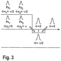
- the two input pulses Px 2 and Py 2 interfere according to the respective set phase at the first intensity beam splitter, taking into account the phase jump that occurs, constructively for the following long path of the delay line 1 and destructively for the short path.
- these two pulses interfere constructively in the output direction to form a single light pulse.
- the number of input pulses and delay lines can be increased accordingly.
- the static phase pattern to be created for the two spatially separated pulse trains can be calculated according to the algorithm already explained or with the help of the differential coding algorithm.
- the temporally separated pulses Pxi and Pyi are numbered with the numbers 0 to N-1 in binary notation, where N-1 is the temporally first light pulse and 0 is the temporally last light pulse.
- the number N is added to these values in order to treat the second spatial pulse train Pyi.
- For the first spatial pulse train Pxi no addition takes place, but a leading 0 is added to the number in binary notation.
- the bit patterns Xxi and Xyi for the i-th light pulse are calculated using the differential coding algorithm from the least significant to the most significant bit, starting with an imaginary 0.
- the number of set bits in the bit patterns is multiplied by the value - ⁇ /2 to calculate the corresponding phases ⁇ x i and ⁇ y i for each light pulse.
- Table 1 shows a corresponding example for 4 temporal pulses.
- ⁇ i>Table 1 Phase pattern for the combination of 4 temporal pulses using intensity beam splitters ⁇ /i> Pulse Pulse in binary notation Pulse + leading 0 for pulse train Px i Pulse + number N for pulse train Py i Differential coding pattern Xx i for pulse train Px i Differential coding pattern Xy i for pulse train Py i ⁇ x i ⁇ y i 1 00 000 100 000 100 0 - ⁇ /2 2 01 001 101 011 111 - ⁇ -3 ⁇ /2 3 10 010 110 110 010 - ⁇ - ⁇ /2 4 11 011 111 101 001 - ⁇ - ⁇ /2
- phase pattern can be determined by theoretical reversal of the combination process
- Polarization beam splitters are optical components that split an input pulse into two pulse replicas based on its polarization state, e.g. reflecting the s-polarized component and transmitting the p-polarized component. It is again assumed that for each Reflection at one of these beam splitters results in a phase jump of ⁇ /2.
- the polarization state of the input pulse and thus the division ratio can be changed using half-wave plates ⁇ /2. For a half-wave plate with an angle of 22.5° with respect to the p-polarization axis, the input polarization of a p-polarized or s-polarized input pulse is rotated to angles of 45° or -45° with respect to the p-polarization axis.
- this combination of beam splitter and half-wave plate can be used as a combination element for 2 input pulses.
- the pulse trains Pxi and Pyi are p-polarized and s-polarized respectively at the input, so that behind the first polarization beam splitter there is a pulse train with N pulses, each of which has its own polarization state depending on the static phase pattern.
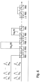
- the required phase patterns for the two pulse trains Pxi and Pyi can be determined with a setup according to Figure 4 as in the combination with intensity beam splitters according to Figure 3 using the algorithms described in previous sections.
Landscapes
- Physics & Mathematics (AREA)
- Electromagnetism (AREA)
- Optics & Photonics (AREA)
- Engineering & Computer Science (AREA)
- Plasma & Fusion (AREA)
- General Physics & Mathematics (AREA)
- Optical Modulation, Optical Deflection, Nonlinear Optics, Optical Demodulation, Optical Logic Elements (AREA)
- Lasers (AREA)
Description
- Die Erfindung betrifft eine optische Anordnung zur Überlagerung einer Sequenz zeitlich äquidistant folgender Lichtpulse innerhalb eines Lichtstrahls zu einem einzelnen Lichtpuls mit
- einem Aufteilungselement, das einen Lichtstrahl in zwei Teilstrahlen aufteilt,
- zwei räumlich voneinander getrennten optischen Elementen, wobei durch jedes der optischen Elemente jeweils einer der Teilstrahlen propagiert, und
- einem Kombinationselement, das die Teilstrahlen in einem Strahl räumlich überlagert.
- Außerdem betrifft die Erfindung ein Verfahren zur Erhöhung der Pulsenergie von Lichtpulsen. Lichtpulse werden im Folgenden Pulse genannt.
- Aufgrund von physikalischen und technischen Limitierungen sind gepulste Lasersysteme bezüglich der Pulsenergien, der Pulsspitzenleistungen und der mittleren Leistung der emittierten Pulse begrenzt. Zu diesen Limitierungen gehören unter anderem die Zerstörung von Komponenten des Systems durch die hohen Intensitäten bzw. Fluenzen der Pulse. Daneben können nichtlineare Effekte wie die Selbstphasenmodulation die zeitliche Form des Pulses verändern, was einen negativen Einfluss auf Parameter wie z.B. die Pulslänge haben kann und in Hinblick auf die gewünschte Anwendung zu einer Unbrauchbarkeit führen kann.
- Dabei sind im Stand der Technik bereits mehrere Ansätze zur Vermeidung dieser Leistungslimitierungen beschrieben:
- Die Spitzenintensität des Pulses kann durch eine Vergrößerung des Laserstrahls beim Durchgang durch die Komponenten des Systems verringert werden [1]. Dazu gehört im Bereich der Faserlaser die Vergrößerung des Kerndurchmessers für den Signalstrahl. Zusätzlich ist eine zeitliche Streckung der Pulse mit Hilfe des Chirped-Pulse-Amplification (CPA) Konzepts [2] möglich, was neben einer Reduzierung der Spitzenintensität auch eine Reduzierung der Spitzenleistung möglich macht.
- Durch Verwendung von zirkularer Polarisation kann der effektive nichtlineare Koeffizient im Material reduziert werden, was den Einfluss von nichtlinearen Effekten auf den Puls reduziert [3].
- Bei diesem Verfahren wird ein Puls in mehrere räumlich getrennte Pulse aufgeteilt, die in den jeweiligen Kanälen z.B. in jeweils einem optischen Verstärker einzeln verstärkt [4] oder spektral verbreitert werden [5]. Nach diesem Prozess findet eine kohärente Kombination in einen einzelnen Strahl bzw. einzelnen Puls statt. Die Durchschnittsleistung des kombinierten Laserstrahls sowie die Energie der kombinierten Pulse können dabei erheblich über den Limitierungen liegen, die von einem einzelnen Kanal vorgegeben werden.
- Beim Divided-Pulse-Amplification (DPA) Konzept, wird ein Eingangspuls vor der Verstärkung in einem optischen Verstärker in mehrere zeitlich getrennte Replikate aufgeteilt. Diese werden einzeln zeitlich hintereinander verstärkt [6] bzw. spektral verbreitert [7]. Darauffolgend werden die einzelnen Replikate wieder zu einem einzigen Puls kombiniert. Der resultierende Puls kann daher Pulsparameter aufweisen, die über den Limitierungen der Komponenten des Lasersystems (mit Ausnahme des Kombinationselementes selbst) für einen einzigen Puls liegen.
- In einem Überhöhungsresonator werden mehrere Pulse eines von einem Lasersystem emittierten Pulszugs zeitlich überlagert [8]. Innerhalb dieses Resonators entsteht dadurch ein umlaufender Puls, der gegenüber den Eingangspulsen deutlich erhöhte Pulsspitzenleistungen und Pulsenergien aufweisen kann.
- In einer Abfolge optischer Resonatoren geringer Güte kann eine Sequenz von Lichtpulse innerhalb eines Lichtstrahles zeitlich überlagert werden [9]. Die relative optische Phase der Lichtpulse muss durch ein optisches Phasenstellglied von Puls zu Puls eingestellt werden. In diesem Verfahren entsteht immer ein Vorpuls relativ zum zeitlich überlagerten Puls. Der überlagerte Puls kann Pulsparameter aufweisen, die über den Limitierungen der Komponenten des Lasersystems (mit Ausnahme der Kombinationselemente selbst) liegt.
- Die Erfindung betrifft eine Verbesserung der heute bekannten Ansätze zu DPA (Siehe D). Bei diesen Ansätzen findet an einer Stelle des Lasersystems eine Aufteilung eines einzelnen Pulses in einen Pulszug statt. Gefolgt wird diese von einem optischen Verstärker oder einer Vorrichtung zur spektralen Verbreiterung der Pulse. Schlussendlich werden die Pulse wieder zu einem einzelnen Ausgangspuls kombiniert. Um diese Kombination erfolgreich zu realisieren, müssen die Pulse einen möglichst großen zeitlichen Überlapp besitzen und ihre Phase muss (Modulo 2π) übereinstimmen. Ist dies nicht der Fall, so kommt es zu einer Reduktion der Kombinationseffizienz. Kombinationseffizienz ist dabei definiert als das Verhältnis der Leistung im erzeugten Puls zu der gesamten emittierten Leistung des Lasersystems. Die Systeme können in passiv stabilisierte Systeme und in aktive stabilisierte Systeme eingeteilt werden. Bei Ersteren wird zum Aufteilen der Pulse derselbe Aufbau wie zur Kombination benutzt, z.B. durch einen Doppeldurchgang [10]. Da in der Summe jedes der Pulsreplikate von der Aufteilung bis zur Kombination denselben Weg durchläuft, sind die jeweiligen Weglängen intrinsisch gleich und die Pulse damit phasengleich, sofern sie nicht durch weitere Effekte bei der Pulspropagation (z.B. durch Dispersion oder nichtlineare Effekte) unterschiedlich beeinflusst werden. Allerdings ist es nur begrenzt möglich die Pulsreplikate einzeln zu beeinflussen. Werden unterschiedliche Aufbauten für die Aufteilung und Kombination verwendet, so ist eine aktive Stabilisierung notwendig um die Weglängen im Aufteilungs- und Kombinationsschritt entsprechend abzugleichen [11]. Hier ist nun eine Beeinflussung der einzelnen Pulsreplikate möglich um z.B. Sättigungseffekten in optischen Verstärkern entgegenzuwirken und dadurch eine bessere Kombinationseffizienz zu erreichen. Allerdings steigt die Anzahl der benötigten Komponenten entsprechender Aufbauten im Vergleich zum passiv stabilisierten Fall stark an. Marco Kienel et al., "Multidimensional coherent pulse addition of ultrashort laser pulses", OPTICS LETTERS, Bd. 40, Nr. 4, 15. Februar 2015 (2015-02-15), Seiten 522-525 offenbart eine Anordnung zur Überlagerung von räumlich und zeitlich aufgespaltenen ultrakurzen Laserpulsen.
- Der Erfindung liegt die Aufgabe zu Grunde, eine verbesserte Methode zur Erhöhung der Pulsenergie aufzuzeigen. Die oben beschriebenen Nachteile des Standes der Technik, insbesondere der starke Anstieg benötigter optischer Komponenten, sollen möglichst vermieden werden.
- Die Erfindung schlägt ausgehend von einer optischen Anordnung der eingangs genannten Art eine optische Anordnung gemäß Anspruch 1 vor, worin eine Anzahl von zeitlich aufeinander folgenden Pulsen in einem einzigen Puls im Ausgangsstrahl überlagert werden.
- Außerdem löst die Erfindung die Aufgabe durch ein Verfahren zur Erhöhung der Pulsenergie von Lichtpulsen gemäß Anspruch 8.
- Erfindungsgemäß werden dabei die zeitlich aufeinander folgenden Pulse in einen einzigen Puls im Ausgangsstrahl überlagert.
- In dem hier beschriebenen Ansatz werden mehrere von einem Lasersystem emittierte und zeitlich getrennte Pulse eines Pulszuges (im Folgenden Eingangspulszug genannt) mit Hilfe einer geeigneten Anordnung zu einem einzelnen Puls kombiniert. Ein getrennter Aufteilungsschritt eines einzelnen Pulses in mehrere Pulsreplikate findet nicht mehr statt. Der Eingangspulszug soll dabei aus N Pulsen bestehen, wobei N eine Potenz der Zahl 2 darstellt (N=2, 4, 8, ...). Die einzelnen Pulse sind zeitlich äquidistant, was z.B. bei Pulsen der Fall ist, die von modengekoppelten Laseroszillatoren emittiert werden.
- Um die angestrebte Kombination der Pulse zu erreichen, findet zuerst eine räumliche Aufteilung des Eingangspulszuges in zwei räumlich getrennte Teilstrahlen statt, in denen sich jeweils ein optisches Element, z.B. ein optischer Verstärker bzw. mehrere räumlich getrennte Verstärker (mit entsprechender Pulsaufteilung und -kombination) befinden können. Anstelle von optischen Verstärkern können hier auch Komponenten zur spektralen Verbreiterung oder andere optische Komponenten verwendet werden. In diesen beiden Teilstrahlen werden, jeweils über einen geeigneten Mechanismus, z.B. mit Hilfe elektrooptischer Modulatoren, relative Phasen auf die Pulszüge aufgeprägt. Dabei wird jedem Lichtpuls innerhalb des Pulszuges eine eigene relative Phase zugeordnet, deren Gesamtheit im Folgenden als (statische) Phasenmuster bezeichnet wird und deren Ableitung später erklärt wird. Über eine Anordnung von Intensitätsstrahlteilern oder Polarisationsstrahlteilern und Wellenplatten können die beiden räumlich getrennte Strahlen in einen einzelnen Ausgangsstrahl und die zeitlich getrennten Pulse der Pulszüge mit Hilfe optischer Verzögerungsstrecken geeigneter Länge zu einem einzelnen Lichtpuls kombiniert werden. Dabei werden für N Pulse log2(N) verschieden lange Verzögerungstrecken benötigt. Die kürzeste der Verzögerungsstrecken erzeugt dabei eine Propagationszeitdifferenz die dem minimalen zeitlichen Abstand zweier Pulse innerhalb des Pulszuges entspricht. Alle weiteren Verzögerungsstrecken sind jeweils immer doppelt so lang wie die Vorherige. Dabei bewirken die anzulegenden Phasenmuster, dass die Pulse im räumlich überlagerten Strahl zu einem einzelnen Puls zeitlich überlagert werden. Die räumliche Abfolge der Verzögerungsstrecken ist frei wählbar unter Verwendung des jeweils korrekten Phasenmuster. Bestehen zwischen den einzelnen Pulsen des Eingangspulszuges zusätzliche zeitlich variierende Phasenunterschiede, so können diese durch Modifikation der durch die Modulatoren aufgeprägten statischen Phasenmuster mit dynamischen Phasenmustern ausgeglichen werden. Darüber hinaus sollten die Längen der einzelnen Wegstrecken in der Kombinationsanordnung auf die zeitlichen Pulsabstände angepasst werden. Dies kann durch eine aktive Kontrolle der entsprechenden Weglängen mittels geeigneter Stellelemente realisiert werden, sowie ebenfalls durch Modifikation des Eingangspulszuges mit Hilfe der vorhandenen oder zusätzlich eingebrachten Phasenmodulatoren erfolgen.
- Die benannten statischen Phasenmuster lassen sich durch gedachte Aufspaltung eines einzelnen Lichtpulses in die Pulsfolgen der zwei Teilstrahlen durch umgekehrte Ausbreitung durch die Elemente zur zeitlichen und räumlichen Überlagerung ableiten. Die relative optische Phase eines jeden einzelnen Pulses innerhalb eines Pulszuges ergibt sich dabei durch das Zählen der benötigten Reflexionen an Strahlteilern, die zur Erzeugung dieses Pulses benötigt wird. Die Zahl der Reflexionen wird mit dem Ausdruck π/2 multipliziert und durch 2π geteilt mit Rest (Modulo 2π). Eine weitere Berechnungsmöglichkeit stellt der Differential Coding Algorithmus dar, der im Zusammenhang mit einem Ausführungsbeispiel später erläutert wird.
- Erfindungsgemäß sind zwei oder mehr räumlich voneinander getrennte optische Elemente vorgesehen, wobei durch jedes der optischen Elemente jeweils einer der Teilstrahlen propagiert. Dadurch lassen sich die Pulse der beiden Teilstrahlen vollständig getrennt voneinander beeinflussen. Der Aufbau kann faserbasiert realisiert werden.
- Wenigstens eines der optischen Elemente kann in einer möglichen Ausgestaltung ein optischer Verstärker, ein nichtlineares optisches Element zur spektralen Verbreiterung, eine Linse, ein Spiegel oder ein Lichtmodulator sein.
- Außerdem ist, wie oben erwähnt, in jedem Teilstrahl - vor oder hinter dem optischen Element - ein Phasenanpassungselement vorgesehen, das die Phase der Strahlung wenigstens eines Teilstrahls beeinflusst. Dabei ist das Phasenanpassungselement ein Phasenmodulator (z.B. ein elektrooptischer Modulator), der die relative Phase der Pulse von Lichtpuls zu Lichtpuls variiert und dadurch die geforderten Phasenmuster auf die Pulszüge aufprägt.
- Das Kombinationselement umfasst eine Mehrzahl von in Strahlrichtung hintereinander angeordneten Strahlteilern, wobei die Pulse zwischen den Strahlteilern Verzögerungsstrecken durchlaufen. Für die Überlagerung von N aufeinander folgenden Pulsen müssen dabei log2(N) Verzögerungsstrecken vorgesehen sein. Die Verzögerungsstrecken sollten unterschiedliche Längen haben, damit die an einem der Strahlteiler zur Überlagerung gebrachten Pulse, die diesem Strahlteiler über die unterschiedlich langen Verzögerungsstrecken zugeführt werden, relativ zueinander eine geeignete zeitliche Verzögerung aufweisen, so dass im Ergebnis die zeitlich aufeinanderfolgenden Pulse des Eingangspulszuges im Ausgangspulszug überlagert werden.
- Vorzugsweise ist zur Einstellung und Regelung der Überlagerung der Pulse wenigstens ein Stellelement vorgesehen, das zur Verstellung der Länge einer diesem Stellelement zugeordneten Verzögerungsstrecke geeignet ist. Zweckmäßig ist zu jedem Strahlteilerpaar des Kombinationselementes ein solches Stellelement vorgesehen, das die Länge einer der (beiden) Verzögerungsstrecken zwischen den Strahlteilern verstellt.
- Ausführungsbeispiele der Erfindung werden im Folgenden anhand der Zeichnungen näher erläutert. Es zeigen:
- Fig. 1:
- optische Anordnung für die Aufteilung eines Eingangspulszuges in zwei räumlich getrennte Kanäle mit jeweils einem Phasenmodulator,
- Fig. 2:
- optische Anordnung für die Kombination mit Hilfe von Intensitätsstrahlteilern für N Pulsreplikate,
- Fig. 3:
- optische Anordnung gemäß
Fig. 2 für 3 Pulsreplikate, - Fig. 4:
- optische Anordnung für die Kombination mit Hilfe von Polarisationsstrahlteilern für N Pulsreplikate.
- In der
Figur 1 ist der Aufbau für die Aufteilung eines aus N Pulsen P1 - PN bestehender Eingangspulszug in zwei räumlich getrennte Teilstrahlen mit den Pulsen PxN bzw. PyN mit jeweils einem Phasenmodulator ΔΦx und ΔΦy dargestellt, der die entsprechenden Phasenmuster für die folgende räumliche und zeitliche Kombination erzeugt. Als Beispiel enthält jeder Kanal einen optischen Verstärker. - Anstelle von optischen Verstärkern können hier auch Komponenten zur spektralen Verbreiterung oder andere optische Komponenten verwendet werden. In den beiden Teilstrahlen werden jeweils über einen geeigneten Mechanismus, z.B. mit Hilfe elektrooptischer Modulatoren, zeitliche statische Phasenmuster auf die Pulszüge aufgeprägt. Dabei wird jedem Lichtpuls des Pulszuges eine eigene Phase zugeordnet. Über eine Anordnung aus Intensitätsstrahlteilern oder Polarisationsstrahlteilern und Wellenplatten werden die beiden räumlich getrennte Strahlen in einem einzelnen Ausgangsstrahl und die zeitlich getrennten Pulse der Pulszüge mit optischen Verzögerungsstrecken zu einem einzelnen Lichtpuls kombiniert. Dabei werden für N Pulse log2(N) Verzögerungstrecken benötigt. Jede dieser Verzögerungsstrecken erzeugt eine Differenz der Propagationszeiten für die Pulse. Die Propagationszeitdifferenzen dieser Strecken werden dabei in diesem Beispiel vom Eingangspulszug her gesehen immer halbiert, wobei die kürzeste Propagationszeitdifferenz dem zeitlichen Abstand zweier aufeinanderfolgender Pulse des Eingangspulszuges entspricht. Im Allgemeinen ist die räumliche Abfolge der Verzögerungsstrecken frei wählbar unter Verwendung des jeweils erforderlichen Phasenmusters.
- In der
Figur 2 ist beispielhaft der Aufbau für die Kombination mit Hilfe von Intensitätsstrahlteilern für N Pulse dargestellt. Als Intensitätsstrahlteiler werden optische Komponenten bezeichnet, die einen Eingangspuls in zwei Pulse aufteilen, wobei die Polarisationseigenschaften erhalten bleiben. Eine solche Komponente kann andersherum auch als Kombinationselement verwendet werden, um zwei Eingangspulse mit gleichen Polarisationseigenschaften in einen Lichtpuls zu kombinieren. Das Verhältnis der Pulsenergien der Pulse ist dabei in den meisten Fällen 1:1, kann aber in bestimmten Fällen auch abweichend gewählt werden. Es wird angenommen, dass bei jeder Reflexion an einem dieser Strahlteiler ein Phasensprung von π/2 auftritt. - Als Beispiel kann ein Aufbau mit N=2 Eingangspulsen betrachtet werden, wie in
Figur 3 dargestellt. Dieser erfordert eine Verzögerungsstrecke. Die zwei Eingangspulse Px2 und Py2 interferieren gemäß der jeweils eingestellten Phase am ersten Intensitätsstrahlteiler unter Berücksichtigung des auftretenden Phasensprungs für den folgenden langen Weg der Verzögerungsstrecke 1 konstruktiv und für den kurzen Weg destruktiv. Für die Pulse Px1 und Py1 passiert entsprechend das Gegenteil. Damit befindet sich in beiden Wegen der Verzögerungsstrecke 1 nur noch jeweils ein Lichtpuls. Am zweiten Intensitätsstrahlteiler interferieren diese beiden Pulse konstruktiv in Ausgangsrichtung zu einem einzelnen Lichtpuls. Entsprechend kann die Anzahl der Eingangspulse und der Verzögerungsstrecken erhöht werden. - Im Fall für N Pulse und einer Folge optischer Verzögerungsstrecken absteigender Länge kann das zu erstellende statische Phasenmuster für die zwei räumlich getrennten Pulszüge gemäß des bereits erklärten Algorithmus oder auch mit Hilfe des Differential-Coding Algorithmus berechnet werden. Für Letzteren werden die zeitlich getrennten Pulse Pxi und Pyi (erster und zweiter räumlicher Pulszug) mit den Zahlen 0 bis N-1 in Binärschreibweise nummeriert, wobei N-1 der zeitlich erste Lichtpuls und 0 der zeitlich letzte Lichtpuls ist. Zu diesen Werten wird die Zahl N addiert, um den zweiten räumlichen Pulszug Pyi zu behandeln. Für den ersten räumlichen Pulszug Pxi findet keine Addition statt, sondern es wird eine führende 0 zu der Zahl in Binärschreibweise ergänzt. Die Bitmuster Xxi und Xyi für den i-ten Lichtpuls werden mit Hilfe des Differential-Coding Algorithmus vom niederwertigsten zum höherwertigsten Bit berechnet, beginnend mit einer imaginären 0. Die Anzahl der gesetzten Bits in den Bitmustern wird mit dem Wert -π/2 multipliziert um die entsprechenden Phasen Φxi und Φyi für jeden Lichtpuls zu berechnen. In Tabelle 1 ist ein entsprechendes Beispiel für 4 zeitliche Pulse dargestellt.
Tabelle 1: Phasenmuster für die Kombination von 4 zeitlichen Pulsen mit Hilfe von Intensitätsstrahlteilern Puls Puls in binärer Schreibweise Puls + führende 0 für Pulszug Pxi Puls + Zahl N für Pulszug Pyi Differential-coding Muster Xxi für Pulszug Pxi Differential-coding Muster Xyi für Pulszug Pyi Φxi Φyi 1 00 000 100 000 100 0 -π/2 2 01 001 101 011 111 -π -3π/2 3 10 010 110 110 010 -π -π/2 4 11 011 111 101 001 -π -π/2 - Im allgemeinen Fall einer ungeordneten Folge optischer Verzögerungsstrecken kann das Phasenmuster durch theoretische Umkehr des Kombinationsprozesses
- In der
Figur 4 ist der Aufbau für die Kombination mit Hilfe von Polarisationsstrahlteilern PBS für N Pulsreplikate dargestellt. - Als Polarisationsstrahlteiler werden optische Komponenten bezeichnet, die einen Eingangspuls anhand seines Polarisationszustands in zwei Pulsreplikate aufteilen, z.B. die s-polarisierte Komponente reflektieren und die p-polarisierte Komponente transmittieren. Es wird wiederum angenommen, dass bei jeder Reflexion an einem dieser Strahlteiler ein Phasensprung von π/2 auftritt. Über Halbwellenplatten λ/2 kann der Polarisationszustand des Eingangspulses und somit das Teilungsverhältnis verändert werden. Für eine Halbwellenplatte mit einem Winkel von 22.5° bzgl. der p-Polarisationsachse ergibt sich eine Drehung der Eingangspolarisation eines p-polarisierten bzw. s-polarisierten Eingangspulses auf Winkel von 45° bzw. -45° bzgl. der p-Polarisationsachse. Damit ergibt sich bei einem folgenden Polarisationsstrahlteiler eine Teilung in zwei Pulse mit einem Verhältnis von 1:1. Wie im Aufbau mit Intensitätsstrahlteilern kann diese Kombination aus Strahlteiler und Halbwellenplatte als Kombinationselement für 2 Eingangspulse verwendet werden. Damit lässt sich der Aufbau mit Intensitätsstrahlteilern auf Polarisationsstrahlteiler übertragen. Dabei sind die Pulszüge Pxi und Pyi am Eingang p-polarisiert bzw. s-polarisiert, es ergibt sich also hinter dem ersten Polarisationsstrahlteiler ein Pulszug mit N Pulsen, die jeweils einen eigenen Polarisationszustand in Abhängigkeit der statischen Phasenmuster aufweisen. Die erforderlichen Phasenmuster für die beiden Pulszüge Pxi und Pyi lassen sich bei einem Aufbau gemäß
Figur 4 wie bei der Kombination mit Intensitätsstrahlteilern gemäßFigur 3 anhand der in vorherigen Abschnitten beschriebenen Algorithmen berechnen. - In der vorstehenden Beschreibung zitierter Stand der Technik:
- 1. J. Limpert, F. Stutzki, F. Jansen, H.-J. Otto, T. Eidam, C. Jauregui, and A. Tünnermann, "Yb-doped large-pitch fibres: effective single-mode operation based on higher-order mode delocalisation," Light Sci. Appl. 1, e8 (2012).
- 2. D. Strickland and G. Mourou, "Compression of amplified chirped optical pulses," Opt. Commun. 56, 219-221 (1985).
- 3. D. N. Schimpf, T. Eidam, E. Seise, S. Hädrich, J. Limpert, and A. Tünnermann, "Circular versus linear polarization in laser-amplifiers with Kerrnonlinearity.," Opt. Express 17, 18774-81 (2009).
- 4. T. Y. Fan, "Laser beam combining for high-power, high-radiance sources," IEEE J. Sel. Top. Quantum Electron. 11, 567-577 (2005).
- 5. A. Klenke, S. Hädrich, M. Kienel, T. Eidam, J. Limpert, and A. Tünnermann, "Coherent combination of spectrally broadened femtosecond pulses for nonlinear compression.," Opt. Lett. 39, 3520-2 (2014).
- 6. S. Zhou, F. W. Wise, and D. G. Ouzounov, "Divided-pulse amplification of ultrashort pulses," Opt. Lett. 32, 871 (2007).
- 7. A. Klenke, M. Kienel, T. Eidam, S. Hädrich, J. Limpert, and A. Tünnermann, "Divided-pulse nonlinear compression," Opt. Lett. 38, 4593-6 (2013).
- 8. I. Pupeza, T. Eidam, J. Rauschenberger, B. Bernhardt, A. Ozawa, E. Fill, A. Apolonski, T. Udem, J. Limpert, Z. A. Alahmed, A. M. Azzeer, A. Tünnermann, T. W. Hänsch, and F. Krausz, "Power scaling of a high-repetition-rate enhancement cavity," Opt. Lett. 35, 2052-2054 (2010).
- 9. Tong Zhou, John Ruppe, Cheng Zhu, I-Ning Hu, John Nees, and Almantas Galvanauskas, "Coherent pulse stacking amplification using low-finesse Gires-Tournois interferometers," Opt. Express 23, 6, 7442-7462 (2015)
- 10. F. Guichard, Y. Zaouter, M. Hanna, K.-L. Mai, F. Morin, C. Hönninger, E. Mottay, and P. Georges, "High-energy chirped- and divided-pulse Sagnac femtosecond fiber amplifier.," Opt. Lett. 40, 89-92 (2015).
- 11. M. Kienel, A. Klenke, T. Eidam, S. Hädrich, J. Limpert, and A. Tünnermann, "Energy scaling of femtosecond amplifiers using actively controlled divided-pulse amplification.," Opt. Lett. 39, 1049-52 (2014).
Claims (10)
- Optische Anordnung zur Überlagerung einer Sequenz von zeitlich äquidistant folgenden Lichtpulsen innerhalb eines Lichtstrahls zu einem einzelnen Lichtpuls mit- einem Aufteilungselement, das den Lichtstrahl in zwei Teilstrahlen aufteilt,- zwei räumlich voneinander getrennten optischen Elementen, wobei durch jedes der optischen Elemente jeweils einer der Teilstrahlen propagiert, und- wenigstens einem Kombinationselement, das die Teilstrahlen in einem Strahl räumlich überlagert, wobei das Kombinationselement eine Anzahl der zeitlich aufeinander folgenden Lichtpulse in einem einzigen Lichtpuls im Ausgangsstrahl überlagert, wobei das Kombinationselement eine Mehrzahl von in Strahlrichtung hintereinander angeordneten Strahlteilern aufweist, wobei die Lichtpulse zwischen den Strahlteilern Verzögerungsstrecken durchlaufen,dadurch gekennzeichnet, dass in jedem Teilstrahl in Strahlrichtung vor oder hinter dem optischen Element ein Phasenanpassungselement angeordnet ist, wobei das Phasenanpassungselement ein Phasenmodulator ist, der die Phase der Lichtpulse von Lichtpuls zu Lichtpuls variiert und so jedem Lichtpuls eine eigene relative Phase zuordnet, deren Gesamtheit ein Phasenmuster bildet, das bewirkt, dass die Anzahl von Lichtpulsen in dem räumlich überlagerten Strahl zu dem einzelnen Lichtpuls überlagert werden, wobei die verschiedenen Strahlteilerpaaren zugeordneten Verzögerungsstrecken unterschiedlich lang sind.
- Optische Anordnung nach Anspruch 1, dadurch gekennzeichnet, dass die optischen Elemente optische Fasern sind, wobei jede der Fasern jeweils einen der Teilstrahlen führt.
- Optische Anordnung nach einem der Ansprüche 1 oder 2, dadurch gekennzeichnet, dass das wenigstens ein optisches Element ein optischer Verstärker, ein nichtlineares optisches Element zur spektralen Verbreiterung, ein Spiegel, ein Lichtmodulator oder eine Linse ist.
- Optische Anordnung nach einem der Ansprüche 1 bis 3, dadurch gekennzeichnet, dass für N Lichtpulse log2(N) unterschiedlich lange Verzögerungsstrecken vorgesehen sind.
- Optische Anordnung nach einem der Ansprüche 1 bis 4, gekennzeichnet durch wenigstens ein Stellelement, das zur Verstellung der Länge einer diesem Stellelement zugeordneten Verzögerungsstrecke geeignet ist.
- Optische Anordnung nach einem der Ansprüche 1 bis 5, dadurch gekennzeichnet, dass die Strahlteiler Polarisationsstrahlteiler sind, wobei sich zwischen den Strahlteilern Halbwellenplatten befinden.
- Optische Anordnung nach einem der Ansprüche 1 bis 6, dadurch gekennzeichnet, dass die Strahlteiler Intensitätsstrahlteiler sind.
- Verfahren zur Erhöhung der Pulsenergie von Lichtpulsen, mit den Verfahrensschritten:- Erzeugen einer Lichtpulsfolge, bestehend aus einer Abfolge von zeitlich äquidistanten Lichtpulsen in einem Eingangsstrahl,- Aufteilen der Lichtpulse auf zwei räumlich getrennte Teilstrahlen, wobei jeder der Teilstrahlen jeweils durch eines von zwei räumlich getrennten optischen Elementen propagiert.- räumliche Überlagerung der Teilstrahlen in einem Ausgangsstrahl, wobei eine Anzahl der zeitlich aufeinanderfolgenden Lichtpulse in einem einzigen Lichtpuls im Ausgangsstrahl überlagert werden, wobei die Überlagerung der Lichtpulse im Ausgangsstrahl mittels einer Mehrzahl von in Strahlrichtung hintereinander angeordneten Strahlteilern erfolgt, wobei die Lichtpulse zwischen den Strahlteilern Verzögerungsstrecken durchlaufendadurch gekennzeichnet, dass die Phasen der Lichtpulse in jedem der Teilstrahlen durch einen in Strahlrichtung vor oder hinter dem optischen Element angeordneten Phasenmodulator von Lichtpuls zu Lichtpuls gesteuert werden, so dass jedem Lichtpuls eine eigene relative Phase zugeordnet wird, deren Gesamtheit ein Phasenmuster bildet, das bewirkt, dass die Anzahl von Lichtpulsen in dem räumlich überlagerten Strahl zu dem einzelnen Lichtpuls überlagert werden, wobei die verschiedenen Strahlteilerpaaren zugeordneten Verzögerungsstrecken unterschiedlich lang sind.
- Verfahren nach Anspruch 8, dadurch gekennzeichnet, dass die relative Phase für jeden einzelnen Lichtpuls durch Division mit Rest durch 2π des Produktes aus der Anzahl der Reflexionen an Strahlteilern für diesen Lichtpuls mit π/2 bestimmt wird.
- Verfahren nach Anspruch 8, dadurch gekennzeichnet, dass die relative Phase für jeden einzelnen Lichtpuls nach dem Differential Coding Algorithmus bestimmt wird.
Applications Claiming Priority (2)
| Application Number | Priority Date | Filing Date | Title |
|---|---|---|---|
| DE102015122734 | 2015-12-23 | ||
| PCT/EP2016/081976 WO2017108825A1 (de) | 2015-12-23 | 2016-12-20 | Optische anordnung |
Publications (2)
| Publication Number | Publication Date |
|---|---|
| EP3394938A1 EP3394938A1 (de) | 2018-10-31 |
| EP3394938B1 true EP3394938B1 (de) | 2024-06-19 |
Family
ID=57851024
Family Applications (1)
| Application Number | Title | Priority Date | Filing Date |
|---|---|---|---|
| EP16828936.1A Active EP3394938B1 (de) | 2015-12-23 | 2016-12-20 | Optische anordnung |
Country Status (3)
| Country | Link |
|---|---|
| US (1) | US11043783B2 (de) |
| EP (1) | EP3394938B1 (de) |
| WO (1) | WO2017108825A1 (de) |
Families Citing this family (3)
| Publication number | Priority date | Publication date | Assignee | Title |
|---|---|---|---|---|
| WO2017108825A1 (de) | 2015-12-23 | 2017-06-29 | Fraunhofer-Gesellschaft zur Förderung der angewandten Forschung e. V. | Optische anordnung |
| US11121519B2 (en) * | 2017-12-19 | 2021-09-14 | Imra America, Inc. | Utilization of time and spatial division multiplexing in high power ultrafast optical amplifiers |
| EP3993181A1 (de) * | 2020-11-03 | 2022-05-04 | Deutsches Elektronen-Synchrotron DESY | Bereitstellung ultraschneller hochenergetischer laserpulse |
Family Cites Families (2)
| Publication number | Priority date | Publication date | Assignee | Title |
|---|---|---|---|---|
| WO2015095751A1 (en) | 2013-12-19 | 2015-06-25 | The Regents Of The University Of Michigan | Coherently combining pulse bursts in time domain |
| WO2017108825A1 (de) | 2015-12-23 | 2017-06-29 | Fraunhofer-Gesellschaft zur Förderung der angewandten Forschung e. V. | Optische anordnung |
-
2016
- 2016-12-20 WO PCT/EP2016/081976 patent/WO2017108825A1/de not_active Ceased
- 2016-12-20 EP EP16828936.1A patent/EP3394938B1/de active Active
- 2016-12-20 US US16/065,829 patent/US11043783B2/en active Active
Also Published As
| Publication number | Publication date |
|---|---|
| EP3394938A1 (de) | 2018-10-31 |
| WO2017108825A1 (de) | 2017-06-29 |
| US11043783B2 (en) | 2021-06-22 |
| US20190013637A1 (en) | 2019-01-10 |
Similar Documents
| Publication | Publication Date | Title |
|---|---|---|
| EP3552279B1 (de) | Erzeugung von laserpulsen in einem burstbetrieb | |
| EP2612405B1 (de) | Optische verstärkeranordnung | |
| WO2020074581A1 (de) | Multi-apertur-lasersystem | |
| EP3103167B1 (de) | Optische anordnung mit strahlaufteilung | |
| EP2908168A1 (de) | Erzeugung von Frequenzkämmen und sinc-förmigen Nyquist-Pulsefolgen großer Bandbreite und abstimmbarer Repetitionsrate | |
| EP3622590A1 (de) | Kurzpulslaser mit hohem zeitlichen kontrast | |
| EP3394938A1 (de) | Optische anordnung | |
| DE102016108282B4 (de) | Lasersystem mit Überlagerung von zeitlich oder räumlich separaten Laserpulsen | |
| DE102009011599B4 (de) | Oszillator-Verstärker-Anordnungen mit Amplituden-Einstellung | |
| DE102020122731A1 (de) | Kurzpuls-Lasersystem und Verfahren zur Erzeugung von Laserpulsen | |
| DE102020115753B3 (de) | Kurzpuls-Lasersystem | |
| EP3590160B1 (de) | Schnelle modulation von laserstrahlung hoher leistung | |
| DE102015200668B4 (de) | Verfahren und System zum Erzeugen eines Treibersignals für ein akusto-optisches Bauelement zur Carrier-Envelope-Phasenstabilisierung | |
| DE3301092A1 (de) | Mehrfarbenlaser | |
| EP4434125A1 (de) | Rückreflexschutz durch verfahren und vorrichtung zur interferenz eines laserpulses | |
| WO2022223780A2 (de) | Kombinationseinrichtung und optisches system | |
| WO2017186590A1 (de) | Ultrakurzpulspumpquelle zur erzeugung mehrerer pumppulse | |
| EP3876368B1 (de) | Vorrichtung zum verstärken und/oder transportieren von elektromagnetischer strahlung | |
| EP1775806B1 (de) | Verfahren zur Erzeugung zeitlich rechteckiger Ultrakurzpulse | |
| DE102015117828B4 (de) | Dielektrischer Mehrschichtspiegel, Laservorrichtung und Verfahren zur Erzeugung von Laserstrahlung | |
| DE19634489C2 (de) | Vorrichtung zur Synchronisation von ultrakurzen optischen Laserimpulsen | |
| EP2246944B1 (de) | Laserverstärker und Laserverstärkungsverfahren | |
| DE102017121147A1 (de) | Erzeugung von Mehrfach-Laserpulsen durch Überlagerung von Laserstrahlung |
Legal Events
| Date | Code | Title | Description |
|---|---|---|---|
| STAA | Information on the status of an ep patent application or granted ep patent |
Free format text: STATUS: UNKNOWN |
|
| STAA | Information on the status of an ep patent application or granted ep patent |
Free format text: STATUS: THE INTERNATIONAL PUBLICATION HAS BEEN MADE |
|
| PUAI | Public reference made under article 153(3) epc to a published international application that has entered the european phase |
Free format text: ORIGINAL CODE: 0009012 |
|
| STAA | Information on the status of an ep patent application or granted ep patent |
Free format text: STATUS: REQUEST FOR EXAMINATION WAS MADE |
|
| 17P | Request for examination filed |
Effective date: 20180723 |
|
| AK | Designated contracting states |
Kind code of ref document: A1 Designated state(s): AL AT BE BG CH CY CZ DE DK EE ES FI FR GB GR HR HU IE IS IT LI LT LU LV MC MK MT NL NO PL PT RO RS SE SI SK SM TR |
|
| AX | Request for extension of the european patent |
Extension state: BA ME |
|
| DAV | Request for validation of the european patent (deleted) | ||
| DAX | Request for extension of the european patent (deleted) | ||
| STAA | Information on the status of an ep patent application or granted ep patent |
Free format text: STATUS: EXAMINATION IS IN PROGRESS |
|
| 17Q | First examination report despatched |
Effective date: 20210217 |
|
| RAP3 | Party data changed (applicant data changed or rights of an application transferred) |
Owner name: FRIEDRICH-SCHILLER-UNIVERSITAET JENA Owner name: FRAUNHOFER-GESELLSCHAFT ZUR FOERDERUNG DER ANGEWANDTEN FORSCHUNG E.V. |
|
| GRAP | Despatch of communication of intention to grant a patent |
Free format text: ORIGINAL CODE: EPIDOSNIGR1 |
|
| STAA | Information on the status of an ep patent application or granted ep patent |
Free format text: STATUS: GRANT OF PATENT IS INTENDED |
|
| INTG | Intention to grant announced |
Effective date: 20240115 |
|
| GRAS | Grant fee paid |
Free format text: ORIGINAL CODE: EPIDOSNIGR3 |
|
| GRAA | (expected) grant |
Free format text: ORIGINAL CODE: 0009210 |
|
| STAA | Information on the status of an ep patent application or granted ep patent |
Free format text: STATUS: THE PATENT HAS BEEN GRANTED |
|
| AK | Designated contracting states |
Kind code of ref document: B1 Designated state(s): AL AT BE BG CH CY CZ DE DK EE ES FI FR GB GR HR HU IE IS IT LI LT LU LV MC MK MT NL NO PL PT RO RS SE SI SK SM TR |
|
| P01 | Opt-out of the competence of the unified patent court (upc) registered |
Effective date: 20240516 |
|
| REG | Reference to a national code |
Ref country code: GB Ref legal event code: FG4D Free format text: NOT ENGLISH |
|
| REG | Reference to a national code |
Ref country code: CH Ref legal event code: EP |
|
| REG | Reference to a national code |
Ref country code: DE Ref legal event code: R096 Ref document number: 502016016594 Country of ref document: DE |
|
| PG25 | Lapsed in a contracting state [announced via postgrant information from national office to epo] |
Ref country code: BG Free format text: LAPSE BECAUSE OF FAILURE TO SUBMIT A TRANSLATION OF THE DESCRIPTION OR TO PAY THE FEE WITHIN THE PRESCRIBED TIME-LIMIT Effective date: 20240619 |
|
| PG25 | Lapsed in a contracting state [announced via postgrant information from national office to epo] |
Ref country code: FI Free format text: LAPSE BECAUSE OF FAILURE TO SUBMIT A TRANSLATION OF THE DESCRIPTION OR TO PAY THE FEE WITHIN THE PRESCRIBED TIME-LIMIT Effective date: 20240619 Ref country code: HR Free format text: LAPSE BECAUSE OF FAILURE TO SUBMIT A TRANSLATION OF THE DESCRIPTION OR TO PAY THE FEE WITHIN THE PRESCRIBED TIME-LIMIT Effective date: 20240619 |
|
| REG | Reference to a national code |
Ref country code: LT Ref legal event code: MG9D |
|
| PG25 | Lapsed in a contracting state [announced via postgrant information from national office to epo] |
Ref country code: GR Free format text: LAPSE BECAUSE OF FAILURE TO SUBMIT A TRANSLATION OF THE DESCRIPTION OR TO PAY THE FEE WITHIN THE PRESCRIBED TIME-LIMIT Effective date: 20240920 |
|
| REG | Reference to a national code |
Ref country code: NL Ref legal event code: MP Effective date: 20240619 |
|
| PG25 | Lapsed in a contracting state [announced via postgrant information from national office to epo] |
Ref country code: LV Free format text: LAPSE BECAUSE OF FAILURE TO SUBMIT A TRANSLATION OF THE DESCRIPTION OR TO PAY THE FEE WITHIN THE PRESCRIBED TIME-LIMIT Effective date: 20240619 |
|
| PG25 | Lapsed in a contracting state [announced via postgrant information from national office to epo] |
Ref country code: NO Free format text: LAPSE BECAUSE OF FAILURE TO SUBMIT A TRANSLATION OF THE DESCRIPTION OR TO PAY THE FEE WITHIN THE PRESCRIBED TIME-LIMIT Effective date: 20240919 Ref country code: LV Free format text: LAPSE BECAUSE OF FAILURE TO SUBMIT A TRANSLATION OF THE DESCRIPTION OR TO PAY THE FEE WITHIN THE PRESCRIBED TIME-LIMIT Effective date: 20240619 Ref country code: HR Free format text: LAPSE BECAUSE OF FAILURE TO SUBMIT A TRANSLATION OF THE DESCRIPTION OR TO PAY THE FEE WITHIN THE PRESCRIBED TIME-LIMIT Effective date: 20240619 Ref country code: GR Free format text: LAPSE BECAUSE OF FAILURE TO SUBMIT A TRANSLATION OF THE DESCRIPTION OR TO PAY THE FEE WITHIN THE PRESCRIBED TIME-LIMIT Effective date: 20240920 Ref country code: FI Free format text: LAPSE BECAUSE OF FAILURE TO SUBMIT A TRANSLATION OF THE DESCRIPTION OR TO PAY THE FEE WITHIN THE PRESCRIBED TIME-LIMIT Effective date: 20240619 Ref country code: BG Free format text: LAPSE BECAUSE OF FAILURE TO SUBMIT A TRANSLATION OF THE DESCRIPTION OR TO PAY THE FEE WITHIN THE PRESCRIBED TIME-LIMIT Effective date: 20240619 Ref country code: RS Free format text: LAPSE BECAUSE OF FAILURE TO SUBMIT A TRANSLATION OF THE DESCRIPTION OR TO PAY THE FEE WITHIN THE PRESCRIBED TIME-LIMIT Effective date: 20240919 |
|
| PG25 | Lapsed in a contracting state [announced via postgrant information from national office to epo] |
Ref country code: NL Free format text: LAPSE BECAUSE OF FAILURE TO SUBMIT A TRANSLATION OF THE DESCRIPTION OR TO PAY THE FEE WITHIN THE PRESCRIBED TIME-LIMIT Effective date: 20240619 |
|
| PG25 | Lapsed in a contracting state [announced via postgrant information from national office to epo] |
Ref country code: NL Free format text: LAPSE BECAUSE OF FAILURE TO SUBMIT A TRANSLATION OF THE DESCRIPTION OR TO PAY THE FEE WITHIN THE PRESCRIBED TIME-LIMIT Effective date: 20240619 |
|
| PG25 | Lapsed in a contracting state [announced via postgrant information from national office to epo] |
Ref country code: PT Free format text: LAPSE BECAUSE OF FAILURE TO SUBMIT A TRANSLATION OF THE DESCRIPTION OR TO PAY THE FEE WITHIN THE PRESCRIBED TIME-LIMIT Effective date: 20241021 |
|
| PG25 | Lapsed in a contracting state [announced via postgrant information from national office to epo] |
Ref country code: PT Free format text: LAPSE BECAUSE OF FAILURE TO SUBMIT A TRANSLATION OF THE DESCRIPTION OR TO PAY THE FEE WITHIN THE PRESCRIBED TIME-LIMIT Effective date: 20241021 |
|
| PG25 | Lapsed in a contracting state [announced via postgrant information from national office to epo] |
Ref country code: PL Free format text: LAPSE BECAUSE OF FAILURE TO SUBMIT A TRANSLATION OF THE DESCRIPTION OR TO PAY THE FEE WITHIN THE PRESCRIBED TIME-LIMIT Effective date: 20240619 |
|
| PG25 | Lapsed in a contracting state [announced via postgrant information from national office to epo] |
Ref country code: EE Free format text: LAPSE BECAUSE OF FAILURE TO SUBMIT A TRANSLATION OF THE DESCRIPTION OR TO PAY THE FEE WITHIN THE PRESCRIBED TIME-LIMIT Effective date: 20240619 |
|
| PG25 | Lapsed in a contracting state [announced via postgrant information from national office to epo] |
Ref country code: IS Free format text: LAPSE BECAUSE OF FAILURE TO SUBMIT A TRANSLATION OF THE DESCRIPTION OR TO PAY THE FEE WITHIN THE PRESCRIBED TIME-LIMIT Effective date: 20241019 |
|
| PG25 | Lapsed in a contracting state [announced via postgrant information from national office to epo] |
Ref country code: CZ Free format text: LAPSE BECAUSE OF FAILURE TO SUBMIT A TRANSLATION OF THE DESCRIPTION OR TO PAY THE FEE WITHIN THE PRESCRIBED TIME-LIMIT Effective date: 20240619 |
|
| PG25 | Lapsed in a contracting state [announced via postgrant information from national office to epo] |
Ref country code: RO Free format text: LAPSE BECAUSE OF FAILURE TO SUBMIT A TRANSLATION OF THE DESCRIPTION OR TO PAY THE FEE WITHIN THE PRESCRIBED TIME-LIMIT Effective date: 20240619 Ref country code: SK Free format text: LAPSE BECAUSE OF FAILURE TO SUBMIT A TRANSLATION OF THE DESCRIPTION OR TO PAY THE FEE WITHIN THE PRESCRIBED TIME-LIMIT Effective date: 20240619 |
|
| PG25 | Lapsed in a contracting state [announced via postgrant information from national office to epo] |
Ref country code: ES Free format text: LAPSE BECAUSE OF FAILURE TO SUBMIT A TRANSLATION OF THE DESCRIPTION OR TO PAY THE FEE WITHIN THE PRESCRIBED TIME-LIMIT Effective date: 20240619 Ref country code: SM Free format text: LAPSE BECAUSE OF FAILURE TO SUBMIT A TRANSLATION OF THE DESCRIPTION OR TO PAY THE FEE WITHIN THE PRESCRIBED TIME-LIMIT Effective date: 20240619 |
|
| PG25 | Lapsed in a contracting state [announced via postgrant information from national office to epo] |
Ref country code: SM Free format text: LAPSE BECAUSE OF FAILURE TO SUBMIT A TRANSLATION OF THE DESCRIPTION OR TO PAY THE FEE WITHIN THE PRESCRIBED TIME-LIMIT Effective date: 20240619 Ref country code: SK Free format text: LAPSE BECAUSE OF FAILURE TO SUBMIT A TRANSLATION OF THE DESCRIPTION OR TO PAY THE FEE WITHIN THE PRESCRIBED TIME-LIMIT Effective date: 20240619 Ref country code: RO Free format text: LAPSE BECAUSE OF FAILURE TO SUBMIT A TRANSLATION OF THE DESCRIPTION OR TO PAY THE FEE WITHIN THE PRESCRIBED TIME-LIMIT Effective date: 20240619 Ref country code: PL Free format text: LAPSE BECAUSE OF FAILURE TO SUBMIT A TRANSLATION OF THE DESCRIPTION OR TO PAY THE FEE WITHIN THE PRESCRIBED TIME-LIMIT Effective date: 20240619 Ref country code: IS Free format text: LAPSE BECAUSE OF FAILURE TO SUBMIT A TRANSLATION OF THE DESCRIPTION OR TO PAY THE FEE WITHIN THE PRESCRIBED TIME-LIMIT Effective date: 20241019 Ref country code: ES Free format text: LAPSE BECAUSE OF FAILURE TO SUBMIT A TRANSLATION OF THE DESCRIPTION OR TO PAY THE FEE WITHIN THE PRESCRIBED TIME-LIMIT Effective date: 20240619 Ref country code: EE Free format text: LAPSE BECAUSE OF FAILURE TO SUBMIT A TRANSLATION OF THE DESCRIPTION OR TO PAY THE FEE WITHIN THE PRESCRIBED TIME-LIMIT Effective date: 20240619 Ref country code: CZ Free format text: LAPSE BECAUSE OF FAILURE TO SUBMIT A TRANSLATION OF THE DESCRIPTION OR TO PAY THE FEE WITHIN THE PRESCRIBED TIME-LIMIT Effective date: 20240619 |
|
| PG25 | Lapsed in a contracting state [announced via postgrant information from national office to epo] |
Ref country code: IT Free format text: LAPSE BECAUSE OF FAILURE TO SUBMIT A TRANSLATION OF THE DESCRIPTION OR TO PAY THE FEE WITHIN THE PRESCRIBED TIME-LIMIT Effective date: 20240619 |
|
| REG | Reference to a national code |
Ref country code: DE Ref legal event code: R097 Ref document number: 502016016594 Country of ref document: DE |
|
| PG25 | Lapsed in a contracting state [announced via postgrant information from national office to epo] |
Ref country code: DK Free format text: LAPSE BECAUSE OF FAILURE TO SUBMIT A TRANSLATION OF THE DESCRIPTION OR TO PAY THE FEE WITHIN THE PRESCRIBED TIME-LIMIT Effective date: 20240619 |
|
| PLBE | No opposition filed within time limit |
Free format text: ORIGINAL CODE: 0009261 |
|
| STAA | Information on the status of an ep patent application or granted ep patent |
Free format text: STATUS: NO OPPOSITION FILED WITHIN TIME LIMIT |
|
| 26N | No opposition filed |
Effective date: 20250320 |
|
| PG25 | Lapsed in a contracting state [announced via postgrant information from national office to epo] |
Ref country code: MC Free format text: LAPSE BECAUSE OF FAILURE TO SUBMIT A TRANSLATION OF THE DESCRIPTION OR TO PAY THE FEE WITHIN THE PRESCRIBED TIME-LIMIT Effective date: 20240619 |
|
| REG | Reference to a national code |
Ref country code: CH Ref legal event code: PL |
|
| PG25 | Lapsed in a contracting state [announced via postgrant information from national office to epo] |
Ref country code: LU Free format text: LAPSE BECAUSE OF NON-PAYMENT OF DUE FEES Effective date: 20241220 |
|
| PG25 | Lapsed in a contracting state [announced via postgrant information from national office to epo] |
Ref country code: SE Free format text: LAPSE BECAUSE OF FAILURE TO SUBMIT A TRANSLATION OF THE DESCRIPTION OR TO PAY THE FEE WITHIN THE PRESCRIBED TIME-LIMIT Effective date: 20240619 |
|
| REG | Reference to a national code |
Ref country code: BE Ref legal event code: MM Effective date: 20241231 |
|
| PG25 | Lapsed in a contracting state [announced via postgrant information from national office to epo] |
Ref country code: BE Free format text: LAPSE BECAUSE OF NON-PAYMENT OF DUE FEES Effective date: 20241231 |
|
| PG25 | Lapsed in a contracting state [announced via postgrant information from national office to epo] |
Ref country code: CH Free format text: LAPSE BECAUSE OF NON-PAYMENT OF DUE FEES Effective date: 20241231 |
|
| PG25 | Lapsed in a contracting state [announced via postgrant information from national office to epo] |
Ref country code: IE Free format text: LAPSE BECAUSE OF NON-PAYMENT OF DUE FEES Effective date: 20241220 |
|
| PGFP | Annual fee paid to national office [announced via postgrant information from national office to epo] |
Ref country code: GB Payment date: 20251218 Year of fee payment: 10 |
|
| PGFP | Annual fee paid to national office [announced via postgrant information from national office to epo] |
Ref country code: FR Payment date: 20251218 Year of fee payment: 10 |
|
| REG | Reference to a national code |
Ref country code: AT Ref legal event code: MM01 Ref document number: 1696567 Country of ref document: AT Kind code of ref document: T Effective date: 20241220 |
|
| PGFP | Annual fee paid to national office [announced via postgrant information from national office to epo] |
Ref country code: DE Payment date: 20251222 Year of fee payment: 10 |
|
| PG25 | Lapsed in a contracting state [announced via postgrant information from national office to epo] |
Ref country code: AT Free format text: LAPSE BECAUSE OF NON-PAYMENT OF DUE FEES Effective date: 20241220 |