EP3394388B1 - Anti-chattering valve cone and methods for using same - Google Patents
Anti-chattering valve cone and methods for using same Download PDFInfo
- Publication number
- EP3394388B1 EP3394388B1 EP16879987.2A EP16879987A EP3394388B1 EP 3394388 B1 EP3394388 B1 EP 3394388B1 EP 16879987 A EP16879987 A EP 16879987A EP 3394388 B1 EP3394388 B1 EP 3394388B1
- Authority
- EP
- European Patent Office
- Prior art keywords
- closure member
- fluid
- nose
- outer circumferential
- circumferential surface
- Prior art date
- Legal status (The legal status is an assumption and is not a legal conclusion. Google has not performed a legal analysis and makes no representation as to the accuracy of the status listed.)
- Active
Links
Images


Classifications
-
- F—MECHANICAL ENGINEERING; LIGHTING; HEATING; WEAPONS; BLASTING
- F16—ENGINEERING ELEMENTS AND UNITS; GENERAL MEASURES FOR PRODUCING AND MAINTAINING EFFECTIVE FUNCTIONING OF MACHINES OR INSTALLATIONS; THERMAL INSULATION IN GENERAL
- F16K—VALVES; TAPS; COCKS; ACTUATING-FLOATS; DEVICES FOR VENTING OR AERATING
- F16K47/00—Means in valves for absorbing fluid energy
- F16K47/02—Means in valves for absorbing fluid energy for preventing water-hammer or noise
- F16K47/023—Means in valves for absorbing fluid energy for preventing water-hammer or noise for preventing water-hammer, e.g. damping of the valve movement
-
- E—FIXED CONSTRUCTIONS
- E21—EARTH OR ROCK DRILLING; MINING
- E21B—EARTH OR ROCK DRILLING; OBTAINING OIL, GAS, WATER, SOLUBLE OR MELTABLE MATERIALS OR A SLURRY OF MINERALS FROM WELLS
- E21B21/00—Methods or apparatus for flushing boreholes, e.g. by use of exhaust air from motor
- E21B21/10—Valve arrangements in drilling-fluid circulation systems
-
- E—FIXED CONSTRUCTIONS
- E21—EARTH OR ROCK DRILLING; MINING
- E21B—EARTH OR ROCK DRILLING; OBTAINING OIL, GAS, WATER, SOLUBLE OR MELTABLE MATERIALS OR A SLURRY OF MINERALS FROM WELLS
- E21B21/00—Methods or apparatus for flushing boreholes, e.g. by use of exhaust air from motor
- E21B21/10—Valve arrangements in drilling-fluid circulation systems
- E21B21/103—Down-hole by-pass valve arrangements, i.e. between the inside of the drill string and the annulus
-
- E—FIXED CONSTRUCTIONS
- E21—EARTH OR ROCK DRILLING; MINING
- E21B—EARTH OR ROCK DRILLING; OBTAINING OIL, GAS, WATER, SOLUBLE OR MELTABLE MATERIALS OR A SLURRY OF MINERALS FROM WELLS
- E21B34/00—Valve arrangements for boreholes or wells
- E21B34/06—Valve arrangements for boreholes or wells in wells
-
- F—MECHANICAL ENGINEERING; LIGHTING; HEATING; WEAPONS; BLASTING
- F16—ENGINEERING ELEMENTS AND UNITS; GENERAL MEASURES FOR PRODUCING AND MAINTAINING EFFECTIVE FUNCTIONING OF MACHINES OR INSTALLATIONS; THERMAL INSULATION IN GENERAL
- F16K—VALVES; TAPS; COCKS; ACTUATING-FLOATS; DEVICES FOR VENTING OR AERATING
- F16K1/00—Lift valves or globe valves, i.e. cut-off apparatus with closure members having at least a component of their opening and closing motion perpendicular to the closing faces
- F16K1/32—Details
- F16K1/34—Cutting-off parts, e.g. valve members, seats
- F16K1/36—Valve members
-
- F—MECHANICAL ENGINEERING; LIGHTING; HEATING; WEAPONS; BLASTING
- F16—ENGINEERING ELEMENTS AND UNITS; GENERAL MEASURES FOR PRODUCING AND MAINTAINING EFFECTIVE FUNCTIONING OF MACHINES OR INSTALLATIONS; THERMAL INSULATION IN GENERAL
- F16K—VALVES; TAPS; COCKS; ACTUATING-FLOATS; DEVICES FOR VENTING OR AERATING
- F16K1/00—Lift valves or globe valves, i.e. cut-off apparatus with closure members having at least a component of their opening and closing motion perpendicular to the closing faces
- F16K1/32—Details
- F16K1/34—Cutting-off parts, e.g. valve members, seats
- F16K1/42—Valve seats
-
- F—MECHANICAL ENGINEERING; LIGHTING; HEATING; WEAPONS; BLASTING
- F16—ENGINEERING ELEMENTS AND UNITS; GENERAL MEASURES FOR PRODUCING AND MAINTAINING EFFECTIVE FUNCTIONING OF MACHINES OR INSTALLATIONS; THERMAL INSULATION IN GENERAL
- F16K—VALVES; TAPS; COCKS; ACTUATING-FLOATS; DEVICES FOR VENTING OR AERATING
- F16K1/00—Lift valves or globe valves, i.e. cut-off apparatus with closure members having at least a component of their opening and closing motion perpendicular to the closing faces
- F16K1/32—Details
- F16K1/54—Arrangements for modifying the way in which the rate of flow varies during the actuation of the valve
-
- F—MECHANICAL ENGINEERING; LIGHTING; HEATING; WEAPONS; BLASTING
- F16—ENGINEERING ELEMENTS AND UNITS; GENERAL MEASURES FOR PRODUCING AND MAINTAINING EFFECTIVE FUNCTIONING OF MACHINES OR INSTALLATIONS; THERMAL INSULATION IN GENERAL
- F16K—VALVES; TAPS; COCKS; ACTUATING-FLOATS; DEVICES FOR VENTING OR AERATING
- F16K17/00—Safety valves; Equalising valves, e.g. pressure relief valves
- F16K17/02—Safety valves; Equalising valves, e.g. pressure relief valves opening on surplus pressure on one side; closing on insufficient pressure on one side
- F16K17/04—Safety valves; Equalising valves, e.g. pressure relief valves opening on surplus pressure on one side; closing on insufficient pressure on one side spring-loaded
- F16K17/0433—Safety valves; Equalising valves, e.g. pressure relief valves opening on surplus pressure on one side; closing on insufficient pressure on one side spring-loaded with vibration preventing means
Definitions
- This disclosure relates generally to flow control devices.
- Fluid pathways and conduits employ a variety of devices in order to control fluid flow.
- One illustrative device is a valve that is used to block fluid flow across a fluid path way upon occurrence of a specified condition. These valves may sometimes be referred to as flow stop valves.
- a flow stop valve may be set to remain open to allow fluid flow during normal operation, but close when operation is interrupted. Such interruptions of fluid flow may cause transient conditions, e.g ., pressure waves, which may damage the flow stop valve or may hinder the closing of the flow stop valve.
- Conventional flow stop valves use dampening arrangements to reduce cyclical impact between the valve cone and seat (or "chattering") during such transient conditions.
- a check valve comprising a housing, fluid flow openings, a valve seat on a plug, a ball, and a spring in said housing is known.
- the check valve eliminates excessive wear on the valve member when the fluid under pressure enters the valve.
- DE 20 2004 004609 a pressure relief valve with a housing is known.
- a valve seat is formed in the housing a valve seat.
- a valve body can be moved in the housing between a position in contact with the valve seat, and a position raised from the valve seat, which corresponds to an open state of the pressure relief valve.
- US 4,817,739 refers to a valve which briefly interrupts the flow of fluid to bit jets to reduce the effective hydrostatic pressure at the drilling face.
- the valve comprises a piston, an upstream and downstream end, a sealing surface on said piston, and an annular surface, and at least one spring arranged to urge said piston toward a peripheral seat.
- US 1,767,538 refers to a valve structure which is not liable to become clogged by material carried in suspension by the fluid flowing through a pipe.
- the valve comprises a chamber, a valve head and an annular valve seat at its upper end.
- US 3,776,250 describes a valve apparatus which comprises a valve plunger in a valve body with the plunger opening against spring means.
- the plunger further comprises an elastomeric collar intermediately located on the plunger shaft for allowing to fill up a pipe string above a predetermined differential pressure.
- US 5,501,280 refers to a casing filling and circulating apparatus which includes a flow passage therethrough and a check valve disposed within the flow passage for preventing spillage and for preventing fluid back-flow through the apparatus. Additionally, the apparatus includes a pressure relief seal means. From US 2,148,850 a valve is known comprising a closure member and a deformable seal member, which makes wiping contact with an annular wall of the seat member.
- the present disclosure provides a different approach to protecting valve components under such conditions.
- the present disclosure provides an apparatus for controlling flow of a fluid in a fluid conduit.
- the apparatus includes a closure member having a cone body comprising a nose and a base, wherein the nose has an outer circumferential surface defined by a geometry different from a geometry defining an outer circumferential surface of the base; a biasing member applying a biasing force to the closure member; and a sealing member receiving the closure member, a fluid seal being formed in the fluid conduit when the biasing member presses the closure member against the sealing member, wherein the geometry of the outer circumferential surface of the cone body is designed to reduce a rate at which an annular flow space between the sealing member and the closure member increases while the closure member disengages and slides away from the sealing member, so that a pressure equalization is delayed, wherein the apparatus is configured to prevent the closure member from chattering.
- the present disclosure further provides a method for controlling flow of a fluid from a first section to a second section in a conduit.
- the method includes enclosing the first section and the second section in an enclosure; forming a flow path conveying the fluid from the first section to the second section; positioning a sealing member, a biasing member, and a closure member in the second section and along a flow path of the flowing fluid; forming a fluid seal in the flow path when the biasing member presses the closure member against the sealing member, wherein the fluid seal blocks fluid flowing along the flow path from the first section to the second section; and applying a compressive force on the sealing member using a biasing member, wherein the closure member has a cone body comprising a nose and a base, wherein the nose has an outer circumferential surface defined by a geometry different from a geometry defining an outer circumferential surface of the base, wherein the geometry of the outer circumferential surface of the cone body is designed to reduce a rate at which an annular flow space between the sealing member and the
- the present disclosure provides a flow control device for use in oil and gas well applications.
- a fluid e.g., a drilling fluid
- a fluid mover e.g ., surface pumps
- DKD dynamic kill drilling
- RMR riserless mud recovery
- Illustrative embodiments of the present disclosure reduce the dynamic pressure loss across the flow control device by controlling the rate at which fluid passes between a valve cone and valve seat. Controlling this flow rate can delay pressure equalization across the flow control device and thereby prevent minimize valve cone chatter.
- a flow control device 100 for controlling fluid flow along a conduit having an upper section 102 ( Fig. 1A ) and a lower section 104 ( Fig. 1B ).
- the flow control device may include an enclosure 101 that connects with the upper section 102 ( Fig. 1A ) and the lower section 104 ( Fig. 1B ); e.g., a threaded connection.
- a fluid 105 flows from the upper section 102 to the lower section 104.
- the flow control device 100 may be configured to block this fluid flow upon the occurrence of one or more conditions.
- the term "flow control device” may be a valve, choke, flow restrictor or other such device that can partially or completely block fluid flow along a path way.
- the term fluid refers to liquids and mixtures that are mostly liquid ( i.e ., more than fifty percent liquid).
- the flow control device 100 may include a flow path 106 providing fluid communication between the upper section 102 and the lower section 104, a sealing member 110, a closure member 120, and a biasing member 130.
- the biasing member 130 may include spring members 132 (e.g., disk springs, leaf springs, coil springs, etc.) that surround and are supported on a mandrel 134.
- the springs members 132 may be disposed between a retaining wall 136 and a piston 138 that is connected to the mandrel 134.
- the flow control device 100 may include a dampener 140 that is operatively connected to and controls the movement of the closure member 120 during seating with or unseating from the sealing member 110.
- the advantages of the present teachings may be illustrated by first describing a conventional closure member 20, such as that shown in Fig. 2 .
- the conventional closure member 20 may be a cone having an outer surface 22 defined by a straight line; i.e., a linear surface.
- an area 28 upstream of the closure member 20 has a pressure higher than a pressure at an area 30 downstream of the closure member 20.
- the spring force of a biasing member e.g., biasing member 130 of Fig. 1A
- the closure member 20 unseats by moving axially away from a valve seat 24.
- annular flow area 26 between the conventional closure member 20 and the valve seat 24 increases in size. This size increase allows a corresponding increase in fluid flow from the upstream area 28 to the downstream area 30. This fluid flow can be sufficiently high enough to allow pressure equalization between the upstream area 28 and downstream area 30, which then can cause the conventional closure member 20 to reseat due to the spring force.
- Closure members, or valve cones, according to the present disclosure may be sized and shaped to control the rate at which the pressure differential across a flow control device decreases while the closure member disengages and slides away from a sealing member, such as a valve seat.
- closure members 120 have a cone body defined by one or more surfaces configured to reduce the rate at which an annular flow space increases, which then delays pressure equalization.
- the closure member 120 seats against the sealing member 110, which may be formed as a sleeve or ring-like member that has a valve seat 112.
- a fluid-tight seal which may be a metal-to-metal seal, may be formed between the closure member 120 and the sealing member 110.
- Fig. 3A shows a closure member 120 having a body with an outer surface 160 defined by a composite geometry that includes linear and curved surfaces.
- the outer surface 160 extends around a circumference of the closure member 120.
- the closure member has a nose 162 and a base 164.
- the base 164 may have a linear surface aligned to seat against the valve seat 112.
- the nose 162 may be formed using a geometry that allows the annular flow space 168 to increase in size slowly relative to the Fig. 2 closure member 20.
- an outer surface 170 of the nose 162 follows a curve having a first end point at a juncture 172 with the base 164 and a second end point at or proximate to an apex 174 of the nose 162.
- the outer surface 170 may be described as concave dome that projects from a straight line (not shown) that connects the juncture 172 and the apex 174.
- the outer surface 170 may be defined by a mathematical formula.
- the projecting curved surface 170 creates a smaller cross-sectional flow area with the adjacent valve seat 112 between the juncture 172 and the apex 174 as compared to the Fig. 2 closure member 20. That is, the surface 22 of the prior art valve cone 20 would not project from such a straight line.
- the composite geometry is used principally along the surfaces of the closure member 120 that defines the annular flow area.
- the surfaces defining this annular flow area are circumferential. Axially, this area is generally bounded at one end by a line of physical contact between the closure member 120 and the valve seat 112 and at the other end by the apex 174.
- Fig. 3B shows another closure member 120 having a body with an outer surface 180 defined by a composite geometry having two straight lines with different slopes.
- the closure member has a nose 182 and a base 184.
- the base 184 may be configured as the base 164 of Fig. 3A .
- the nose 182 also uses a geometry that allows the annular flow space 188 to increase in size slowly relative to the Fig. 2 closure member 20.
- an outer surface 189 of the nose 182 follows a straight line having a first end point at a juncture 192 with the base 184 and a second end point at or proximate to a face 194 of the nose 182.
- the slope of the line defining the outer surface 189 is less than the slope of the line defining the outer surface of the base 184.
- the slopes are with reference to a longitudinal axis 198. It should be noted that, due to the relatively shallower slope, the outer surface 189 creates a smaller cross-sectional flow area between the juncture 192 and the face 194 as compared to the Fig. 2 closure member 20.
- Fig. 3C shows still another closure member 120 having a body with an outer surface 200 defined by a composite geometry having one sloped line and one line parallel with the longitudinal axis 198.
- the closure member has a nose 202 and a base 204.
- the base 204 may be configured as the base 164 of Fig. 3A .
- the nose 202 uses a geometry that varies the distance the fluid travels in an annular flow path in order to delay the loss of a pressure differential across the flow control device 100.
- the nose 202 is formed as a cylinder that is separated from an inner surface 106 of the valve seat 208 by an annular flow space 210.
- annular flow space 210 In this arrangement, axial displacement of the closure member 120 away from the valve seat 112 reduces the axial distance the fluid travels through the annular flow space 210.
- flow resistance decreases as the distance the fluid travels decreases.
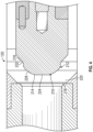
- FIG. 4 there is shown another non-limiting embodiment of a closure member 120 that may be used in conjunction with a flow control device 100.
- the Fig. 4 closure member 120 has a body 210 with an outer surface 212 defined by a composite geometry.
- the outer surface 212 extends along the circumference of the body 210.
- the closure member has a nose 214 and a base 216.
- the base 216 may have a linear surface aligned to seat along a contact line with an edge of a valve seat 218.
- the linear surface is circumferential to provide a contiguous line of contact.
- a fluid-tight seal which may be a metal-to-metal seal, occurs along such a contact line.
- the nose 214 may be formed using a geometry that allows the annular flow space 220 to increase in size slowly relative to the Fig. 2 closure member 20.
- the nose 214 has a juncture 222 with the base 216, an end face 224, and a concave outer surface 226 that connects the base 216 to the end face 224. It should be noted that by extending from the juncture 222 and terminating at the end face 224, the concave outer surface 226 from the majority, i.e., more than fifty percent, of the surface on the closure member 120 that defines an annular flow path 220. The concave outer surface 226 may follow a curve that forms a dome-like projection on the nose 214. Thus, in one aspect, the outer surface 226 is circumferential.
- the geometry of the curve defining the concave outer surface 224 may depend on a number of factors including, but not limited to, the dimensions of the components of the flow control device 100, the expected operating parameters, and properties of the flowing fluid. Generally speaking, the geometry may be selected to gradually increase an annular flow area 220 between the closure member 120 and the valve seat 218.
- the variable "m” may be a value between 0.0001 and 0.0200, a value between 0.0010 and 0.014, or a value between 0.0010 and 0.012.
- the value "n” may be a value between 1.1 and 5, a value between 2 and 4, or a value between 2.5 and 3.5.
- the flow parameter (e.g ., flow rate, pressure, etc.) of the fluid supplied to the upper section 102 reaches a value sufficient to generate a pressure against the closure member 120 that overcomes the biasing force of the biasing member 130.
- This may sometimes be referred to as the "crack open" pressure of the flow control device 100.
- the closure member 120 unseats and the fluid fills a cavity 149 next to the piston 138.
- the fluid pressure in the cavity 149 displaces the piston 138 and compresses the spring members 132.
- the movement of the piston 138 also activates the dampener 140, if present, which also resists the unseating movement.
- the shape of the closure device 120, and particularly the concave outer surface 224 controls the size of the annular flow space 220 such that the pressure differential across the flow control device 100 is high enough to prevent the closure member 120 from reversing the direction of axial movement and re-seating on the valve seat 218.
- teachings of the present disclosure may be used in any number of situations wherein it is desired to form a fluid tight seal along a flow path in a controlled manner. Some of these situations involve an arrangement wherein the fluid flow is used to maintain a flow control device in an open position and the interruption of fluid flow is used to initiate the closing of the fluid flow device. Described below is one non-limiting mode of operation.
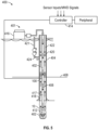
- a system 400 may use a flow control device 100 for controlling flow during dual gradient drilling.
- mud pumps on the sea floor may be used to supercharge the drilling fluid so that it returns against a higher geostatic pressure through the annulus/return lines to the surface (drilling platform or ship). This reduces the pressure gradient inside the well annulus, allowing very tight windows between formation fracture pressure and formation pore pressure to be used.
- Fig. 5 schematically shows a surface platform 401 from which a drill string 402 may be deployed to drill a wellbore 10.
- the drill string 402 may be disposed in a conduit formed of a riser 404 that extends from the platform 401 to the seabed 408.
- the drill string 402 may include a tubular member 408 that carries a bottomhole assembly (BHA) 412 at a distal end.
- BHA bottomhole assembly
- the tubular member which may be jointed tubulars or coiled tubing, is configured for use in the wellbore 10 (a wellbore tubular) and may include power and/or data conductors such as wires for providing bidirectional communication and power transmission ( e.g ., wired pipe).
- the conductors may be optical, metal, etc.
- Communication signals may also be transmitted by pressure pulses, acoustic signals, EM waves, RF waves, etc.
- a top drive (not shown), or other suitable rotary power source, may be utilized to rotate the drill string 402.
- a controller 414 may be placed at the surface for receiving and processing downhole data.
- the controller 414 may include a processor, a storage device for storing data and computer programs. The processor accesses the data and programs from the storage device and executes the instructions contained in the programs to control the drilling operations.
- the system 400 may include a fluid circulation system 416 that flows a drilling fluid into a bore 417 of the drill string 402. The fluid exits and returns to the riser 404 via an annulus 418.
- the riser 404 may include a restriction device 420 that diverts the fluid flowing in the annulus 418 to a flow cross line or a diverter line 421.
- a subsea pump 424 pumps the return fluid from the riser 404 to the surface via the diverter line 421.
- FIG. 5 further illustrates a material 422 having a lower density than the fluid in the annulus 418 in the riser 406 uphole of restriction device 420.
- the material 422 usually is seawater. However, a suitable fluid could have a density less or greater than seawater.
- the material 422 is used in providing a static pressure gradient to the wellbore that is less than the pressure gradient formed by the fluid downhole of the flow restriction device 420.
- fluid circulation system 416 maintains a continuous flow of fluid for the system 400.
- deactivating the fluid circulation system 416 does not immediately stop fluid circulation in the well because the density of the fluid in the bore 417 is greater than the density of the fluid in the annulus 418. That is, fluid in the bore 417 will continue to flow downward and out to the annulus 418 until the hydrostatic pressure in the bore 417 and the annulus 418 are the same. This is sometimes referred to as a "u-tube" effect.
- a flow control device 100 may be positioned along the drill string 402.
- the enclosure 101 ( Fig. 1A ,B ) may be configured to interconnect with the drill string 402.
- the operating set points of the fluid circulation system 416 e.g., flow rate / pressure
- the operating set points of the fluid circulation system 416 may be selected to maintain the flow control device 100 in an open position during normal operation.
- the flow control device 100 shifts to the closed position in a manner previously described, which blocks flow down the bore 417 by forming a fluid seal. Even though the hydrostatic pressure in the bore 417 may be greater than the hydrostatic pressure in the annulus 418, the closed fluid control device 100 prevents downward fluid flow.
Landscapes
- Engineering & Computer Science (AREA)
- General Engineering & Computer Science (AREA)
- Mechanical Engineering (AREA)
- Mining & Mineral Resources (AREA)
- Life Sciences & Earth Sciences (AREA)
- Geology (AREA)
- Fluid Mechanics (AREA)
- Environmental & Geological Engineering (AREA)
- Physics & Mathematics (AREA)
- General Life Sciences & Earth Sciences (AREA)
- Geochemistry & Mineralogy (AREA)
- Lift Valve (AREA)
- Pipe Accessories (AREA)
Description
- This disclosure relates generally to flow control devices.
- Fluid pathways and conduits employ a variety of devices in order to control fluid flow. One illustrative device is a valve that is used to block fluid flow across a fluid path way upon occurrence of a specified condition. These valves may sometimes be referred to as flow stop valves. In some configurations, a flow stop valve may be set to remain open to allow fluid flow during normal operation, but close when operation is interrupted. Such interruptions of fluid flow may cause transient conditions, e.g., pressure waves, which may damage the flow stop valve or may hinder the closing of the flow stop valve. Conventional flow stop valves use dampening arrangements to reduce cyclical impact between the valve cone and seat (or "chattering") during such transient conditions.
FromUS 2,670,922 a check valve comprising a housing, fluid flow openings, a valve seat on a plug, a ball, and a spring in said housing is known. The check valve eliminates excessive wear on the valve member when the fluid under pressure enters the valve.
Further, fromDE 20 2004 004609
US 4,817,739 refers to a valve which briefly interrupts the flow of fluid to bit jets to reduce the effective hydrostatic pressure at the drilling face. The valve comprises a piston, an upstream and downstream end, a sealing surface on said piston, and an annular surface, and at least one spring arranged to urge said piston toward a peripheral seat.
US 1,767,538 refers to a valve structure which is not liable to become clogged by material carried in suspension by the fluid flowing through a pipe. The valve comprises a chamber, a valve head and an annular valve seat at its upper end.
US 3,776,250 describes a valve apparatus which comprises a valve plunger in a valve body with the plunger opening against spring means. The plunger further comprises an elastomeric collar intermediately located on the plunger shaft for allowing to fill up a pipe string above a predetermined differential pressure.
US 5,501,280 refers to a casing filling and circulating apparatus which includes a flow passage therethrough and a check valve disposed within the flow passage for preventing spillage and for preventing fluid back-flow through the apparatus. Additionally, the apparatus includes a pressure relief seal means.
FromUS 2,148,850 a valve is known comprising a closure member and a deformable seal member, which makes wiping contact with an annular wall of the seat member. - The present disclosure provides a different approach to protecting valve components under such conditions.
- Disclosed is an apparatus for controlling flow of a fluid in a fluid conduit and a method for controlling flow of a fluid from a first section to a second section in a conduit as set forth in the independent claims.
- In aspects, the present disclosure provides an apparatus for controlling flow of a fluid in a fluid conduit. The apparatus includes a closure member having a cone body comprising a nose and a base, wherein the nose has an outer circumferential surface defined by a geometry different from a geometry defining an outer circumferential surface of the base; a biasing member applying a biasing force to the closure member; and a sealing member receiving the closure member, a fluid seal being formed in the fluid conduit when the biasing member presses the closure member against the sealing member, wherein the geometry of the outer circumferential surface of the cone body is designed to reduce a rate at which an annular flow space between the sealing member and the closure member increases while the closure member disengages and slides away from the sealing member, so that a pressure equalization is delayed, wherein the apparatus is configured to prevent the closure member from chattering.
- In aspects, the present disclosure further provides a method for controlling flow of a fluid from a first section to a second section in a conduit. The method includes enclosing the first section and the second section in an enclosure; forming a flow path conveying the fluid from the first section to the second section; positioning a sealing member, a biasing member, and a closure member in the second section and along a flow path of the flowing fluid; forming a fluid seal in the flow path when the biasing member presses the closure member against the sealing member, wherein the fluid seal blocks fluid flowing along the flow path from the first section to the second section; and applying a compressive force on the sealing member using a biasing member, wherein the closure member has a cone body comprising a nose and a base, wherein the nose has an outer circumferential surface defined by a geometry different from a geometry defining an outer circumferential surface of the base, wherein the geometry of the outer circumferential surface of the cone body is designed to reduce a rate at which an annular flow space between the sealing member and the closure member increases while the closure member disengages and slides away from the sealing member, so that a pressure equalization is delayed, wherein chattering of the closure member is prevented.
- For a detailed understanding of the present disclosure, reference should be made to the following detailed description of the embodiments, taken in conjunction with the accompanying drawings, in which like elements have been given like numerals, wherein:
-
FIGS. 1A-B sectionally illustrate a flow control device; -
FIG. 2 schematically illustrates a prior art valve cone; -
FIGS. 3A-C schematically illustrate non-limiting examples of valve cones made in accordance with the present invention; -
FIG. 4 schematically illustrates another non-limiting example of a valve cone in accordance with the present invention; and -
FIG. 5 schematically illustrates a dual gradient drilling system, which may employ flow control devices in accordance with the present invention. - In aspects, the present disclosure provides a flow control device for use in oil and gas well applications. One illustrative use of the flow control device is to stop the flow of a fluid, e.g., a drilling fluid, when a fluid mover (e.g., surface pumps) is stopped or deactivated. This may be a desirable function in dual gradient drilling (DGD) applications because such a flow control device can minimize a "u-tube" effect caused by equalizing the mud pressure between the inside of the drilling tubular and the return line. It may also be useful for keeping the drilling tubular filled with drilling fluid during connections in applications known as dynamic kill drilling (DKD) or riserless mud recovery (RMR). Illustrative embodiments of the present disclosure reduce the dynamic pressure loss across the flow control device by controlling the rate at which fluid passes between a valve cone and valve seat. Controlling this flow rate can delay pressure equalization across the flow control device and thereby prevent minimize valve cone chatter.
- Referring to
Fig. 1A-B, there is shown one embodiment of aflow control device 100 for controlling fluid flow along a conduit having an upper section 102 (Fig. 1A ) and a lower section 104 (Fig. 1B ). The flow control device may include anenclosure 101 that connects with the upper section 102 (Fig. 1A ) and the lower section 104 (Fig. 1B ); e.g., a threaded connection. In one arrangement, afluid 105 flows from theupper section 102 to thelower section 104. Theflow control device 100 may be configured to block this fluid flow upon the occurrence of one or more conditions. As used herein, the term "flow control device" may be a valve, choke, flow restrictor or other such device that can partially or completely block fluid flow along a path way. As used herein, the term fluid refers to liquids and mixtures that are mostly liquid (i.e., more than fifty percent liquid). - The
flow control device 100 may include aflow path 106 providing fluid communication between theupper section 102 and thelower section 104, asealing member 110, aclosure member 120, and abiasing member 130. In one embodiment, thebiasing member 130 may include spring members 132 (e.g., disk springs, leaf springs, coil springs, etc.) that surround and are supported on amandrel 134. Thesprings members 132 may be disposed between aretaining wall 136 and apiston 138 that is connected to themandrel 134. Optionally, theflow control device 100 may include a dampener 140 that is operatively connected to and controls the movement of theclosure member 120 during seating with or unseating from thesealing member 110. - The advantages of the present teachings may be illustrated by first describing a
conventional closure member 20, such as that shown inFig. 2 . Theconventional closure member 20 may be a cone having anouter surface 22 defined by a straight line; i.e., a linear surface. Initially, anarea 28 upstream of theclosure member 20 has a pressure higher than a pressure at anarea 30 downstream of theclosure member 20. When this differential pressure reaches a threshold value, the spring force of a biasing member (e.g., biasingmember 130 ofFig. 1A ) is overcome and theclosure member 20 unseats by moving axially away from avalve seat 24. - When the
conventional closure member 20 separates from thevalve seat 24, anannular flow area 26 between theconventional closure member 20 and thevalve seat 24 increases in size. This size increase allows a corresponding increase in fluid flow from theupstream area 28 to thedownstream area 30. This fluid flow can be sufficiently high enough to allow pressure equalization between theupstream area 28 anddownstream area 30, which then can cause theconventional closure member 20 to reseat due to the spring force. - Closure members, or valve cones, according to the present disclosure may be sized and shaped to control the rate at which the pressure differential across a flow control device decreases while the closure member disengages and slides away from a sealing member, such as a valve seat.
- Referring to
Figs. 3A-C, closure members 120 according to the present disclosure have a cone body defined by one or more surfaces configured to reduce the rate at which an annular flow space increases, which then delays pressure equalization. In these embodiments, theclosure member 120 seats against the sealingmember 110, which may be formed as a sleeve or ring-like member that has avalve seat 112. A fluid-tight seal, which may be a metal-to-metal seal, may be formed between theclosure member 120 and the sealingmember 110. -
Fig. 3A shows aclosure member 120 having a body with anouter surface 160 defined by a composite geometry that includes linear and curved surfaces. Theouter surface 160 extends around a circumference of theclosure member 120. The closure member has anose 162 and abase 164. The base 164 may have a linear surface aligned to seat against thevalve seat 112. - The
nose 162 may be formed using a geometry that allows theannular flow space 168 to increase in size slowly relative to theFig. 2 closure member 20. In one non-limiting embodiment, anouter surface 170 of thenose 162 follows a curve having a first end point at ajuncture 172 with thebase 164 and a second end point at or proximate to an apex 174 of thenose 162. Theouter surface 170 may be described as concave dome that projects from a straight line (not shown) that connects thejuncture 172 and the apex 174. In some embodiments, theouter surface 170 may be defined by a mathematical formula. It should be noted that the projectingcurved surface 170 creates a smaller cross-sectional flow area with theadjacent valve seat 112 between thejuncture 172 and the apex 174 as compared to theFig. 2 closure member 20. That is, thesurface 22 of the priorart valve cone 20 would not project from such a straight line. - It should be noted that the composite geometry is used principally along the surfaces of the
closure member 120 that defines the annular flow area. Thus, the surfaces defining this annular flow area are circumferential. Axially, this area is generally bounded at one end by a line of physical contact between theclosure member 120 and thevalve seat 112 and at the other end by the apex 174. -
Fig. 3B shows anotherclosure member 120 having a body with anouter surface 180 defined by a composite geometry having two straight lines with different slopes. The closure member has anose 182 and abase 184. The base 184 may be configured as thebase 164 ofFig. 3A . - The
nose 182 also uses a geometry that allows theannular flow space 188 to increase in size slowly relative to theFig. 2 closure member 20. In one non-limiting embodiment, an outer surface 189 of thenose 182 follows a straight line having a first end point at ajuncture 192 with thebase 184 and a second end point at or proximate to aface 194 of thenose 182. The slope of the line defining the outer surface 189 is less than the slope of the line defining the outer surface of thebase 184. The slopes are with reference to alongitudinal axis 198. It should be noted that, due to the relatively shallower slope, the outer surface 189 creates a smaller cross-sectional flow area between thejuncture 192 and theface 194 as compared to theFig. 2 closure member 20. -
Fig. 3C shows still anotherclosure member 120 having a body with anouter surface 200 defined by a composite geometry having one sloped line and one line parallel with thelongitudinal axis 198. The closure member has anose 202 and abase 204. The base 204 may be configured as thebase 164 ofFig. 3A . - The
nose 202 uses a geometry that varies the distance the fluid travels in an annular flow path in order to delay the loss of a pressure differential across theflow control device 100. Thenose 202 is formed as a cylinder that is separated from aninner surface 106 of the valve seat 208 by anannular flow space 210. In this arrangement, axial displacement of theclosure member 120 away from thevalve seat 112 reduces the axial distance the fluid travels through theannular flow space 210. Thus, while the size of the annular flow space does not substantially vary, flow resistance decreases as the distance the fluid travels decreases. - Referring now to
Fig. 4 , there is shown another non-limiting embodiment of aclosure member 120 that may be used in conjunction with aflow control device 100. TheFig. 4 closure member 120 has abody 210 with anouter surface 212 defined by a composite geometry. Theouter surface 212 extends along the circumference of thebody 210. The closure member has anose 214 and abase 216. The base 216 may have a linear surface aligned to seat along a contact line with an edge of avalve seat 218. In one aspect, the linear surface is circumferential to provide a contiguous line of contact. A fluid-tight seal, which may be a metal-to-metal seal, occurs along such a contact line. - The
nose 214 may be formed using a geometry that allows theannular flow space 220 to increase in size slowly relative to theFig. 2 closure member 20. In one non-limiting embodiment, thenose 214 has ajuncture 222 with thebase 216, anend face 224, and a concaveouter surface 226 that connects the base 216 to theend face 224. It should be noted that by extending from thejuncture 222 and terminating at theend face 224, the concaveouter surface 226 from the majority, i.e., more than fifty percent, of the surface on theclosure member 120 that defines anannular flow path 220. The concaveouter surface 226 may follow a curve that forms a dome-like projection on thenose 214. Thus, in one aspect, theouter surface 226 is circumferential. - The geometry of the curve defining the concave
outer surface 224 may depend on a number of factors including, but not limited to, the dimensions of the components of theflow control device 100, the expected operating parameters, and properties of the flowing fluid. Generally speaking, the geometry may be selected to gradually increase anannular flow area 220 between theclosure member 120 and thevalve seat 218. For some embodiments, the x, y coordinates of a curve defining theouter surface 224 may be defined by the formula: y = m xn. - The variable "m" may be a value between 0.0001 and 0.0200, a value between 0.0010 and 0.014, or a value between 0.0010 and 0.012. The value "n" may be a value between 1.1 and 5, a value between 2 and 4, or a value between 2.5 and 3.5.
- Referring to
Figs. 1A-B, in one mode of operation, the flow parameter (e.g., flow rate, pressure, etc.) of the fluid supplied to theupper section 102 reaches a value sufficient to generate a pressure against theclosure member 120 that overcomes the biasing force of the biasingmember 130. This may sometimes be referred to as the "crack open" pressure of theflow control device 100. Thus, theclosure member 120 unseats and the fluid fills acavity 149 next to thepiston 138. The fluid pressure in thecavity 149 displaces thepiston 138 and compresses thespring members 132. The movement of thepiston 138 also activates the dampener 140, if present, which also resists the unseating movement. - Referring to
Fig. 4 , advantageously, the shape of theclosure device 120, and particularly the concaveouter surface 224 controls the size of theannular flow space 220 such that the pressure differential across theflow control device 100 is high enough to prevent theclosure member 120 from reversing the direction of axial movement and re-seating on thevalve seat 218. - It should be appreciated that the teachings of the present disclosure may be used in any number of situations wherein it is desired to form a fluid tight seal along a flow path in a controlled manner. Some of these situations involve an arrangement wherein the fluid flow is used to maintain a flow control device in an open position and the interruption of fluid flow is used to initiate the closing of the fluid flow device. Described below is one non-limiting mode of operation.
- Referring now to
Fig. 5 , there is asystem 400 that may use aflow control device 100 for controlling flow during dual gradient drilling. In dual gradient applications, mud pumps on the sea floor may be used to supercharge the drilling fluid so that it returns against a higher geostatic pressure through the annulus/return lines to the surface (drilling platform or ship). This reduces the pressure gradient inside the well annulus, allowing very tight windows between formation fracture pressure and formation pore pressure to be used. -
Fig. 5 schematically shows asurface platform 401 from which adrill string 402 may be deployed to drill awellbore 10. Thedrill string 402 may be disposed in a conduit formed of ariser 404 that extends from theplatform 401 to theseabed 408. Thedrill string 402 may include atubular member 408 that carries a bottomhole assembly (BHA) 412 at a distal end. The tubular member, which may be jointed tubulars or coiled tubing, is configured for use in the wellbore 10 (a wellbore tubular) and may include power and/or data conductors such as wires for providing bidirectional communication and power transmission (e.g., wired pipe). The conductors may be optical, metal, etc. Communication signals may also be transmitted by pressure pulses, acoustic signals, EM waves, RF waves, etc. A top drive (not shown), or other suitable rotary power source, may be utilized to rotate thedrill string 402. Acontroller 414 may be placed at the surface for receiving and processing downhole data. Thecontroller 414 may include a processor, a storage device for storing data and computer programs. The processor accesses the data and programs from the storage device and executes the instructions contained in the programs to control the drilling operations. - The
system 400 may include afluid circulation system 416 that flows a drilling fluid into abore 417 of thedrill string 402. The fluid exits and returns to theriser 404 via anannulus 418. Theriser 404 may include arestriction device 420 that diverts the fluid flowing in theannulus 418 to a flow cross line or adiverter line 421. Asubsea pump 424 pumps the return fluid from theriser 404 to the surface via thediverter line 421.FIG. 5 further illustrates a material 422 having a lower density than the fluid in theannulus 418 in the riser 406 uphole ofrestriction device 420. Thematerial 422 usually is seawater. However, a suitable fluid could have a density less or greater than seawater. Thematerial 422 is used in providing a static pressure gradient to the wellbore that is less than the pressure gradient formed by the fluid downhole of theflow restriction device 420. - During drilling,
fluid circulation system 416 maintains a continuous flow of fluid for thesystem 400. However, deactivating thefluid circulation system 416 does not immediately stop fluid circulation in the well because the density of the fluid in thebore 417 is greater than the density of the fluid in theannulus 418. That is, fluid in thebore 417 will continue to flow downward and out to theannulus 418 until the hydrostatic pressure in thebore 417 and theannulus 418 are the same. This is sometimes referred to as a "u-tube" effect. - To maintain better control over fluid circulation in the
system 400, aflow control device 100 may be positioned along thedrill string 402. For example, the enclosure 101 (Fig. 1A ,B) may be configured to interconnect with thedrill string 402. The operating set points of the fluid circulation system 416 (e.g., flow rate / pressure) may be selected to maintain theflow control device 100 in an open position during normal operation. In the event that fluid circulation is interrupted, theflow control device 100 shifts to the closed position in a manner previously described, which blocks flow down thebore 417 by forming a fluid seal. Even though the hydrostatic pressure in thebore 417 may be greater than the hydrostatic pressure in theannulus 418, the closedfluid control device 100 prevents downward fluid flow.
Claims (9)
- An apparatus for controlling flow of a fluid in a fluid conduit, comprising:- a closure member (120) having a cone body comprising a nose (162, 182, 214) and a base (164, 184, 216), wherein the nose (162, 182, 214) has an outer circumferential surface defined by a geometry different from a geometry defining an outer circumferential surface of the base (164, 184, 216);- a biasing member (130) applying a biasing force to the closure member (120); and- a sealing member (110) receiving the closure member (120), a fluid seal being formed in the fluid conduit when the biasing member (130) presses the closure member (120) against the sealing member (110);wherein the geometry of the outer circumferential surface of the cone body is designed to reduce a rate at which an annular flow space between the sealing member (110) and the closure member (120) increases while the closure member (120) disengages and slides away from the sealing member (110), so that a pressure equalization is delayed, wherein the apparatus is configured to prevent the closure member from chattering.
- The apparatus of claim 1, wherein in axial direction of the closure member (120) the outer circumferential surface of the nose (162, 182, 214) has a curved geometry and the outer circumferential surface of the base (164, 184, 216) has a linearly sloped geometry.
- The apparatus of claim 1, wherein the outer circumferential surface of the nose (162, 182, 214) and the outer circumferential surface of the base (164, 184, 216) have each a linearly sloped geometry in axial direction of the closure member (120), wherein the slope of the nose (162, 182, 214) is less than the slope of the base (164, 184, 216).
- The apparatus of claim 1 or 2, wherein a physical line of contact is formed between the base (164, 184, 216) and the sealing member (110) when the closure member (120) is pressed against the sealing member (110).
- The apparatus of claim 4, when claim 4 is dependent on claim 2, wherein the base (164) joins the nose (162) at a juncture (172), wherein a fluid seal is along the physical line of contact when the biasing member (130) presses the closure member (120) against the sealing member (110).
- The apparatus of claim 5, wherein the nose (162, 182, 214) further includes an end face (224) and wherein the curved outer circumferential surface of the nose (162, 182, 214) terminates at the end face (224).
- A method for controlling flow of a fluid from a first section to a second section in a conduit, comprising:- enclosing the first section and the second section in an enclosure;- forming a flow path conveying the fluid from the first section to the second section;- positioning a sealing member (110), a biasing member (130), and a closure member (120) in the second section and along a flow path of the flowing fluid;- forming a fluid seal in the flow path when the biasing member (130) presses the closure member (120) against the sealing member (110), wherein the fluid seal blocks fluid flowing along the flow path from the first section to the second section; and- applying a compressive force on the sealing member (110) using a biasing member (130),wherein the closure member (120) has a cone body comprising a nose (162, 182, 202, 214) and a base (164, 184, 204, 216), wherein the nose (162, 182, 202, 214) has an outer circumferential surface defined by a geometry different from a geometry defining an outer circumferential surface of the base (164, 184, 204, 216),wherein the geometry of the outer circumferential surface of the cone body is designed to reduce a rate at which an annular flow space between the sealing member (110) and the closure member (120) increases while the closure member (120) disengages andslides away from the sealing member (110), so that a pressure equalization is delayed, wherein chattering of the closure member is prevented.
- The method of claim 7, wherein in axial direction of the closure member (120) the outer circumferential surface of the nose (162, 182, 214) has a curved geometry and the outer circumferential surface of the base (164, 184, 216)) has a linearly sloped geometry.
- The method of claim 7, wherein the outer circumferential surface of the nose (162, 182, 214) and the outer circumferential surface of the base (164, 184, 216) have each a linearly sloped geometry in axial direction of the closure member (120), wherein the slope of the nose (162, 182, 214) is less than the slope of the base (164, 184, 216).
Applications Claiming Priority (2)
| Application Number | Priority Date | Filing Date | Title |
|---|---|---|---|
| US14/976,690 US10302223B2 (en) | 2015-12-21 | 2015-12-21 | Anti-chattering valve cone and methods for using same |
| PCT/US2016/067848 WO2017112699A2 (en) | 2015-12-21 | 2016-12-20 | Anti-chattering valve cone and methods for using same |
Publications (3)
| Publication Number | Publication Date |
|---|---|
| EP3394388A2 EP3394388A2 (en) | 2018-10-31 |
| EP3394388A4 EP3394388A4 (en) | 2019-08-28 |
| EP3394388B1 true EP3394388B1 (en) | 2024-09-11 |
Family
ID=59066082
Family Applications (1)
| Application Number | Title | Priority Date | Filing Date |
|---|---|---|---|
| EP16879987.2A Active EP3394388B1 (en) | 2015-12-21 | 2016-12-20 | Anti-chattering valve cone and methods for using same |
Country Status (3)
| Country | Link |
|---|---|
| US (1) | US10302223B2 (en) |
| EP (1) | EP3394388B1 (en) |
| WO (1) | WO2017112699A2 (en) |
Families Citing this family (2)
| Publication number | Priority date | Publication date | Assignee | Title |
|---|---|---|---|---|
| CN111814100B (en) * | 2020-08-06 | 2021-03-19 | 西南石油大学 | Method for dynamically simulating circulating temperature change of marine subsea pump lifting drilling system without marine riser |
| CN115370754B (en) * | 2021-05-17 | 2025-09-23 | 丹佛斯有限公司 | flow control valve |
Citations (5)
| Publication number | Priority date | Publication date | Assignee | Title |
|---|---|---|---|---|
| US2148850A (en) * | 1931-12-19 | 1939-02-28 | Macclatchie Mfg Company | Mud pump valve |
| US3776250A (en) * | 1972-04-13 | 1973-12-04 | Halliburton Co | Float collar with differential fill feature |
| US4622993A (en) * | 1986-02-20 | 1986-11-18 | Taylor Julian S | Well pipe float valve |
| US5501280A (en) * | 1994-10-27 | 1996-03-26 | Halliburton Company | Casing filling and circulating apparatus and method |
| DE202004004609U1 (en) * | 2004-03-24 | 2004-07-29 | Trw Automotive Gmbh | Pressure relief valve |
Family Cites Families (23)
| Publication number | Priority date | Publication date | Assignee | Title |
|---|---|---|---|---|
| US1767538A (en) | 1928-06-11 | 1930-06-24 | Nat Supply Co | Back-pressure valve for drill pipes |
| US2670922A (en) * | 1951-04-07 | 1954-03-02 | Macco Oil Tool Company Inc | Check valve |
| US2730125A (en) | 1952-04-16 | 1956-01-10 | Gen Motors Corp | Filter valve with deflector |
| US3145732A (en) | 1962-08-27 | 1964-08-25 | Spartan Hydraulics Inc | Hydraulic pressure relief valve |
| DE2402774A1 (en) | 1974-01-22 | 1975-07-31 | Leibnitz Bodo | Noise absorber for high speed flow valves - is made from sintered ceramics as a cylindrical lining |
| US4817739A (en) | 1986-06-23 | 1989-04-04 | Jeter John D | Drilling enhancement tool |
| SE465533B (en) | 1990-02-19 | 1991-09-23 | Saab Automobile | SILENT BACK VALVE FOR PULSING FLOW |
| DE19754257A1 (en) | 1997-12-06 | 1999-06-10 | Bosch Gmbh Robert | Solenoid valve for a liquid-controlled heating and / or cooling system |
| DE19800496A1 (en) | 1998-01-09 | 1999-07-15 | Itt Mfg Enterprises Inc | Pressure control valve, in particular for controlling the pressure medium in slip. hydrl. Braking systems |
| US6640897B1 (en) * | 1999-09-10 | 2003-11-04 | Bj Services Company | Method and apparatus for through tubing gravel packing, cleaning and lifting |
| DE10160970A1 (en) | 2001-12-11 | 2003-06-18 | Bosch Gmbh Robert | Valve, especially for liquid-regulated vehicle heating and/or cooling system, has damping element(s) that reduces lifting rod speed when closing valve, simultaneously acts as valve element |
| DE10204269A1 (en) | 2002-02-02 | 2003-08-07 | Bosch Gmbh Robert | Pressure regulator for a fuel supply system of an internal combustion engine |
| DE10224682A1 (en) | 2002-06-04 | 2003-12-18 | Bosch Gmbh Robert | Pressure regulator for a fuel supply system of an internal combustion engine |
| DE10321154A1 (en) | 2003-05-12 | 2004-12-02 | Robert Bosch Gmbh | Valve |
| DE10343940A1 (en) | 2003-09-23 | 2005-04-14 | Robert Bosch Gmbh | Magnetic valve, in particular for a liquid-regulated heating and/or cooling installation incorporates a damping disk which is located in the gap between the face of the guide sleeve and the shoulder of the coil unit |
| GB0910143D0 (en) * | 2009-06-12 | 2009-07-29 | Welltools Ltd | Controlled debris removal system |
| EP2547857B1 (en) * | 2010-03-19 | 2018-09-12 | Noetic Technologies Inc. | Casing fill-up fluid management tool |
| US20110266472A1 (en) | 2010-04-28 | 2011-11-03 | Larry Rayner Russell | Self piloted check valve |
| US9243464B2 (en) * | 2011-02-10 | 2016-01-26 | Baker Hughes Incorporated | Flow control device and methods for using same |
| JP5708515B2 (en) | 2012-01-31 | 2015-04-30 | 株式会社デンソー | Check valve |
| US9255646B2 (en) | 2013-06-28 | 2016-02-09 | Air Products And Chemicals, Inc. | Excess flow shutoff valve |
| MX2016006283A (en) * | 2014-01-15 | 2016-07-26 | Halliburton Energy Services Inc | Method and apparatus for retaining weighted fluid in a tubular section. |
| WO2015130762A1 (en) * | 2014-02-26 | 2015-09-03 | M-I Drilling Fluids U.K. Ltd. | System and method for flow diversion |
-
2015
- 2015-12-21 US US14/976,690 patent/US10302223B2/en active Active
-
2016
- 2016-12-20 WO PCT/US2016/067848 patent/WO2017112699A2/en not_active Ceased
- 2016-12-20 EP EP16879987.2A patent/EP3394388B1/en active Active
Patent Citations (5)
| Publication number | Priority date | Publication date | Assignee | Title |
|---|---|---|---|---|
| US2148850A (en) * | 1931-12-19 | 1939-02-28 | Macclatchie Mfg Company | Mud pump valve |
| US3776250A (en) * | 1972-04-13 | 1973-12-04 | Halliburton Co | Float collar with differential fill feature |
| US4622993A (en) * | 1986-02-20 | 1986-11-18 | Taylor Julian S | Well pipe float valve |
| US5501280A (en) * | 1994-10-27 | 1996-03-26 | Halliburton Company | Casing filling and circulating apparatus and method |
| DE202004004609U1 (en) * | 2004-03-24 | 2004-07-29 | Trw Automotive Gmbh | Pressure relief valve |
Also Published As
| Publication number | Publication date |
|---|---|
| EP3394388A2 (en) | 2018-10-31 |
| EP3394388A4 (en) | 2019-08-28 |
| US10302223B2 (en) | 2019-05-28 |
| WO2017112699A2 (en) | 2017-06-29 |
| US20170175929A1 (en) | 2017-06-22 |
| WO2017112699A3 (en) | 2018-02-22 |
Similar Documents
| Publication | Publication Date | Title |
|---|---|---|
| US9243464B2 (en) | Flow control device and methods for using same | |
| US6655405B2 (en) | BOP operating system with quick dump valve | |
| US8590629B2 (en) | Flow stop valve and method | |
| US10190397B2 (en) | Closure device for a surge pressure reduction tool | |
| CA2771350A1 (en) | Self aligning mud saver valve seat | |
| US11649695B2 (en) | Pressure regulating check valve | |
| BR112016009779B1 (en) | SUBSEA DRILLING SYSTEM AND FLUID SYSTEM FOR A SUBSEA DRILLING SYSTEM | |
| CN101382054A (en) | Nozzle valve | |
| WO2013055226A1 (en) | Device and method for controlling return flow from a bore hole | |
| CN108915660A (en) | A fracturing method for coiled tubing with internal blowout prevention function | |
| CN102007265A (en) | Pressure control system | |
| US10138695B2 (en) | Downhole fluid flow diverting | |
| US10302223B2 (en) | Anti-chattering valve cone and methods for using same | |
| AU2009351364B2 (en) | Flow stop valve | |
| US10077632B2 (en) | Pilot inside a ball suitable for wellbore drilling operations | |
| US20230075775A1 (en) | Automatic choking hydraulic shock reduction valve | |
| US20120061094A1 (en) | Ball-seat apparatus and method | |
| US20110303422A1 (en) | Low impact ball-seat apparatus and method | |
| EP3362638B1 (en) | Pilot inside a ball suitable for wellbore operations |
Legal Events
| Date | Code | Title | Description |
|---|---|---|---|
| STAA | Information on the status of an ep patent application or granted ep patent |
Free format text: STATUS: THE INTERNATIONAL PUBLICATION HAS BEEN MADE |
|
| PUAI | Public reference made under article 153(3) epc to a published international application that has entered the european phase |
Free format text: ORIGINAL CODE: 0009012 |
|
| STAA | Information on the status of an ep patent application or granted ep patent |
Free format text: STATUS: REQUEST FOR EXAMINATION WAS MADE |
|
| 17P | Request for examination filed |
Effective date: 20180720 |
|
| AK | Designated contracting states |
Kind code of ref document: A2 Designated state(s): AL AT BE BG CH CY CZ DE DK EE ES FI FR GB GR HR HU IE IS IT LI LT LU LV MC MK MT NL NO PL PT RO RS SE SI SK SM TR |
|
| AX | Request for extension of the european patent |
Extension state: BA ME |
|
| DAV | Request for validation of the european patent (deleted) | ||
| DAX | Request for extension of the european patent (deleted) | ||
| A4 | Supplementary search report drawn up and despatched |
Effective date: 20190725 |
|
| RIC1 | Information provided on ipc code assigned before grant |
Ipc: F16K 17/04 20060101ALI20190719BHEP Ipc: E21B 21/10 20060101ALI20190719BHEP Ipc: E21B 34/06 20060101AFI20190719BHEP Ipc: F16K 1/54 20060101ALI20190719BHEP Ipc: F16K 1/36 20060101ALI20190719BHEP Ipc: F16K 1/42 20060101ALI20190719BHEP |
|
| STAA | Information on the status of an ep patent application or granted ep patent |
Free format text: STATUS: EXAMINATION IS IN PROGRESS |
|
| 17Q | First examination report despatched |
Effective date: 20220104 |
|
| P01 | Opt-out of the competence of the unified patent court (upc) registered |
Effective date: 20230526 |
|
| GRAP | Despatch of communication of intention to grant a patent |
Free format text: ORIGINAL CODE: EPIDOSNIGR1 |
|
| STAA | Information on the status of an ep patent application or granted ep patent |
Free format text: STATUS: GRANT OF PATENT IS INTENDED |
|
| INTG | Intention to grant announced |
Effective date: 20240321 |
|
| RIN1 | Information on inventor provided before grant (corrected) |
Inventor name: SIMANOWSKI, MARIO Inventor name: CANELLA, DONALD J., JR. Inventor name: FUHST, KARSTEN |
|
| GRAS | Grant fee paid |
Free format text: ORIGINAL CODE: EPIDOSNIGR3 |
|
| RAP3 | Party data changed (applicant data changed or rights of an application transferred) |
Owner name: BAKER HUGHES HOLDINGS LLC |
|
| GRAA | (expected) grant |
Free format text: ORIGINAL CODE: 0009210 |
|
| STAA | Information on the status of an ep patent application or granted ep patent |
Free format text: STATUS: THE PATENT HAS BEEN GRANTED |
|
| AK | Designated contracting states |
Kind code of ref document: B1 Designated state(s): AL AT BE BG CH CY CZ DE DK EE ES FI FR GB GR HR HU IE IS IT LI LT LU LV MC MK MT NL NO PL PT RO RS SE SI SK SM TR |
|
| REG | Reference to a national code |
Ref country code: GB Ref legal event code: FG4D |
|
| REG | Reference to a national code |
Ref country code: CH Ref legal event code: EP |
|
| REG | Reference to a national code |
Ref country code: DE Ref legal event code: R096 Ref document number: 602016089394 Country of ref document: DE |
|
| REG | Reference to a national code |
Ref country code: IE Ref legal event code: FG4D |
|
| REG | Reference to a national code |
Ref country code: LT Ref legal event code: MG9D |
|
| REG | Reference to a national code |
Ref country code: NL Ref legal event code: MP Effective date: 20240911 |
|
| PG25 | Lapsed in a contracting state [announced via postgrant information from national office to epo] |
Ref country code: GR Free format text: LAPSE BECAUSE OF FAILURE TO SUBMIT A TRANSLATION OF THE DESCRIPTION OR TO PAY THE FEE WITHIN THE PRESCRIBED TIME-LIMIT Effective date: 20241212 Ref country code: FI Free format text: LAPSE BECAUSE OF FAILURE TO SUBMIT A TRANSLATION OF THE DESCRIPTION OR TO PAY THE FEE WITHIN THE PRESCRIBED TIME-LIMIT Effective date: 20240911 |
|
| PG25 | Lapsed in a contracting state [announced via postgrant information from national office to epo] |
Ref country code: BG Free format text: LAPSE BECAUSE OF FAILURE TO SUBMIT A TRANSLATION OF THE DESCRIPTION OR TO PAY THE FEE WITHIN THE PRESCRIBED TIME-LIMIT Effective date: 20240911 |
|
| PG25 | Lapsed in a contracting state [announced via postgrant information from national office to epo] |
Ref country code: LV Free format text: LAPSE BECAUSE OF FAILURE TO SUBMIT A TRANSLATION OF THE DESCRIPTION OR TO PAY THE FEE WITHIN THE PRESCRIBED TIME-LIMIT Effective date: 20240911 |
|
| PG25 | Lapsed in a contracting state [announced via postgrant information from national office to epo] |
Ref country code: HR Free format text: LAPSE BECAUSE OF FAILURE TO SUBMIT A TRANSLATION OF THE DESCRIPTION OR TO PAY THE FEE WITHIN THE PRESCRIBED TIME-LIMIT Effective date: 20240911 |
|
| PG25 | Lapsed in a contracting state [announced via postgrant information from national office to epo] |
Ref country code: RS Free format text: LAPSE BECAUSE OF FAILURE TO SUBMIT A TRANSLATION OF THE DESCRIPTION OR TO PAY THE FEE WITHIN THE PRESCRIBED TIME-LIMIT Effective date: 20241211 Ref country code: ES Free format text: LAPSE BECAUSE OF FAILURE TO SUBMIT A TRANSLATION OF THE DESCRIPTION OR TO PAY THE FEE WITHIN THE PRESCRIBED TIME-LIMIT Effective date: 20240911 |
|
| PG25 | Lapsed in a contracting state [announced via postgrant information from national office to epo] |
Ref country code: RS Free format text: LAPSE BECAUSE OF FAILURE TO SUBMIT A TRANSLATION OF THE DESCRIPTION OR TO PAY THE FEE WITHIN THE PRESCRIBED TIME-LIMIT Effective date: 20241211 Ref country code: LV Free format text: LAPSE BECAUSE OF FAILURE TO SUBMIT A TRANSLATION OF THE DESCRIPTION OR TO PAY THE FEE WITHIN THE PRESCRIBED TIME-LIMIT Effective date: 20240911 Ref country code: HR Free format text: LAPSE BECAUSE OF FAILURE TO SUBMIT A TRANSLATION OF THE DESCRIPTION OR TO PAY THE FEE WITHIN THE PRESCRIBED TIME-LIMIT Effective date: 20240911 Ref country code: GR Free format text: LAPSE BECAUSE OF FAILURE TO SUBMIT A TRANSLATION OF THE DESCRIPTION OR TO PAY THE FEE WITHIN THE PRESCRIBED TIME-LIMIT Effective date: 20241212 Ref country code: FI Free format text: LAPSE BECAUSE OF FAILURE TO SUBMIT A TRANSLATION OF THE DESCRIPTION OR TO PAY THE FEE WITHIN THE PRESCRIBED TIME-LIMIT Effective date: 20240911 Ref country code: ES Free format text: LAPSE BECAUSE OF FAILURE TO SUBMIT A TRANSLATION OF THE DESCRIPTION OR TO PAY THE FEE WITHIN THE PRESCRIBED TIME-LIMIT Effective date: 20240911 Ref country code: BG Free format text: LAPSE BECAUSE OF FAILURE TO SUBMIT A TRANSLATION OF THE DESCRIPTION OR TO PAY THE FEE WITHIN THE PRESCRIBED TIME-LIMIT Effective date: 20240911 |
|
| REG | Reference to a national code |
Ref country code: AT Ref legal event code: MK05 Ref document number: 1722836 Country of ref document: AT Kind code of ref document: T Effective date: 20240911 |
|
| PG25 | Lapsed in a contracting state [announced via postgrant information from national office to epo] |
Ref country code: NL Free format text: LAPSE BECAUSE OF FAILURE TO SUBMIT A TRANSLATION OF THE DESCRIPTION OR TO PAY THE FEE WITHIN THE PRESCRIBED TIME-LIMIT Effective date: 20240911 |
|
| PG25 | Lapsed in a contracting state [announced via postgrant information from national office to epo] |
Ref country code: PT Free format text: LAPSE BECAUSE OF FAILURE TO SUBMIT A TRANSLATION OF THE DESCRIPTION OR TO PAY THE FEE WITHIN THE PRESCRIBED TIME-LIMIT Effective date: 20250113 Ref country code: IS Free format text: LAPSE BECAUSE OF FAILURE TO SUBMIT A TRANSLATION OF THE DESCRIPTION OR TO PAY THE FEE WITHIN THE PRESCRIBED TIME-LIMIT Effective date: 20250111 |
|
| PG25 | Lapsed in a contracting state [announced via postgrant information from national office to epo] |
Ref country code: RO Free format text: LAPSE BECAUSE OF FAILURE TO SUBMIT A TRANSLATION OF THE DESCRIPTION OR TO PAY THE FEE WITHIN THE PRESCRIBED TIME-LIMIT Effective date: 20240911 Ref country code: SM Free format text: LAPSE BECAUSE OF FAILURE TO SUBMIT A TRANSLATION OF THE DESCRIPTION OR TO PAY THE FEE WITHIN THE PRESCRIBED TIME-LIMIT Effective date: 20240911 |
|
| PG25 | Lapsed in a contracting state [announced via postgrant information from national office to epo] |
Ref country code: EE Free format text: LAPSE BECAUSE OF FAILURE TO SUBMIT A TRANSLATION OF THE DESCRIPTION OR TO PAY THE FEE WITHIN THE PRESCRIBED TIME-LIMIT Effective date: 20240911 Ref country code: AT Free format text: LAPSE BECAUSE OF FAILURE TO SUBMIT A TRANSLATION OF THE DESCRIPTION OR TO PAY THE FEE WITHIN THE PRESCRIBED TIME-LIMIT Effective date: 20240911 |
|
| PG25 | Lapsed in a contracting state [announced via postgrant information from national office to epo] |
Ref country code: CZ Free format text: LAPSE BECAUSE OF FAILURE TO SUBMIT A TRANSLATION OF THE DESCRIPTION OR TO PAY THE FEE WITHIN THE PRESCRIBED TIME-LIMIT Effective date: 20240911 Ref country code: PL Free format text: LAPSE BECAUSE OF FAILURE TO SUBMIT A TRANSLATION OF THE DESCRIPTION OR TO PAY THE FEE WITHIN THE PRESCRIBED TIME-LIMIT Effective date: 20240911 |
|
| PG25 | Lapsed in a contracting state [announced via postgrant information from national office to epo] |
Ref country code: SK Free format text: LAPSE BECAUSE OF FAILURE TO SUBMIT A TRANSLATION OF THE DESCRIPTION OR TO PAY THE FEE WITHIN THE PRESCRIBED TIME-LIMIT Effective date: 20240911 Ref country code: IT Free format text: LAPSE BECAUSE OF FAILURE TO SUBMIT A TRANSLATION OF THE DESCRIPTION OR TO PAY THE FEE WITHIN THE PRESCRIBED TIME-LIMIT Effective date: 20240911 |
|
| REG | Reference to a national code |
Ref country code: DE Ref legal event code: R097 Ref document number: 602016089394 Country of ref document: DE |
|
| REG | Reference to a national code |
Ref country code: DE Ref legal event code: R119 Ref document number: 602016089394 Country of ref document: DE |
|
| PG25 | Lapsed in a contracting state [announced via postgrant information from national office to epo] |
Ref country code: MC Free format text: LAPSE BECAUSE OF FAILURE TO SUBMIT A TRANSLATION OF THE DESCRIPTION OR TO PAY THE FEE WITHIN THE PRESCRIBED TIME-LIMIT Effective date: 20240911 |
|
| PG25 | Lapsed in a contracting state [announced via postgrant information from national office to epo] |
Ref country code: DK Free format text: LAPSE BECAUSE OF FAILURE TO SUBMIT A TRANSLATION OF THE DESCRIPTION OR TO PAY THE FEE WITHIN THE PRESCRIBED TIME-LIMIT Effective date: 20240911 |
|
| PLBE | No opposition filed within time limit |
Free format text: ORIGINAL CODE: 0009261 |
|
| STAA | Information on the status of an ep patent application or granted ep patent |
Free format text: STATUS: NO OPPOSITION FILED WITHIN TIME LIMIT |
|
| REG | Reference to a national code |
Ref country code: CH Ref legal event code: PL |
|
| PG25 | Lapsed in a contracting state [announced via postgrant information from national office to epo] |
Ref country code: LU Free format text: LAPSE BECAUSE OF NON-PAYMENT OF DUE FEES Effective date: 20241220 |
|
| 26N | No opposition filed |
Effective date: 20250612 |
|
| PG25 | Lapsed in a contracting state [announced via postgrant information from national office to epo] |
Ref country code: SE Free format text: LAPSE BECAUSE OF FAILURE TO SUBMIT A TRANSLATION OF THE DESCRIPTION OR TO PAY THE FEE WITHIN THE PRESCRIBED TIME-LIMIT Effective date: 20240911 |
|
| REG | Reference to a national code |
Ref country code: BE Ref legal event code: MM Effective date: 20241231 |
|
| PG25 | Lapsed in a contracting state [announced via postgrant information from national office to epo] |
Ref country code: DE Free format text: LAPSE BECAUSE OF NON-PAYMENT OF DUE FEES Effective date: 20250701 |
|
| PG25 | Lapsed in a contracting state [announced via postgrant information from national office to epo] |
Ref country code: BE Free format text: LAPSE BECAUSE OF NON-PAYMENT OF DUE FEES Effective date: 20241231 |
|
| PG25 | Lapsed in a contracting state [announced via postgrant information from national office to epo] |
Ref country code: FR Free format text: LAPSE BECAUSE OF NON-PAYMENT OF DUE FEES Effective date: 20241231 |
|
| PG25 | Lapsed in a contracting state [announced via postgrant information from national office to epo] |
Ref country code: CH Free format text: LAPSE BECAUSE OF NON-PAYMENT OF DUE FEES Effective date: 20241231 |
|
| PG25 | Lapsed in a contracting state [announced via postgrant information from national office to epo] |
Ref country code: IE Free format text: LAPSE BECAUSE OF NON-PAYMENT OF DUE FEES Effective date: 20241220 |
|
| PGFP | Annual fee paid to national office [announced via postgrant information from national office to epo] |
Ref country code: GB Payment date: 20251119 Year of fee payment: 10 |
|
| PGFP | Annual fee paid to national office [announced via postgrant information from national office to epo] |
Ref country code: NO Payment date: 20251121 Year of fee payment: 10 |