EP3394240B1 - Improvements in and relating to cell harvesting apparatus - Google Patents
Improvements in and relating to cell harvesting apparatus Download PDFInfo
- Publication number
- EP3394240B1 EP3394240B1 EP16825753.3A EP16825753A EP3394240B1 EP 3394240 B1 EP3394240 B1 EP 3394240B1 EP 16825753 A EP16825753 A EP 16825753A EP 3394240 B1 EP3394240 B1 EP 3394240B1
- Authority
- EP
- European Patent Office
- Prior art keywords
- fluid
- kit
- frame
- cells
- paths
- Prior art date
- Legal status (The legal status is an assumption and is not a legal conclusion. Google has not performed a legal analysis and makes no representation as to the accuracy of the status listed.)
- Active
Links
Images







Classifications
-
- C—CHEMISTRY; METALLURGY
- C12—BIOCHEMISTRY; BEER; SPIRITS; WINE; VINEGAR; MICROBIOLOGY; ENZYMOLOGY; MUTATION OR GENETIC ENGINEERING
- C12M—APPARATUS FOR ENZYMOLOGY OR MICROBIOLOGY; APPARATUS FOR CULTURING MICROORGANISMS FOR PRODUCING BIOMASS, FOR GROWING CELLS OR FOR OBTAINING FERMENTATION OR METABOLIC PRODUCTS, i.e. BIOREACTORS OR FERMENTERS
- C12M1/00—Apparatus for enzymology or microbiology
- C12M1/26—Inoculator or sampler
-
- A—HUMAN NECESSITIES
- A61—MEDICAL OR VETERINARY SCIENCE; HYGIENE
- A61M—DEVICES FOR INTRODUCING MEDIA INTO, OR ONTO, THE BODY; DEVICES FOR TRANSDUCING BODY MEDIA OR FOR TAKING MEDIA FROM THE BODY; DEVICES FOR PRODUCING OR ENDING SLEEP OR STUPOR
- A61M1/00—Suction or pumping devices for medical purposes; Devices for carrying-off, for treatment of, or for carrying-over, body-liquids; Drainage systems
- A61M1/02—Blood transfusion apparatus
- A61M1/0281—Apparatus for treatment of blood or blood constituents prior to transfusion, e.g. washing, filtering or thawing
-
- B—PERFORMING OPERATIONS; TRANSPORTING
- B01—PHYSICAL OR CHEMICAL PROCESSES OR APPARATUS IN GENERAL
- B01L—CHEMICAL OR PHYSICAL LABORATORY APPARATUS FOR GENERAL USE
- B01L3/00—Containers or dishes for laboratory use, e.g. laboratory glassware; Droppers
- B01L3/50—Containers for the purpose of retaining a material to be analysed, e.g. test tubes
- B01L3/502—Containers for the purpose of retaining a material to be analysed, e.g. test tubes with fluid transport, e.g. in multi-compartment structures
- B01L3/5027—Containers for the purpose of retaining a material to be analysed, e.g. test tubes with fluid transport, e.g. in multi-compartment structures by integrated microfluidic structures, i.e. dimensions of channels and chambers are such that surface tension forces are important, e.g. lab-on-a-chip
- B01L3/50273—Containers for the purpose of retaining a material to be analysed, e.g. test tubes with fluid transport, e.g. in multi-compartment structures by integrated microfluidic structures, i.e. dimensions of channels and chambers are such that surface tension forces are important, e.g. lab-on-a-chip characterised by the means or forces applied to move the fluids
-
- C—CHEMISTRY; METALLURGY
- C12—BIOCHEMISTRY; BEER; SPIRITS; WINE; VINEGAR; MICROBIOLOGY; ENZYMOLOGY; MUTATION OR GENETIC ENGINEERING
- C12M—APPARATUS FOR ENZYMOLOGY OR MICROBIOLOGY; APPARATUS FOR CULTURING MICROORGANISMS FOR PRODUCING BIOMASS, FOR GROWING CELLS OR FOR OBTAINING FERMENTATION OR METABOLIC PRODUCTS, i.e. BIOREACTORS OR FERMENTERS
- C12M33/00—Means for introduction, transport, positioning, extraction, harvesting, peeling or sampling of biological material in or from the apparatus
- C12M33/14—Means for introduction, transport, positioning, extraction, harvesting, peeling or sampling of biological material in or from the apparatus with filters, sieves or membranes
-
- C—CHEMISTRY; METALLURGY
- C12—BIOCHEMISTRY; BEER; SPIRITS; WINE; VINEGAR; MICROBIOLOGY; ENZYMOLOGY; MUTATION OR GENETIC ENGINEERING
- C12M—APPARATUS FOR ENZYMOLOGY OR MICROBIOLOGY; APPARATUS FOR CULTURING MICROORGANISMS FOR PRODUCING BIOMASS, FOR GROWING CELLS OR FOR OBTAINING FERMENTATION OR METABOLIC PRODUCTS, i.e. BIOREACTORS OR FERMENTERS
- C12M47/00—Means for after-treatment of the produced biomass or of the fermentation or metabolic products, e.g. storage of biomass
- C12M47/02—Separating microorganisms from the culture medium; Concentration of biomass
-
- A—HUMAN NECESSITIES
- A61—MEDICAL OR VETERINARY SCIENCE; HYGIENE
- A61M—DEVICES FOR INTRODUCING MEDIA INTO, OR ONTO, THE BODY; DEVICES FOR TRANSDUCING BODY MEDIA OR FOR TAKING MEDIA FROM THE BODY; DEVICES FOR PRODUCING OR ENDING SLEEP OR STUPOR
- A61M2205/00—General characteristics of the apparatus
- A61M2205/12—General characteristics of the apparatus with interchangeable cassettes forming partially or totally the fluid circuit
- A61M2205/123—General characteristics of the apparatus with interchangeable cassettes forming partially or totally the fluid circuit with incorporated reservoirs
-
- A—HUMAN NECESSITIES
- A61—MEDICAL OR VETERINARY SCIENCE; HYGIENE
- A61M—DEVICES FOR INTRODUCING MEDIA INTO, OR ONTO, THE BODY; DEVICES FOR TRANSDUCING BODY MEDIA OR FOR TAKING MEDIA FROM THE BODY; DEVICES FOR PRODUCING OR ENDING SLEEP OR STUPOR
- A61M2205/00—General characteristics of the apparatus
- A61M2205/12—General characteristics of the apparatus with interchangeable cassettes forming partially or totally the fluid circuit
- A61M2205/125—General characteristics of the apparatus with interchangeable cassettes forming partially or totally the fluid circuit with incorporated filters
Definitions
- This invention relates to cell harvesting apparatus, to the improved functioning of such apparatus, and to improvements in the components thereof.
- therapeutic applications such as cell therapy, or tissue engineering.
- therapeutic applications include but are not limited to autologous or allogeneic transplantation of stem cells, transplantation of matured functional cells, T cells, modified human cells including T cells, or xenotransplantation of non-human cells.
- the applications facilitate healing of the damaged tissue or an organ, by regenerating cells to improve the condition of a diseased state.
- cryo-preserved cells For translational research, which facilitates the development and implementation of scientific discoveries to prevent, diagnose, and treat disease using state-of-the-art technologies, a range of potential cell types require isolation prior to modification, activation, and/or expansion. To meet this translational market need, the cells are first required to be concentrated and washed to remove any impurities.
- MNC mononucleated cells
- DMSO dimethylsulfoxide
- the cells need to be washed, typically through a dilution process, several times to minimize the preservative's concentration before re-concentrating and re-suspending the cells for use. Therefore, the processing of cryo-preserved cells is necessary before use in any application, specifically for therapeutic application or research purposes.
- a suspension of such cells should be processed to concentrate and should be washed extensively to ensure high quality- herein, such concentration optionally including one or more wash cycles is referred to as cell harvesting.
- cell harvesting various methods and systems for harvesting cells are known in the art, the quality and quantity output of these systems are insufficient for therapeutic application. Therefore, systems and methods for harvesting cells under aseptic conditions not necessarily in large scale processing facilities, but with reduced infrastructure requirements and robust operational efficiency, are highly desirable. In additional, equipment which is simple to operate and to maintain is desirable also.
- An example of method of harvesting cells from a fluidic material in a processing loop as shown in US2013/0029411 comprises, a processing chamber and a filtering device wherein the fluidic material has a volume and the processing chamber has an overall capacity, comprises circulating the fluidic material through the processing loop and balancing an influx of the fluidic material into the processing chamber with a permeate flux of the filtering device to maintain the volume of the fluidic material in the processing chamber at a constant value, concentrating the cells by increasing the permeate flux of the filtering device relative to the influx of the fluidic material into the processing chamber; and collecting the concentrated cells in a collection chamber.
- Other examples of the method of harvesting cells from a fluidic material in a processing loop are shown in US2013/0029411 .
- FIG. 1 there is shown a cell harvesting instrument 10, which in use functions to take in liquids which include suspended cells or similar microbiological material, for the purpose of largely separating the cells from the liquid or reducing the liquid content of the suspension.
- the instrument can function to wash the cells etc. one or more times to rid the separated cells of unwanted material.
- a preferred functioning regime can be found in US2013/0029411 .
- the instrument 10 comprises a housing 12 which has a touch screen 14 and a door 16, shown closed and, in chain dotted lines, shown in an open position 16'.
- the door 16 allows the insertion and removal of a disposable processing kit 100.
- the kit 100 is generally flat with a peripheral support frame 105 of thickness x' in the x direction of around 30- 40mm.
- fluid paths 110 within the frame, and additional components of the kit described below lie substantially in a generally flat, single, plane.
- the liquid paths 110, shown in chain dotted lines have, in this case, four inlets/outlets 122, 124, 126, and 128.
- the fluid paths 110 are mostly constructed from medical grade tubing, for example PVC tubing.
- the fluid paths 110 are functional closed circuits, which are sealed, other than at vents which have filters containing sub-micron pore size filters to allow gases to escape, but to prevent ingress of contamination.
- mechanical parts contained within the housing 12 do not contact any fluids in the paths, thereby maintaining sterility of the paths in use.
- the frame 105 also includes through-apertures 120 and 130 which run from one side of the frame 105 to the other, providing regions where the tubes of the fluid paths which pass across the apertures can be manipulated from both sides of the frame by said mechanical parts. Where the fluid paths cross the apertures, these tubes need to be flexible, and so these tubes are preferably formed from silicon tubing.
- the kit 100 further includes a tangential flow filter 140, and a detachable process reservoir 150, in this case in the form of a moulded plastics container.
- the processing kit 100 is inserted into and removed from the housing 12 in the direction of arrow y.
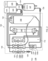
- Figure 2 is a side view of the processing kit 100 and shows the layout of the fluid paths 110 within the support frame 105, and its external connections which in practice are made externally of the housing 12 when the kit 100 is inserted into the housing 12 in use.
- the kit 100 once inserted, is connected to a buffer/wash liquid supply 123, to a source of suspended cells or similar biological material 125, to a waste collection 129 and to a harvesting collection chamber 127, each by means of a respective sterile connector 122, 124, 128 and 126.
- any of the buffer supply 123, source 125, waste collection 129, and harvesting collection chamber 127 can be pre-connected to the fluid paths 110.
- extended respective fluid connection tubing is coiled close to the frame 105 initially, terminating in said buffer supply 123, source 125, waste collection 129, and/or harvesting collection chamber 127, and the extended tubing is uncoiled to be fed outside of the housing 12 once the kit 100 is inserted into the housing.
- the through aperture 120 allows a pumping action to be exerted on fluids within the flexible tubular paths 120a, 120b, 120c and 120d which cross the aperture.
- the through aperture 130 allows the tubular paths 130a and 130b that cross that aperture to be pinched to provide a valve action.
- the processing reservoir 150 acts as fluid holding chamber and is part of the recirculating loop, through which the cell-containing fluid actively recirculates during most of the concentration and washing process performed by the instrument 10. It is important to determine the total volume/mass of fluids in the whole processing loop, which includes the fluid paths110, the filter 140 and the processing reservoir 150. That total will vary in use because, for example, the amount of waste fluid taken away and the amount of buffer added will alter the total volume. However, since all components except the processing reservoir 150 have a fixed working volume, the variable mass in the processing reservoir 150 is all that needs to be measured to determine the total processing loop volume/mass. Thus, the reservoir 150 includes a hanger 152 which allows its weight to be measured and thereby the total fluid volume/mass can be determined.
- Figure 3 shows a part of the frame 105 inserted into the housing 12.
- the frame includes guiding formations for example I the ofrm of pegs , or ribs 112 top and bottom which locate slideably in an open ended groove 23 formed in a top guide rail 22 supported by a rigid device frame 20 within the housing 12, to slideably support and locate the kit 100.
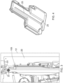
- a bottom guide rail 24 is shown which also includes a groove 25 to accept pegs or a rib (not shown) on the bottom of the frame 105.
- the processing kit 100 is loaded into the housing 12.
- the lower peg or rib and groove are wider than the top for two reasons: a) to make it obvious to the user which end is the top and to prevent incorrect insertion of frame 105, and b) to make it easier to clean the lower rail in the event of a processing kit leak.
- the bottom guide rail 24 has large radii and is dish shaped to catch any leakage.
- An adjustable roller detent feature (not shown) provides user tactile feedback to alert the user to stop pushing the processing kit into the housing.
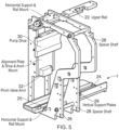
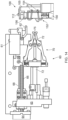
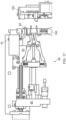
- FIG. 5 shows the device frame 20 in more detail, with the housing 12 removed for clarity.
- the direction of insertion of the kit 100 is shown by arrow, so the device frame 20 is viewed in this illustration from the rear of the housing 12 shown in Figure 1 .
- the device frame 20 comprises two plates 26 held in spaced relation by spacer fixings 28.
- the top and bottom guide rails 22 and 24 run in parallel each mounted to both of the two spaced plates 26.
- a shoe 30 for reacting the forces of a peristaltic pump rotor (described in more detail below) and an anvil to react forces exerted by a pinch valve (described in more detail below).
- the shoe 30 and anvil 32 in use align with the through apertures 120 and 130 respectively.
- Figure 6 shows the device frame 20, and pivotably mounted on the frame via a pivot 42, a pump assembly 40.
- the pump assembly in use, with the processing kit inserted into the housing 12 between guide rails 22 and 24, is pivoted in the direction of arrow R about pump pivot 42, relative to the stationary frame 20, to interact with the flexible tubes 120a,b,c and d as well as the flexible tubes 130a and b, using the shoe 30 and anvil 32 as reaction faces. Additional alignment is effected by guide pins 48 rigidly mounted to the assembly 40.
- the pump assembly 40 interfaces with a processing kit 100 to selectively pump fluid through the fluid paths 110 with, in this instance, a peristaltic action.
- the assembly 40 includes a 3 state pinch valve to direct the flow appropriately by the use of cams which compress and close the cooperating flexible tubes.
- the pump and valve each described in more detail below, are supported on the frame 20 such that operational forces are isolated from the surrounding housing. Disengagement of the pump and valve is effected by pivoting in a direction opposite to arrow R, prior to removal of a used processing kit 100.
- FIG 7 shows the pump assembly in more detail, removed from the frame 20, and viewed in the direction of arrow A in Figure 6 .
- the heads are each formed from sets of rollers each mounted for rotation about a roller pin, and each pin mounted for rotation about a pump axis P, thereby forming the head of a peristaltic pump.
- the four heads share the same pump axis P but can be rotated independently by four different servo type motors 46 acting on drive belts to provide controlled and reversible fluid pressure differentials in the fluid paths 120a to d.
- the pivoting of the whole pump assembly 40 into a pumping position is effected by an electrical actuator 44 mounted to the assembly 40 and reacting against the frame 20.
- guide pins 48 cooperate with complementary formations on the processing kit support frame 105, so that the kit and pump heads are aligned more accurately than relying only on the guide rails 22 and 24.
- the pump heads have six generally evenly spaced rotors, which when engaged against a shoe 30 of approximately 70° arc provides at least one roller always in contact with the shoe, thereby preventing reverse fluid flow and fluid flow if the pump is not turning.
- the pump assembly is shown in yet more detail in Figure 8 , where each of the four pump drive motors 46 are visible along with one of the toothed drive belts 47 and tension screws 49, used to impart tension in the drive belts 47.
- the drive belts' pulleys are sized to provide approximately a 2:1 reduction in speed of the motor at the pump head.
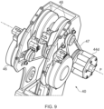
- FIG 9 shows another view of the pump assembly.
- the pump head 44d is shown. It will be observed that this pump head is wider than the other pump heads in the pump axis direction P. This wider pump head 44d allows two or more flexible tubes to be engaged simultaneously, thereby providing increased fluid flow if required. This wider head arrangement allows a processing pump flow rate of up to 3000 mL/min at around 280 rpm motor speed.
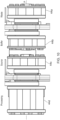
- FIG 10 shows the pumps heads 44a,b,c and d.
- the four heads function to circulate fluid from the processing reservoir 150, to the filter 140, and back to the reservoir or to a collection point 127 (head 44d acting on tube 120d), to bring in cells in suspension from the source 125 (head 44c acting on tube 120c), to bring in buffer/wash solution 123 (head 44b acting on tube 120b) and to remove waste permeate 129 from the filter 130 (head 44a acting on tube 120a).
- head 44d acting on tube 120d the processing reservoir 150, to the filter 140, and back to the reservoir or to a collection point 127 (head 44d acting on tube 120d), to bring in cells in suspension from the source 125 (head 44c acting on tube 120c), to bring in buffer/wash solution 123 (head 44b acting on tube 120b) and to remove waste permeate 129 from the filter 130 (head 44a acting on tube 120a).
- head 44d acting on tube 120d
- wider head 44d may in other arrangements act on more than one
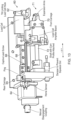
- FIG 11 shows a pinch valve assembly 50 which is mounted underneath the pump motor 464 and pump head 44and pivots into position ready for operation together with the pump assembly 40.
- the pinch valve assembly 50 closes and opens process and collection fluid paths by pinching the tubes 130a and 130b against the anvil surface 32.
- the assembly includes a single linear actuator 55 which includes an electric stepper motor 56, for rotatably driving a lead screw 58 both clockwise and counterclockwise, which in turn moves a carriage 57 linearly back and forth in the direction of arrow C on a rail 53.
- the carriage 57 includes two rollers 54a and 54b, which act on cam profiles 51a and 51b formed on the back of two spring loaded valve arms 53a and 53b.
- the arms 53a and 53b are urged against the respective rollers 54a and 54b.
- the arms have fingers 52a and 52b, the tips of which press against the tubes 130a and 130b aligned in the valve's operative position with the anvil 32.
- the cam profiles 51a and 51b have 'open' portions (58a and 58b) which allow fluid flow and 'closed' portions (59a and 59b) which prevent substantial flow.
- the sequence of open and closed positions for the two fingers is: 130a closed, 130b open (the position shown in Figure 11 ); 130a closed, 130b closed (at the mid-position of carriage 57); and 130a open, 130b closed (at the rightmost position of the carriage 57 when viewed in the same direction of view as illustrated in Figure 11 ). It will be noted that no power is needed to hold the arms in the open or closed positions, because such positions may need to be maintained for long periods of time during possessing. It should also be noted that an open/open position is deliberately not possible to prevent unwanted fluid flows.
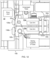
- Figure 12 shows a horizontal cross section through the anvil 32, through the valve arms 53a and 53b and through carriage rollers 54a and 54b, which in this view are in their mid-position, such that both fingers 52a and 52b are acting to compress and thereby close flexible tubes 130a and 130b (shown schematically in this illustration). It will be noted that the starting positions of the tubes is also illustrated.
- the fingers 52a and 52b are initially retracted (along with the pump heads), and are only brought into a position ready to operate by pivoting forward of the pump assembly 40 once the processing kit 100 is in place. Then the fingers operate by opening or closing the tubes according to an operation protocol.
- the valve assembly 50 can be adjusted initially independently of the position of the pump assembly 40, so that the correct pinch load can be obtained.
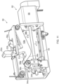
- Figure 13 shows a transfer mechanism 60 housed within the housing 12 for transferring the processing reservoir 150 of the processing kit 100 onto a weighing hook 62 so that the volume of liquids in the reservoir can be estimated in use.
- the mechanism 60 removes the reservoir 150 from the processing kit support frame 105, transfers it to hook 62, which is supported by a load cell 61 where it will stay for the duration of a processing run, and then returns the reservoir 150 to the support frame 105.
- the processing reservoir 150 is mounted on the support frame 105 as supplied to the user and inserted into the housing in that state. It is reattached to the support frame before the user removes the processing kit from the housing. During a run, the process reservoir and connected tubing will hang freely on the load cell hook to enable mass measurement.
- the motion of the mechanism 60 is controlled by one stepper motor 64 and a lead screw 66 which directly controls X direction movement of a rear carriage 65, travelling on a linear rail 68 as the lead screw 66 is rotated by the motor 64.
- the rear carriage 66 supports an extension shaft 73 that moves with the carriage 66.
- the shaft 73 has a distal end 71 which includes a profiled head 72 ( Figure 14 ).
- a front carriage 70 is moveable on the rail 68 also, but is not driven by the lead screw. Rather its movement is controlled by movement of the profiled head 74 and explained in more detail below.
- the mechanism 60 starts in the position shown in Figure 14 , which is a side view in the direction of arrow y in Figure 5 . That position allows for insertion of the processing kit 100 into the housing 12, and brings the hanger 152 of the processing reservoir into an alignment with the mechanism 60.
- the hanger 152 includes two resilient arms 154 which sit in supporting apertures in the processing kit frame 105. In this initial position the hanger arms support the processing reservoir and keep it resiliently in place on the frame 105. On the hanger 152, above the arms is a further aperture 156 which accepts the hook 62.
- the rear carriage 65 is then driven in the positive X-direction as shown in Figure 15 .
- This movement ultimately pushes the profiled head 72 into a latch arrangement which has a pair of sprung expansion arms 75.
- the spring force required to open the expansion arms 75 is such that the expansion arms remain closed and the front carriage 70 is driven forward in the positive X direction also as shown in figure 15 .
- the front carriage 70 is driven forward in this way until it reaches a hard stop formed by the reservoir clip on the support frame, as shown in Figure 16 .
- the frame 105 cannot move because it is being held in place by the upper and lower guides of the guide rails 22 and 24.
- the rear carriage continues to move forward while the front carriage is stopped, causing the profiled head 72 to force apart the expansion arms 75 apart and into latching cooperating engagement with the resilient arms 154 of the hanger 152.
- the expansion arms distort the resilient arms to release their grip on the hanger 152, and the hook 62 enters the aperture 156.
- the rear carriage is driven by the motor 64 and leadscrew 68 in the negative X direction, thereby detaching the hanger 152 from the frame 105, and moving the hanger 152, with the reservoir 150 away from the frame 105.
- the front carriage 70 is dragged backwards until it hits a stop. In this position the hanger 152 drops onto the load cell hook 62.
- the rear carriage 65 continues moving and the profiled head 72 is pulled out from between the expansion arms 75, thus returning them to their neutral position shown. At this point the hanger 152 is no longer held in place by the expansion arms and therefore slides down the load cell hook 62, finally bringing weight to bear on the load cell 61.
- the rear carriage 65 is now back to its initial, home position, and no parts of the mechanism, apart from the hook 61 touch the reservoir 150, or its hanger 152.
- the front carriage 70 reaches a stop when the hanger 152 is flush against the support frame 105, with the support frame 105 held in place by the upper and lower guides 22 and 24.
- the rear carriage 65 continues to drive forward and pushes the expansion arms apart. This step ensures that the hanger 152 is properly located in the Z-dimension and that the resilient arms 154 are met with no resistance passing through their apertures on the frame 105. This action is different from the reservoir retrieval described above; the profiled head 72 is driven past the ends of the expansion arms 75, as shown in Figure 18 .
- the hanger 152 will be securely reattached to the support frame 105 and the expansion arms 75, profiled head 72, and load cell hook 62 can be extracted.
- the rear carriage 65 drives backwards, dragging the front carriage 70 with it.
- the front carriage 70 reaches a stop while the rear carriage 65 continues moving backward. This allows the profiled head to be pulled through the expansion arms 75 once again and reset for a new process kit and new processing reservoir, as shown in Figure 19 .
- the instrument 10 includes mechanical elements including the pump, pinch valve and weighing mechanisms described above, which are reusable, together with a removeable and disposable low cost processing kit 100 which comprises all the fluid elements (e.g. paths 110, filter 140 and fluid processing reservoir 150) necessary for cell harvesting.
- the combination of these features results in a cell harvesting instrument which is easy to use and can be readied for the next harvesting batch quickly. No mechanical parts come into contact with fluids, which means that cleaning of the mechanical parts between harvesting is not required.
- the instrument 10 is particularly suitable for concentrating and/or washing human cells, for example for subsequent use in cellular therapeutic applications where the readily achievable aseptic operating conditions of the instrument provide a much improved chance of therapeutic success, as well as reduced costs and turn-around times.
Landscapes
- Health & Medical Sciences (AREA)
- Life Sciences & Earth Sciences (AREA)
- Engineering & Computer Science (AREA)
- Chemical & Material Sciences (AREA)
- Bioinformatics & Cheminformatics (AREA)
- Organic Chemistry (AREA)
- Wood Science & Technology (AREA)
- Zoology (AREA)
- Biotechnology (AREA)
- General Health & Medical Sciences (AREA)
- Biomedical Technology (AREA)
- Biochemistry (AREA)
- General Engineering & Computer Science (AREA)
- Sustainable Development (AREA)
- Microbiology (AREA)
- Genetics & Genomics (AREA)
- Heart & Thoracic Surgery (AREA)
- Hematology (AREA)
- Animal Behavior & Ethology (AREA)
- Molecular Biology (AREA)
- Veterinary Medicine (AREA)
- Public Health (AREA)
- Anesthesiology (AREA)
- Vascular Medicine (AREA)
- Chemical Kinetics & Catalysis (AREA)
- Clinical Laboratory Science (AREA)
- Analytical Chemistry (AREA)
- Dispersion Chemistry (AREA)
- Medicinal Chemistry (AREA)
- Apparatus Associated With Microorganisms And Enzymes (AREA)
- Sampling And Sample Adjustment (AREA)
Description
- This invention relates to cell harvesting apparatus, to the improved functioning of such apparatus, and to improvements in the components thereof.
- Effective harvesting of cells from various sources is required for different therapeutic applications, such as cell therapy, or tissue engineering. The examples of therapeutic applications include but are not limited to autologous or allogeneic transplantation of stem cells, transplantation of matured functional cells, T cells, modified human cells including T cells, or xenotransplantation of non-human cells. The applications facilitate healing of the damaged tissue or an organ, by regenerating cells to improve the condition of a diseased state.
- For translational research, which facilitates the development and implementation of scientific discoveries to prevent, diagnose, and treat disease using state-of-the-art technologies, a range of potential cell types require isolation prior to modification, activation, and/or expansion. To meet this translational market need, the cells are first required to be concentrated and washed to remove any impurities. For preserved cell applications, where previously separated mononucleated cells (MNC) are stored in cryogenic temperatures after suspension in media containing preservatives such as dimethylsulfoxide (DMSO), the cells need to be washed, typically through a dilution process, several times to minimize the preservative's concentration before re-concentrating and re-suspending the cells for use. Therefore, the processing of cryo-preserved cells is necessary before use in any application, specifically for therapeutic application or research purposes.
- For both of the examples, a suspension of such cells should be processed to concentrate and should be washed extensively to ensure high quality- herein, such concentration optionally including one or more wash cycles is referred to as cell harvesting. Although various methods and systems for harvesting cells are known in the art, the quality and quantity output of these systems are insufficient for therapeutic application. Therefore, systems and methods for harvesting cells under aseptic conditions not necessarily in large scale processing facilities, but with reduced infrastructure requirements and robust operational efficiency, are highly desirable. In additional, equipment which is simple to operate and to maintain is desirable also.
- Methods and devices for harvesting cells are described in patent application
US2013/0029411 , and result in high quality cell samples, which are devoid of significant residual impurities or preservatives. These methods and devices resolve some of the problems associated with the cells used for translational applications or cells recovered from cryogenic preserved cells. - An example of method of harvesting cells from a fluidic material in a processing loop as shown in
US2013/0029411 comprises, a processing chamber and a filtering device wherein the fluidic material has a volume and the processing chamber has an overall capacity, comprises circulating the fluidic material through the processing loop and balancing an influx of the fluidic material into the processing chamber with a permeate flux of the filtering device to maintain the volume of the fluidic material in the processing chamber at a constant value, concentrating the cells by increasing the permeate flux of the filtering device relative to the influx of the fluidic material into the processing chamber; and collecting the concentrated cells in a collection chamber. Other examples of the method of harvesting cells from a fluidic material in a processing loop are shown inUS2013/0029411 . - In addition, embodiments of the cell harvesting devices are shown
US2013/0029411 comprising, for example, a processing loop comprising a processing chamber and a filtering device; a network of input and output lines operatively coupled to one or more of a source chamber, buffer chamber, waste chamber and collection chamber, and a controller that controls a mass of the processing chamber at a desired value based on an influx and a permeate flux of the processing loop.WO 03/087292 - The inventors have devised improvements to the methods and devices disclosed in
US2013/0029411 , which have resulted in improved performance and reliability, as well as reduced costs in the consumable parts of the improvements. Embodiments of the invention address the shortcomings of known cell harvesting equipment. The invention is set out in the independent claims herein, with preferred features defined in dependent claims. - These and other features, aspects, and advantages will become better understood when the following detailed description is read with reference to the accompanying drawings in which like characters represent like parts throughout the drawings, wherein:
-
Figure 1 shows a cell harvesting instrument together with its disposable processing kit; -
Figure 2 shows a schematic representation of the disposable processing kit shown inFigure 1 ; -
Figure 3 shows the processing kit in place in the instrument; -
Figure 4 shows a receiving rail mountable in the housing of the instrument ofFigure 1 for guiding the processing kit into place in the housing; -
Figure 5 shows a processing kit receiving frame which is housed within the housing of the instrument shown inFigure 1 ; -
Figures 6 to 10 show details of a peristaltic pump mountable in the frame shown inFigure 5 -
Figures 11 and12 show details of a pinch valve again mountable to the frame shown inFigure 5 ; -
Figure 13 shows a pictorial view of a processing reservoir transfer mechanism; and -
Figures 14 to 19 show side views of the transfer mechanism ofFigure 13 , in different functional positions. - To more clearly and concisely describe and point out the subject matter of the claimed invention, the following definitions are provided for specific terms, which are used in the following description and the appended claims. Throughout the specification, use of specific terms should be considered as non-limiting examples.
- Referring to
Figure 1 there is shown acell harvesting instrument 10, which in use functions to take in liquids which include suspended cells or similar microbiological material, for the purpose of largely separating the cells from the liquid or reducing the liquid content of the suspension. The instrument can function to wash the cells etc. one or more times to rid the separated cells of unwanted material. A preferred functioning regime can be found inUS2013/0029411 . - The
instrument 10 comprises ahousing 12 which has atouch screen 14 and adoor 16, shown closed and, in chain dotted lines, shown in an open position 16'. Thedoor 16 allows the insertion and removal of adisposable processing kit 100. Thekit 100 is generally flat with aperipheral support frame 105 of thickness x' in the x direction of around 30- 40mm. In other words,fluid paths 110 within the frame, and additional components of the kit described below, lie substantially in a generally flat, single, plane. Theliquid paths 110, shown in chain dotted lines have, in this case, four inlets/outlets fluid paths 110 are mostly constructed from medical grade tubing, for example PVC tubing. Other than those inlets/outlets 122-128, thefluid paths 110 are functional closed circuits, which are sealed, other than at vents which have filters containing sub-micron pore size filters to allow gases to escape, but to prevent ingress of contamination.. In particular, mechanical parts contained within thehousing 12, do not contact any fluids in the paths, thereby maintaining sterility of the paths in use. Theframe 105 also includes through-apertures frame 105 to the other, providing regions where the tubes of the fluid paths which pass across the apertures can be manipulated from both sides of the frame by said mechanical parts. Where the fluid paths cross the apertures, these tubes need to be flexible, and so these tubes are preferably formed from silicon tubing. - The
kit 100 further includes atangential flow filter 140, and adetachable process reservoir 150, in this case in the form of a moulded plastics container. Theprocessing kit 100 is inserted into and removed from thehousing 12 in the direction of arrow y. -
Figure 2 is a side view of theprocessing kit 100 and shows the layout of thefluid paths 110 within thesupport frame 105, and its external connections which in practice are made externally of thehousing 12 when thekit 100 is inserted into thehousing 12 in use. Thekit 100 once inserted, is connected to a buffer/washliquid supply 123, to a source of suspended cells or similarbiological material 125, to awaste collection 129 and to aharvesting collection chamber 127, each by means of a respectivesterile connector buffer supply 123,source 125,waste collection 129, andharvesting collection chamber 127 can be pre-connected to thefluid paths 110. In practice, extended respective fluid connection tubing is coiled close to theframe 105 initially, terminating in saidbuffer supply 123,source 125,waste collection 129, and/orharvesting collection chamber 127, and the extended tubing is uncoiled to be fed outside of thehousing 12 once thekit 100 is inserted into the housing. The throughaperture 120 allows a pumping action to be exerted on fluids within the flexibletubular paths through aperture 130 allows thetubular paths processing reservoir 150 acts as fluid holding chamber and is part of the recirculating loop, through which the cell-containing fluid actively recirculates during most of the concentration and washing process performed by theinstrument 10. It is important to determine the total volume/mass of fluids in the whole processing loop, which includes the fluid paths110, thefilter 140 and theprocessing reservoir 150. That total will vary in use because, for example, the amount of waste fluid taken away and the amount of buffer added will alter the total volume. However, since all components except theprocessing reservoir 150 have a fixed working volume, the variable mass in theprocessing reservoir 150 is all that needs to be measured to determine the total processing loop volume/mass. Thus, thereservoir 150 includes ahanger 152 which allows its weight to be measured and thereby the total fluid volume/mass can be determined. -
Figure 3 shows a part of theframe 105 inserted into thehousing 12. In this instance the frame includes guiding formations for example I the ofrm of pegs , orribs 112 top and bottom which locate slideably in an open endedgroove 23 formed in atop guide rail 22 supported by arigid device frame 20 within thehousing 12, to slideably support and locate thekit 100. - In
Figure 4 abottom guide rail 24 is shown which also includes agroove 25 to accept pegs or a rib (not shown) on the bottom of theframe 105. Theprocessing kit 100 is loaded into thehousing 12. Thebottom guide rail 24 and a top rail (22Figure 5 ), both have grooves that interface with respective pegs or ribs on the processing kit. The lower peg or rib and groove are wider than the top for two reasons: a) to make it obvious to the user which end is the top and to prevent incorrect insertion offrame 105, and b) to make it easier to clean the lower rail in the event of a processing kit leak. To aid cleanup, thebottom guide rail 24 has large radii and is dish shaped to catch any leakage. An adjustable roller detent feature (not shown) provides user tactile feedback to alert the user to stop pushing the processing kit into the housing. -
Figure 5 shows thedevice frame 20 in more detail, with thehousing 12 removed for clarity. The direction of insertion of thekit 100 is shown by arrow, so thedevice frame 20 is viewed in this illustration from the rear of thehousing 12 shown inFigure 1 . Thedevice frame 20 comprises twoplates 26 held in spaced relation byspacer fixings 28. The top andbottom guide rails plates 26. Also mounted to the plates are ashoe 30 for reacting the forces of a peristaltic pump rotor (described in more detail below) and an anvil to react forces exerted by a pinch valve (described in more detail below). Theshoe 30 andanvil 32, in use align with the throughapertures -
Figure 6 shows thedevice frame 20, and pivotably mounted on the frame via apivot 42, apump assembly 40. The pump assembly in use, with the processing kit inserted into thehousing 12 betweenguide rails pump pivot 42, relative to thestationary frame 20, to interact with theflexible tubes 120a,b,c and d as well as theflexible tubes 130a and b, using theshoe 30 andanvil 32 as reaction faces. Additional alignment is effected byguide pins 48 rigidly mounted to theassembly 40. Thepump assembly 40 interfaces with aprocessing kit 100 to selectively pump fluid through thefluid paths 110 with, in this instance, a peristaltic action. Theassembly 40 includes a 3 state pinch valve to direct the flow appropriately by the use of cams which compress and close the cooperating flexible tubes. The pump and valve, each described in more detail below, are supported on theframe 20 such that operational forces are isolated from the surrounding housing. Disengagement of the pump and valve is effected by pivoting in a direction opposite to arrow R, prior to removal of a usedprocessing kit 100. -
Figure 7 shows the pump assembly in more detail, removed from theframe 20, and viewed in the direction of arrow A inFigure 6 . In this view, fourpump heads flexible tubes 120a,b,c and d respectively. The heads are each formed from sets of rollers each mounted for rotation about a roller pin, and each pin mounted for rotation about a pump axis P, thereby forming the head of a peristaltic pump. The four heads share the same pump axis P but can be rotated independently by four differentservo type motors 46 acting on drive belts to provide controlled and reversible fluid pressure differentials in thefluid paths 120a to d. The pivoting of thewhole pump assembly 40 into a pumping position is effected by anelectrical actuator 44 mounted to theassembly 40 and reacting against theframe 20. During the movement of the pump assembly into an operative position, guide pins 48 cooperate with complementary formations on the processingkit support frame 105, so that the kit and pump heads are aligned more accurately than relying only on the guide rails 22 and 24. The pump heads have six generally evenly spaced rotors, which when engaged against ashoe 30 of approximately 70° arc provides at least one roller always in contact with the shoe, thereby preventing reverse fluid flow and fluid flow if the pump is not turning. - The pump assembly is shown in yet more detail in
Figure 8 , where each of the fourpump drive motors 46 are visible along with one of thetoothed drive belts 47 and tension screws 49, used to impart tension in thedrive belts 47. The drive belts' pulleys are sized to provide approximately a 2:1 reduction in speed of the motor at the pump head. -
Figure 9 shows another view of the pump assembly. In this view thepump head 44d is shown. It will be observed that this pump head is wider than the other pump heads in the pump axis direction P. Thiswider pump head 44d allows two or more flexible tubes to be engaged simultaneously, thereby providing increased fluid flow if required. This wider head arrangement allows a processing pump flow rate of up to 3000 mL/min at around 280 rpm motor speed. -
Figure 10 shows the pumps heads 44a,b,c and d. As labelled, it can be seen that the four heads function to circulate fluid from theprocessing reservoir 150, to thefilter 140, and back to the reservoir or to a collection point 127 (head 44d acting ontube 120d), to bring in cells in suspension from the source 125 (head 44c acting ontube 120c), to bring in buffer/wash solution 123 (head 44b acting ontube 120b) and to remove waste permeate 129 from the filter 130 (head 44a acting ontube 120a). As mentioned above, from speedier processing more than onetube 120 may be provide for each pump head, thuswider head 44d may in other arrangements act on more than onetube 120. -
Figure 11 shows apinch valve assembly 50 which is mounted underneath the pump motor 464 and pump head 44and pivots into position ready for operation together with thepump assembly 40. Thepinch valve assembly 50 closes and opens process and collection fluid paths by pinching thetubes anvil surface 32. The assembly includes a singlelinear actuator 55 which includes anelectric stepper motor 56, for rotatably driving a lead screw 58 both clockwise and counterclockwise, which in turn moves acarriage 57 linearly back and forth in the direction of arrow C on arail 53. Thecarriage 57 includes tworollers cam profiles valve arms arms respective rollers fingers tubes anvil 32. The cam profiles 51a and 51b have 'open' portions (58a and 58b) which allow fluid flow and 'closed' portions (59a and 59b) which prevent substantial flow. Since the fingers are arranged in opposite orientations, the sequence of open and closed positions for the two fingers is: 130a closed, 130b open (the position shown inFigure 11 ); 130a closed, 130b closed (at the mid-position of carriage 57); and 130a open, 130b closed (at the rightmost position of thecarriage 57 when viewed in the same direction of view as illustrated inFigure 11 ). It will be noted that no power is needed to hold the arms in the open or closed positions, because such positions may need to be maintained for long periods of time during possessing. It should also be noted that an open/open position is deliberately not possible to prevent unwanted fluid flows. -
Figure 12 shows a horizontal cross section through theanvil 32, through thevalve arms carriage rollers fingers flexible tubes processing kit frame 105 can be accommodated, thefingers pump assembly 40 once theprocessing kit 100 is in place. Then the fingers operate by opening or closing the tubes according to an operation protocol. Thevalve assembly 50 can be adjusted initially independently of the position of thepump assembly 40, so that the correct pinch load can be obtained. -
Figure 13 shows atransfer mechanism 60 housed within thehousing 12 for transferring theprocessing reservoir 150 of theprocessing kit 100 onto a weighinghook 62 so that the volume of liquids in the reservoir can be estimated in use. In practice themechanism 60 removes thereservoir 150 from the processingkit support frame 105, transfers it to hook 62, which is supported by aload cell 61 where it will stay for the duration of a processing run, and then returns thereservoir 150 to thesupport frame 105. Theprocessing reservoir 150 is mounted on thesupport frame 105 as supplied to the user and inserted into the housing in that state. It is reattached to the support frame before the user removes the processing kit from the housing. During a run, the process reservoir and connected tubing will hang freely on the load cell hook to enable mass measurement. - The motion of the
mechanism 60 is controlled by onestepper motor 64 and alead screw 66 which directly controls X direction movement of arear carriage 65, travelling on alinear rail 68 as thelead screw 66 is rotated by themotor 64. Therear carriage 66 supports an extension shaft 73 that moves with thecarriage 66. The shaft 73 has adistal end 71 which includes a profiled head 72 (Figure 14 ). Afront carriage 70 is moveable on therail 68 also, but is not driven by the lead screw. Rather its movement is controlled by movement of the profiled head 74 and explained in more detail below. - The
mechanism 60 starts in the position shown inFigure 14 , which is a side view in the direction of arrow y inFigure 5 . That position allows for insertion of theprocessing kit 100 into thehousing 12, and brings thehanger 152 of the processing reservoir into an alignment with themechanism 60. Thehanger 152 includes tworesilient arms 154 which sit in supporting apertures in theprocessing kit frame 105. In this initial position the hanger arms support the processing reservoir and keep it resiliently in place on theframe 105. On thehanger 152, above the arms is afurther aperture 156 which accepts thehook 62. - The
rear carriage 65 is then driven in the positive X-direction as shown inFigure 15 . This movement ultimately pushes the profiledhead 72 into a latch arrangement which has a pair of sprungexpansion arms 75. The spring force required to open theexpansion arms 75 is such that the expansion arms remain closed and thefront carriage 70 is driven forward in the positive X direction also as shown infigure 15 . Thefront carriage 70 is driven forward in this way until it reaches a hard stop formed by the reservoir clip on the support frame, as shown inFigure 16 . Theframe 105 cannot move because it is being held in place by the upper and lower guides of the guide rails 22 and 24. Thus, the rear carriage continues to move forward while the front carriage is stopped, causing the profiledhead 72 to force apart theexpansion arms 75 apart and into latching cooperating engagement with theresilient arms 154 of thehanger 152. In this position the expansion arms distort the resilient arms to release their grip on thehanger 152, and thehook 62 enters theaperture 156. - Next, as shown in
Figure 17 , the rear carriage is driven by themotor 64 andleadscrew 68 in the negative X direction, thereby detaching thehanger 152 from theframe 105, and moving thehanger 152, with thereservoir 150 away from theframe 105. - The
front carriage 70 is dragged backwards until it hits a stop. In this position thehanger 152 drops onto theload cell hook 62. Therear carriage 65 continues moving and the profiledhead 72 is pulled out from between theexpansion arms 75, thus returning them to their neutral position shown. At this point thehanger 152 is no longer held in place by the expansion arms and therefore slides down theload cell hook 62, finally bringing weight to bear on theload cell 61. Therear carriage 65 is now back to its initial, home position, and no parts of the mechanism, apart from thehook 61 touch thereservoir 150, or itshanger 152. - Returning the
reservoir 150 to theframe 105 is carried out by reversing the steps described above. Thefront carriage 70 reaches a stop when thehanger 152 is flush against thesupport frame 105, with thesupport frame 105 held in place by the upper andlower guides rear carriage 65 continues to drive forward and pushes the expansion arms apart. This step ensures that thehanger 152 is properly located in the Z-dimension and that theresilient arms 154 are met with no resistance passing through their apertures on theframe 105. This action is different from the reservoir retrieval described above; the profiledhead 72 is driven past the ends of theexpansion arms 75, as shown inFigure 18 . - In this position, the
hanger 152 will be securely reattached to thesupport frame 105 and theexpansion arms 75, profiledhead 72, and loadcell hook 62 can be extracted. Therear carriage 65 drives backwards, dragging thefront carriage 70 with it. Thefront carriage 70 reaches a stop while therear carriage 65 continues moving backward. This allows the profiled head to be pulled through theexpansion arms 75 once again and reset for a new process kit and new processing reservoir, as shown inFigure 19 . - In operation, the
instrument 10 includes mechanical elements including the pump, pinch valve and weighing mechanisms described above, which are reusable, together with a removeable and disposable lowcost processing kit 100 which comprises all the fluid elements (e.g. paths 110,filter 140 and fluid processing reservoir 150) necessary for cell harvesting. The combination of these features results in a cell harvesting instrument which is easy to use and can be readied for the next harvesting batch quickly. No mechanical parts come into contact with fluids, which means that cleaning of the mechanical parts between harvesting is not required. Theinstrument 10 is particularly suitable for concentrating and/or washing human cells, for example for subsequent use in cellular therapeutic applications where the readily achievable aseptic operating conditions of the instrument provide a much improved chance of therapeutic success, as well as reduced costs and turn-around times.
Claims (6)
- A cell harvesting processing kit for separating cells from fluids, and/or for washing cells, the kit comprising sealed fluid paths at least a portion of which are formed from flexible tubing suitable for being externally manipulated by mechanical elements, the kit comprising also a fluid processing reservoir and a filter suitable for retaining cells whilst permeating fluids in said paths, the kit being characterized in that the fluid paths are supported by a generally flat supporting frame such that said paths, reservoir and filter are arranged in a generally flat plane, wherein said fluid processing reservoir is in the form of a container which lies generally flat in the frame and is demountable from the frame and re-attachable to the frame in use,
the kit being characterized in that said supporting frame includes through-apertures, and said flexible tubing is arranged to extend across said apertures such that the tubing is accessible from both sides of the flat supporting frame to allow said external manipulation from both sides of the frame. - A cell harvesting processing kit as claimed in claim 1, wherein said fluid paths include at least one inlet located at the ends of extended flexible tubing for further fluid connection remote from the frame.
- A cell harvesting processing kit as claimed in claim 2, wherein the plural fluid paths and extended fluid paths form a closed fluid processing system arranged such that fluids in the paths do not contact mechanical elements which effect fluid control, for example a fluid pump or pumps and/or a fluid valve or valves.
- A cell harvesting processing kit as claimed in claim 2, wherein said fluid paths further include at least one outlet.
- A method for separating and/or washing cells comprising use of a cell harvesting processing kit as claimed in claim 1 for separating and/or washing cells.
- The method of claim 5, wherein the cells are human cells.
Applications Claiming Priority (2)
| Application Number | Priority Date | Filing Date | Title |
|---|---|---|---|
| US201562270917P | 2015-12-22 | 2015-12-22 | |
| PCT/EP2016/082382 WO2017109072A1 (en) | 2015-12-22 | 2016-12-22 | Improvements in and relating to cell harvesting apparatus |
Publications (2)
| Publication Number | Publication Date |
|---|---|
| EP3394240A1 EP3394240A1 (en) | 2018-10-31 |
| EP3394240B1 true EP3394240B1 (en) | 2025-01-08 |
Family
ID=57794254
Family Applications (1)
| Application Number | Title | Priority Date | Filing Date |
|---|---|---|---|
| EP16825753.3A Active EP3394240B1 (en) | 2015-12-22 | 2016-12-22 | Improvements in and relating to cell harvesting apparatus |
Country Status (4)
| Country | Link |
|---|---|
| US (2) | US11649423B2 (en) |
| EP (1) | EP3394240B1 (en) |
| CN (2) | CN121674196A (en) |
| WO (1) | WO2017109072A1 (en) |
Families Citing this family (6)
| Publication number | Priority date | Publication date | Assignee | Title |
|---|---|---|---|---|
| US11291931B2 (en) | 2014-12-15 | 2022-04-05 | Akadeum Life Sciences, Inc. | Method and system for buoyant separation |
| US11649423B2 (en) | 2015-12-22 | 2023-05-16 | Global Life Sciences Solutions Usa Llc | Cell harvesting apparatus |
| JP7189314B2 (en) | 2018-07-09 | 2022-12-13 | アカデューム ライフ サイエンセズ,インコーポレイテッド | Systems and methods for handling airborne particles |
| US11819842B2 (en) | 2021-08-26 | 2023-11-21 | Akadeum Life Sciences, Inc. | Method and system for buoyant separation |
| US12196754B2 (en) | 2022-04-01 | 2025-01-14 | Akadeum Life Sciences, Inc. | Method and system for buoyant-particle-assisted cell therapy |
| JP2026511329A (en) | 2023-02-14 | 2026-04-14 | アカデューム ライフ サイエンセズ,インコーポレイテッド | Partially or fully automated buoyancy-assisted separation method and system |
Family Cites Families (23)
| Publication number | Priority date | Publication date | Assignee | Title |
|---|---|---|---|---|
| DE2908169A1 (en) | 1979-03-02 | 1980-09-11 | Hartmann & Braun Ag | ANALYZER FOR GASES OR LIQUIDS |
| US4806247A (en) | 1985-04-12 | 1989-02-21 | Baxter International Inc. | Plasmapheresis system and method |
| DE3720733A1 (en) | 1987-03-31 | 1988-10-13 | Lufthansa Service Gmbh | METHOD FOR THE MICROBIOLOGICAL EXAMINATION OF SAMPLES |
| US4851126A (en) | 1987-11-25 | 1989-07-25 | Baxter International Inc. | Apparatus and methods for generating platelet concentrate |
| US6722395B2 (en) | 1998-01-13 | 2004-04-20 | James W. Overbeck | Depositing fluid specimens on substrates, resulting ordered arrays, techniques for analysis of deposited arrays |
| US20020068358A1 (en) * | 1998-04-28 | 2002-06-06 | Campbell Michael J. | In vitro embryo culture device |
| US8492140B2 (en) * | 2002-04-08 | 2013-07-23 | Octane Biotech Inc. | Automated tissue engineering system |
| US7919307B2 (en) * | 2005-05-09 | 2011-04-05 | Alpha Plan Gmbh | Supply system for cell culture module |
| US8177974B2 (en) | 2006-04-14 | 2012-05-15 | Emd Millipore Corporation | Disposable tangential flow filtration device holder |
| ES2785963T3 (en) | 2009-07-24 | 2020-10-08 | Emd Millipore Corp | Feeding bag construction |
| US9034280B2 (en) | 2009-12-16 | 2015-05-19 | General Electric Corporation | High-throughput methods and systems for processing biological materials |
| CN103153359B (en) | 2009-12-24 | 2015-12-02 | 昆山韦睿医疗科技有限公司 | Automatic peritoneal dialysis circulation system and its application |
| JP2012152124A (en) | 2011-01-25 | 2012-08-16 | Nikon Corp | Culture observation apparatus |
| CN103415329B (en) | 2011-03-11 | 2015-05-13 | 汾沃有限公司 | Membrane separation device, system and method using same, and data management system and method |
| WO2013012822A1 (en) * | 2011-07-15 | 2013-01-24 | Cardinal Health 414, Llc | Systems, methods, and devices for producing, manufacturing, and control of radiopharmaceuticals |
| US10934519B2 (en) | 2011-07-29 | 2021-03-02 | Global Life Sciences Solutions Usa Llc | Systems, methods and control laws for cell harvesting |
| EP2720730B1 (en) | 2011-09-22 | 2017-01-11 | Fenwal, Inc. | Disposable fluid circuits and methods for cell washing |
| MX353212B (en) * | 2011-12-07 | 2018-01-08 | Cytovera Inc | Method and device for sample processing. |
| EP2883667B1 (en) | 2013-12-10 | 2020-01-15 | F.Hoffmann-La Roche Ag | Device and method for gripping vessels |
| US10077421B2 (en) | 2014-04-24 | 2018-09-18 | Terumo Bct, Inc. | Measuring flow rate |
| US11649423B2 (en) | 2015-12-22 | 2023-05-16 | Global Life Sciences Solutions Usa Llc | Cell harvesting apparatus |
| US10982183B2 (en) | 2015-12-22 | 2021-04-20 | Global Life Sciences Solutions Usa Llc | Cell harvesting apparatus |
| WO2017109074A1 (en) | 2015-12-22 | 2017-06-29 | Ge Healthcare Bio-Sciences Corp. | Improvements in and relating to cell harvesting apparatus |
-
2016
- 2016-12-22 US US16/065,413 patent/US11649423B2/en active Active
- 2016-12-22 CN CN202511908413.4A patent/CN121674196A/en active Pending
- 2016-12-22 EP EP16825753.3A patent/EP3394240B1/en active Active
- 2016-12-22 WO PCT/EP2016/082382 patent/WO2017109072A1/en not_active Ceased
- 2016-12-22 CN CN201680082332.6A patent/CN108699503A/en active Pending
-
2023
- 2023-04-06 US US18/296,554 patent/US12428612B2/en active Active
Also Published As
| Publication number | Publication date |
|---|---|
| EP3394240A1 (en) | 2018-10-31 |
| US20190017005A1 (en) | 2019-01-17 |
| US12428612B2 (en) | 2025-09-30 |
| CN108699503A (en) | 2018-10-23 |
| US20230242852A1 (en) | 2023-08-03 |
| US11649423B2 (en) | 2023-05-16 |
| CN121674196A (en) | 2026-03-17 |
| WO2017109072A1 (en) | 2017-06-29 |
Similar Documents
| Publication | Publication Date | Title |
|---|---|---|
| US12428612B2 (en) | Cell harvesting apparatus | |
| US20240368515A1 (en) | Cell harvesting apparatus | |
| US12110482B2 (en) | Instruments for processing cells | |
| US10982183B2 (en) | Cell harvesting apparatus | |
| US11807841B2 (en) | Cell harvesting apparatus | |
| JP6240601B2 (en) | Cell collection system, method and control law | |
| JP2011509657A (en) | Apparatus and method for separating biological material by filtration | |
| JP7143414B2 (en) | sampling device | |
| CN116547078A (en) | Culture Vessels for Bioprocessing Systems | |
| CA3202594A1 (en) | Systems and methods for cell enrichment, isolation and formulation | |
| CA3202075A1 (en) | Bioprocessing system and methods | |
| JP2025529164A (en) | Fluid transfer systems, devices, and methods for bioprocessing | |
| CN114432954A (en) | Even equipment of shaking is used in detection of hematology branch of academic or vocational study vein blood sample | |
| CN114602321B (en) | A Magazine Filter Replacement System for Environmental DNA Sampling | |
| CN114577524A (en) | Cartridge magazine type filter membrane replacing device and system based on automatic return for environmental DNA sampling | |
| CN113557043B (en) | Cell washing device | |
| CN120960543A (en) | A dual-centrifugation plasma purification system | |
| CA3201296A1 (en) | System and method for heat and mass transfer for a bioprocessing system | |
| JP2005273656A (en) | Feed pump |
Legal Events
| Date | Code | Title | Description |
|---|---|---|---|
| STAA | Information on the status of an ep patent application or granted ep patent |
Free format text: STATUS: UNKNOWN |
|
| STAA | Information on the status of an ep patent application or granted ep patent |
Free format text: STATUS: THE INTERNATIONAL PUBLICATION HAS BEEN MADE |
|
| PUAI | Public reference made under article 153(3) epc to a published international application that has entered the european phase |
Free format text: ORIGINAL CODE: 0009012 |
|
| STAA | Information on the status of an ep patent application or granted ep patent |
Free format text: STATUS: REQUEST FOR EXAMINATION WAS MADE |
|
| 17P | Request for examination filed |
Effective date: 20180723 |
|
| AK | Designated contracting states |
Kind code of ref document: A1 Designated state(s): AL AT BE BG CH CY CZ DE DK EE ES FI FR GB GR HR HU IE IS IT LI LT LU LV MC MK MT NL NO PL PT RO RS SE SI SK SM TR |
|
| AX | Request for extension of the european patent |
Extension state: BA ME |
|
| DAV | Request for validation of the european patent (deleted) | ||
| DAX | Request for extension of the european patent (deleted) | ||
| RAP1 | Party data changed (applicant data changed or rights of an application transferred) |
Owner name: GLOBAL LIFE SCIENCES SOLUTIONS USA LLC |
|
| P01 | Opt-out of the competence of the unified patent court (upc) registered |
Effective date: 20230526 |
|
| GRAP | Despatch of communication of intention to grant a patent |
Free format text: ORIGINAL CODE: EPIDOSNIGR1 |
|
| STAA | Information on the status of an ep patent application or granted ep patent |
Free format text: STATUS: GRANT OF PATENT IS INTENDED |
|
| INTG | Intention to grant announced |
Effective date: 20240916 |
|
| GRAS | Grant fee paid |
Free format text: ORIGINAL CODE: EPIDOSNIGR3 |
|
| GRAA | (expected) grant |
Free format text: ORIGINAL CODE: 0009210 |
|
| STAA | Information on the status of an ep patent application or granted ep patent |
Free format text: STATUS: THE PATENT HAS BEEN GRANTED |
|
| AK | Designated contracting states |
Kind code of ref document: B1 Designated state(s): AL AT BE BG CH CY CZ DE DK EE ES FI FR GB GR HR HU IE IS IT LI LT LU LV MC MK MT NL NO PL PT RO RS SE SI SK SM TR |
|
| REG | Reference to a national code |
Ref country code: GB Ref legal event code: FG4D |
|
| REG | Reference to a national code |
Ref country code: CH Ref legal event code: EP |
|
| REG | Reference to a national code |
Ref country code: DE Ref legal event code: R096 Ref document number: 602016090910 Country of ref document: DE |
|
| REG | Reference to a national code |
Ref country code: IE Ref legal event code: FG4D |
|
| REG | Reference to a national code |
Ref country code: LT Ref legal event code: MG9D |
|
| REG | Reference to a national code |
Ref country code: NL Ref legal event code: MP Effective date: 20250108 |
|
| REG | Reference to a national code |
Ref country code: AT Ref legal event code: MK05 Ref document number: 1758350 Country of ref document: AT Kind code of ref document: T Effective date: 20250108 |
|
| PG25 | Lapsed in a contracting state [announced via postgrant information from national office to epo] |
Ref country code: NL Free format text: LAPSE BECAUSE OF FAILURE TO SUBMIT A TRANSLATION OF THE DESCRIPTION OR TO PAY THE FEE WITHIN THE PRESCRIBED TIME-LIMIT Effective date: 20250108 |
|
| PG25 | Lapsed in a contracting state [announced via postgrant information from national office to epo] |
Ref country code: RS Free format text: LAPSE BECAUSE OF FAILURE TO SUBMIT A TRANSLATION OF THE DESCRIPTION OR TO PAY THE FEE WITHIN THE PRESCRIBED TIME-LIMIT Effective date: 20250408 |
|
| PG25 | Lapsed in a contracting state [announced via postgrant information from national office to epo] |
Ref country code: FI Free format text: LAPSE BECAUSE OF FAILURE TO SUBMIT A TRANSLATION OF THE DESCRIPTION OR TO PAY THE FEE WITHIN THE PRESCRIBED TIME-LIMIT Effective date: 20250108 |
|
| PG25 | Lapsed in a contracting state [announced via postgrant information from national office to epo] |
Ref country code: PL Free format text: LAPSE BECAUSE OF FAILURE TO SUBMIT A TRANSLATION OF THE DESCRIPTION OR TO PAY THE FEE WITHIN THE PRESCRIBED TIME-LIMIT Effective date: 20250108 |
|
| PG25 | Lapsed in a contracting state [announced via postgrant information from national office to epo] |
Ref country code: ES Free format text: LAPSE BECAUSE OF FAILURE TO SUBMIT A TRANSLATION OF THE DESCRIPTION OR TO PAY THE FEE WITHIN THE PRESCRIBED TIME-LIMIT Effective date: 20250108 |
|
| PG25 | Lapsed in a contracting state [announced via postgrant information from national office to epo] |
Ref country code: NO Free format text: LAPSE BECAUSE OF FAILURE TO SUBMIT A TRANSLATION OF THE DESCRIPTION OR TO PAY THE FEE WITHIN THE PRESCRIBED TIME-LIMIT Effective date: 20250408 Ref country code: IS Free format text: LAPSE BECAUSE OF FAILURE TO SUBMIT A TRANSLATION OF THE DESCRIPTION OR TO PAY THE FEE WITHIN THE PRESCRIBED TIME-LIMIT Effective date: 20250508 |
|
| PG25 | Lapsed in a contracting state [announced via postgrant information from national office to epo] |
Ref country code: HR Free format text: LAPSE BECAUSE OF FAILURE TO SUBMIT A TRANSLATION OF THE DESCRIPTION OR TO PAY THE FEE WITHIN THE PRESCRIBED TIME-LIMIT Effective date: 20250108 |
|
| PG25 | Lapsed in a contracting state [announced via postgrant information from national office to epo] |
Ref country code: LV Free format text: LAPSE BECAUSE OF FAILURE TO SUBMIT A TRANSLATION OF THE DESCRIPTION OR TO PAY THE FEE WITHIN THE PRESCRIBED TIME-LIMIT Effective date: 20250108 Ref country code: PT Free format text: LAPSE BECAUSE OF FAILURE TO SUBMIT A TRANSLATION OF THE DESCRIPTION OR TO PAY THE FEE WITHIN THE PRESCRIBED TIME-LIMIT Effective date: 20250508 |
|
| PG25 | Lapsed in a contracting state [announced via postgrant information from national office to epo] |
Ref country code: BG Free format text: LAPSE BECAUSE OF FAILURE TO SUBMIT A TRANSLATION OF THE DESCRIPTION OR TO PAY THE FEE WITHIN THE PRESCRIBED TIME-LIMIT Effective date: 20250108 Ref country code: GR Free format text: LAPSE BECAUSE OF FAILURE TO SUBMIT A TRANSLATION OF THE DESCRIPTION OR TO PAY THE FEE WITHIN THE PRESCRIBED TIME-LIMIT Effective date: 20250409 |
|
| PG25 | Lapsed in a contracting state [announced via postgrant information from national office to epo] |
Ref country code: AT Free format text: LAPSE BECAUSE OF FAILURE TO SUBMIT A TRANSLATION OF THE DESCRIPTION OR TO PAY THE FEE WITHIN THE PRESCRIBED TIME-LIMIT Effective date: 20250108 |
|
| PG25 | Lapsed in a contracting state [announced via postgrant information from national office to epo] |
Ref country code: SE Free format text: LAPSE BECAUSE OF FAILURE TO SUBMIT A TRANSLATION OF THE DESCRIPTION OR TO PAY THE FEE WITHIN THE PRESCRIBED TIME-LIMIT Effective date: 20250108 |
|
| PG25 | Lapsed in a contracting state [announced via postgrant information from national office to epo] |
Ref country code: SM Free format text: LAPSE BECAUSE OF FAILURE TO SUBMIT A TRANSLATION OF THE DESCRIPTION OR TO PAY THE FEE WITHIN THE PRESCRIBED TIME-LIMIT Effective date: 20250108 |
|
| REG | Reference to a national code |
Ref country code: DE Ref legal event code: R097 Ref document number: 602016090910 Country of ref document: DE |
|
| PG25 | Lapsed in a contracting state [announced via postgrant information from national office to epo] |
Ref country code: DK Free format text: LAPSE BECAUSE OF FAILURE TO SUBMIT A TRANSLATION OF THE DESCRIPTION OR TO PAY THE FEE WITHIN THE PRESCRIBED TIME-LIMIT Effective date: 20250108 |
|
| PG25 | Lapsed in a contracting state [announced via postgrant information from national office to epo] |
Ref country code: EE Free format text: LAPSE BECAUSE OF FAILURE TO SUBMIT A TRANSLATION OF THE DESCRIPTION OR TO PAY THE FEE WITHIN THE PRESCRIBED TIME-LIMIT Effective date: 20250108 Ref country code: CZ Free format text: LAPSE BECAUSE OF FAILURE TO SUBMIT A TRANSLATION OF THE DESCRIPTION OR TO PAY THE FEE WITHIN THE PRESCRIBED TIME-LIMIT Effective date: 20250108 |
|
| PG25 | Lapsed in a contracting state [announced via postgrant information from national office to epo] |
Ref country code: RO Free format text: LAPSE BECAUSE OF FAILURE TO SUBMIT A TRANSLATION OF THE DESCRIPTION OR TO PAY THE FEE WITHIN THE PRESCRIBED TIME-LIMIT Effective date: 20250108 |
|
| PG25 | Lapsed in a contracting state [announced via postgrant information from national office to epo] |
Ref country code: SK Free format text: LAPSE BECAUSE OF FAILURE TO SUBMIT A TRANSLATION OF THE DESCRIPTION OR TO PAY THE FEE WITHIN THE PRESCRIBED TIME-LIMIT Effective date: 20250108 |
|
| PLBE | No opposition filed within time limit |
Free format text: ORIGINAL CODE: 0009261 |
|
| STAA | Information on the status of an ep patent application or granted ep patent |
Free format text: STATUS: NO OPPOSITION FILED WITHIN TIME LIMIT |
|
| 26N | No opposition filed |
Effective date: 20251009 |
|
| PGFP | Annual fee paid to national office [announced via postgrant information from national office to epo] |
Ref country code: GB Payment date: 20251223 Year of fee payment: 10 |
|
| PGFP | Annual fee paid to national office [announced via postgrant information from national office to epo] |
Ref country code: FR Payment date: 20251230 Year of fee payment: 10 |
|
| PG25 | Lapsed in a contracting state [announced via postgrant information from national office to epo] |
Ref country code: IT Free format text: LAPSE BECAUSE OF FAILURE TO SUBMIT A TRANSLATION OF THE DESCRIPTION OR TO PAY THE FEE WITHIN THE PRESCRIBED TIME-LIMIT Effective date: 20250108 |
|
| PGFP | Annual fee paid to national office [announced via postgrant information from national office to epo] |
Ref country code: DE Payment date: 20251229 Year of fee payment: 10 |