EP3393304B1 - Booster seat for children - Google Patents
Booster seat for children Download PDFInfo
- Publication number
- EP3393304B1 EP3393304B1 EP16834249.1A EP16834249A EP3393304B1 EP 3393304 B1 EP3393304 B1 EP 3393304B1 EP 16834249 A EP16834249 A EP 16834249A EP 3393304 B1 EP3393304 B1 EP 3393304B1
- Authority
- EP
- European Patent Office
- Prior art keywords
- members
- belt
- booster seat
- drum
- actuator
- Prior art date
- Legal status (The legal status is an assumption and is not a legal conclusion. Google has not performed a legal analysis and makes no representation as to the accuracy of the status listed.)
- Active
Links
Images


Classifications
-
- A—HUMAN NECESSITIES
- A47—FURNITURE; DOMESTIC ARTICLES OR APPLIANCES; COFFEE MILLS; SPICE MILLS; SUCTION CLEANERS IN GENERAL
- A47D—FURNITURE SPECIALLY ADAPTED FOR CHILDREN
- A47D1/00—Children's chairs
- A47D1/10—Children's chairs capable of being suspended from, or attached to, tables or other articles
- A47D1/103—Children's chairs capable of being suspended from, or attached to, tables or other articles attachable to adult's chairs
-
- B—PERFORMING OPERATIONS; TRANSPORTING
- B65—CONVEYING; PACKING; STORING; HANDLING THIN OR FILAMENTARY MATERIAL
- B65H—HANDLING THIN OR FILAMENTARY MATERIAL, e.g. SHEETS, WEBS, CABLES
- B65H75/00—Storing webs, tapes, or filamentary material, e.g. on reels
- B65H75/02—Cores, formers, supports, or holders for coiled, wound, or folded material, e.g. reels, spindles, bobbins, cop tubes, cans, mandrels or chucks
- B65H75/34—Cores, formers, supports, or holders for coiled, wound, or folded material, e.g. reels, spindles, bobbins, cop tubes, cans, mandrels or chucks specially adapted or mounted for storing and repeatedly paying-out and re-storing lengths of material provided for particular purposes, e.g. anchored hoses, power cables
- B65H75/38—Cores, formers, supports, or holders for coiled, wound, or folded material, e.g. reels, spindles, bobbins, cop tubes, cans, mandrels or chucks specially adapted or mounted for storing and repeatedly paying-out and re-storing lengths of material provided for particular purposes, e.g. anchored hoses, power cables involving the use of a core or former internal to, and supporting, a stored package of material
- B65H75/44—Constructional details
- B65H75/4418—Arrangements for stopping winding or unwinding; Arrangements for releasing the stop means
- B65H75/4428—Arrangements for stopping winding or unwinding; Arrangements for releasing the stop means acting on the reel or on a reel blocking mechanism
- B65H75/4431—Manual stop or release button
-
- B—PERFORMING OPERATIONS; TRANSPORTING
- B65—CONVEYING; PACKING; STORING; HANDLING THIN OR FILAMENTARY MATERIAL
- B65H—HANDLING THIN OR FILAMENTARY MATERIAL, e.g. SHEETS, WEBS, CABLES
- B65H75/00—Storing webs, tapes, or filamentary material, e.g. on reels
- B65H75/02—Cores, formers, supports, or holders for coiled, wound, or folded material, e.g. reels, spindles, bobbins, cop tubes, cans, mandrels or chucks
- B65H75/34—Cores, formers, supports, or holders for coiled, wound, or folded material, e.g. reels, spindles, bobbins, cop tubes, cans, mandrels or chucks specially adapted or mounted for storing and repeatedly paying-out and re-storing lengths of material provided for particular purposes, e.g. anchored hoses, power cables
- B65H75/38—Cores, formers, supports, or holders for coiled, wound, or folded material, e.g. reels, spindles, bobbins, cop tubes, cans, mandrels or chucks specially adapted or mounted for storing and repeatedly paying-out and re-storing lengths of material provided for particular purposes, e.g. anchored hoses, power cables involving the use of a core or former internal to, and supporting, a stored package of material
- B65H75/44—Constructional details
- B65H75/48—Automatic re-storing devices
Definitions
- the present invention relates to a booster seat for children.
- Booster seats for children allow children to sit on normal chairs at a table, in case a child is too small to use a normal adult chair but has grown enough to find the high chair too narrow and uncomfortable, or when the use of the high chair is not practical (for example for size restrictions).
- Prior art booster seats comprise a seating surface on which a child is seated and belts for firmly securing the seating surface to the normal chair.
- At least two belts are usually provided, one for mechanically connecting the booster seat to the seat of the chair and the other for mechanically connecting the booster seat to the backrest of the chair.
- belts must be adapted to the particular chair upon which the booster seat is to be secured, and must be particularly lengthened or shortened to effectively encircle the backrest and/or the seat of the chair.
- belts are usually formed as a closed loop, whose length may be changed to fit the overall length of the belt. Also in this case, time-consuming and inconvenient preliminary steps may be required for belt length adaptation.
- the present invention has the object of obviating the drawbacks of the above-described booster seat.
- the present invention has the object of providing a booster seat for children that prevents belts from tangling when not in use.
- a further object of the present invention is to provide a booster seat for children that can be easily and safely connected to a normal chair.
- the booster seat 1 comprises a seat 2 which is designed to accommodate a child.
- the booster seat 1 also comprises a backrest 3 (as partially shown in Figure 2 ) which may be movable or formed of one piece with the seat 2, and a pair of elbow rests.
- the seat 2 has an inner cavity 5 defined between a top surface of the seat (upon which the child is seated) and a bottom surface, which is designed to contact the seat upon which the booster seat is accommodated.
- Figure 1 shows the booster seat with the top surface omitted to clearly show the cavity 5 and its contents.
- At least one winding drum 6 is located in the cavity 5, and a belt 7 is wound thereupon, with an end 7a that comes out of the cavity 5 through a slit.
- the end 7a of the belt that emerges from the cavity 5 preferably has a free end with an anchor member allowing it to be secured to a complementary anchor member joined to the booster seat, for the belt to form a closed loop.
- the end 7a of the belt 7 that emerges from the cavity 5 has the purpose of allowing a chair portion, i.e. a portion of the backrest or the seat of the chair, to be encircled to connect the booster seat to the chair.
- two winding drums 6 are provided, each having its respective belt 7, as shown in Figure 1 . The following description made in relation to one drum and one belt will also apply to the other drum and the other belt.
- the drum 6 can rotate about a substantially vertical axis in first and second opposite directions.
- the terms “vertical” and “horizontal” shall be intended in relation to the position of use of the booster seat.
- the belt 7 is wound around the drum 6 when the latter rotates in the second direction and is unwound from the drum when the latter rotates in the first direction.
- First elastic members (not shown) act upon the drum 6 to counteract its rotation in the first direction, i.e. to prevent the belt from unwinding. More particularly, the first elastic members wind the belt 7 around the drum 6 when the belt is free to move.
- the first elastic members consist of a torsion spring which directly biases the drum 6.
- the booster seat 1 also comprises lock members 8 operating on each drum 6 between a retaining position in which they inhibit rotation of the drum and/or movement of the belt, and a release position in which they permit rotation of the drum and/or movement of the belt.
- the lock members 8 operate on the belt 7 and comprise a slider 9 which is designed to move between the retaining position, in which the slider 9 mechanically interferes with the belt 7 to inhibit movement thereof, and the release position, in which the slider is moved apart and does not interfere with the belt 7.
- each slider 9 is preferably hinged about a vertical axis to be able to rotate between the retaining position and the release position. Second elastic members 9a operate on the slider 9 to counteract the movement thereof from the release position to the retaining position.
- Such second elastic members 9a consist, for instance, of a torsion spring that acts upon the hinge axis of the slider 9.
- the second elastic members 9a retain the slider in the position in which the latter retains the belt 7, by pushing the slider 9 against the belt 7 to prevent movement thereof.
- the booster seat 1 further comprises first actuator members 11 operating on the lock members 8 to switch them to the release position.
- the first actuator members 11 comprise a user-operable pushbutton 12.
- the pushbutton 12 is placed on the bottom surface of the seat 2.
- the first actuator members 11 cannot be actuated when a child is on the booster seat, as the bottom surface of the seat 2, and hence the pushbutton 12, faces the chair with which the booster seat is coupled and cannot be accessed by the user. This will prevent the lock members from being inadvertently switched to the release position.
- the booster seat further comprises second actuator members 13, operable on said first actuator members 11 and/or on the lock members 8 to switch the latter to the retaining position.
- the second actuator members 13 directly operate on the lock members 8, and particularly on the carriage 10.
- the second actuator members 13 comprise a pushbutton 14 that projects out of a front surface of the seat and is designed to be actuated by a user.
- the second actuator members 13 can be operated even when the booster seat is in its operating configuration and is accommodating a child.
- the first 11 and second 13 actuator members both directly operate on the lock members 8 and particularly on the carriage 10, to cause the belts 7 to be unwound and locked respectively.
- the carriage 10 is designed to be translated along a direction perpendicular to the axis of rotation of the drums 6.
- the carriage 10 constantly contacts the sliders 9 and overcomes the elastic force of the second elastic members 9a when it is moved by the first actuator members 11 to move the sliders 9 away from the belts 7 and allow them to move.
- the first actuator members 11 are adapted to be stably switched to a stable unlocked position, in which the lock members 8 are in the release position, and to an inactive position, in which they do not interact with the lock members 8 (see Figure 2 ).
- the first actuator members 11 When the first actuator members 11 are in the stable unlocked position, the push the carriage 10 (as mentioned above) against the sliders 9 and cause them to rotate against the second elastic members thereby releasing the sliding movement of the belts 7.
- the first actuator members 11 comprise a wedge-shaped portion 15.
- the carriage 10 has a wedge-shaped portion 16 substantially mating the shape of the wedge-shaped portion 15 of the first actuator members 11.
- the translation of the latter occurs in a vertical direction, i.e. perpendicular to the sliding direction of the carriage 10. Therefore, as the pushbutton 12 of the first actuator members 11 is actuated, a force with a horizontal component is transmitted to the carriage and translates it (such force being transmitted by the wedge-shaped portion of the first actuator members to the wedge-shaped portion of the carriage).
- the first actuator members 11 also have a shoulder 17 in the wedge-shaped portion 15 (see Figure 3 ) which engages the edge of the carriage 10 having the wedge-shaped portion 16. Particularly, this shoulder 17 engages a cantilever member 18 carried by the wedge-shaped portion 16 of the carriage and abuts it thereby preventing any translation of the pushbutton 12 (see Figure 3 ).
- the first actuator members 11 will be in the stable unlocked position. In this position, the first actuator members 11, and preferably the pushbutton 12 act against third elastic members 19. The latter will tend to move the first actuator members 11 back in the inactive position.
- the second actuator members 13 are designed to move between an active position and an inactive position. In the active position, the second actuator members 13 break the stability of the stable unlocked position of the first actuator members 11, thereby allowing the third elastic members 19 to switch the first actuator members 11 to the inactive position. When the second actuator members 13 are in the active position, the slider 9 is switched to the retaining position (thereby locking the belts 7 in position).
- the second actuator members 13 comprise a pushing element 20 (as shown in Figure 1 ) actuated by the pushbutton 14. The pushing member 20 acts upon the carriage 10 and translates it further beyond the position it had reached under the action of the first actuator members 11.
- fourth elastic members 21, preferably combined with the action of the second elastic members 9a counteracts the action of the pushing member 20 and translates the carriage 10 to the position in which the slider 9 comes to mechanical interference with the belt 7 to prevent movement thereof.
Landscapes
- Seats For Vehicles (AREA)
- Chairs For Special Purposes, Such As Reclining Chairs (AREA)
- Manufacture Of Metal Powder And Suspensions Thereof (AREA)
- Toys (AREA)
Description
- The present invention relates to a booster seat for children.
- Booster seats for children allow children to sit on normal chairs at a table, in case a child is too small to use a normal adult chair but has grown enough to find the high chair too narrow and uncomfortable, or when the use of the high chair is not practical (for example for size restrictions).
- Prior art booster seats comprise a seating surface on which a child is seated and belts for firmly securing the seating surface to the normal chair.
- At least two belts are usually provided, one for mechanically connecting the booster seat to the seat of the chair and the other for mechanically connecting the booster seat to the backrest of the chair.
- The use of belts for connecting the booster seat to the chair is rather problematic in terms of convenience and safety.
- Belts are prone to twisting and tangling when the booster seat is not in use, and require inconvenient preliminary operations each time the booster seat is used.
- Furthermore, belts must be adapted to the particular chair upon which the booster seat is to be secured, and must be particularly lengthened or shortened to effectively encircle the backrest and/or the seat of the chair. For this purpose, belts are usually formed as a closed loop, whose length may be changed to fit the overall length of the belt. Also in this case, time-consuming and inconvenient preliminary steps may be required for belt length adaptation.
- Also, it is not always possible and it is never easy to encircle the chair with the belts at the proper tension, and this will create potential danger conditions for the child that uses the booster seat. Example of a known booster seat secured to a vehicle seat is disclosed in
US5383708 . - The present invention has the object of obviating the drawbacks of the above-described booster seat.
- Particularly, the present invention has the object of providing a booster seat for children that prevents belts from tangling when not in use.
- A further object of the present invention is to provide a booster seat for children that can be easily and safely connected to a normal chair.
- These and other objects, as better explained hereafter, are fulfilled by a booster seat for children as defined in the accompanying
claim 1. - The invention will be now described in greater detail with reference to the annexed drawings, which show a preferred embodiment of the invention, given by way of illustration and without limitation, in which:
-
Figure 1 shows a plan view of a booster seat for children of the present invention, with certain parts omitted to more clearly show other parts; -
Figure 2 shows a lateral view of the booster seat for children ofFigure 1 , with certain parts omitted to more clearly show other parts; and -
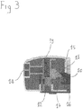
Figure 3 is an enlarged view of certain details of the booster seat for children ofFigure 2 . Referring to the aforementioned figures, a booster seat of the present invention has been generally designated bynumeral 1. - The
booster seat 1 comprises aseat 2 which is designed to accommodate a child. Preferably, thebooster seat 1 also comprises a backrest 3 (as partially shown inFigure 2 ) which may be movable or formed of one piece with theseat 2, and a pair of elbow rests. - The
seat 2 has an inner cavity 5 defined between a top surface of the seat (upon which the child is seated) and a bottom surface, which is designed to contact the seat upon which the booster seat is accommodated.Figure 1 shows the booster seat with the top surface omitted to clearly show the cavity 5 and its contents. - At least one winding drum 6 is located in the cavity 5, and a belt 7 is wound thereupon, with an
end 7a that comes out of the cavity 5 through a slit. Theend 7a of the belt that emerges from the cavity 5 preferably has a free end with an anchor member allowing it to be secured to a complementary anchor member joined to the booster seat, for the belt to form a closed loop. Theend 7a of the belt 7 that emerges from the cavity 5 has the purpose of allowing a chair portion, i.e. a portion of the backrest or the seat of the chair, to be encircled to connect the booster seat to the chair. In the preferred embodiment of the invention, two winding drums 6 are provided, each having its respective belt 7, as shown inFigure 1 . The following description made in relation to one drum and one belt will also apply to the other drum and the other belt. - The drum 6 can rotate about a substantially vertical axis in first and second opposite directions. As used herein, the terms "vertical" and "horizontal" shall be intended in relation to the position of use of the booster seat. The belt 7 is wound around the drum 6 when the latter rotates in the second direction and is unwound from the drum when the latter rotates in the first direction. First elastic members (not shown) act upon the drum 6 to counteract its rotation in the first direction, i.e. to prevent the belt from unwinding. More particularly, the first elastic members wind the belt 7 around the drum 6 when the belt is free to move. In the preferred embodiment of the invention, the first elastic members consist of a torsion spring which directly biases the drum 6.
- The
booster seat 1 also compriseslock members 8 operating on each drum 6 between a retaining position in which they inhibit rotation of the drum and/or movement of the belt, and a release position in which they permit rotation of the drum and/or movement of the belt. Preferably thelock members 8 operate on the belt 7 and comprise a slider 9 which is designed to move between the retaining position, in which the slider 9 mechanically interferes with the belt 7 to inhibit movement thereof, and the release position, in which the slider is moved apart and does not interfere with the belt 7. As shown inFigure 1 , each slider 9 is preferably hinged about a vertical axis to be able to rotate between the retaining position and the release position. Second elastic members 9a operate on the slider 9 to counteract the movement thereof from the release position to the retaining position. Such second elastic members 9a (seeFigure 2 ) consist, for instance, of a torsion spring that acts upon the hinge axis of the slider 9. The second elastic members 9a retain the slider in the position in which the latter retains the belt 7, by pushing the slider 9 against the belt 7 to prevent movement thereof. - The movement of the sliders 9 against the bias of the second elastic members is obtained by a
carriage 10, which is also part of thelock members 8. - The
booster seat 1 further comprisesfirst actuator members 11 operating on thelock members 8 to switch them to the release position. Thefirst actuator members 11 comprise a user-operable pushbutton 12. According to one embodiment, thepushbutton 12 is placed on the bottom surface of theseat 2. Here, it shall be noted that thefirst actuator members 11 cannot be actuated when a child is on the booster seat, as the bottom surface of theseat 2, and hence thepushbutton 12, faces the chair with which the booster seat is coupled and cannot be accessed by the user. This will prevent the lock members from being inadvertently switched to the release position. - The booster seat further comprises
second actuator members 13, operable on saidfirst actuator members 11 and/or on thelock members 8 to switch the latter to the retaining position. In the preferred embodiment of the invention, thesecond actuator members 13 directly operate on thelock members 8, and particularly on thecarriage 10. Thesecond actuator members 13 comprise apushbutton 14 that projects out of a front surface of the seat and is designed to be actuated by a user. Thus, thesecond actuator members 13 can be operated even when the booster seat is in its operating configuration and is accommodating a child. - It will be clear from the above that the first 11 and second 13 actuator members both directly operate on the
lock members 8 and particularly on thecarriage 10, to cause the belts 7 to be unwound and locked respectively. For this purpose, thecarriage 10 is designed to be translated along a direction perpendicular to the axis of rotation of the drums 6. Thecarriage 10 constantly contacts the sliders 9 and overcomes the elastic force of the second elastic members 9a when it is moved by thefirst actuator members 11 to move the sliders 9 away from the belts 7 and allow them to move. - In the preferred embodiment of the invention, the
first actuator members 11 are adapted to be stably switched to a stable unlocked position, in which thelock members 8 are in the release position, and to an inactive position, in which they do not interact with the lock members 8 (seeFigure 2 ). When thefirst actuator members 11 are in the stable unlocked position, the push the carriage 10 (as mentioned above) against the sliders 9 and cause them to rotate against the second elastic members thereby releasing the sliding movement of the belts 7. In order to ensure the stability of this position of thefirst actuator members 11, such that they will constantly bias thecarriage 10, thefirst actuator members 11 comprise a wedge-shaped portion 15. Thecarriage 10 has a wedge-shaped portion 16 substantially mating the shape of the wedge-shaped portion 15 of thefirst actuator members 11. The translation of the latter occurs in a vertical direction, i.e. perpendicular to the sliding direction of thecarriage 10. Therefore, as thepushbutton 12 of thefirst actuator members 11 is actuated, a force with a horizontal component is transmitted to the carriage and translates it (such force being transmitted by the wedge-shaped portion of the first actuator members to the wedge-shaped portion of the carriage). Thefirst actuator members 11 also have ashoulder 17 in the wedge-shaped portion 15 (seeFigure 3 ) which engages the edge of thecarriage 10 having the wedge-shapedportion 16. Particularly, thisshoulder 17 engages acantilever member 18 carried by the wedge-shapedportion 16 of the carriage and abuts it thereby preventing any translation of the pushbutton 12 (seeFigure 3 ). By this arrangement, thefirst actuator members 11 will be in the stable unlocked position. In this position, thefirst actuator members 11, and preferably thepushbutton 12 act against thirdelastic members 19. The latter will tend to move thefirst actuator members 11 back in the inactive position. - The
second actuator members 13 are designed to move between an active position and an inactive position. In the active position, thesecond actuator members 13 break the stability of the stable unlocked position of thefirst actuator members 11, thereby allowing the thirdelastic members 19 to switch thefirst actuator members 11 to the inactive position. When thesecond actuator members 13 are in the active position, the slider 9 is switched to the retaining position (thereby locking the belts 7 in position). Preferably, thesecond actuator members 13 comprise a pushing element 20 (as shown inFigure 1 ) actuated by thepushbutton 14. The pushingmember 20 acts upon thecarriage 10 and translates it further beyond the position it had reached under the action of thefirst actuator members 11. This will cause theshoulder 17 to lose contact with thecantilever member 18 and will allow thepushbutton 12 to be translated under the action of the thirdelastic members 19. The translation of thepushbutton 12 under the action of the thirdelastic members 19 will switch thefirst actuator members 11 to the inactive position. - The return action of fourth
elastic members 21, preferably combined with the action of the second elastic members 9a counteracts the action of the pushingmember 20 and translates thecarriage 10 to the position in which the slider 9 comes to mechanical interference with the belt 7 to prevent movement thereof.
Claims (10)
- A booster seat (1) for children, comprising:a seat (2) having an inner cavity (5);at least one winding drum (6), for a belt (7) to be wound up thereon, said belt (7) having one end (7a) that comes out of said cavity (5) said winding drum (6) being placed in said cavity (5) and being able to rotate in a first direction in which the belt (7) is unwound from the drum (6) and in a second direction in which the belt (7) is wound up on the drum (6);first elastic members, operating on said drum (6) to counteract rotation of said drum (6) in the first direction;lock members (8), operating on said at least one drum (6) and/or said belt (7), and adapted to be switched between a retaining position in which they inhibit rotation of the drum (6) and/or movement of the belt (7), and a release position in which they permit rotation of the drum (6) and/or movement of the belt (7), said first elastic members being configured to wind said belt (7) around said drum (6) when said lock members (8) are in said release position;first actuator members (11), operable on said lock members (8) to switch the lock members (8) to the release position;second actuator members (13), operable on said first actuator members (11) and/or on the lock members (8) to switch the lock members (8) to the retaining position, characterised in that said first actuator members (11) comprise a user-operable pushbutton (12).
- A booster seat as claimed in claim 1, wherein said lock members (8) operate on said belt (7) and comprise a slider (9) designed to move between said retaining position, in which it mechanically interferes with the belt (7) to inhibit movement thereof, and said release position, in which it does not interfere with the belt (7); said lock members (8) further comprising a carriage (10) which contacts said slider (9); said first and second actuator members (11, 13) operating on said carriage (10).
- A booster seat as claimed in claim 1 or 2 wherein said pushbutton (12) is placed on a bottom surface of said seat (2).
- A booster seat as claimed in any of the preceding claims, wherein said second actuator members (13) comprise a pushbutton (14) projecting out of a front surface of said seat (2) and designed to be actuated by a user.
- A booster seat as claimed in claim 2, comprising second elastic members (9a), operating on said carriage (10) and/or said slider (9), and designed to counteract the movement of said slider (9) from the release position to the retaining position.
- A booster seat as claimed in any of the preceding claims, wherein the first actuator members (11) are adapted to be stably switched to a stable unlocked position, in which said lock members (8) are in the release position, and to an inactive position, in which they do not interact with said lock members (8).
- A booster seat as claimed in claims 2 and 6 wherein said first actuator members (11), in said stable unlocked position, counteract said second elastic members (9a) and push said carriage (10) against said slider (9), thereby stably switching said slider to said release position.
- A booster seat as claimed in claim 7, wherein said first actuator members (11), in said stable unlocked position, are in counteracting relationship to third elastic members (19).
- A booster seat as claimed in claim 8, wherein said second actuator members (13) are designed to move between an active position, in which they break the stability of the stable unlocked position of the first actuator members (11), thereby allowing the third elastic members (19) to switch the first actuator members (11) to the inactive position, and an inactive position.
- A booster seat as claimed in claim 9, wherein said second actuator members (13), in the active position, allow the second elastic members (9a) to switch said slider to the retaining position.
Applications Claiming Priority (2)
| Application Number | Priority Date | Filing Date | Title |
|---|---|---|---|
| ITUB2015A009182A ITUB20159182A1 (en) | 2015-12-21 | 2015-12-21 | Booster seat for children. |
| PCT/IB2016/057881 WO2017109723A1 (en) | 2015-12-21 | 2016-12-21 | Booster seat for children |
Publications (2)
| Publication Number | Publication Date |
|---|---|
| EP3393304A1 EP3393304A1 (en) | 2018-10-31 |
| EP3393304B1 true EP3393304B1 (en) | 2019-12-18 |
Family
ID=55642636
Family Applications (1)
| Application Number | Title | Priority Date | Filing Date |
|---|---|---|---|
| EP16834249.1A Active EP3393304B1 (en) | 2015-12-21 | 2016-12-21 | Booster seat for children |
Country Status (6)
| Country | Link |
|---|---|
| US (1) | US10750878B2 (en) |
| EP (1) | EP3393304B1 (en) |
| CN (1) | CN108430274B (en) |
| IT (1) | ITUB20159182A1 (en) |
| PT (1) | PT3393304T (en) |
| WO (1) | WO2017109723A1 (en) |
Families Citing this family (2)
| Publication number | Priority date | Publication date | Assignee | Title |
|---|---|---|---|---|
| US10829011B2 (en) | 2017-06-20 | 2020-11-10 | Graco Children's Products, Inc. | Apparatus and method for a booster seat anchor belt retractor system |
| ES2989078T3 (en) * | 2019-12-27 | 2024-11-25 | Mamas & Papas Holdings Ltd | Booster seats |
Family Cites Families (16)
| Publication number | Priority date | Publication date | Assignee | Title |
|---|---|---|---|---|
| US3612094A (en) * | 1969-05-12 | 1971-10-12 | William R Hare | Remote control hide-away hose |
| JP2749478B2 (en) * | 1992-03-13 | 1998-05-13 | 株式会社東海理化電機製作所 | Child seat |
| DK1204312T3 (en) * | 1999-08-18 | 2003-05-26 | Gerhard Arnold | Rollable dog leash |
| CN201055168Y (en) * | 2007-07-06 | 2008-05-07 | 华敏 | Height-adjustable multifunctional children seat |
| CN201365729Y (en) * | 2008-11-14 | 2009-12-23 | 宝钜实业股份有限公司 | Operating device for child seat and child seat having the same |
| NL1036678C2 (en) * | 2009-03-09 | 2010-09-13 | Maxi Miliaan Bv | Child vehicle seat as well as a base suitable for such a child vehicle seat. |
| CN101844530B (en) * | 2009-03-25 | 2013-03-13 | 明门香港股份有限公司 | Toddler booster chair |
| CN201542158U (en) * | 2009-09-24 | 2010-08-11 | 好孩子儿童用品有限公司 | baby seat |
| AU2010339060B2 (en) * | 2010-01-04 | 2016-06-09 | Steven William Rattenbury | Pivotable infant car seat |
| US8151735B1 (en) * | 2010-02-10 | 2012-04-10 | Paws Aboard, LLC | Leash |
| US8251020B2 (en) * | 2010-03-12 | 2012-08-28 | Unleashed Products, LLC | Leash having a speed-limiting braking mechanism and system and method for using same |
| JP5680975B2 (en) * | 2011-01-13 | 2015-03-04 | アップリカ・チルドレンズプロダクツ合同会社 | Child seat belt lock device and child seat |
| CL2012001772A1 (en) * | 2011-07-01 | 2014-06-06 | Wonderland Nursery Goods | A child seat comprising a seat frame with a back, an anchor band that has an intermediate portion and two end portions respectively provided with two operable fasteners for fixing with an anchor structure of a vehicle, and operable closure . |
| US9480241B2 (en) * | 2011-07-05 | 2016-11-01 | Eric James Holmstrom | Retractable leash system |
| US8967715B2 (en) * | 2011-11-07 | 2015-03-03 | Graco Children's Products Inc. | Anchor latch system for child restraint systems and child car safety seats |
| US9717218B2 (en) * | 2012-09-05 | 2017-08-01 | Doskocil Manufacturing Company, Inc. | Retractable leash |
-
2015
- 2015-12-21 IT ITUB2015A009182A patent/ITUB20159182A1/en unknown
-
2016
- 2016-12-21 WO PCT/IB2016/057881 patent/WO2017109723A1/en not_active Ceased
- 2016-12-21 US US16/062,643 patent/US10750878B2/en not_active Expired - Fee Related
- 2016-12-21 CN CN201680075264.0A patent/CN108430274B/en active Active
- 2016-12-21 EP EP16834249.1A patent/EP3393304B1/en active Active
- 2016-12-21 PT PT168342491T patent/PT3393304T/en unknown
Non-Patent Citations (1)
| Title |
|---|
| None * |
Also Published As
| Publication number | Publication date |
|---|---|
| CN108430274B (en) | 2022-03-25 |
| US20180360229A1 (en) | 2018-12-20 |
| US10750878B2 (en) | 2020-08-25 |
| WO2017109723A1 (en) | 2017-06-29 |
| PT3393304T (en) | 2020-03-25 |
| CN108430274A (en) | 2018-08-21 |
| ITUB20159182A1 (en) | 2017-06-21 |
| EP3393304A1 (en) | 2018-10-31 |
Similar Documents
| Publication | Publication Date | Title |
|---|---|---|
| EP2952408B1 (en) | Stroller frame assembly | |
| CA2763903C (en) | Child safety seat assembly | |
| KR101692906B1 (en) | Forward and rearward facing child seat with belt tensioning mechanism for improved installation | |
| US6935696B2 (en) | Head restraint mechanism and method of making same | |
| US8714639B2 (en) | Infant carrier with handle | |
| US20150201814A1 (en) | Bath chair | |
| US8215661B2 (en) | Stroller | |
| US20150001873A2 (en) | Storage structure for vehicle | |
| GB2517288A (en) | Joint device | |
| GB2480356A (en) | A latch device adapted for coupling a baby carrier to a stroller | |
| BRPI1103457A2 (en) | child safety seat set | |
| GB2517268A (en) | Child seat convertible to multiple configurations of use | |
| JP3242232U (en) | Buckle mechanism | |
| JP6747918B2 (en) | stroller | |
| US10750878B2 (en) | Booster seats for children | |
| CN106494276A (en) | baby carrier | |
| CN104185589B (en) | Stroller | |
| JP4966095B2 (en) | Hinge mechanism | |
| JP3201636U (en) | child seat | |
| US10786092B1 (en) | Foldable baby carrier | |
| WO2006016119A3 (en) | Power plug or adaptor with retractable/foldable pins | |
| JP2009202776A (en) | Caster lock mechanism and folding table | |
| JP2010104420A (en) | Chair for musical instrument | |
| KR20190016566A (en) | Shaft support structure of pivot body | |
| JP7221793B2 (en) | bathroom chair |
Legal Events
| Date | Code | Title | Description |
|---|---|---|---|
| STAA | Information on the status of an ep patent application or granted ep patent |
Free format text: STATUS: UNKNOWN |
|
| STAA | Information on the status of an ep patent application or granted ep patent |
Free format text: STATUS: THE INTERNATIONAL PUBLICATION HAS BEEN MADE |
|
| PUAI | Public reference made under article 153(3) epc to a published international application that has entered the european phase |
Free format text: ORIGINAL CODE: 0009012 |
|
| STAA | Information on the status of an ep patent application or granted ep patent |
Free format text: STATUS: REQUEST FOR EXAMINATION WAS MADE |
|
| 17P | Request for examination filed |
Effective date: 20180607 |
|
| AK | Designated contracting states |
Kind code of ref document: A1 Designated state(s): AL AT BE BG CH CY CZ DE DK EE ES FI FR GB GR HR HU IE IS IT LI LT LU LV MC MK MT NL NO PL PT RO RS SE SI SK SM TR |
|
| AX | Request for extension of the european patent |
Extension state: BA ME |
|
| DAV | Request for validation of the european patent (deleted) | ||
| DAX | Request for extension of the european patent (deleted) | ||
| REG | Reference to a national code |
Ref country code: DE Ref legal event code: R079 Ref document number: 602016026612 Country of ref document: DE Free format text: PREVIOUS MAIN CLASS: A47D0001100000 Ipc: B65H0075440000 |
|
| GRAP | Despatch of communication of intention to grant a patent |
Free format text: ORIGINAL CODE: EPIDOSNIGR1 |
|
| STAA | Information on the status of an ep patent application or granted ep patent |
Free format text: STATUS: GRANT OF PATENT IS INTENDED |
|
| RIC1 | Information provided on ipc code assigned before grant |
Ipc: B65H 75/44 20060101AFI20190606BHEP Ipc: A47D 1/10 20060101ALI20190606BHEP Ipc: B65H 75/48 20060101ALI20190606BHEP |
|
| INTG | Intention to grant announced |
Effective date: 20190703 |
|
| GRAS | Grant fee paid |
Free format text: ORIGINAL CODE: EPIDOSNIGR3 |
|
| GRAA | (expected) grant |
Free format text: ORIGINAL CODE: 0009210 |
|
| STAA | Information on the status of an ep patent application or granted ep patent |
Free format text: STATUS: THE PATENT HAS BEEN GRANTED |
|
| AK | Designated contracting states |
Kind code of ref document: B1 Designated state(s): AL AT BE BG CH CY CZ DE DK EE ES FI FR GB GR HR HU IE IS IT LI LT LU LV MC MK MT NL NO PL PT RO RS SE SI SK SM TR |
|
| REG | Reference to a national code |
Ref country code: HK Ref legal event code: DE Ref document number: 1260459 Country of ref document: HK |
|
| REG | Reference to a national code |
Ref country code: CH Ref legal event code: EP |
|
| REG | Reference to a national code |
Ref country code: IE Ref legal event code: FG4D |
|
| REG | Reference to a national code |
Ref country code: DE Ref legal event code: R096 Ref document number: 602016026612 Country of ref document: DE |
|
| REG | Reference to a national code |
Ref country code: AT Ref legal event code: REF Ref document number: 1214387 Country of ref document: AT Kind code of ref document: T Effective date: 20200115 |
|
| REG | Reference to a national code |
Ref country code: PT Ref legal event code: SC4A Ref document number: 3393304 Country of ref document: PT Date of ref document: 20200325 Kind code of ref document: T Free format text: AVAILABILITY OF NATIONAL TRANSLATION Effective date: 20200313 |
|
| REG | Reference to a national code |
Ref country code: NL Ref legal event code: MP Effective date: 20191218 |
|
| PG25 | Lapsed in a contracting state [announced via postgrant information from national office to epo] |
Ref country code: LT Free format text: LAPSE BECAUSE OF FAILURE TO SUBMIT A TRANSLATION OF THE DESCRIPTION OR TO PAY THE FEE WITHIN THE PRESCRIBED TIME-LIMIT Effective date: 20191218 Ref country code: SE Free format text: LAPSE BECAUSE OF FAILURE TO SUBMIT A TRANSLATION OF THE DESCRIPTION OR TO PAY THE FEE WITHIN THE PRESCRIBED TIME-LIMIT Effective date: 20191218 Ref country code: BG Free format text: LAPSE BECAUSE OF FAILURE TO SUBMIT A TRANSLATION OF THE DESCRIPTION OR TO PAY THE FEE WITHIN THE PRESCRIBED TIME-LIMIT Effective date: 20200318 Ref country code: LV Free format text: LAPSE BECAUSE OF FAILURE TO SUBMIT A TRANSLATION OF THE DESCRIPTION OR TO PAY THE FEE WITHIN THE PRESCRIBED TIME-LIMIT Effective date: 20191218 Ref country code: GR Free format text: LAPSE BECAUSE OF FAILURE TO SUBMIT A TRANSLATION OF THE DESCRIPTION OR TO PAY THE FEE WITHIN THE PRESCRIBED TIME-LIMIT Effective date: 20200319 Ref country code: NO Free format text: LAPSE BECAUSE OF FAILURE TO SUBMIT A TRANSLATION OF THE DESCRIPTION OR TO PAY THE FEE WITHIN THE PRESCRIBED TIME-LIMIT Effective date: 20200318 Ref country code: FI Free format text: LAPSE BECAUSE OF FAILURE TO SUBMIT A TRANSLATION OF THE DESCRIPTION OR TO PAY THE FEE WITHIN THE PRESCRIBED TIME-LIMIT Effective date: 20191218 |
|
| REG | Reference to a national code |
Ref country code: LT Ref legal event code: MG4D |
|
| PG25 | Lapsed in a contracting state [announced via postgrant information from national office to epo] |
Ref country code: RS Free format text: LAPSE BECAUSE OF FAILURE TO SUBMIT A TRANSLATION OF THE DESCRIPTION OR TO PAY THE FEE WITHIN THE PRESCRIBED TIME-LIMIT Effective date: 20191218 Ref country code: HR Free format text: LAPSE BECAUSE OF FAILURE TO SUBMIT A TRANSLATION OF THE DESCRIPTION OR TO PAY THE FEE WITHIN THE PRESCRIBED TIME-LIMIT Effective date: 20191218 |
|
| PG25 | Lapsed in a contracting state [announced via postgrant information from national office to epo] |
Ref country code: AL Free format text: LAPSE BECAUSE OF FAILURE TO SUBMIT A TRANSLATION OF THE DESCRIPTION OR TO PAY THE FEE WITHIN THE PRESCRIBED TIME-LIMIT Effective date: 20191218 |
|
| REG | Reference to a national code |
Ref country code: DE Ref legal event code: R119 Ref document number: 602016026612 Country of ref document: DE |
|
| PG25 | Lapsed in a contracting state [announced via postgrant information from national office to epo] |
Ref country code: EE Free format text: LAPSE BECAUSE OF FAILURE TO SUBMIT A TRANSLATION OF THE DESCRIPTION OR TO PAY THE FEE WITHIN THE PRESCRIBED TIME-LIMIT Effective date: 20191218 Ref country code: RO Free format text: LAPSE BECAUSE OF FAILURE TO SUBMIT A TRANSLATION OF THE DESCRIPTION OR TO PAY THE FEE WITHIN THE PRESCRIBED TIME-LIMIT Effective date: 20191218 Ref country code: NL Free format text: LAPSE BECAUSE OF FAILURE TO SUBMIT A TRANSLATION OF THE DESCRIPTION OR TO PAY THE FEE WITHIN THE PRESCRIBED TIME-LIMIT Effective date: 20191218 Ref country code: CZ Free format text: LAPSE BECAUSE OF FAILURE TO SUBMIT A TRANSLATION OF THE DESCRIPTION OR TO PAY THE FEE WITHIN THE PRESCRIBED TIME-LIMIT Effective date: 20191218 |
|
| REG | Reference to a national code |
Ref country code: CH Ref legal event code: PL |
|
| PG25 | Lapsed in a contracting state [announced via postgrant information from national office to epo] |
Ref country code: IS Free format text: LAPSE BECAUSE OF FAILURE TO SUBMIT A TRANSLATION OF THE DESCRIPTION OR TO PAY THE FEE WITHIN THE PRESCRIBED TIME-LIMIT Effective date: 20200418 Ref country code: SK Free format text: LAPSE BECAUSE OF FAILURE TO SUBMIT A TRANSLATION OF THE DESCRIPTION OR TO PAY THE FEE WITHIN THE PRESCRIBED TIME-LIMIT Effective date: 20191218 Ref country code: SM Free format text: LAPSE BECAUSE OF FAILURE TO SUBMIT A TRANSLATION OF THE DESCRIPTION OR TO PAY THE FEE WITHIN THE PRESCRIBED TIME-LIMIT Effective date: 20191218 |
|
| PG25 | Lapsed in a contracting state [announced via postgrant information from national office to epo] |
Ref country code: MC Free format text: LAPSE BECAUSE OF FAILURE TO SUBMIT A TRANSLATION OF THE DESCRIPTION OR TO PAY THE FEE WITHIN THE PRESCRIBED TIME-LIMIT Effective date: 20191218 |
|
| REG | Reference to a national code |
Ref country code: AT Ref legal event code: MK05 Ref document number: 1214387 Country of ref document: AT Kind code of ref document: T Effective date: 20191218 |
|
| PLBE | No opposition filed within time limit |
Free format text: ORIGINAL CODE: 0009261 |
|
| STAA | Information on the status of an ep patent application or granted ep patent |
Free format text: STATUS: NO OPPOSITION FILED WITHIN TIME LIMIT |
|
| PG25 | Lapsed in a contracting state [announced via postgrant information from national office to epo] |
Ref country code: DK Free format text: LAPSE BECAUSE OF FAILURE TO SUBMIT A TRANSLATION OF THE DESCRIPTION OR TO PAY THE FEE WITHIN THE PRESCRIBED TIME-LIMIT Effective date: 20191218 Ref country code: IE Free format text: LAPSE BECAUSE OF NON-PAYMENT OF DUE FEES Effective date: 20191221 Ref country code: DE Free format text: LAPSE BECAUSE OF NON-PAYMENT OF DUE FEES Effective date: 20200701 Ref country code: ES Free format text: LAPSE BECAUSE OF FAILURE TO SUBMIT A TRANSLATION OF THE DESCRIPTION OR TO PAY THE FEE WITHIN THE PRESCRIBED TIME-LIMIT Effective date: 20191218 Ref country code: LU Free format text: LAPSE BECAUSE OF NON-PAYMENT OF DUE FEES Effective date: 20191221 |
|
| 26N | No opposition filed |
Effective date: 20200921 |
|
| PG25 | Lapsed in a contracting state [announced via postgrant information from national office to epo] |
Ref country code: AT Free format text: LAPSE BECAUSE OF FAILURE TO SUBMIT A TRANSLATION OF THE DESCRIPTION OR TO PAY THE FEE WITHIN THE PRESCRIBED TIME-LIMIT Effective date: 20191218 Ref country code: LI Free format text: LAPSE BECAUSE OF NON-PAYMENT OF DUE FEES Effective date: 20191231 Ref country code: CH Free format text: LAPSE BECAUSE OF NON-PAYMENT OF DUE FEES Effective date: 20191231 Ref country code: SI Free format text: LAPSE BECAUSE OF FAILURE TO SUBMIT A TRANSLATION OF THE DESCRIPTION OR TO PAY THE FEE WITHIN THE PRESCRIBED TIME-LIMIT Effective date: 20191218 |
|
| PGFP | Annual fee paid to national office [announced via postgrant information from national office to epo] |
Ref country code: PT Payment date: 20201218 Year of fee payment: 5 Ref country code: GB Payment date: 20201223 Year of fee payment: 5 |
|
| PG25 | Lapsed in a contracting state [announced via postgrant information from national office to epo] |
Ref country code: PL Free format text: LAPSE BECAUSE OF FAILURE TO SUBMIT A TRANSLATION OF THE DESCRIPTION OR TO PAY THE FEE WITHIN THE PRESCRIBED TIME-LIMIT Effective date: 20191218 |
|
| PGFP | Annual fee paid to national office [announced via postgrant information from national office to epo] |
Ref country code: BE Payment date: 20201221 Year of fee payment: 5 |
|
| PG25 | Lapsed in a contracting state [announced via postgrant information from national office to epo] |
Ref country code: CY Free format text: LAPSE BECAUSE OF FAILURE TO SUBMIT A TRANSLATION OF THE DESCRIPTION OR TO PAY THE FEE WITHIN THE PRESCRIBED TIME-LIMIT Effective date: 20191218 |
|
| PG25 | Lapsed in a contracting state [announced via postgrant information from national office to epo] |
Ref country code: MT Free format text: LAPSE BECAUSE OF FAILURE TO SUBMIT A TRANSLATION OF THE DESCRIPTION OR TO PAY THE FEE WITHIN THE PRESCRIBED TIME-LIMIT Effective date: 20191218 Ref country code: HU Free format text: LAPSE BECAUSE OF FAILURE TO SUBMIT A TRANSLATION OF THE DESCRIPTION OR TO PAY THE FEE WITHIN THE PRESCRIBED TIME-LIMIT; INVALID AB INITIO Effective date: 20161221 |
|
| PG25 | Lapsed in a contracting state [announced via postgrant information from national office to epo] |
Ref country code: TR Free format text: LAPSE BECAUSE OF FAILURE TO SUBMIT A TRANSLATION OF THE DESCRIPTION OR TO PAY THE FEE WITHIN THE PRESCRIBED TIME-LIMIT Effective date: 20191218 |
|
| PG25 | Lapsed in a contracting state [announced via postgrant information from national office to epo] |
Ref country code: MK Free format text: LAPSE BECAUSE OF FAILURE TO SUBMIT A TRANSLATION OF THE DESCRIPTION OR TO PAY THE FEE WITHIN THE PRESCRIBED TIME-LIMIT Effective date: 20191218 |
|
| PG25 | Lapsed in a contracting state [announced via postgrant information from national office to epo] |
Ref country code: PT Free format text: LAPSE BECAUSE OF NON-PAYMENT OF DUE FEES Effective date: 20220621 |
|
| GBPC | Gb: european patent ceased through non-payment of renewal fee |
Effective date: 20211221 |
|
| REG | Reference to a national code |
Ref country code: BE Ref legal event code: MM Effective date: 20211231 |
|
| PG25 | Lapsed in a contracting state [announced via postgrant information from national office to epo] |
Ref country code: GB Free format text: LAPSE BECAUSE OF NON-PAYMENT OF DUE FEES Effective date: 20211221 |
|
| PG25 | Lapsed in a contracting state [announced via postgrant information from national office to epo] |
Ref country code: BE Free format text: LAPSE BECAUSE OF NON-PAYMENT OF DUE FEES Effective date: 20211231 |
|
| PGFP | Annual fee paid to national office [announced via postgrant information from national office to epo] |
Ref country code: FR Payment date: 20221222 Year of fee payment: 7 |
|
| P01 | Opt-out of the competence of the unified patent court (upc) registered |
Effective date: 20230602 |
|
| P02 | Opt-out of the competence of the unified patent court (upc) changed |
Effective date: 20230726 |
|
| P02 | Opt-out of the competence of the unified patent court (upc) changed |
Effective date: 20230816 |
|
| PG25 | Lapsed in a contracting state [announced via postgrant information from national office to epo] |
Ref country code: FR Free format text: LAPSE BECAUSE OF NON-PAYMENT OF DUE FEES Effective date: 20231231 |
|
| PG25 | Lapsed in a contracting state [announced via postgrant information from national office to epo] |
Ref country code: FR Free format text: LAPSE BECAUSE OF NON-PAYMENT OF DUE FEES Effective date: 20231231 |
|
| REG | Reference to a national code |
Ref country code: HK Ref legal event code: WD Ref document number: 1260459 Country of ref document: HK |
|
| PGFP | Annual fee paid to national office [announced via postgrant information from national office to epo] |
Ref country code: IT Payment date: 20251212 Year of fee payment: 10 |