EP3393219A1 - Ventilation and humidity-conditioning unit, and equipment - Google Patents
Ventilation and humidity-conditioning unit, and equipment Download PDFInfo
- Publication number
- EP3393219A1 EP3393219A1 EP16875580.9A EP16875580A EP3393219A1 EP 3393219 A1 EP3393219 A1 EP 3393219A1 EP 16875580 A EP16875580 A EP 16875580A EP 3393219 A1 EP3393219 A1 EP 3393219A1
- Authority
- EP
- European Patent Office
- Prior art keywords
- humidity
- ventilation
- conditioning
- housing
- internal space
- Prior art date
- Legal status (The legal status is an assumption and is not a legal conclusion. Google has not performed a legal analysis and makes no representation as to the accuracy of the status listed.)
- Withdrawn
Links
- 238000009423 ventilation Methods 0.000 title claims abstract description 243
- XLYOFNOQVPJJNP-UHFFFAOYSA-N water Chemical compound O XLYOFNOQVPJJNP-UHFFFAOYSA-N 0.000 claims abstract description 62
- 239000007788 liquid Substances 0.000 claims abstract description 11
- 238000010521 absorption reaction Methods 0.000 claims description 16
- 239000007787 solid Substances 0.000 claims description 8
- 238000002474 experimental method Methods 0.000 description 27
- 230000003578 releasing effect Effects 0.000 description 26
- 239000000463 material Substances 0.000 description 22
- 239000004745 nonwoven fabric Substances 0.000 description 12
- 238000000034 method Methods 0.000 description 11
- 238000010586 diagram Methods 0.000 description 10
- 238000009833 condensation Methods 0.000 description 9
- 230000005494 condensation Effects 0.000 description 9
- 230000003247 decreasing effect Effects 0.000 description 9
- 239000000428 dust Substances 0.000 description 7
- 239000000835 fiber Substances 0.000 description 7
- 239000005871 repellent Substances 0.000 description 7
- 239000002759 woven fabric Substances 0.000 description 7
- 230000007423 decrease Effects 0.000 description 6
- 230000000694 effects Effects 0.000 description 6
- 229920001343 polytetrafluoroethylene Polymers 0.000 description 4
- 239000004810 polytetrafluoroethylene Substances 0.000 description 4
- ODINCKMPIJJUCX-UHFFFAOYSA-N Calcium oxide Chemical compound [Ca]=O ODINCKMPIJJUCX-UHFFFAOYSA-N 0.000 description 2
- TWRXJAOTZQYOKJ-UHFFFAOYSA-L Magnesium chloride Chemical compound [Mg+2].[Cl-].[Cl-] TWRXJAOTZQYOKJ-UHFFFAOYSA-L 0.000 description 2
- VYPSYNLAJGMNEJ-UHFFFAOYSA-N Silicium dioxide Chemical compound O=[Si]=O VYPSYNLAJGMNEJ-UHFFFAOYSA-N 0.000 description 2
- 239000000853 adhesive Substances 0.000 description 2
- 230000001070 adhesive effect Effects 0.000 description 2
- 239000003795 chemical substances by application Substances 0.000 description 2
- 230000006866 deterioration Effects 0.000 description 2
- 239000003292 glue Substances 0.000 description 2
- 238000005259 measurement Methods 0.000 description 2
- 229920000728 polyester Polymers 0.000 description 2
- -1 polytetrafluoroethylene Polymers 0.000 description 2
- 229920006395 saturated elastomer Polymers 0.000 description 2
- 239000000741 silica gel Substances 0.000 description 2
- 229910002027 silica gel Inorganic materials 0.000 description 2
- 238000003466 welding Methods 0.000 description 2
- NWUYHJFMYQTDRP-UHFFFAOYSA-N 1,2-bis(ethenyl)benzene;1-ethenyl-2-ethylbenzene;styrene Chemical compound C=CC1=CC=CC=C1.CCC1=CC=CC=C1C=C.C=CC1=CC=CC=C1C=C NWUYHJFMYQTDRP-UHFFFAOYSA-N 0.000 description 1
- NIXOWILDQLNWCW-UHFFFAOYSA-M Acrylate Chemical compound [O-]C(=O)C=C NIXOWILDQLNWCW-UHFFFAOYSA-M 0.000 description 1
- 229920002972 Acrylic fiber Polymers 0.000 description 1
- UXVMQQNJUSDDNG-UHFFFAOYSA-L Calcium chloride Chemical compound [Cl-].[Cl-].[Ca+2] UXVMQQNJUSDDNG-UHFFFAOYSA-L 0.000 description 1
- PXGOKWXKJXAPGV-UHFFFAOYSA-N Fluorine Chemical compound FF PXGOKWXKJXAPGV-UHFFFAOYSA-N 0.000 description 1
- 239000004698 Polyethylene Substances 0.000 description 1
- 229910021536 Zeolite Inorganic materials 0.000 description 1
- 230000002745 absorbent Effects 0.000 description 1
- 239000002250 absorbent Substances 0.000 description 1
- 230000002378 acidificating effect Effects 0.000 description 1
- NIXOWILDQLNWCW-UHFFFAOYSA-N acrylic acid group Chemical group C(C=C)(=O)O NIXOWILDQLNWCW-UHFFFAOYSA-N 0.000 description 1
- 239000001110 calcium chloride Substances 0.000 description 1
- 229910001628 calcium chloride Inorganic materials 0.000 description 1
- 239000000292 calcium oxide Substances 0.000 description 1
- 235000012255 calcium oxide Nutrition 0.000 description 1
- 125000003178 carboxy group Chemical group [H]OC(*)=O 0.000 description 1
- 239000004927 clay Substances 0.000 description 1
- 229910052570 clay Inorganic materials 0.000 description 1
- 150000001875 compounds Chemical class 0.000 description 1
- 238000004925 denaturation Methods 0.000 description 1
- 230000036425 denaturation Effects 0.000 description 1
- HNPSIPDUKPIQMN-UHFFFAOYSA-N dioxosilane;oxo(oxoalumanyloxy)alumane Chemical compound O=[Si]=O.O=[Al]O[Al]=O HNPSIPDUKPIQMN-UHFFFAOYSA-N 0.000 description 1
- 238000007598 dipping method Methods 0.000 description 1
- 238000000605 extraction Methods 0.000 description 1
- 239000004744 fabric Substances 0.000 description 1
- 229910052731 fluorine Inorganic materials 0.000 description 1
- 239000011737 fluorine Substances 0.000 description 1
- 230000004927 fusion Effects 0.000 description 1
- 238000007756 gravure coating Methods 0.000 description 1
- 230000020169 heat generation Effects 0.000 description 1
- 125000001183 hydrocarbyl group Chemical group 0.000 description 1
- 230000003301 hydrolyzing effect Effects 0.000 description 1
- 239000003456 ion exchange resin Substances 0.000 description 1
- 229920003303 ion-exchange polymer Polymers 0.000 description 1
- 238000007759 kiss coating Methods 0.000 description 1
- 238000010030 laminating Methods 0.000 description 1
- 229910001629 magnesium chloride Inorganic materials 0.000 description 1
- 238000002844 melting Methods 0.000 description 1
- 230000008018 melting Effects 0.000 description 1
- QSHDDOUJBYECFT-UHFFFAOYSA-N mercury Chemical compound [Hg] QSHDDOUJBYECFT-UHFFFAOYSA-N 0.000 description 1
- 229910052753 mercury Inorganic materials 0.000 description 1
- 125000005395 methacrylic acid group Chemical group 0.000 description 1
- 239000000203 mixture Substances 0.000 description 1
- 230000003287 optical effect Effects 0.000 description 1
- 230000035515 penetration Effects 0.000 description 1
- 125000005010 perfluoroalkyl group Chemical group 0.000 description 1
- 239000004033 plastic Substances 0.000 description 1
- 229920003023 plastic Polymers 0.000 description 1
- 229920000573 polyethylene Polymers 0.000 description 1
- 229920000098 polyolefin Polymers 0.000 description 1
- 229920001296 polysiloxane Polymers 0.000 description 1
- 125000001453 quaternary ammonium group Chemical group 0.000 description 1
- 229920005989 resin Polymers 0.000 description 1
- 239000011347 resin Substances 0.000 description 1
- 150000003839 salts Chemical class 0.000 description 1
- 238000005507 spraying Methods 0.000 description 1
- 125000001273 sulfonato group Chemical group [O-]S(*)(=O)=O 0.000 description 1
- 238000009823 thermal lamination Methods 0.000 description 1
- 229920002725 thermoplastic elastomer Polymers 0.000 description 1
- 229920005992 thermoplastic resin Polymers 0.000 description 1
- 239000010457 zeolite Substances 0.000 description 1
Images



Classifications
-
- F—MECHANICAL ENGINEERING; LIGHTING; HEATING; WEAPONS; BLASTING
- F21—LIGHTING
- F21V—FUNCTIONAL FEATURES OR DETAILS OF LIGHTING DEVICES OR SYSTEMS THEREOF; STRUCTURAL COMBINATIONS OF LIGHTING DEVICES WITH OTHER ARTICLES, NOT OTHERWISE PROVIDED FOR
- F21V31/00—Gas-tight or water-tight arrangements
- F21V31/03—Gas-tight or water-tight arrangements with provision for venting
-
- B—PERFORMING OPERATIONS; TRANSPORTING
- B01—PHYSICAL OR CHEMICAL PROCESSES OR APPARATUS IN GENERAL
- B01D—SEPARATION
- B01D53/00—Separation of gases or vapours; Recovering vapours of volatile solvents from gases; Chemical or biological purification of waste gases, e.g. engine exhaust gases, smoke, fumes, flue gases, aerosols
- B01D53/26—Drying gases or vapours
- B01D53/261—Drying gases or vapours by adsorption
-
- B—PERFORMING OPERATIONS; TRANSPORTING
- B01—PHYSICAL OR CHEMICAL PROCESSES OR APPARATUS IN GENERAL
- B01D—SEPARATION
- B01D53/00—Separation of gases or vapours; Recovering vapours of volatile solvents from gases; Chemical or biological purification of waste gases, e.g. engine exhaust gases, smoke, fumes, flue gases, aerosols
- B01D53/26—Drying gases or vapours
- B01D53/263—Drying gases or vapours by absorption
-
- B—PERFORMING OPERATIONS; TRANSPORTING
- B01—PHYSICAL OR CHEMICAL PROCESSES OR APPARATUS IN GENERAL
- B01D—SEPARATION
- B01D53/00—Separation of gases or vapours; Recovering vapours of volatile solvents from gases; Chemical or biological purification of waste gases, e.g. engine exhaust gases, smoke, fumes, flue gases, aerosols
- B01D53/26—Drying gases or vapours
- B01D53/268—Drying gases or vapours by diffusion
-
- F—MECHANICAL ENGINEERING; LIGHTING; HEATING; WEAPONS; BLASTING
- F21—LIGHTING
- F21S—NON-PORTABLE LIGHTING DEVICES; SYSTEMS THEREOF; VEHICLE LIGHTING DEVICES SPECIALLY ADAPTED FOR VEHICLE EXTERIORS
- F21S45/00—Arrangements within vehicle lighting devices specially adapted for vehicle exteriors, for purposes other than emission or distribution of light
- F21S45/10—Protection of lighting devices
-
- F—MECHANICAL ENGINEERING; LIGHTING; HEATING; WEAPONS; BLASTING
- F21—LIGHTING
- F21S—NON-PORTABLE LIGHTING DEVICES; SYSTEMS THEREOF; VEHICLE LIGHTING DEVICES SPECIALLY ADAPTED FOR VEHICLE EXTERIORS
- F21S45/00—Arrangements within vehicle lighting devices specially adapted for vehicle exteriors, for purposes other than emission or distribution of light
- F21S45/30—Ventilation or drainage of lighting devices
- F21S45/33—Ventilation or drainage of lighting devices specially adapted for headlamps
-
- F—MECHANICAL ENGINEERING; LIGHTING; HEATING; WEAPONS; BLASTING
- F21—LIGHTING
- F21S—NON-PORTABLE LIGHTING DEVICES; SYSTEMS THEREOF; VEHICLE LIGHTING DEVICES SPECIALLY ADAPTED FOR VEHICLE EXTERIORS
- F21S45/00—Arrangements within vehicle lighting devices specially adapted for vehicle exteriors, for purposes other than emission or distribution of light
- F21S45/50—Waterproofing
-
- F—MECHANICAL ENGINEERING; LIGHTING; HEATING; WEAPONS; BLASTING
- F21—LIGHTING
- F21V—FUNCTIONAL FEATURES OR DETAILS OF LIGHTING DEVICES OR SYSTEMS THEREOF; STRUCTURAL COMBINATIONS OF LIGHTING DEVICES WITH OTHER ARTICLES, NOT OTHERWISE PROVIDED FOR
- F21V31/00—Gas-tight or water-tight arrangements
- F21V31/005—Sealing arrangements therefor
-
- H—ELECTRICITY
- H05—ELECTRIC TECHNIQUES NOT OTHERWISE PROVIDED FOR
- H05K—PRINTED CIRCUITS; CASINGS OR CONSTRUCTIONAL DETAILS OF ELECTRIC APPARATUS; MANUFACTURE OF ASSEMBLAGES OF ELECTRICAL COMPONENTS
- H05K5/00—Casings, cabinets or drawers for electric apparatus
- H05K5/06—Hermetically-sealed casings
-
- B—PERFORMING OPERATIONS; TRANSPORTING
- B01—PHYSICAL OR CHEMICAL PROCESSES OR APPARATUS IN GENERAL
- B01D—SEPARATION
- B01D2251/00—Reactants
- B01D2251/40—Alkaline earth metal or magnesium compounds
- B01D2251/402—Alkaline earth metal or magnesium compounds of magnesium
-
- B—PERFORMING OPERATIONS; TRANSPORTING
- B01—PHYSICAL OR CHEMICAL PROCESSES OR APPARATUS IN GENERAL
- B01D—SEPARATION
- B01D2251/00—Reactants
- B01D2251/40—Alkaline earth metal or magnesium compounds
- B01D2251/404—Alkaline earth metal or magnesium compounds of calcium
-
- B—PERFORMING OPERATIONS; TRANSPORTING
- B01—PHYSICAL OR CHEMICAL PROCESSES OR APPARATUS IN GENERAL
- B01D—SEPARATION
- B01D2251/00—Reactants
- B01D2251/60—Inorganic bases or salts
-
- B—PERFORMING OPERATIONS; TRANSPORTING
- B01—PHYSICAL OR CHEMICAL PROCESSES OR APPARATUS IN GENERAL
- B01D—SEPARATION
- B01D2251/00—Reactants
- B01D2251/60—Inorganic bases or salts
- B01D2251/602—Oxides
-
- B—PERFORMING OPERATIONS; TRANSPORTING
- B01—PHYSICAL OR CHEMICAL PROCESSES OR APPARATUS IN GENERAL
- B01D—SEPARATION
- B01D2253/00—Adsorbents used in seperation treatment of gases and vapours
- B01D2253/10—Inorganic adsorbents
- B01D2253/106—Silica or silicates
-
- B—PERFORMING OPERATIONS; TRANSPORTING
- B01—PHYSICAL OR CHEMICAL PROCESSES OR APPARATUS IN GENERAL
- B01D—SEPARATION
- B01D2253/00—Adsorbents used in seperation treatment of gases and vapours
- B01D2253/10—Inorganic adsorbents
- B01D2253/106—Silica or silicates
- B01D2253/108—Zeolites
-
- B—PERFORMING OPERATIONS; TRANSPORTING
- B01—PHYSICAL OR CHEMICAL PROCESSES OR APPARATUS IN GENERAL
- B01D—SEPARATION
- B01D2253/00—Adsorbents used in seperation treatment of gases and vapours
- B01D2253/10—Inorganic adsorbents
- B01D2253/106—Silica or silicates
- B01D2253/11—Clays
-
- B—PERFORMING OPERATIONS; TRANSPORTING
- B01—PHYSICAL OR CHEMICAL PROCESSES OR APPARATUS IN GENERAL
- B01D—SEPARATION
- B01D2259/00—Type of treatment
- B01D2259/45—Gas separation or purification devices adapted for specific applications
- B01D2259/4508—Gas separation or purification devices adapted for specific applications for cleaning air in buildings
-
- F—MECHANICAL ENGINEERING; LIGHTING; HEATING; WEAPONS; BLASTING
- F21—LIGHTING
- F21S—NON-PORTABLE LIGHTING DEVICES; SYSTEMS THEREOF; VEHICLE LIGHTING DEVICES SPECIALLY ADAPTED FOR VEHICLE EXTERIORS
- F21S41/00—Illuminating devices specially adapted for vehicle exteriors, e.g. headlamps
- F21S41/10—Illuminating devices specially adapted for vehicle exteriors, e.g. headlamps characterised by the light source
- F21S41/14—Illuminating devices specially adapted for vehicle exteriors, e.g. headlamps characterised by the light source characterised by the type of light source
- F21S41/141—Light emitting diodes [LED]
- F21S41/147—Light emitting diodes [LED] the main emission direction of the LED being angled to the optical axis of the illuminating device
- F21S41/148—Light emitting diodes [LED] the main emission direction of the LED being angled to the optical axis of the illuminating device the main emission direction of the LED being perpendicular to the optical axis
-
- F—MECHANICAL ENGINEERING; LIGHTING; HEATING; WEAPONS; BLASTING
- F21—LIGHTING
- F21S—NON-PORTABLE LIGHTING DEVICES; SYSTEMS THEREOF; VEHICLE LIGHTING DEVICES SPECIALLY ADAPTED FOR VEHICLE EXTERIORS
- F21S41/00—Illuminating devices specially adapted for vehicle exteriors, e.g. headlamps
- F21S41/20—Illuminating devices specially adapted for vehicle exteriors, e.g. headlamps characterised by refractors, transparent cover plates, light guides or filters
- F21S41/25—Projection lenses
-
- F—MECHANICAL ENGINEERING; LIGHTING; HEATING; WEAPONS; BLASTING
- F21—LIGHTING
- F21S—NON-PORTABLE LIGHTING DEVICES; SYSTEMS THEREOF; VEHICLE LIGHTING DEVICES SPECIALLY ADAPTED FOR VEHICLE EXTERIORS
- F21S41/00—Illuminating devices specially adapted for vehicle exteriors, e.g. headlamps
- F21S41/20—Illuminating devices specially adapted for vehicle exteriors, e.g. headlamps characterised by refractors, transparent cover plates, light guides or filters
- F21S41/28—Cover glass
-
- F—MECHANICAL ENGINEERING; LIGHTING; HEATING; WEAPONS; BLASTING
- F21—LIGHTING
- F21S—NON-PORTABLE LIGHTING DEVICES; SYSTEMS THEREOF; VEHICLE LIGHTING DEVICES SPECIALLY ADAPTED FOR VEHICLE EXTERIORS
- F21S41/00—Illuminating devices specially adapted for vehicle exteriors, e.g. headlamps
- F21S41/30—Illuminating devices specially adapted for vehicle exteriors, e.g. headlamps characterised by reflectors
- F21S41/32—Optical layout thereof
- F21S41/321—Optical layout thereof the reflector being a surface of revolution or a planar surface, e.g. truncated
Definitions
- the present invention relates to a ventilation and humidity-conditioning unit and an apparatus.
- some lighting apparatuses such as a vehicle lamp or optical apparatuses such as a surveillance camera are provided with a ventilation member for providing ventilation to the housing, in order to prevent deformation or breakage of the housing due to difference in pressure between the inside and the outside of the housing.
- a ventilation member for providing ventilation to the housing, in order to prevent deformation or breakage of the housing due to difference in pressure between the inside and the outside of the housing.
- water vapor and the like may enter the housing through the ventilation member, which may lead to problems such as dew condensation inside the housing and fogging of a lens.
- Patent Document 1 discloses a technique of filling the inside of a housing with a moisture absorbent such as silica gel to prevent fogging of a lens of an automobile lamp.
- Patent Document 1 Japanese Patent Application Laid-Open Publication No. 9-102204
- the humidity-conditioning member when the humidity-conditioning member is placed inside the housing of an apparatus such as a vehicle lamp to control the humidity of the housing, it is difficult to remove the humidity-conditioning member from the housing, and in many cases replacement and the like of the humidity-conditioning member is not readily performable. Also, when the humidity-conditioning member is placed inside the housing of an apparatus, a ventilation member for providing ventilation between the inside and the outside of the housing needs to be mounted on the apparatus separately from the humidity-conditioning member, and this is likely to complicate the mounting of the ventilation member and the humidity-conditioning member on the apparatus.
- An object of the present invention is to provide both of the ventilation function of providing ventilation between the inside and the outside of the housing and the function of controlling humidity of the housing by mounting on the housing.
- the present invention is a ventilation and humidity-conditioning unit (10) including: a structure (13) mounted on a housing (2, 3) including a space inside (S1) the housing (2, 3), the structure (13) including a ventilation hole (130) providing ventilation between an inside (S1) of the housing (2, 3) and an outside (S2) of the housing (2, 3); a humidity-conditioning member (12) provided midway in the ventilation hole (130) of the structure (13), the humidity-conditioning member (12) absorbing water vapor; and a ventilation member (11) provided to the structure (13), the ventilation member (11) being closer to the outside (S2) of the housing (2, 3) than the humidity-conditioning member (12) is, the ventilation member (11) being permeable to a gas, the ventilation member (11) preventing a liquid and a solid from entering the inside (S1) of the housing (2, 3).
- the humidity-conditioning member (12) may absorb water vapor under an environment where a surrounding relative humidity is high and release water vapor under an environment where a surrounding relative humidity is low, and may control a humidity of the inside (S1) of the housing (2, 3).
- the humidity-conditioning member (12) and the ventilation member (11) may not be adhered to each other.
- the present invention is an apparatus (1) including: a dehumidifying target (4); a housing (2, 3) accommodating the dehumidifying target (4); a structure (13) engaged with the housing (2, 3), the structure (13) including a ventilation hole (130) that provides ventilation between an inside (S1) of the housing (2, 3) and an outside (S2) of the housing (2, 3); a humidity-conditioning member (12) provided midway in the ventilation hole (130) of the structure (13), the humidity-conditioning member (12) absorbing water vapor; and a ventilation member (11) provided to the structure (13), the ventilation member (11) being closer to the outside (S2) of the housing (2, 3) than the humidity-conditioning member (12) is, the ventilation member (11) being permeable to a gas, the ventilation member (11) preventing a liquid and a solid from entering the inside (S1) of the housing (2, 3).
- a weight Wa of the humidity-conditioning member (12) may satisfy the following formula (1) Wa ⁇ V / A / 416 where A is a maximum moisture absorption rate (%) of the humidity-conditioning member (12), and V is a volume (cm 3 ) of the housing (2, 3).
- the humidity-conditioning member (12) may absorb water vapor under an environment where a surrounding relative humidity is high and releases water vapor under an environment where a surrounding relative humidity is low, and the structure (13) may be engaged with the housing (2, 3) such that the ventilation member (11) is located above the humidity-conditioning member (12) in a vertical direction.
- the present invention it is possible to provide both of the ventilation function of providing ventilation between the inside and the outside of the housing and the function of controlling humidity of the housing by mounting on the housing.
- FIG. 1 is a diagram illustrating an overall configuration of a vehicle lamp 1 according to the present embodiment.
- the vehicle lamp 1 is, for example, used as a head lamp, a rear lamp, a brake lamp, a fog lamp, a turn signal lamp, a running lamp, a parking lamp and the like of various kinds of vehicles represented by automobiles.
- FIG. 1 illustrates a head lamp as an example of these lamps.
- FIG. 1 is a cross-sectional view of the vehicle lamp 1 taken along a traveling direction of the vehicle.
- the left side in the figure corresponds to a front side of the vehicle and the right side in the figure corresponds to a rear side of the vehicle.
- the vehicle lamp 1 shown in FIG. 1 includes a case 2 that accommodates and protects components such as an LED 4 (described later), and a cover lens 3 that is mounted on the case 2 and allows the light from the LED 4 to be emitted to the outside of the vehicle lamp 1.
- a case 2 that accommodates and protects components such as an LED 4 (described later), and a cover lens 3 that is mounted on the case 2 and allows the light from the LED 4 to be emitted to the outside of the vehicle lamp 1.
- an internal space S1 is formed by the case 2 and the cover lens 3.
- the internal space S1 is separated from an external space S2 of the vehicle lamp 1. This increases water-proofness and dust-proofness of the components accommodated in the case 2.
- the case 2 and the cover lens 3 constitute a housing of the vehicle lamp 1.
- the vehicle lamp 1 includes a ventilation and humidity-conditioning unit 10 that provides ventilation between the internal space S1 and the external space S2 and controls the humidity of the internal space S1.
- the case 2 includes an opening 2a opened from the internal space S1 toward the external space S2.
- the opening 2a is formed at a position in an upper part of the case 2 in a vertical direction and on the rear side of the vehicle.
- the opening 2a is formed by a cylindrical protrusion 2b protruding from the case 2 toward the external space S2.
- the opening 2a of the case 2 is mounted with the ventilation and humidity-conditioning unit 10.
- the vehicle lamp 1 further includes the LED (light emitting diode) 4 that is an example of the dehumidifying target and emits light, and a supporting member 5 that supports the LED 4 and dissipates heat generated in the LED 4.
- the vehicle lamp 1 further includes a projection lens 6 that projects the light emitted from the LED 4 forward, and a reflection mirror 7 that reflects the light emitted from the LED 4 toward the projection lens 6.
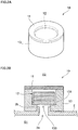
- FIGS. 2A and 2B are diagrams for explaining a configuration of the ventilation and humidity-conditioning unit 10 according to the present embodiment.
- FIG. 2A is a perspective view of the ventilation and humidity-conditioning unit 10 as viewed from obliquely above.
- FIG. 2B is a cross-sectional view of the ventilation and humidity-conditioning unit 10 when mounted to the opening 2a (protrusion 2b) of the vehicle lamp 1 (see FIG. 1 ), taken along a ventilation direction of the ventilation and humidity-conditioning unit 10.
- the ventilation and humidity-conditioning unit 10 of the present embodiment includes a ventilation filter 11 as an example of the ventilation member that provides ventilation between the internal space S1 and the external space S2 and prevents a sold and a liquid from entering the internal space S1.
- the ventilation and humidity-conditioning unit 10 further includes a humidity-conditioning member 12 that controls the humidity of the internal space S1 by absorbing or releasing water vapor.
- the ventilation and humidity-conditioning unit 10 further includes a holding member 13 as an example of the structure that holds the ventilation filter 11 and the humidity-conditioning member 12 and is fitted to the opening 2a (protrusion 2b) of the case 2.
- the ventilation filter 11 is a filter that prevents a liquid such as water and a solid such as dust from entering the internal space S1 and allows a gas such as air and water vapor to pass through the ventilation filter 11.
- the ventilation filter 11 may be formed of a porous film having plural holes manufactured by a stretching method, an extraction method or the like.
- the porous film used as the ventilation filter 11 include a polytetrafluoroethylene (PTFE) porous film.
- PTFE porous film is preferable in that it can maintain a ventilation property even with a small area and is highly capable of preventing water and dust from passing through the film.
- an average hole diameter of the holes formed in the porous film is typically in the range from not less than 0.01 ⁇ m to not more than 100 ⁇ m, preferably in the range from not less than 0.1 ⁇ m to not more than 50 ⁇ m, and more preferably in the range from not less than 0.5 ⁇ m to not more than 10 ⁇ m.
- the average hole diameter of the porous film can be measured by a mercury penetration method, for example.
- the average hole diameter of the porous film used as the ventilation filter 11 is less than 0.01 ⁇ m, a gas hardly passes through the ventilation filter 11. In this case, for example, when a temperature of the internal space S1 becomes high for reasons such as heat generation of the LED 4 and causes the air inside the internal space S1 to expand, it becomes difficult to quickly discharge the air from the internal space S1 to the external space S2.
- the average hole diameter of the porous film used as the ventilation filter 11 is more than 100 ⁇ m, dust and the like easily pass through the ventilation filter 11. In this case, dust and the like may easily attach to the humidity-conditioning member 12 and may easily enter the internal space S1.
- the surface (of a side facing the external space S2 in particular) of the ventilation filter 11 is preferably applied with a liquid-repellent treatment such as a water-repellent treatment and an oil-repellent treatment.
- a liquid-repellent treatment such as a water-repellent treatment and an oil-repellent treatment.
- a liquid-repellent treatment to the ventilation filter 11 may be performed by applying, to the surface of the ventilation filter 11, a liquid-repellent agent composed of a compound having a hydrocarbon group (perfluoroalkyl group) saturated with fluorine in a side chain and having a main chain of acrylic, methacrylic, silicone or other nature.
- the method for applying a liquid-repellent agent to the surface of the ventilation filter 11 is not particularly limited; for example, gravure coating, spray coating, kiss coating or dipping may be used.
- the humidity-conditioning member 12 of the present embodiment is made of a moisture absorbing and releasing material that has a property of absorbing water vapor under an environment where a surrounding relative humidity is high and releasing water vapor under an environment where a surrounding relative humidity is low (hereinafter this property may be simply referred to as a moisture absorbing and releasing property).
- the humidity-conditioning member 12 allows a gas such as unabsorbed water vapor and air to flow therethrough.
- the relative humidity at which the humidity-conditioning member 12 absorbs water vapor and the relative humidity at which the humidity-conditioning member 12 releases water vapor vary depending on a surrounding temperature, a kind of the humidity-conditioning member 12, an amount of water vapor adsorbed by the humidity-conditioning member 12 and the like.
- the environment where the humidity-conditioning member 12 absorbs water vapor corresponds to the "environment where a surrounding relative humidity is high”
- the environment where the humidity-conditioning member 12 releases water vapor corresponds to the "environment where a surrounding relative humidity is low”.
- Materials for the humidity-conditioning member 12 of the present embodiment are largely classified into inorganic moisture absorbing and releasing materials and organic moisture absorbing and releasing materials. Any of these two kinds of materials may be used as long as it ensures the moisture absorbing and releasing property of the humidity-conditioning member 12, and these two kinds of materials may be combined.
- inorganic moisture absorbing and releasing materials used as the humidity-conditioning member 12 include silica gel, zeolite, clay-based materials, quicklime, calcium chloride and magnesium chloride. Any of these materials may be used alone or combined with any other of these materials.
- Examples of organic moisture absorbing and releasing materials used as the humidity-conditioning member 12 include resin, fiber, woven fabric and nonwoven fabric subjected to a moisture absorbing and releasing treatment. More specifically, examples of organic moisture absorbing and releasing materials used as the humidity-conditioning member 12 include: crosslinked acrylate-based fiber, woven fabric and nonwoven fabric; fiber, woven fabric and nonwoven fabric obtained by hydrolyzing a surface of acrylic fiber in a post process; fiber, woven fabric and nonwoven fabric introduced by graft-polymerizing fiber such as polyolefin and polyester with a hydrophilic group such as a carboxyl group, a sulfonate group, a quaternary ammonium group and a salt thereof; and strong/weak acidic or strong/weak basic ion exchange resin, fiber, woven fabric and nonwoven fabric. Any of these materials may be used alone or combined with any other of these materials.
- sheet-like fabric, nonwoven fabric and the like is preferably used in terms of allowing for easier mounting to the holding member 13 and easier control of the moisture absorbing and releasing property of the ventilation and humidity-conditioning unit 10 and in terms of allowing the ventilation and humidity-conditioning unit 10 to be smaller and lighter.
- a moisture absorbing and releasing material having a heat resistance is preferably used as the humidity-conditioning member 12 because the ventilation and humidity-conditioning unit 10 may be placed under a high temperature environment for a long time when the ventilation and humidity-conditioning unit 10 is used for the vehicle lamp 1.
- the humidity-conditioning member 12 used in the present embodiment preferably has a maximum moisture absorption rate of 60% or more.
- the weight and volume of the humidity-conditioning member 12 provided to the ventilation and humidity-conditioning unit 10 can be smaller, preventing an increase in size of the ventilation and humidity-conditioning unit 10. Also, with a higher maximum moisture absorption rate of the humidity-conditioning member 12, the humidity of the internal space S1 of the vehicle lamp 1 can be more quickly reduced, preventing dew condensation and fogging on the cover lens 3 of the vehicle lamp 1.
- the maximum moisture absorption rate of the humidity-conditioning member 12 varies depending on the kind of the moisture absorbing and releasing material used as the humidity-conditioning member 12. Also, when an organic moisture absorbing and releasing material is used as the humidity-conditioning member 12, the maximum moisture absorption rate of the humidity-conditioning member 12 varies depending on the kind of moisture absorbing and releasing treatment applied to fiber, woven fabric or nonwoven fabric and the amount of treatment.
- the humidity-conditioning member 12 used for the vehicle lamp 1 of the present embodiment preferably has the weight Wa (g) in a dried state that satisfies the relationship of the following formula (1): Wa ⁇ V / A / 416 (where V: Volume (cm 3 ) of the vehicle lamp 1; A: maximum moisture absorption rate (%) of the humidity-conditioning member 12)
- the humidity of the internal space S1 can be lowered, preventing dew condensation and fogging on the cover lens 3 of the vehicle lamp 1.
- FIGS. 2A and 2B show a case where a sheet-like nonwoven fabric subjected to a moisture absorbing and releasing treatment is used as the humidity-conditioning member 12. More specifically, in the ventilation and humidity-conditioning unit 10 shown in FIGS. 2A and 2B , three stacked sheets of nonwoven fabric cut into a disk shape are used as the humidity-conditioning member 12. The sheets of the humidity-conditioning member 12 of the present embodiment are not adhered each another, and the humidity-conditioning member 12 is not adhered to the ventilation filter 11 and the holding member 13 either. Details of the humidity-conditioning member 12 will be described later.
- the holding member 13 has a substantially cylindrical shape as a whole.
- the holding member 13 includes therein a columnar ventilation hole 130 through which a gas passes.
- the ventilation hole 130 extends in a vertical direction from the internal space S1 side toward the external space S2 side.
- a circular protrusion 131 protruding inwardly to the ventilation hole 130 is formed.
- the holding member 13 of the present embodiment is made of thermoplastic elastomer or thermoplastic resin, for example.
- the ventilation filter 11 is attached to the holding member 13 such that the ventilation filter 11 closes an end portion of the ventilation hole 130 on the external space S2 side.
- the method for attaching the ventilation filter 11 to the holding member 13 is not particularly limited, and examples of the method include heat welding, ultrasonic welding and adhesion using a glue or an adhesive.
- the humidity-conditioning member 12 is placed on the protrusion 131 of the holding member 13 from the external space S2 side.
- the humidity-conditioning member 12 is thereby supported by the holding member 13.
- the humidity-conditioning member 12 is in contact with the holding member 13, the humidity-conditioning member 12 is not adhered to the holding member 13 and the ventilation filter 11.
- the state where the humidity-conditioning member 12 is adhered refers to the state where the humidity-conditioning member 12 is unable to perform its moisture absorbing and releasing function for reasons such as adhesion of a glue or an adhesive to the surface of the humidity-conditioning member 12 and denaturation of the surface of the humidity-conditioning member 12 due to melting or fusion.
- the humidity-conditioning member 12 is arranged midway in the ventilation path in the ventilation hole 130 extending from the internal space S1 side toward the external space S2 side, and the ventilation filter 11 is provided closer to the external space S2 than the humidity-conditioning member 12. This prevents the humidity-conditioning member 12 from exposing to the external space S2. As a result, liquid water, dust and the like are prevented from attaching to the humidity-conditioning member 12, and this prevents deterioration in the moisture absorbing and releasing property of the humidity-conditioning member 12.
- the ventilation and humidity-conditioning unit 10 of the present embodiment is mounted on the vehicle lamp 1 (see FIG. 1 ) with the holding member 13 being fitted to the opening 2a (the protrusion 2b) of the case 2. Specifically, the holding member 13 allows the protrusion 2b of the vehicle lamp 1 to be inserted into the end portion of the ventilation hole 130 on the internal space S1 side, and thereby the ventilation and humidity-conditioning unit 10 of the present embodiment is mounted on the vehicle lamp 1.
- the ventilation filter 11 and the humidity-conditioning member 12 is mounted on the vehicle lamp 1 with an easy operation of inserting the protrusion 2b into the ventilation hole 130 of the holding member 13.
- the ventilation filter 11 and the humidity-conditioning member 12 is easily mounted on the vehicle lamp 1 as compared with the case where the ventilation filter 11 and the humidity-conditioning member 12 is separately provided to the housing 2.
- the ventilation and humidity-conditioning unit 10 of the present embodiment is mounted on the vehicle lamp 1 from the external space S2 side of the vehicle lamp 1. This allows to easily remove the ventilation and humidity-conditioning unit 10 from the vehicle lamp 1 when, for example, the ventilation filter 11 or the humidity-conditioning member 12 is replaced.
- the method for mounting the ventilation and humidity-conditioning unit 10 on the vehicle lamp 1 is not particularly limited, and examples of adoptable methods include a method of threading the protrusion 2b and the holding member 13 to screw the holding member 13 into the protrusion 2b and a method of press-fitting the protrusion 2b into the ventilation hole 130 of the holding member 13.
- the ventilation and humidity-conditioning unit 10 mounted on the vehicle lamp 1 (see FIG. 1 ), the internal space S1 of the vehicle lamp 1 and the inside of the ventilation hole 130 in the holding member 13 of the ventilation and humidity-conditioning unit 10 form a continuous space.
- the humidity-conditioning member 12 is located above the internal space S1 in the vertical direction, and the ventilation filter 11 is located above the humidity-conditioning member 12 in the vertical direction.
- a conventional vehicle lamp 1 such as a head lamp suffers from a problem of dew condensation and fogging (a phenomenon in which the cover lens 3 becomes clouded by fine water droplets attached thereto) on the cover lens 3 that occur due to an increase in temperature of the internal space S1.
- the most effective way to prevent an increase in temperature of the internal space S1 of the vehicle lamp 1 is to seal the internal space S1 of the vehicle lamp 1 by the case 2 and the cover lens 3.
- plastics and the like composing the case 2 and the cover lens 3 have hygroscopicity, it is difficult to completely prevent water from entering the internal space S1.
- air inside the internal space S1 may expand to rapidly increase the pressure of the internal space S1 or air inside the internal space S1 may shrink to rapidly decrease the pressure of the internal space S1. This may cause breakage of the case 2 or the cover lens 3.
- the vehicle lamp 1 is preferably provided with a ventilation means to allow for ventilation between the internal space S1 and the external space S2.
- the ventilation means is provided to the vehicle lamp 1, when the humidity of the outside of the vehicle lamp 1 is high, high-humidity air containing water vapor may enter the internal space S1 through the ventilation means. Then, when the humidity of the internal space 1 increases and the temperature of the internal space 1 drops to or below a dew point, dew condensation or fogging occur on the cover lens 3.
- the ventilation and humidity-conditioning unit 10 not only provides ventilation between the internal space S1 and the external space S2 to eliminate the difference in pressure but also controls the humidity (performs humidity-conditioning) of the internal space S1 by adsorbing water vapor entering the internal space S1 through ventilation.
- the pressure of the internal space S1 may become lower than the pressure of the external space S2 for reasons such as a decrease in temperature of the internal space S1.
- a gas flows into the ventilation hole 130 from the external space S2 through the ventilation filter 11.
- this flow of the gas into the ventilation hole 130 from the external space S2 eliminates the difference in pressure between the internal space S1 and the external space S2.
- the ventilation filter 11 is composed of a filter that does not allow a liquid such as water and a solid such as dust to pass through the ventilation filter 11. Accordingly, even when the ventilation and humidity-conditioning unit 10 allows a gas to flow into the ventilation hole 130 from the external space S2, a liquid and a solid are prevented from entering the ventilation hole 130. This prevents dust and the like from attaching to the humidity-conditioning member 12, for example.
- the ventilation hole 130 is provided with the humidity-conditioning member 12.
- the humidity-conditioning member 12 has a property of absorbing water vapor under an environment where the relative humidity is high. Accordingly, when water vapor flows into the ventilation hole 130 from the external space S2 through the ventilation filter 11, the water vapor is adsorbed by the humidity-conditioning member 12. As a result, a gas with a reduced humidity, which is due to the water vapor being adsorbed by the humidity-conditioning member 12, flows into the internal space S1 from the ventilation hole 130. This prevents an increase in humidity of the internal space S1, as compared to the case where water vapor is not adsorbed by the humidity-conditioning member 12.
- the humidity-conditioning member 12 may not fully adsorb water vapor and may let some of the water vapor enter the internal space S1, and the humidity of the internal space S1 may increase as a result.
- the water vapor flowing into the internal space S1 contacts the humidity-conditioning member 12 through the ventilation hole 130 and is adsorbed by the humidity-conditioning member 12. This decreases the humidity of the internal space S1.
- the ventilation and humidity-conditioning unit 10 prevents water vapor from entering the internal space S1 and, when the humidity of the internal space S1 has increased, the ventilation and humidity-conditioning unit 10 decreases the humidity of the internal space S1. This prevents water vapor from attaching to the cover lens 3 to become water droplets, and thereby prevents dew condensation and fogging on the cover lens 3.
- the humidity-conditioning member 12 has a property of releasing adsorbed water vapor under an environment where the relative humidity is low. Accordingly, for example when the humidity of the external space S2 has decreased, the humidity-conditioning member 12 releases water vapor to restore its ability to adsorb water vapor.
- the ventilation filter 11 is located above the humidity-conditioning member 12 in the vertical direction. This allows water vapor released from the humidity-conditioning member 12 to rise upward in the vertical direction and pass through the ventilation filter 11 to be released to the external space S2.
- the humidity-conditioning member 12 is located above the internal space S1 of the vehicle lamp 1 in the vertical direction. This prevents water vapor released from the humidity-conditioning member 12 from moving to the internal space S1, and thereby prevents an increase in humidity of the internal space S1 due to water vapor released from the humidity-conditioning member 12.
- the humidity-conditioning member 12 is not adhered to the ventilation filter 11 and the holding member 13. This increases a surface area of the humidity-conditioning member 12 contacting a gas moving in the ventilation hole 130 as compared to, for example, the case where the humidity-conditioning member 12 is adhered to the ventilation filter 11 or the holding member 13.
- the ventilation and humidity-conditioning unit 10 of the present embodiment increases the ability of the humidity-conditioning member 12 to adsorb water vapor as compared to the case where the humidity-conditioning member 12 is adhered to the ventilation filter 11 or the holding member 13, thereby preventing an increase in humidity of the internal space S1. Also, when the humidity of the external space S1 has decreased, the humidity-conditioning member 12 more easily releases water vapor and quickly restores its ability to adsorb water vapor.
- the ventilation filter 11 for providing ventilation between the internal space S1 and the external space S2 and the humidity-conditioning member 12 for performing humidity-conditioning of the internal space S1 are integrated by the holding member 13 in the ventilation and humidity-conditioning unit 10. This simplifies the configuration of the vehicle lamp 1 as compared to, for example, the case where a member for providing ventilation between the internal space S1 and the external space S2 and a member for performing humidity-conditioning of the internal space S1 are separately provided in the vehicle lamp 1.
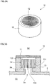
- FIGS. 3A and 3B are diagrams for illustrating another configuration example of the ventilation and humidity-conditioning unit 10.
- FIG. 3A is a perspective view of the ventilation and humidity-conditioning unit 10 as viewed from obliquely above. Note that the ventilation filter 11 is omitted in FIG. 3A.
- FIG. 3B is a cross-sectional view of the ventilation and humidity-conditioning unit 10 when fitted to the opening 2a (protrusion 2b) of the vehicle lamp 1 (see FIG. 1 ), taken along the ventilation direction of the ventilation and humidity-conditioning unit 10.
- the similar components to those of the ventilation and humidity-conditioning unit 10 shown in FIGS. 2A and 2B are denoted by the same reference numerals and detailed description thereof is omitted.
- a sheet-like moisture absorbing and releasing material is used as the humidity-conditioning member 12.
- the sheet-like moisture absorbing and releasing material is wound such that its cross-sectional shape cut in a plane perpendicular to the ventilation direction forms a spiral shape.
- woven fabric or nonwoven fabric as described above may be used as the sheet-like moisture absorbing and releasing material.
- the humidity-conditioning member 12 made of the sheet-like moisture absorbing and releasing material wound to have the spiral cross-section, plural gaps 120 are formed in the humidity-conditioning member 12 along the ventilation direction of the ventilation and humidity-conditioning unit 10, as shown in FIG. 3B .
- the present embodiment provides the ventilation and humidity-conditioning unit 10 that integrates the function of providing ventilation between the internal space S1 and the external space S2 and the function of performing humidity-conditioning of the internal space S1.
- the ventilation and humidity-conditioning unit 10 of the present embodiment when mounted on an apparatus such as the vehicle lamp 1, the ventilation and humidity-conditioning unit 10 prevents breakage of the case 2 or the cover lens 3 due to a difference in pressure between the internal space S1 and the external space S2, and prevents fogging and dew condensation on the cover lens 3.
- the ventilation filter 11 is provided on the external space S2 side with respect to the humidity-conditioning member 12
- another ventilation filter may be further provided to the internal space S1 side with respect to the humidity-conditioning member 12.
- the ventilation filters 11 may be provided on both of the internal space S1 side and the external space S2 side with respect to the humidity-conditioning member 12 on the ventilation path connecting the internal space S1 and the external space S2.
- the apparatuses to which the present invention is applicable are not limited to the vehicle lamp 1. That is, the present invention is applicable to any other apparatuses than the vehicle lamp 1 that include electronic components inside the case 2 and are prone to encounter problems of dew condensation and fogging on the cover lens 3 and an increase in humidity of the internal space S1, such as a car-mounted camera, a surveillance camera, a digital camera and an ECU (engine control unit).
- the humidity (relative humidity) inside the housing was measured while varying the weight of the humidity-conditioning member 12 of the ventilation and humidity-conditioning unit 10.
- the housing one including a closed-end container with a diameter of 100 mm and a height of 65 mm and a disk-like lid portion closing a circular opening of the container and having a volume of 500 cm 3 was used.
- the lid portion of the housing was provided with an opening 2a with a diameter of 5 mm, to which the ventilation and humidity-conditioning unit 10 having the shape shown in FIGS. 2A and 2B was fitted.
- a humidity sensor measuring the humidity inside the housing (the internal space S1) was installed on the container.
- the ventilation film 11 of the ventilation and humidity-conditioning unit 10 a film formed by thermally laminating a PTFE porous film with a thickness of 80 ⁇ m and nonwoven fabric made from a polyethylene and polyester mixture with a basis weight of 30 g/m 2 was used.
- nonwoven fabric with a basis weight of 130 g/m 2 and having a moisture absorbing and releasing property was used as the humidity-conditioning member 12 of the ventilation and humidity-conditioning unit 10.
- the maximum moisture absorption rate of this humidity-conditioning member 12 was 120%.
- the weight of the humidity-conditioning member 12 was varied between 0 g (the ventilation filter 11 alone without the humidity-conditioning member 12), 0.005 g, 0.010 g, 0.020 g and 0.040 g.
- the container and the lid portion of the housing mounted with the ventilation and humidity-conditioning unit 10 was placed at a temperature of 80C° and a relative humidity of 5% or less for 12 hours with the lid portion opened from the container, in such a manner that the ventilation filter 11 of the ventilation and humidity-conditioning unit 10 fitted to the opening 2a of the lid portion faced upward in the vertical direction. Subsequently, the container and the lid portion were placed at a temperature of 23C° and a relative humidity of 50% for 12 hours to make the internal environment constant. Thereafter, the lid portion was closed and a relative humidity (H1) of the internal space S1 was measured.
- H1 relative humidity
- the housing with the lid portion closed was placed in a thermohygrostat bath at a temperature of 23C° and a relative humidity of 95% in such a manner that the ventilation filter 11 of the ventilation and humidity-conditioning unit 10 faced upward in the vertical direction, and a relative humidity (H2) of the internal space S1 after two hours was measured.
- thermohygrostat bath was changed to 0%, and a relative humidity (H3) of the internal space S1 after two hours (four hours after the housing was placed in the thermohygrostat bath) was measured.
- FIG. 4 illustrates an amount of change in the humidity of the internal space S1 at different weights of the humidity-conditioning member 12 in Experiment Example 1.
- “Amount of change after 2hrs (%)” indicates an amount of change in the relative humidity (%) of the internal space S1 after two hours from when the housing was placed in the thermohygrostat bath (H2 - HI)
- “Amount of change after 4hrs (%)” indicates an amount of change in the relative humidity (%) of the internal space S1 after four hours (H3 - HI).
- the ventilation and humidity-conditioning unit 10 has the humidity-conditioning member 12 in addition to the ventilation filter 11, the humidity of the internal space S1 is decreased as compared to the case where the ventilation and humidity-conditioning unit 10 does not have the humidity-conditioning member 12 (the case where the ventilation and humidity-conditioning unit 10 only has the ventilation filter 11).
- the ventilation and humidity-conditioning unit 10 with the humidity-conditioning member 12 more effectively prevents water vapor from entering the internal space S1 than the ventilation and humidity-conditioning unit 10 without the humidity-conditioning member 12.
- the weight of the humidity-conditioning member 12 satisfies the above formula (1) (the weight of the humidity-conditioning member 12 is 0.010 g, 0.020 g or 0.040 g), the effect of decreasing the humidity of the internal space S1 becomes more pronounced than in the case where the humidity-conditioning member 12 does not satisfy the formula (1) (the weight of the humidity-conditioning member 12 is 0.005 g). More specifically, even when the housing is placed in the thermohygrostat bath at a temperature of 23C° and a relative humidity of 95%, the humidity-conditioning member 12 with the weight satisfying the above formula (1) can make the humidity of the internal space S1 lower than that before placement in the thermohygrostat bath.
- FIG. 5 illustrates an amount of change in the humidity of the internal space S1 at different weights of the humidity-conditioning member 12 in Experiment Example 2.
- the humidity-conditioning member 12 having the maximum moisture absorption rate of 60% too, when the weight of the humidity-conditioning member 12 satisfies the above formula (1) (the weight of the humidity-conditioning member 12 is 0.020 g or 0.040 g), the effect of decreasing the humidity of the internal space S1 becomes more pronounced than in the case where the humidity-conditioning member 12 does not satisfy the formula (1) (the weight of the humidity-conditioning member 12 is 0.005 g or 0.010 g).
- the humidity-conditioning member 12 with the weight satisfying the above formula (1) can make the humidity of the internal space S1 lower than that before placement in the thermohygrostat bath.
- Experiment Example 1 Comparing the results of Experiment Example 1 shown in FIG. 4 and Experiment Example 2 shown in FIG. 5 , it was found that Experiment Example 1, in which the humidity-conditioning member 12 with a higher maximum moisture absorption rate was used, more effectively produces the effect of decreasing the humidity of the internal space S1 than Experiment Example 2. In other words, it was found that, when the weight of the humidity-conditioning member 12 is equal, the humidity-conditioning member 12 with a higher maximum moisture absorption rate more effectively produces the effect of decreasing the humidity of the internal space S1.
- FIG. 6 illustrates an amount of change in the humidity of the internal space S1 at different weights of the humidity-conditioning member 12 in Experiment Example 7.
- Experiment Example 1 Comparing the results of Experiment Example 1 shown in FIG. 4 and Experiment Example 3 shown in FIG. 6 , it was found that Experiment Example 1, in which the humidity-conditioning member 12 was not adhered to the ventilation filter 11, more effectively produces the effect of decreasing the humidity of the internal space S1 than Experiment Example 3, in which the humidity-conditioning member 12 was adhered to the ventilation filter 11. In other words, it was found that adhering the humidity-conditioning member 12 to the ventilation filter 11 hinders the moisture absorbing function or the moisture releasing function of the humidity-conditioning member 12 as compared to the case where the humidity-conditioning member 12 is not adhered to the ventilation filter 11.
- the humidity of the internal space S1 of the housing was measured.
- the humidity of the internal space S1 of the housing was measured under the same conditions as Experiment Example 1 except that the housing was placed in the thermohygrostat bath in the state where the housing was vertically reversed from the orientation in Experiment Example 1.
- FIG. 7 illustrates an amount of change in the humidity of the internal space S1 at different weights of the humidity-conditioning member 12 in Experiment Example 4.
- the ventilation and humidity-conditioning unit 10 having the humidity-conditioning member 12 can decrease the humidity of the internal space S1 as compared to the case where the ventilation and humidity-conditioning unit 10 does not have the humidity-conditioning member 12.
Landscapes
- Engineering & Computer Science (AREA)
- Chemical & Material Sciences (AREA)
- General Engineering & Computer Science (AREA)
- Chemical Kinetics & Catalysis (AREA)
- General Chemical & Material Sciences (AREA)
- Oil, Petroleum & Natural Gas (AREA)
- Analytical Chemistry (AREA)
- Microelectronics & Electronic Packaging (AREA)
- Non-Portable Lighting Devices Or Systems Thereof (AREA)
- Arrangement Of Elements, Cooling, Sealing, Or The Like Of Lighting Devices (AREA)
- Casings For Electric Apparatus (AREA)
- Physics & Mathematics (AREA)
- Thermal Sciences (AREA)
- Mechanical Engineering (AREA)
- Drying Of Gases (AREA)
Abstract
Description
- The present invention relates to a ventilation and humidity-conditioning unit and an apparatus.
- Conventionally, some lighting apparatuses such as a vehicle lamp or optical apparatuses such as a surveillance camera are provided with a ventilation member for providing ventilation to the housing, in order to prevent deformation or breakage of the housing due to difference in pressure between the inside and the outside of the housing. When the housing is provided with the ventilation member, water vapor and the like may enter the housing through the ventilation member, which may lead to problems such as dew condensation inside the housing and fogging of a lens.
- In view of the above,
Patent Document 1 discloses a technique of filling the inside of a housing with a moisture absorbent such as silica gel to prevent fogging of a lens of an automobile lamp. - Patent Document 1: Japanese Patent Application Laid-Open Publication No.
9-102204 - By the way, when the humidity-conditioning member is placed inside the housing of an apparatus such as a vehicle lamp to control the humidity of the housing, it is difficult to remove the humidity-conditioning member from the housing, and in many cases replacement and the like of the humidity-conditioning member is not readily performable. Also, when the humidity-conditioning member is placed inside the housing of an apparatus, a ventilation member for providing ventilation between the inside and the outside of the housing needs to be mounted on the apparatus separately from the humidity-conditioning member, and this is likely to complicate the mounting of the ventilation member and the humidity-conditioning member on the apparatus.
- An object of the present invention is to provide both of the ventilation function of providing ventilation between the inside and the outside of the housing and the function of controlling humidity of the housing by mounting on the housing.
- With this object in view, the present invention is a ventilation and humidity-conditioning unit (10) including: a structure (13) mounted on a housing (2, 3) including a space inside (S1) the housing (2, 3), the structure (13) including a ventilation hole (130) providing ventilation between an inside (S1) of the housing (2, 3) and an outside (S2) of the housing (2, 3); a humidity-conditioning member (12) provided midway in the ventilation hole (130) of the structure (13), the humidity-conditioning member (12) absorbing water vapor; and a ventilation member (11) provided to the structure (13), the ventilation member (11) being closer to the outside (S2) of the housing (2, 3) than the humidity-conditioning member (12) is, the ventilation member (11) being permeable to a gas, the ventilation member (11) preventing a liquid and a solid from entering the inside (S1) of the housing (2, 3).
- Here, the humidity-conditioning member (12) may absorb water vapor under an environment where a surrounding relative humidity is high and release water vapor under an environment where a surrounding relative humidity is low, and may control a humidity of the inside (S1) of the housing (2, 3).
- Further, the humidity-conditioning member (12) and the ventilation member (11) may not be adhered to each other.
- In another aspect, the present invention is an apparatus (1) including: a dehumidifying target (4); a housing (2, 3) accommodating the dehumidifying target (4); a structure (13) engaged with the housing (2, 3), the structure (13) including a ventilation hole (130) that provides ventilation between an inside (S1) of the housing (2, 3) and an outside (S2) of the housing (2, 3); a humidity-conditioning member (12) provided midway in the ventilation hole (130) of the structure (13), the humidity-conditioning member (12) absorbing water vapor; and a ventilation member (11) provided to the structure (13), the ventilation member (11) being closer to the outside (S2) of the housing (2, 3) than the humidity-conditioning member (12) is, the ventilation member (11) being permeable to a gas, the ventilation member (11) preventing a liquid and a solid from entering the inside (S1) of the housing (2, 3).
- Here, a weight Wa of the humidity-conditioning member (12) may satisfy the following formula (1)

- Further, the humidity-conditioning member (12) may absorb water vapor under an environment where a surrounding relative humidity is high and releases water vapor under an environment where a surrounding relative humidity is low, and the structure (13) may be engaged with the housing (2, 3) such that the ventilation member (11) is located above the humidity-conditioning member (12) in a vertical direction.
- Note that the above reference signs in this section are added as examples for explaining the present invention and the present invention is not limited by these reference signs.
- According to the present invention, it is possible to provide both of the ventilation function of providing ventilation between the inside and the outside of the housing and the function of controlling humidity of the housing by mounting on the housing.
-
-
FIG. 1 is a diagram illustrating an overall configuration of a vehicle lamp according to a present embodiment. -
FIGS. 2A and 2B are diagrams for explaining a configuration of a ventilation and humidity-conditioning unit according to the present embodiment. -
FIGS. 3A and 3B are diagrams for explaining another example of a configuration of the ventilation and humidity-conditioning unit. -
FIG. 4 is a diagram illustrating an amount of change in the humidity of an internal space at different weights of a humidity-conditioning member in Experiment Example 1. -
FIG. 5 is a diagram illustrating an amount of change in the humidity of the internal space at different weights of the humidity-conditioning member in Experiment Example 2. -
FIG. 6 is a diagram illustrating an amount of change in the humidity of the internal space at different weights of the humidity-conditioning member in Experiment Example 3. -
FIG. 7 is a diagram illustrating an amount of change in the humidity of the internal space at different weights of the humidity-conditioning member in Experiment Example 4. - Hereinafter, an embodiment of the present invention will be described in detail with reference to the attached drawings.
-
FIG. 1 is a diagram illustrating an overall configuration of avehicle lamp 1 according to the present embodiment. - The
vehicle lamp 1 according to the present embodiment is, for example, used as a head lamp, a rear lamp, a brake lamp, a fog lamp, a turn signal lamp, a running lamp, a parking lamp and the like of various kinds of vehicles represented by automobiles.FIG. 1 illustrates a head lamp as an example of these lamps.FIG. 1 is a cross-sectional view of thevehicle lamp 1 taken along a traveling direction of the vehicle. InFIG. 1 , the left side in the figure corresponds to a front side of the vehicle and the right side in the figure corresponds to a rear side of the vehicle. - The
vehicle lamp 1 shown inFIG. 1 includes acase 2 that accommodates and protects components such as an LED 4 (described later), and a cover lens 3 that is mounted on thecase 2 and allows the light from theLED 4 to be emitted to the outside of thevehicle lamp 1. In thevehicle lamp 1, an internal space S1 is formed by thecase 2 and the cover lens 3. The internal space S1 is separated from an external space S2 of thevehicle lamp 1. This increases water-proofness and dust-proofness of the components accommodated in thecase 2. In the present embodiment, thecase 2 and the cover lens 3 constitute a housing of thevehicle lamp 1. - Further, the
vehicle lamp 1 includes a ventilation and humidity-conditioning unit 10 that provides ventilation between the internal space S1 and the external space S2 and controls the humidity of the internal space S1. - The
case 2 includes an opening 2a opened from the internal space S1 toward the external space S2. Specifically, the opening 2a is formed at a position in an upper part of thecase 2 in a vertical direction and on the rear side of the vehicle. In the present embodiment, theopening 2a is formed by acylindrical protrusion 2b protruding from thecase 2 toward the external space S2. - In the
vehicle lamp 1 of the present embodiment, the opening 2a of thecase 2 is mounted with the ventilation and humidity-conditioning unit 10. - The
vehicle lamp 1 further includes the LED (light emitting diode) 4 that is an example of the dehumidifying target and emits light, and a supportingmember 5 that supports theLED 4 and dissipates heat generated in theLED 4. Thevehicle lamp 1 further includes aprojection lens 6 that projects the light emitted from theLED 4 forward, and areflection mirror 7 that reflects the light emitted from theLED 4 toward theprojection lens 6. - Then, the ventilation and humidity-
conditioning unit 10 of the present embodiment will be explained.FIGS. 2A and 2B are diagrams for explaining a configuration of the ventilation and humidity-conditioning unit 10 according to the present embodiment.FIG. 2A is a perspective view of the ventilation and humidity-conditioning unit 10 as viewed from obliquely above.FIG. 2B is a cross-sectional view of the ventilation and humidity-conditioning unit 10 when mounted to the opening 2a (protrusion 2b) of the vehicle lamp 1 (seeFIG. 1 ), taken along a ventilation direction of the ventilation and humidity-conditioning unit 10. - As shown in
FIGS. 2A and 2B , the ventilation and humidity-conditioning unit 10 of the present embodiment includes aventilation filter 11 as an example of the ventilation member that provides ventilation between the internal space S1 and the external space S2 and prevents a sold and a liquid from entering the internal space S1. The ventilation and humidity-conditioning unit 10 further includes a humidity-conditioning member 12 that controls the humidity of the internal space S1 by absorbing or releasing water vapor. The ventilation and humidity-conditioning unit 10 further includes aholding member 13 as an example of the structure that holds theventilation filter 11 and the humidity-conditioning member 12 and is fitted to the opening 2a (protrusion 2b) of thecase 2. - The
ventilation filter 11 is a filter that prevents a liquid such as water and a solid such as dust from entering the internal space S1 and allows a gas such as air and water vapor to pass through theventilation filter 11. For example, theventilation filter 11 may be formed of a porous film having plural holes manufactured by a stretching method, an extraction method or the like. Examples of the porous film used as theventilation filter 11 include a polytetrafluoroethylene (PTFE) porous film. The PTFE porous film is preferable in that it can maintain a ventilation property even with a small area and is highly capable of preventing water and dust from passing through the film. - When a porous film is used as the
ventilation filter 11 of the present embodiment, an average hole diameter of the holes formed in the porous film is typically in the range from not less than 0.01 µm to not more than 100 µm, preferably in the range from not less than 0.1 µm to not more than 50 µm, and more preferably in the range from not less than 0.5 µm to not more than 10 µm. The average hole diameter of the porous film can be measured by a mercury penetration method, for example. - If the average hole diameter of the porous film used as the
ventilation filter 11 is less than 0.01 µm, a gas hardly passes through theventilation filter 11. In this case, for example, when a temperature of the internal space S1 becomes high for reasons such as heat generation of theLED 4 and causes the air inside the internal space S1 to expand, it becomes difficult to quickly discharge the air from the internal space S1 to the external space S2. On the other hand, if the average hole diameter of the porous film used as theventilation filter 11 is more than 100 µm, dust and the like easily pass through theventilation filter 11. In this case, dust and the like may easily attach to the humidity-conditioning member 12 and may easily enter the internal space S1. - The surface (of a side facing the external space S2 in particular) of the
ventilation filter 11 is preferably applied with a liquid-repellent treatment such as a water-repellent treatment and an oil-repellent treatment. Applying a liquid-repellent treatment to theventilation filter 11 prevents dirt and the like from attaching to theventilation filter 11. As a result, this prevents clogging of theventilation filter 11, which in turn prevents deterioration in the ventilating property of the ventilation and humidity-conditioning unit 10. - For example, a liquid-repellent treatment to the
ventilation filter 11 may be performed by applying, to the surface of theventilation filter 11, a liquid-repellent agent composed of a compound having a hydrocarbon group (perfluoroalkyl group) saturated with fluorine in a side chain and having a main chain of acrylic, methacrylic, silicone or other nature. The method for applying a liquid-repellent agent to the surface of theventilation filter 11 is not particularly limited; for example, gravure coating, spray coating, kiss coating or dipping may be used. - The humidity-
conditioning member 12 of the present embodiment is made of a moisture absorbing and releasing material that has a property of absorbing water vapor under an environment where a surrounding relative humidity is high and releasing water vapor under an environment where a surrounding relative humidity is low (hereinafter this property may be simply referred to as a moisture absorbing and releasing property). Note that the humidity-conditioning member 12 allows a gas such as unabsorbed water vapor and air to flow therethrough. Here, the relative humidity at which the humidity-conditioning member 12 absorbs water vapor and the relative humidity at which the humidity-conditioning member 12 releases water vapor vary depending on a surrounding temperature, a kind of the humidity-conditioning member 12, an amount of water vapor adsorbed by the humidity-conditioning member 12 and the like. In the explanation of the present embodiment, the environment where the humidity-conditioning member 12 absorbs water vapor corresponds to the "environment where a surrounding relative humidity is high", and the environment where the humidity-conditioning member 12 releases water vapor corresponds to the "environment where a surrounding relative humidity is low". - Materials for the humidity-
conditioning member 12 of the present embodiment are largely classified into inorganic moisture absorbing and releasing materials and organic moisture absorbing and releasing materials. Any of these two kinds of materials may be used as long as it ensures the moisture absorbing and releasing property of the humidity-conditioning member 12, and these two kinds of materials may be combined. - Examples of inorganic moisture absorbing and releasing materials used as the humidity-
conditioning member 12 include silica gel, zeolite, clay-based materials, quicklime, calcium chloride and magnesium chloride. Any of these materials may be used alone or combined with any other of these materials. - Examples of organic moisture absorbing and releasing materials used as the humidity-
conditioning member 12 include resin, fiber, woven fabric and nonwoven fabric subjected to a moisture absorbing and releasing treatment. More specifically, examples of organic moisture absorbing and releasing materials used as the humidity-conditioning member 12 include: crosslinked acrylate-based fiber, woven fabric and nonwoven fabric; fiber, woven fabric and nonwoven fabric obtained by hydrolyzing a surface of acrylic fiber in a post process; fiber, woven fabric and nonwoven fabric introduced by graft-polymerizing fiber such as polyolefin and polyester with a hydrophilic group such as a carboxyl group, a sulfonate group, a quaternary ammonium group and a salt thereof; and strong/weak acidic or strong/weak basic ion exchange resin, fiber, woven fabric and nonwoven fabric. Any of these materials may be used alone or combined with any other of these materials. - Among these materials, sheet-like fabric, nonwoven fabric and the like is preferably used in terms of allowing for easier mounting to the holding
member 13 and easier control of the moisture absorbing and releasing property of the ventilation and humidity-conditioning unit 10 and in terms of allowing the ventilation and humidity-conditioning unit 10 to be smaller and lighter. Further, a moisture absorbing and releasing material having a heat resistance is preferably used as the humidity-conditioning member 12 because the ventilation and humidity-conditioning unit 10 may be placed under a high temperature environment for a long time when the ventilation and humidity-conditioning unit 10 is used for thevehicle lamp 1. - Further, the humidity-
conditioning member 12 used in the present embodiment preferably has a maximum moisture absorption rate of 60% or more. In the present embodiment, the maximum moisture absorption rate refers to a ratio of Wb to Wa where Wb is a saturated weight of water absorbed by the humidity-conditioning member 12 at the temperature of 23C° and the relative humidity of 95%, and Wa is a weight of the humidity-conditioning member 12 in a dried state (the maximum moisture absorption rate A = (Wb/Wa) x 100 (%)). - With a higher maximum moisture absorption rate of the humidity-
conditioning member 12, the weight and volume of the humidity-conditioning member 12 provided to the ventilation and humidity-conditioning unit 10 can be smaller, preventing an increase in size of the ventilation and humidity-conditioning unit 10. Also, with a higher maximum moisture absorption rate of the humidity-conditioning member 12, the humidity of the internal space S1 of thevehicle lamp 1 can be more quickly reduced, preventing dew condensation and fogging on the cover lens 3 of thevehicle lamp 1. - The maximum moisture absorption rate of the humidity-
conditioning member 12 varies depending on the kind of the moisture absorbing and releasing material used as the humidity-conditioning member 12. Also, when an organic moisture absorbing and releasing material is used as the humidity-conditioning member 12, the maximum moisture absorption rate of the humidity-conditioning member 12 varies depending on the kind of moisture absorbing and releasing treatment applied to fiber, woven fabric or nonwoven fabric and the amount of treatment. - Further, the humidity-
conditioning member 12 used for thevehicle lamp 1 of the present embodiment preferably has the weight Wa (g) in a dried state that satisfies the relationship of the following formula (1):
vehicle lamp 1; A: maximum moisture absorption rate (%) of the humidity-conditioning member 12) - With the weight Wa (g) of the humidity-
conditioning member 12 in a dried state satisfying the above formula (1), an increase in temperature of the internal space S1 of thevehicle lamp 1 is inhibited as compared with a case where the weight Wa (g) of the humidity-conditioning member 12 in a dried state does not satisfy the formula (1). Further, even when the humidity of the internal space S1 of thevehicle lamp 1 increases, the humidity of the internal space S1 is quickly reduced. - As a result, compared with a case where the weight Wa (g) of the humidity-
conditioning member 12 in a dried state does not satisfy the formula (1), with the weight Wa (g) of the humidity-conditioning member 12 in a dried state satisfying the above formula (1), the humidity of the internal space S1 can be lowered, preventing dew condensation and fogging on the cover lens 3 of thevehicle lamp 1. -
FIGS. 2A and 2B show a case where a sheet-like nonwoven fabric subjected to a moisture absorbing and releasing treatment is used as the humidity-conditioning member 12. More specifically, in the ventilation and humidity-conditioning unit 10 shown inFIGS. 2A and 2B , three stacked sheets of nonwoven fabric cut into a disk shape are used as the humidity-conditioning member 12. The sheets of the humidity-conditioning member 12 of the present embodiment are not adhered each another, and the humidity-conditioning member 12 is not adhered to theventilation filter 11 and the holdingmember 13 either. Details of the humidity-conditioning member 12 will be described later. - The holding
member 13 has a substantially cylindrical shape as a whole. The holdingmember 13 includes therein acolumnar ventilation hole 130 through which a gas passes. When the ventilation and humidity-conditioning unit 10 is mounted on thecase 2 of thevehicle lamp 1, theventilation hole 130 extends in a vertical direction from the internal space S1 side toward the external space S2 side. At an end portion of the holdingmember 13 on the internal space S1 side, acircular protrusion 131 protruding inwardly to theventilation hole 130 is formed. - The holding
member 13 of the present embodiment is made of thermoplastic elastomer or thermoplastic resin, for example. - In the ventilation and humidity-
conditioning unit 10 of the present embodiment, theventilation filter 11 is attached to the holdingmember 13 such that theventilation filter 11 closes an end portion of theventilation hole 130 on the external space S2 side. The method for attaching theventilation filter 11 to the holdingmember 13 is not particularly limited, and examples of the method include heat welding, ultrasonic welding and adhesion using a glue or an adhesive. - Further, in the ventilation and humidity-
conditioning unit 10 of the present embodiment, the humidity-conditioning member 12 is placed on theprotrusion 131 of the holdingmember 13 from the external space S2 side. The humidity-conditioning member 12 is thereby supported by the holdingmember 13. In the ventilation and humidity-conditioning unit 10 of the present embodiment, although the humidity-conditioning member 12 is in contact with the holdingmember 13, the humidity-conditioning member 12 is not adhered to the holdingmember 13 and theventilation filter 11. In the present embodiment, the state where the humidity-conditioning member 12 is adhered refers to the state where the humidity-conditioning member 12 is unable to perform its moisture absorbing and releasing function for reasons such as adhesion of a glue or an adhesive to the surface of the humidity-conditioning member 12 and denaturation of the surface of the humidity-conditioning member 12 due to melting or fusion. - As described above, in the ventilation and humidity-
conditioning unit 10 of the present embodiment, the humidity-conditioning member 12 is arranged midway in the ventilation path in theventilation hole 130 extending from the internal space S1 side toward the external space S2 side, and theventilation filter 11 is provided closer to the external space S2 than the humidity-conditioning member 12. This prevents the humidity-conditioning member 12 from exposing to the external space S2. As a result, liquid water, dust and the like are prevented from attaching to the humidity-conditioning member 12, and this prevents deterioration in the moisture absorbing and releasing property of the humidity-conditioning member 12. - The ventilation and humidity-
conditioning unit 10 of the present embodiment is mounted on the vehicle lamp 1 (seeFIG. 1 ) with the holdingmember 13 being fitted to theopening 2a (theprotrusion 2b) of thecase 2. Specifically, the holdingmember 13 allows theprotrusion 2b of thevehicle lamp 1 to be inserted into the end portion of theventilation hole 130 on the internal space S1 side, and thereby the ventilation and humidity-conditioning unit 10 of the present embodiment is mounted on thevehicle lamp 1. - In this way, in the present embodiment, the
ventilation filter 11 and the humidity-conditioning member 12 is mounted on thevehicle lamp 1 with an easy operation of inserting theprotrusion 2b into theventilation hole 130 of the holdingmember 13. In other words, in the present embodiment, theventilation filter 11 and the humidity-conditioning member 12 is easily mounted on thevehicle lamp 1 as compared with the case where theventilation filter 11 and the humidity-conditioning member 12 is separately provided to thehousing 2. - The ventilation and humidity-
conditioning unit 10 of the present embodiment is mounted on thevehicle lamp 1 from the external space S2 side of thevehicle lamp 1. This allows to easily remove the ventilation and humidity-conditioning unit 10 from thevehicle lamp 1 when, for example, theventilation filter 11 or the humidity-conditioning member 12 is replaced. - The method for mounting the ventilation and humidity-
conditioning unit 10 on thevehicle lamp 1 is not particularly limited, and examples of adoptable methods include a method of threading theprotrusion 2b and the holdingmember 13 to screw the holdingmember 13 into theprotrusion 2b and a method of press-fitting theprotrusion 2b into theventilation hole 130 of the holdingmember 13. - As shown in
FIG. 2B , with the ventilation and humidity-conditioning unit 10 mounted on the vehicle lamp 1 (seeFIG. 1 ), the internal space S1 of thevehicle lamp 1 and the inside of theventilation hole 130 in the holdingmember 13 of the ventilation and humidity-conditioning unit 10 form a continuous space. - Further, as shown in
FIG. 2B , in the state where the ventilation and humidity-conditioning unit 10 is mounted on thevehicle lamp 1, the humidity-conditioning member 12 is located above the internal space S1 in the vertical direction, and theventilation filter 11 is located above the humidity-conditioning member 12 in the vertical direction. - By the way, a
conventional vehicle lamp 1 such as a head lamp suffers from a problem of dew condensation and fogging (a phenomenon in which the cover lens 3 becomes clouded by fine water droplets attached thereto) on the cover lens 3 that occur due to an increase in temperature of the internal space S1. The most effective way to prevent an increase in temperature of the internal space S1 of thevehicle lamp 1 is to seal the internal space S1 of thevehicle lamp 1 by thecase 2 and the cover lens 3. However, since plastics and the like composing thecase 2 and the cover lens 3 have hygroscopicity, it is difficult to completely prevent water from entering the internal space S1. - Also, if the internal space S1 of the
vehicle lamp 1 is sealed by thecase 2 and the cover lens 3, air inside the internal space S1 may expand to rapidly increase the pressure of the internal space S1 or air inside the internal space S1 may shrink to rapidly decrease the pressure of the internal space S1. This may cause breakage of thecase 2 or the cover lens 3. - Accordingly, to prevent a rapid change in the pressure of the internal space S1, the
vehicle lamp 1 is preferably provided with a ventilation means to allow for ventilation between the internal space S1 and the external space S2. - Here, in a case where the ventilation means is provided to the
vehicle lamp 1, when the humidity of the outside of thevehicle lamp 1 is high, high-humidity air containing water vapor may enter the internal space S1 through the ventilation means. Then, when the humidity of theinternal space 1 increases and the temperature of theinternal space 1 drops to or below a dew point, dew condensation or fogging occur on the cover lens 3. - To prevent dew condensation and fogging on the cover lens 3, it is preferable to keep the humidity of the internal space S1 low by preventing water vapor from entering the internal space S1 and, when water vapor enters the internal space S1 to increase the humidity of the internal space S1, it is preferable to quickly decrease the humidity of the internal space S1.
- Accordingly, in the
vehicle lamp 1 of the present embodiment, the ventilation and humidity-conditioning unit 10 not only provides ventilation between the internal space S1 and the external space S2 to eliminate the difference in pressure but also controls the humidity (performs humidity-conditioning) of the internal space S1 by adsorbing water vapor entering the internal space S1 through ventilation. - Next, a ventilation operation and a humidity-conditioning operation performed by the ventilation and humidity-
conditioning unit 10 of the present embodiment will be explained. In thevehicle lamp 1 of the present embodiment, the pressure of the internal space S1 may become lower than the pressure of the external space S2 for reasons such as a decrease in temperature of the internal space S1. In this case, in the ventilation and humidity-conditioning unit 10, a gas flows into theventilation hole 130 from the external space S2 through theventilation filter 11. As described above, since theventilation hole 130 and the internal space S1 form a continuous space in the state where the ventilation and humidity-conditioning unit 10 is mounted on thevehicle lamp 1, this flow of the gas into theventilation hole 130 from the external space S2 eliminates the difference in pressure between the internal space S1 and the external space S2. - Further, as described above, the
ventilation filter 11 is composed of a filter that does not allow a liquid such as water and a solid such as dust to pass through theventilation filter 11. Accordingly, even when the ventilation and humidity-conditioning unit 10 allows a gas to flow into theventilation hole 130 from the external space S2, a liquid and a solid are prevented from entering theventilation hole 130. This prevents dust and the like from attaching to the humidity-conditioning member 12, for example. - Here, when the relative humidity of the external space S2 is higher than the relative humidity of the
ventilation hole 130 or the internal space S1, a high-humidity gas (water vapor) flows into theventilation hole 130 from the external space S2 through theventilation filter 11. - As described above, the
ventilation hole 130 is provided with the humidity-conditioning member 12. The humidity-conditioning member 12 has a property of absorbing water vapor under an environment where the relative humidity is high. Accordingly, when water vapor flows into theventilation hole 130 from the external space S2 through theventilation filter 11, the water vapor is adsorbed by the humidity-conditioning member 12. As a result, a gas with a reduced humidity, which is due to the water vapor being adsorbed by the humidity-conditioning member 12, flows into the internal space S1 from theventilation hole 130. This prevents an increase in humidity of the internal space S1, as compared to the case where water vapor is not adsorbed by the humidity-conditioning member 12. - Further, for example when the difference in pressure between the internal space S1 and the external space S2 is large and a gas flows from the external space S2 at a fast flow rate, the humidity-
conditioning member 12 may not fully adsorb water vapor and may let some of the water vapor enter the internal space S1, and the humidity of the internal space S1 may increase as a result. In this case, the water vapor flowing into the internal space S1 contacts the humidity-conditioning member 12 through theventilation hole 130 and is adsorbed by the humidity-conditioning member 12. This decreases the humidity of the internal space S1. - In this way, in the
vehicle lamp 1 of the present embodiment, the ventilation and humidity-conditioning unit 10 prevents water vapor from entering the internal space S1 and, when the humidity of the internal space S1 has increased, the ventilation and humidity-conditioning unit 10 decreases the humidity of the internal space S1. This prevents water vapor from attaching to the cover lens 3 to become water droplets, and thereby prevents dew condensation and fogging on the cover lens 3. - Further, as described above, the humidity-
conditioning member 12 has a property of releasing adsorbed water vapor under an environment where the relative humidity is low. Accordingly, for example when the humidity of the external space S2 has decreased, the humidity-conditioning member 12 releases water vapor to restore its ability to adsorb water vapor. - Here, since the density of water vapor is smaller than that of air, water vapor released from the humidity-
conditioning member 12 generally rises upward in the vertical direction. As described above, in the state where the ventilation and humidity-conditioning unit 10 of the present embodiment is mounted on thevehicle lamp 1, theventilation filter 11 is located above the humidity-conditioning member 12 in the vertical direction. This allows water vapor released from the humidity-conditioning member 12 to rise upward in the vertical direction and pass through theventilation filter 11 to be released to the external space S2. - Further, as described above, the humidity-
conditioning member 12 is located above the internal space S1 of thevehicle lamp 1 in the vertical direction. This prevents water vapor released from the humidity-conditioning member 12 from moving to the internal space S1, and thereby prevents an increase in humidity of the internal space S1 due to water vapor released from the humidity-conditioning member 12. - Further, as described above, in the ventilation and humidity-
conditioning unit 10 of the present embodiment, the humidity-conditioning member 12 is not adhered to theventilation filter 11 and the holdingmember 13. This increases a surface area of the humidity-conditioning member 12 contacting a gas moving in theventilation hole 130 as compared to, for example, the case where the humidity-conditioning member 12 is adhered to theventilation filter 11 or the holdingmember 13. - With this configuration, the ventilation and humidity-
conditioning unit 10 of the present embodiment increases the ability of the humidity-conditioning member 12 to adsorb water vapor as compared to the case where the humidity-conditioning member 12 is adhered to theventilation filter 11 or the holdingmember 13, thereby preventing an increase in humidity of the internal space S1. Also, when the humidity of the external space S1 has decreased, the humidity-conditioning member 12 more easily releases water vapor and quickly restores its ability to adsorb water vapor. - Further, in the present embodiment, the
ventilation filter 11 for providing ventilation between the internal space S1 and the external space S2 and the humidity-conditioning member 12 for performing humidity-conditioning of the internal space S1 are integrated by the holdingmember 13 in the ventilation and humidity-conditioning unit 10. This simplifies the configuration of thevehicle lamp 1 as compared to, for example, the case where a member for providing ventilation between the internal space S1 and the external space S2 and a member for performing humidity-conditioning of the internal space S1 are separately provided in thevehicle lamp 1. - Next, another configuration example of the ventilation and humidity-
conditioning unit 10 will be explained.FIGS. 3A and 3B are diagrams for illustrating another configuration example of the ventilation and humidity-conditioning unit 10.FIG. 3A is a perspective view of the ventilation and humidity-conditioning unit 10 as viewed from obliquely above. Note that theventilation filter 11 is omitted inFIG. 3A. FIG. 3B is a cross-sectional view of the ventilation and humidity-conditioning unit 10 when fitted to theopening 2a (protrusion 2b) of the vehicle lamp 1 (seeFIG. 1 ), taken along the ventilation direction of the ventilation and humidity-conditioning unit 10. Here, the similar components to those of the ventilation and humidity-conditioning unit 10 shown inFIGS. 2A and 2B are denoted by the same reference numerals and detailed description thereof is omitted. - In the ventilation and humidity-
conditioning unit 10 shown inFIGS. 3A and 3B , a sheet-like moisture absorbing and releasing material is used as the humidity-conditioning member 12. The sheet-like moisture absorbing and releasing material is wound such that its cross-sectional shape cut in a plane perpendicular to the ventilation direction forms a spiral shape. As the sheet-like moisture absorbing and releasing material, woven fabric or nonwoven fabric as described above may be used. - By use of the humidity-
conditioning member 12 made of the sheet-like moisture absorbing and releasing material wound to have the spiral cross-section,plural gaps 120 are formed in the humidity-conditioning member 12 along the ventilation direction of the ventilation and humidity-conditioning unit 10, as shown inFIG. 3B . - As a result, when the pressure of the internal space S1 becomes lower than the pressure of the external space S2, a gas flowing from the external space S2 through the
ventilation filter 11 passes thegaps 120 formed in the humidity-conditioning member 12 to move to the internal space S1. At this time, the gas moving through thegaps 120 contacts the surface of the humidity-conditioning member 12. Accordingly, water vapor contained in the gas is easily adsorbed by the humidity-conditioning member 12, and this allows to more effectively prevent an increase in humidity of the internal space S1 when a high-humidity gas flows from the external space S2. - As explained above, the present embodiment provides the ventilation and humidity-
conditioning unit 10 that integrates the function of providing ventilation between the internal space S1 and the external space S2 and the function of performing humidity-conditioning of the internal space S1. Thus, when the ventilation and humidity-conditioning unit 10 of the present embodiment is mounted on an apparatus such as thevehicle lamp 1, the ventilation and humidity-conditioning unit 10 prevents breakage of thecase 2 or the cover lens 3 due to a difference in pressure between the internal space S1 and the external space S2, and prevents fogging and dew condensation on the cover lens 3. - Although, in the ventilation and humidity-
conditioning unit 10 of the above embodiment, theventilation filter 11 is provided on the external space S2 side with respect to the humidity-conditioning member 12, another ventilation filter may be further provided to the internal space S1 side with respect to the humidity-conditioning member 12. In other words, in the ventilation and humidity-conditioning unit 10, the ventilation filters 11 may be provided on both of the internal space S1 side and the external space S2 side with respect to the humidity-conditioning member 12 on the ventilation path connecting the internal space S1 and the external space S2. - With this configuration, two
ventilation filters 11 are present on the ventilation path between the internal space S1 and the external space S2, and this allows to more effectively prevent a liquid and a solid from entering the internal space S1 when a gas flows into the internal space S1 from the external space S2. - Also, even with this configuration, water vapor flowing into the internal space S1 is adsorbed by the humidity-
conditioning member 12 by passing through theventilation filter 11 provided on the internal space S1 side. The humidity of the internal space S1 is thereby decreased as in the above embodiment. - Although the above embodiment uses the
vehicle lamp 1 including theLED 4 inside thecase 2 as an example of apparatuses for which the ventilation and humidity-conditioning unit 10 performs ventilation and humidity-conditioning (dehumidifying), the apparatuses to which the present invention is applicable are not limited to thevehicle lamp 1. That is, the present invention is applicable to any other apparatuses than thevehicle lamp 1 that include electronic components inside thecase 2 and are prone to encounter problems of dew condensation and fogging on the cover lens 3 and an increase in humidity of the internal space S1, such as a car-mounted camera, a surveillance camera, a digital camera and an ECU (engine control unit). - Then, the function of the ventilation and humidity-
conditioning unit 10 is explained in more detail using experiment examples. - Assuming a substantially columnar housing mounted with the ventilation and humidity-
conditioning unit 10 to be the housing of thevehicle lamp 1, the humidity (relative humidity) inside the housing (the internal space S1) was measured while varying the weight of the humidity-conditioning member 12 of the ventilation and humidity-conditioning unit 10. - As the housing, one including a closed-end container with a diameter of 100 mm and a height of 65 mm and a disk-like lid portion closing a circular opening of the container and having a volume of 500 cm3 was used. The lid portion of the housing was provided with an
opening 2a with a diameter of 5 mm, to which the ventilation and humidity-conditioning unit 10 having the shape shown inFIGS. 2A and 2B was fitted. A humidity sensor measuring the humidity inside the housing (the internal space S1) was installed on the container. - As the
ventilation film 11 of the ventilation and humidity-conditioning unit 10, a film formed by thermally laminating a PTFE porous film with a thickness of 80 µm and nonwoven fabric made from a polyethylene and polyester mixture with a basis weight of 30 g/m2 was used. - As the humidity-
conditioning member 12 of the ventilation and humidity-conditioning unit 10, nonwoven fabric with a basis weight of 130 g/m2 and having a moisture absorbing and releasing property was used. The maximum moisture absorption rate of this humidity-conditioning member 12 was 120%. The weight of the humidity-conditioning member 12 was varied between 0 g (theventilation filter 11 alone without the humidity-conditioning member 12), 0.005 g, 0.010 g, 0.020 g and 0.040 g. - The container and the lid portion of the housing mounted with the ventilation and humidity-
conditioning unit 10 was placed at a temperature of 80C° and a relative humidity of 5% or less for 12 hours with the lid portion opened from the container, in such a manner that theventilation filter 11 of the ventilation and humidity-conditioning unit 10 fitted to theopening 2a of the lid portion faced upward in the vertical direction. Subsequently, the container and the lid portion were placed at a temperature of 23C° and a relative humidity of 50% for 12 hours to make the internal environment constant. Thereafter, the lid portion was closed and a relative humidity (H1) of the internal space S1 was measured. - Then, the housing with the lid portion closed was placed in a thermohygrostat bath at a temperature of 23C° and a relative humidity of 95% in such a manner that the
ventilation filter 11 of the ventilation and humidity-conditioning unit 10 faced upward in the vertical direction, and a relative humidity (H2) of the internal space S1 after two hours was measured. - After that, the relative humidity of the thermohygrostat bath was changed to 0%, and a relative humidity (H3) of the internal space S1 after two hours (four hours after the housing was placed in the thermohygrostat bath) was measured.
-
FIG. 4 illustrates an amount of change in the humidity of the internal space S1 at different weights of the humidity-conditioning member 12 in Experiment Example 1. InFIG. 4 , "Amount of change after 2hrs (%)" indicates an amount of change in the relative humidity (%) of the internal space S1 after two hours from when the housing was placed in the thermohygrostat bath (H2 - HI), and "Amount of change after 4hrs (%)" indicates an amount of change in the relative humidity (%) of the internal space S1 after four hours (H3 - HI). - As shown in
FIG. 4 , it was found that when the ventilation and humidity-conditioning unit 10 has the humidity-conditioning member 12 in addition to theventilation filter 11, the humidity of the internal space S1 is decreased as compared to the case where the ventilation and humidity-conditioning unit 10 does not have the humidity-conditioning member 12 (the case where the ventilation and humidity-conditioning unit 10 only has the ventilation filter 11). In other words, it was found that the ventilation and humidity-conditioning unit 10 with the humidity-conditioning member 12 more effectively prevents water vapor from entering the internal space S1 than the ventilation and humidity-conditioning unit 10 without the humidity-conditioning member 12. - Also, as shown in
FIG. 4 , it was found that with a higher weight of the humidity-conditioning member 12 used in the ventilation and humidity-conditioning unit 10, the humidity of the internal space S1 becomes lower. - Further, it was found that when the weight of the humidity-
conditioning member 12 satisfies the above formula (1) (the weight of the humidity-conditioning member 12 is 0.010 g, 0.020 g or 0.040 g), the effect of decreasing the humidity of the internal space S1 becomes more pronounced than in the case where the humidity-conditioning member 12 does not satisfy the formula (1) (the weight of the humidity-conditioning member 12 is 0.005 g). More specifically, even when the housing is placed in the thermohygrostat bath at a temperature of 23C° and a relative humidity of 95%, the humidity-conditioning member 12 with the weight satisfying the above formula (1) can make the humidity of the internal space S1 lower than that before placement in the thermohygrostat bath. - Under the same conditions as Experiment Example 1 except that the humidity-
conditioning member 12 having the maximum moisture absorption rate of 60% was used, the humidity of the internal space S1 of the housing was measured. -
FIG. 5 illustrates an amount of change in the humidity of the internal space S1 at different weights of the humidity-conditioning member 12 in Experiment Example 2. - As shown in
FIG. 5 , it was found that with the humidity-conditioning member 12 having the maximum moisture absorption rate of 60% too, the humidity of the internal space S1 becomes lower than in the case where the ventilation and humidity-conditioning unit 10 does not have the humidity-conditioning member 12, similarly to Experiment Example 1. - Further, it was found that with the humidity-
conditioning member 12 having the maximum moisture absorption rate of 60% too, when the weight of the humidity-conditioning member 12 satisfies the above formula (1) (the weight of the humidity-conditioning member 12 is 0.020 g or 0.040 g), the effect of decreasing the humidity of the internal space S1 becomes more pronounced than in the case where the humidity-conditioning member 12 does not satisfy the formula (1) (the weight of the humidity-conditioning member 12 is 0.005 g or 0.010 g). More specifically, even when the housing is placed in the thermohygrostat bath at a temperature of 23C° and a relative humidity of 95%, the humidity-conditioning member 12 with the weight satisfying the above formula (1) can make the humidity of the internal space S1 lower than that before placement in the thermohygrostat bath. - Comparing the results of Experiment Example 1 shown in
FIG. 4 and Experiment Example 2 shown inFIG. 5 , it was found that Experiment Example 1, in which the humidity-conditioning member 12 with a higher maximum moisture absorption rate was used, more effectively produces the effect of decreasing the humidity of the internal space S1 than Experiment Example 2. In other words, it was found that, when the weight of the humidity-conditioning member 12 is equal, the humidity-conditioning member 12 with a higher maximum moisture absorption rate more effectively produces the effect of decreasing the humidity of the internal space S1. - Under the same conditions as Experiment Example 1 except that the humidity-
conditioning member 12 was adhered to theventilation filter 11 by thermal lamination, the humidity of the internal space S1 of the housing was measured. -
FIG. 6 illustrates an amount of change in the humidity of the internal space S1 at different weights of the humidity-conditioning member 12 in Experiment Example 7. - As shown in
FIG. 6 , it was found that with the humidity-conditioning member 12 adhered to theventilation filter 11 too, the humidity of the internal space S1 becomes lower than in the case where the ventilation and humidity-conditioning unit 10 does not have the humidity-conditioning member 12. - Comparing the results of Experiment Example 1 shown in
FIG. 4 and Experiment Example 3 shown inFIG. 6 , it was found that Experiment Example 1, in which the humidity-conditioning member 12 was not adhered to theventilation filter 11, more effectively produces the effect of decreasing the humidity of the internal space S1 than Experiment Example 3, in which the humidity-conditioning member 12 was adhered to theventilation filter 11. In other words, it was found that adhering the humidity-conditioning member 12 to theventilation filter 11 hinders the moisture absorbing function or the moisture releasing function of the humidity-conditioning member 12 as compared to the case where the humidity-conditioning member 12 is not adhered to theventilation filter 11. - Under the same conditions as Experiment Example 1 except that the housing was placed in the thermohygrostat bath in such a manner that the
ventilation filter 11 of the ventilation and humidity-conditioning unit 10 faced downward in the vertical direction, the humidity of the internal space S1 of the housing was measured. In other words, the humidity of the internal space S1 of the housing was measured under the same conditions as Experiment Example 1 except that the housing was placed in the thermohygrostat bath in the state where the housing was vertically reversed from the orientation in Experiment Example 1. -
FIG. 7 illustrates an amount of change in the humidity of the internal space S1 at different weights of the humidity-conditioning member 12 in Experiment Example 4. - As shown in
FIG. 7 , it was found that even when the housing is vertically reversed such that theventilation filter 11 faces downward in the vertical direction, the ventilation and humidity-conditioning unit 10 having the humidity-conditioning member 12 can decrease the humidity of the internal space S1 as compared to the case where the ventilation and humidity-conditioning unit 10 does not have the humidity-conditioning member 12. - Also, as shown in
FIG. 7 , it was found that, under the conditions where the housing is placed such that theventilation filter 11 faces downward in the vertical direction and the humidity-conditioning member 12 has the weight of 0.010 g or more, when the relative humidity of the thermohygrostat bath is changed to 0%, the humidity of the internal space S1 increases from the humidity before changing the relative humidity of the thermohygrostat bath. Assumedly this is because water vapor released from the humidity-conditioning member 12 moves to the internal space S1 located above the humidity-conditioning member 12 in the vertical direction. -
- 1
- Vehicle lamp
- 2
- Case
- 3
- Cover lens
- 10
- Ventilation and humidity-conditioning unit
- 11
- Ventilation filter
- 12
- Humidity-conditioning member
- 13
- Holding member
Claims (6)
- A ventilation and humidity-conditioning unit comprising:a structure mounted on a housing including a space inside the housing, the structure including a ventilation hole providing ventilation between an inside of the housing and an outside of the housing;a humidity-conditioning member provided midway in the ventilation hole of the structure, the humidity-conditioning member absorbing water vapor; anda ventilation member provided to the structure, the ventilation member being closer to the outside of the housing than the humidity-conditioning member is, the ventilation member being permeable to a gas, the ventilation member preventing a liquid and a solid from entering the inside of the housing.
- The ventilation and humidity-conditioning unit according to claim 1, wherein the humidity-conditioning member absorbs water vapor under an environment where a surrounding relative humidity is high and releases water vapor under an environment where a surrounding relative humidity is low, and controls a humidity of the inside of the housing.
- The ventilation and humidity-conditioning unit according to claim 1 or 2, wherein the humidity-conditioning member and the ventilation member are not adhered to each other.
- An apparatus comprising:a dehumidifying target;a housing accommodating the dehumidifying target;a structure engaged with the housing, the structure including a ventilation hole that provides ventilation between an inside of the housing and an outside of the housing;a humidity-conditioning member provided midway in the ventilation hole of the structure, the humidity-conditioning member absorbing water vapor; anda ventilation member provided to the structure, the ventilation member being closer to the outside of the housing than the humidity-conditioning member is, the ventilation member being permeable to a gas, the ventilation member preventing a liquid and a solid from entering the inside of the housing.
- The apparatus according to claim 4, wherein a weight Wa of the humidity-conditioning member satisfies the following formula (1)

- The apparatus according to claim 4 or 5, wherein the humidity-conditioning member absorbs water vapor under an environment where a surrounding relative humidity is high and releases water vapor under an environment where a surrounding relative humidity is low, and
the structure is engaged with the housing such that the ventilation member is located above the humidity-conditioning member in a vertical direction.
Applications Claiming Priority (2)
| Application Number | Priority Date | Filing Date | Title |
|---|---|---|---|
| JP2015246748A JP6823371B2 (en) | 2015-12-17 | 2015-12-17 | Ventilation and humidity control unit and equipment |
| PCT/JP2016/086885 WO2017104603A1 (en) | 2015-12-17 | 2016-12-12 | Ventilation and humidity-conditioning unit, and equipment |
Publications (2)
| Publication Number | Publication Date |
|---|---|
| EP3393219A1 true EP3393219A1 (en) | 2018-10-24 |
| EP3393219A4 EP3393219A4 (en) | 2019-06-19 |
Family
ID=59056682
Family Applications (1)
| Application Number | Title | Priority Date | Filing Date |
|---|---|---|---|
| EP16875580.9A Withdrawn EP3393219A4 (en) | 2015-12-17 | 2016-12-12 | Ventilation and humidity-conditioning unit, and equipment |
Country Status (5)
| Country | Link |
|---|---|
| US (1) | US10458640B2 (en) |
| EP (1) | EP3393219A4 (en) |
| JP (1) | JP6823371B2 (en) |
| CN (1) | CN108370648A (en) |
| WO (1) | WO2017104603A1 (en) |
Cited By (2)
| Publication number | Priority date | Publication date | Assignee | Title |
|---|---|---|---|---|
| WO2023135130A1 (en) * | 2022-01-17 | 2023-07-20 | Aml Systems | Device for dehumidifying a closed casing |
| US12364947B2 (en) | 2021-11-22 | 2025-07-22 | Raytheon Company | Aeration rod |
Families Citing this family (18)
| Publication number | Priority date | Publication date | Assignee | Title |
|---|---|---|---|---|
| US20190120456A1 (en) * | 2016-05-16 | 2019-04-25 | Mitsubishi Electric Corporation | Vehicle-mounted lamp fitting |
| KR102063948B1 (en) * | 2017-06-28 | 2020-01-09 | 경기대학교 산학협력단 | waterproof and moisture transmitting vent and vent module and LED lighting having the same |
| JP6590996B1 (en) * | 2018-06-01 | 2019-10-16 | 株式会社小糸製作所 | Vehicle lighting |
| WO2019230910A1 (en) | 2018-06-01 | 2019-12-05 | 株式会社小糸製作所 | Lamp for vehicles |
| EP3880343A4 (en) | 2018-11-14 | 2022-10-26 | Bimed Teknik Aletler Sanayi ve Ticaret Anonim Sirketi | Pressure balancing device |
| KR200491984Y1 (en) * | 2018-12-07 | 2020-07-13 | 에스엘 주식회사 | Apparatus of dehumidifying in the lamp for vehicle |
| BR112021018433A2 (en) * | 2019-03-19 | 2021-11-23 | Basf Corp | Filter units, system, electric automobile ventilation and automobile ventilation systems and method of using a filter unit |
| CN110103895A (en) * | 2019-05-14 | 2019-08-09 | 陶伟鹏 | Headlight for vehicles automatic defogging device |
| KR102795244B1 (en) * | 2020-07-29 | 2025-04-15 | 현대모비스 주식회사 | Head lamp for vehicle |
| CN111988940A (en) * | 2020-08-27 | 2020-11-24 | 南京市儿童医院 | CVP pressure sensor protection device |
| US11137130B1 (en) * | 2020-09-01 | 2021-10-05 | Ford Global Technologies, Llc | Vehicle lighting assembly condensation management system and method |
| JP6931254B1 (en) * | 2020-12-14 | 2021-09-01 | 関綜エンジニアリング株式会社 | Filter unit and particle collector |
| KR200499329Y1 (en) * | 2020-12-29 | 2025-07-09 | 에스엘 주식회사 | Apparatus of dehumidifying in the lamp for vehicle |
| JP7824974B2 (en) * | 2021-11-22 | 2026-03-05 | 株式会社小糸製作所 | optical equipment |
| KR102545683B1 (en) * | 2021-12-06 | 2023-06-21 | (주)티케이이엔에스 | A Moisture control module for automotive lamps |
| JPWO2023157886A1 (en) * | 2022-02-18 | 2023-08-24 | ||
| CN117319532A (en) * | 2022-06-24 | 2023-12-29 | 北京小米移动软件有限公司 | Electronic equipment and control methods |
| US12455060B1 (en) * | 2024-10-03 | 2025-10-28 | Ford Global Technologies, Llc | Vehicle vent patches |
Family Cites Families (22)
| Publication number | Priority date | Publication date | Assignee | Title |
|---|---|---|---|---|
| DE2234658A1 (en) | 1972-07-14 | 1974-02-07 | Westfaelische Metall Industrie | HEADLIGHTS FOR VEHICLES, IN PARTICULAR FOR MOTOR VEHICLES |
| DE3542457A1 (en) * | 1985-11-30 | 1987-06-04 | Bosch Gmbh Robert | HEADLIGHTS FOR VEHICLES, ESPECIALLY FOR MOTOR VEHICLES |
| DE3626726A1 (en) * | 1986-08-07 | 1988-02-11 | Hella Kg Hueck & Co | HEADLIGHTS FOR VEHICLES, IN PARTICULAR MOTOR VEHICLES |
| US4809144A (en) * | 1986-12-11 | 1989-02-28 | Stanley Electric Co., Ltd. | Vehicle headlamp with a vent hole |
| JPH0631130A (en) | 1992-07-16 | 1994-02-08 | Nec Corp | Enclosure construction of outdoor equipment |
| JPH08126811A (en) * | 1994-10-28 | 1996-05-21 | Matsushita Electric Works Ltd | Dehumidifier |
| JPH09102204A (en) | 1995-10-06 | 1997-04-15 | Kanto Auto Works Ltd | Anti-fog structure for automobile lamps |
| KR19980050824A (en) * | 1996-12-21 | 1998-09-15 | 박병재 | Dehumidifier in the headlamp |
| WO2000047932A1 (en) | 1999-02-10 | 2000-08-17 | Donaldson Company, Inc. | Headlight assembly humidity control system |
| JP2000237523A (en) | 1999-02-18 | 2000-09-05 | Nippon Telegr & Teleph Corp <Ntt> | Moisture-proof valve member |
| JP4043674B2 (en) * | 1999-11-18 | 2008-02-06 | 日東電工株式会社 | Ventilation cap and outdoor lamp, automobile lamp and automobile electrical parts using the same |
| US6883948B2 (en) * | 2002-01-17 | 2005-04-26 | Guide Corporation | Automotive lamp assembly moisture control system |
| DE10359748A1 (en) * | 2003-12-19 | 2005-07-28 | Dr.Ing.H.C. F. Porsche Ag | Lighting equipment |
| US7262388B2 (en) * | 2005-04-28 | 2007-08-28 | Illinois Tool Works Inc | Vehicle light heater |
| JP2006334537A (en) | 2005-06-03 | 2006-12-14 | Nitto Denko Corp | Ventilation member, ventilation member kit, ventilation casing and ventilation tank using the same |
| CN101430086B (en) * | 2007-11-09 | 2011-11-09 | 富士迈半导体精密工业(上海)有限公司 | Illuminating apparatus |
| CZ2010314A3 (en) * | 2010-04-23 | 2011-11-02 | Ventilating element with desiccant, especially for motor vehicle headlight | |
| KR20130093227A (en) | 2012-02-14 | 2013-08-22 | 정인석 | Dew prevention of ventilation device |
| CN104334406B (en) | 2012-05-24 | 2017-08-11 | 三菱电机株式会社 | Dehydrating unit, vehicle-mounted light fixture and light source igniting device |
| JP6173195B2 (en) * | 2013-12-04 | 2017-08-02 | 日東電工株式会社 | Vehicle lighting |
| CN104033868B (en) | 2014-06-05 | 2017-05-17 | 江苏泛亚微透科技股份有限公司 | Moisture-permeable bolt for automobile lamp |
| DE102014010650A1 (en) * | 2014-07-17 | 2015-08-20 | Daimler Ag | Cover element for closing a service opening and vehicle light |
-
2015
- 2015-12-17 JP JP2015246748A patent/JP6823371B2/en active Active
-
2016
- 2016-12-12 CN CN201680073520.2A patent/CN108370648A/en active Pending
- 2016-12-12 WO PCT/JP2016/086885 patent/WO2017104603A1/en not_active Ceased
- 2016-12-12 EP EP16875580.9A patent/EP3393219A4/en not_active Withdrawn
- 2016-12-12 US US16/062,164 patent/US10458640B2/en active Active
Cited By (4)
| Publication number | Priority date | Publication date | Assignee | Title |
|---|---|---|---|---|
| US12364947B2 (en) | 2021-11-22 | 2025-07-22 | Raytheon Company | Aeration rod |
| WO2023135130A1 (en) * | 2022-01-17 | 2023-07-20 | Aml Systems | Device for dehumidifying a closed casing |
| FR3131951A1 (en) * | 2022-01-17 | 2023-07-21 | Aml Systems | Device for dehumidifying a closed case |
| US12366342B2 (en) | 2022-01-17 | 2025-07-22 | Aml Systems | Device for dehumidifying a closed casing |
Also Published As
| Publication number | Publication date |
|---|---|
| JP2017112283A (en) | 2017-06-22 |
| EP3393219A4 (en) | 2019-06-19 |
| WO2017104603A1 (en) | 2017-06-22 |
| US10458640B2 (en) | 2019-10-29 |
| JP6823371B2 (en) | 2021-02-03 |
| US20180328580A1 (en) | 2018-11-15 |
| CN108370648A (en) | 2018-08-03 |
Similar Documents
| Publication | Publication Date | Title |
|---|---|---|
| US10458640B2 (en) | Ventilation and humidity-conditioning unit and apparatus | |
| US8465186B2 (en) | Moisture resistant coatings for polymeric enclosures | |
| KR100951488B1 (en) | Improved ventilation system to minimize condensation in the lighting assembly | |
| JP4276246B2 (en) | Ventilation device in a closed lamp housing | |
| JP4261191B2 (en) | Device for reducing moisture present inside a housing including a heat source | |
| CN101189058B (en) | Ventable member and associated ventilating member, and ventilating casing and ventilating container using them | |
| JP2004530264A5 (en) | ||
| AU2002258750A1 (en) | Device for reducing the presence of moisture within an enclosure containing a heat source | |
| CN107106974A (en) | Dehydrating unit and lamp | |
| KR101668818B1 (en) | Preventing condensation pressure control vent | |
| JP7016788B2 (en) | Gas processing member |
Legal Events
| Date | Code | Title | Description |
|---|---|---|---|
| STAA | Information on the status of an ep patent application or granted ep patent |
Free format text: STATUS: THE INTERNATIONAL PUBLICATION HAS BEEN MADE |
|
| PUAI | Public reference made under article 153(3) epc to a published international application that has entered the european phase |
Free format text: ORIGINAL CODE: 0009012 |
|
| STAA | Information on the status of an ep patent application or granted ep patent |
Free format text: STATUS: REQUEST FOR EXAMINATION WAS MADE |
|
| 17P | Request for examination filed |
Effective date: 20180716 |
|
| AK | Designated contracting states |
Kind code of ref document: A1 Designated state(s): AL AT BE BG CH CY CZ DE DK EE ES FI FR GB GR HR HU IE IS IT LI LT LU LV MC MK MT NL NO PL PT RO RS SE SI SK SM TR |
|
| AX | Request for extension of the european patent |
Extension state: BA ME |
|
| DAV | Request for validation of the european patent (deleted) | ||
| DAX | Request for extension of the european patent (deleted) | ||
| A4 | Supplementary search report drawn up and despatched |
Effective date: 20190521 |
|
| RIC1 | Information provided on ipc code assigned before grant |
Ipc: B01D 53/22 20060101ALI20190515BHEP Ipc: F21S 45/10 20180101ALI20190515BHEP Ipc: F21V 31/03 20060101ALI20190515BHEP Ipc: F21S 45/33 20180101AFI20190515BHEP Ipc: F21S 45/50 20180101ALI20190515BHEP |
|
| STAA | Information on the status of an ep patent application or granted ep patent |
Free format text: STATUS: EXAMINATION IS IN PROGRESS |
|
| 17Q | First examination report despatched |
Effective date: 20220128 |
|
| REG | Reference to a national code |
Ref country code: DE Ref legal event code: R079 Free format text: PREVIOUS MAIN CLASS: H05K0005060000 Ipc: F21S0045330000 |
|
| GRAP | Despatch of communication of intention to grant a patent |
Free format text: ORIGINAL CODE: EPIDOSNIGR1 |
|
| RIC1 | Information provided on ipc code assigned before grant |
Ipc: B01D 53/26 20060101ALI20220608BHEP Ipc: H05K 5/06 20060101ALI20220608BHEP Ipc: F21S 45/50 20180101ALI20220608BHEP Ipc: F21S 45/10 20180101ALI20220608BHEP Ipc: F21V 31/03 20060101ALI20220608BHEP Ipc: F21S 45/33 20180101AFI20220608BHEP |
|
| STAA | Information on the status of an ep patent application or granted ep patent |
Free format text: STATUS: GRANT OF PATENT IS INTENDED |
|
| INTG | Intention to grant announced |
Effective date: 20220714 |
|
| STAA | Information on the status of an ep patent application or granted ep patent |
Free format text: STATUS: THE APPLICATION IS DEEMED TO BE WITHDRAWN |
|
| 18D | Application deemed to be withdrawn |
Effective date: 20221125 |