EP3393064A1 - Information processing device, wireless network communication system, wireless communication relay device, program and information processing method - Google Patents
Information processing device, wireless network communication system, wireless communication relay device, program and information processing method Download PDFInfo
- Publication number
- EP3393064A1 EP3393064A1 EP16875570.0A EP16875570A EP3393064A1 EP 3393064 A1 EP3393064 A1 EP 3393064A1 EP 16875570 A EP16875570 A EP 16875570A EP 3393064 A1 EP3393064 A1 EP 3393064A1
- Authority
- EP
- European Patent Office
- Prior art keywords
- response time
- wireless communication
- information processing
- predetermined
- measuring
- Prior art date
- Legal status (The legal status is an assumption and is not a legal conclusion. Google has not performed a legal analysis and makes no representation as to the accuracy of the status listed.)
- Withdrawn
Links
Images



Classifications
-
- H—ELECTRICITY
- H04—ELECTRIC COMMUNICATION TECHNIQUE
- H04W—WIRELESS COMMUNICATION NETWORKS
- H04W24/00—Supervisory, monitoring or testing arrangements
- H04W24/08—Testing, supervising or monitoring using real traffic
-
- G—PHYSICS
- G06—COMPUTING OR CALCULATING; COUNTING
- G06F—ELECTRIC DIGITAL DATA PROCESSING
- G06F3/00—Input arrangements for transferring data to be processed into a form capable of being handled by the computer; Output arrangements for transferring data from processing unit to output unit, e.g. interface arrangements
- G06F3/14—Digital output to display device ; Cooperation and interconnection of the display device with other functional units
-
- G—PHYSICS
- G06—COMPUTING OR CALCULATING; COUNTING
- G06F—ELECTRIC DIGITAL DATA PROCESSING
- G06F3/00—Input arrangements for transferring data to be processed into a form capable of being handled by the computer; Output arrangements for transferring data from processing unit to output unit, e.g. interface arrangements
- G06F3/14—Digital output to display device ; Cooperation and interconnection of the display device with other functional units
- G06F3/1454—Digital output to display device ; Cooperation and interconnection of the display device with other functional units involving copying of the display data of a local workstation or window to a remote workstation or window so that an actual copy of the data is displayed simultaneously on two or more displays, e.g. teledisplay
-
- H—ELECTRICITY
- H04—ELECTRIC COMMUNICATION TECHNIQUE
- H04B—TRANSMISSION
- H04B7/00—Radio transmission systems, i.e. using radiation field
- H04B7/14—Relay systems
- H04B7/15—Active relay systems
-
- H—ELECTRICITY
- H04—ELECTRIC COMMUNICATION TECHNIQUE
- H04W—WIRELESS COMMUNICATION NETWORKS
- H04W72/00—Local resource management
- H04W72/50—Allocation or scheduling criteria for wireless resources
- H04W72/54—Allocation or scheduling criteria for wireless resources based on quality criteria
- H04W72/542—Allocation or scheduling criteria for wireless resources based on quality criteria using measured or perceived quality
-
- G—PHYSICS
- G09—EDUCATION; CRYPTOGRAPHY; DISPLAY; ADVERTISING; SEALS
- G09G—ARRANGEMENTS OR CIRCUITS FOR CONTROL OF INDICATING DEVICES USING STATIC MEANS TO PRESENT VARIABLE INFORMATION
- G09G2370/00—Aspects of data communication
- G09G2370/04—Exchange of auxiliary data, i.e. other than image data, between monitor and graphics controller
- G09G2370/042—Exchange of auxiliary data, i.e. other than image data, between monitor and graphics controller for monitor identification
-
- G—PHYSICS
- G09—EDUCATION; CRYPTOGRAPHY; DISPLAY; ADVERTISING; SEALS
- G09G—ARRANGEMENTS OR CIRCUITS FOR CONTROL OF INDICATING DEVICES USING STATIC MEANS TO PRESENT VARIABLE INFORMATION
- G09G2370/00—Aspects of data communication
- G09G2370/10—Use of a protocol of communication by packets in interfaces along the display data pipeline
-
- G—PHYSICS
- G09—EDUCATION; CRYPTOGRAPHY; DISPLAY; ADVERTISING; SEALS
- G09G—ARRANGEMENTS OR CIRCUITS FOR CONTROL OF INDICATING DEVICES USING STATIC MEANS TO PRESENT VARIABLE INFORMATION
- G09G2370/00—Aspects of data communication
- G09G2370/16—Use of wireless transmission of display information
-
- H—ELECTRICITY
- H04—ELECTRIC COMMUNICATION TECHNIQUE
- H04B—TRANSMISSION
- H04B17/00—Monitoring; Testing
- H04B17/30—Monitoring; Testing of propagation channels
- H04B17/309—Measuring or estimating channel quality parameters
- H04B17/364—Delay profiles
-
- H—ELECTRICITY
- H04—ELECTRIC COMMUNICATION TECHNIQUE
- H04W—WIRELESS COMMUNICATION NETWORKS
- H04W84/00—Network topologies
- H04W84/02—Hierarchically pre-organised networks, e.g. paging networks, cellular networks, WLAN [Wireless Local Area Network] or WLL [Wireless Local Loop]
- H04W84/10—Small scale networks; Flat hierarchical networks
- H04W84/12—WLAN [Wireless Local Area Networks]
Definitions
- a preferred embodiment of the present invention relates to an information processing apparatus that performs a predetermined process in network communication.
- radio waves strength has been displayed in network communication such as wireless LAN (see Patent Literature 1, for example). Accordingly, a user is able to grasp a communication state.
- the information processing apparatuses measure actual transmission speed by transmitting and receiving test data to and from other apparatuses.
- Patent Literature 1 Japanese Unexamined Patent Application Publication No. 2015-122604
- the radio waves strength does not necessarily reflect an actual communication state.
- a communication state is not good in many cases even although the radio waves strength is strong.
- a preferred embodiment of the present invention provides an information processing apparatus, a wireless network communication system, a wireless communication relay apparatus, a program, and an information processing method that are able to immediately obtain an index that reflects an actual communication state.
- An information processing apparatus includes a wireless communication portion performing wireless communication, a measuring portion transmitting a predetermined command to a predetermined apparatus through the wireless communication portion and measuring a response time, and a display portion displaying the response time.
- the information processing apparatus when a communication state is good, a response time becomes short, while, when a communication state is bad, a response time becomes long. Therefore, the information processing apparatus, by transmitting a predetermined command (test data) and measuring a response time, displays the response time as an index that reflects an actual communication state.
- a conventional information processing apparatus by displaying the radio waves strength between an own apparatus and a relay apparatus such as a wireless access point, has presented a communication state, and, in such a case, is not able to grasp the communication state of a predetermined apparatus connected through the relay apparatus.
- the information processing apparatus of the present invention since measuring a response time from a predetermined apparatus, is able to grasp the communication state in the predetermined apparatus.
- an index that reflects an actual communication state is able to be obtained immediately.
- An information processing apparatus includes a wireless communication portion performing wireless communication, a measuring portion transmitting a predetermined command to a predetermined apparatus through the wireless communication portion and measuring a response time, and a display portion displaying the response time.
- the measuring portion further transmits a second predetermined command to a relay apparatus and measures a second response speed that indicates a response speed and the display portion displays a response time obtained by subtracting the second response speed and is thus able to appropriately grasp only the communication state of the predetermined apparatus.
- the information processing apparatus may display information with respect to radio waves strength, together with a response time. In such a case, the information processing apparatus obtains the information with respect to the radio waves strength in the predetermined apparatus.
- the measuring portion may calculate an average value of a plurality of times of measurement.
- the information processing apparatus includes a receiving portion receiving an operation of a user, and the measuring portion, when receiving a reset instruction from the user, calculates an average value by using next and subsequent measurement results.
- the response time may be displayed as index information in a plurality of stages (such as "good,” “normal,” and “bad,” for example).
- Fig. 1 is a diagram illustrating an overview of a wireless network communication system 900.
- the wireless network communication system 900 is provided with a wireless access point (AP) 10 being a relay apparatus, a smartphone 301 being an example of an information processing apparatus, a personal computer (PC) 302, and an AV receiver 303.
- AP wireless access point
- smartphone 301 being an example of an information processing apparatus
- PC personal computer
- AV receiver 303 an AV receiver
- the smartphone 301, the PC 302, and the AV receiver 303 are connected to one another in a network through the wireless AP 10.
- the wireless network communication system 900 for example, streaming-distributes content data (audio data) that is being played on the AV receiver 303 to the smartphone 301 and the PC 302, and performs synchronous playing on all the apparatuses.
- a user listens to audio that is being played on the AV receiver 303 in a living room, for example, and then moves to another room (a bedroom, for example), and is able to continuously listen to the audio by using the smartphone 301.
- the AV receiver 303 serves as a server and distributes audio data to the smartphone 301 and the PC 302 being clients.
- the smartphone 301 and the PC 302 may serve as a server that distributes audio data
- the AV receiver 303 may be a client.
- the wireless network communication system 900 a user is able to grasp the communication state of a predetermined apparatus (the AV receiver 303) by using an information processing apparatus (the smartphone 301, for example) carried by the user.
- a description is made of a configuration to grasp the communication state.
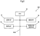
- Fig. 2 is a block diagram illustrating a main configuration of the smartphone 301.
- Fig. 3 is a block diagram illustrating a main configuration of the wireless AP 10.
- Fig. 4 is a block diagram illustrating a main configuration of the AV receiver 303. It is to be noted that, the PC 302, while the illustration is omitted, has the same configuration as the smartphone 301 and is able to perform the same operation as the smartphone 301.
- the smartphone 301 is provided with a user interface (I/F) 31, a display 32, a CPU 33, a memory 34, and a wireless module 35. Each component is connected to a common BUS.
- the user I/F 31 includes a touch panel, for example, and corresponds to a receiving portion that receives an operation from a user.
- the display 32 is a display portion and presents a user a variety of information.
- the smartphone 301 implements a GUI (Graphical User Interface) by the user I/F 31 and the display 32.
- GUI Graphic User Interface
- the wireless module 35 is a wireless communication portion in conformity with Wi-Fi standards, for example.
- the smartphone 301 is connected to the wireless AP 10 through the wireless module 35, and transmits and receives various data to and from the PC 302 or the AV receiver 303 through the wireless AP 10.
- the memory 34 stores a program for operating the CPU 33.
- the CPU 33 by reading and executing the program stored in the memory 34, performs various processing of the smartphone 301. As a result, the CPU 33 achieves the measuring portion and the radio waves strength obtaining portion in the present invention.
- the CPU 33 transmits a predetermined command according to test data, to the AV receiver 303, for example, and performs processing of receiving a response to the predetermined command.
- the wireless AP 10 is provided with a user interface (I/F) 41, an LED 42, a CPU 43, a memory 44, and a wireless module 45.
- I/F user interface
- the user I/F 41 includes a switch or the like provided in an apparatus body and receives an operation from a user.
- the LED 42 is a display portion and indicates a state (a power-on state, for example) of an own apparatus.
- the wireless module 45 is a wireless communication portion in conformity with Wi-Fi standards, for example.
- the memory 44 stores a program for operating the CPU 43.
- the CPU 43 by reading and executing the program stored in the memory 44, controls each component of the wireless AP 10 in an integrated manner. For example, the CPU 43 transmits the data that has been transmitted from the smartphone 301 to the AV receiver 303.
- the AV receiver 303 is provided with a memory 51, an HDMI receiver 52, a CPU 53, a DSP 54, a wireless module 55, and an amplifier (AMP) 56.
- a memory 51 As illustrated in Fig. 4 , the AV receiver 303 is provided with a memory 51, an HDMI receiver 52, a CPU 53, a DSP 54, a wireless module 55, and an amplifier (AMP) 56.
- AMP amplifier
- the CPU 53 by reading and executing a program stored in the memory 51, controls each component of the AV receiver 303 in an integrated manner. For example, the CPU 53 performs processing of distributing audio data as it is or as converted audio data in a predetermined encoding method, to the smartphone 301 and the PC 302 as packet data, the audio data having been input from the HDMI receiver 52.
- the DSP 54 decodes audio data, converts the audio data into a digital audio signal, and performs various audio processing to the digital audio signal.
- the various processing of the DSP 54 may be performed by software of the CPU 53.
- the AMP 56 is a circuit that amplifies an audio signal.
- the audio signal that has been amplified by the AMP 56 is converted into an analog audio signal and then is output to a not-shown speaker.
- the wireless module 55 is a wireless communication portion in conformity with Wi-Fi standards, for example.
- the AV receiver 303 is connected to the wireless AP 10 through the wireless module 55, and transmits and receives various data to and from the smartphone 301 or the PC 302 through the wireless AP 10.
- Fig. 5 illustrates an example of a structure of test data.
- the CPU 33 of the smartphone 301 transmits test data to the AV receiver 303, and receives response data as a response to the test data.
- the test data as illustrated in Fig. 5 includes a header and a body.
- the header includes information (information indicating whether a packet is test data or content data) that indicates the type of a packet, for example.
- the body includes a predetermined command for transmitting response data to test data.
- the CPU 53 of the AV receiver 303 by referring to a header, determines whether or not a received packet is test data.
- the CPU 53 of the AV receiver 303 when determining that the received packet is test data, transmits response data to the smartphone 301.
- Fig. 6 is a flow chart showing an operation of a wireless network communication system 900 at a time of transmission and reception of test data.
- the smartphone 301 transmits test data (packet data) to the AV receiver 303 through the wireless AP 10 being a relay apparatus (S11). In addition, the smartphone 301 records the transmission time of test data.
- the AV receiver 303 when receiving the data from the smartphone 301 (S21), determines whether received data is test data by referring to a header (S22). The AV receiver 303, in a case in which the received data is not the test data, performs corresponding processing. In a case in which the received data is content data, for example, the AV receiver 303 buffers the content data and performs playing processing. The AV receiver 303, in a case in which the received data is the test data, creates response data to the test data and transmits the response data (S23).
- the response data includes radio waves strength that the AV receiver 303 has detected. The detection of radio waves strength is performed by the AV receiver 303 on a regular basis.
- the smartphone 301 when receiving the data from the AV receiver 303 (S12), determines whether received data is the response data to the test data (S13).
- the smartphone 301 in a case in which the received data is not the response data, performs corresponding processing.
- the smartphone 301 buffers the content data and performs playing processing.
- the smartphone 301 in the case in which the received data is the response data, calculates a response time from a difference between the transmission time of the test data recorded previously and the reception time of the response data (S14). Then, the smartphone 301 determines whether the number of times of transmission and reception of the test data reaches the predetermined number of times (S15) .
- the transmission and reception of the test data may be performed only once, but preferably a plurality of times. In measuring a plurality of times, the smartphone 301 holds a value of each calculated response time in the memory 34.
- the smartphone 301 calculates an average value of calculated response times (S16). It is to be noted that, in a case in which a user instructs a reset by using the user I/F 31, the smartphone 301 calculates an average value by using next and subsequent measurement results. In addition, the smartphone 301, after calculating an average value, may compare the calculated average value and each response time and may determine that a response time out of a predetermined range ( ⁇ 50%, for example) is an abnormal value. In such a case, the smartphone 301 calculates an average value again by using other response times after the abnormal value is eliminated.
- a predetermined range ⁇ 50%, for example
- the smartphone 301 displays the calculated average value on the display 32 as the response time of the AV receiver 303 (S17).
- Fig. 7A and Fig. 7B illustrate a first example of a display mode of the response time on the display 32.
- the name of the apparatus the AV receiver 303
- the identification number ID: 0123456
- an information column Wireless with respect to wireless communication are displayed.
- radio waves strength and a response time are displayed as an index of a communication state.
- the actual radio waves strength is -100 dBm
- the radio waves strength to be displayed only "100" is displayed as a simplified numerical value.
- an actual measured value 0.049 (sec) is displayed.
- the information with respect to the radio waves strength may be periodically transmitted from the AV receiver 303 to the smartphone 301.
- the smartphone 301 may separately request the AV receiver 303 to transmit the information with respect to the radio waves strength.
- a user is able to grasp a communication state in the AV receiver 303 being the predetermined apparatus connected on the network by using the smartphone 301 carried by the user.
- the smartphone 301 carried by the user.
- the user is able to determine that a communication state is not good although the radio wave strength is strong in the AV receiver 303.
- displaying the radio waves strength is not essential.
- the response time becomes long.
- the response time becomes short.
- the response time serves as an index that reflects an actual communication state. Therefore, the user is able to grasp a communication state to some extent even only by seeing the display of the response time.
- Fig. 8A and Fig. 8B illustrate a second example of a display mode of the response time on the display 32.
- a response time is displayed as index information in a plurality of stages.
- "Good” is displayed as index information.
- "Bad” is displayed as index information.
- "Normal" may be displayed.
- the response time may be displayed not as an actual measured value but as index information in a plurality of stages.
- Fig. 9 is a flow chart showing an operation at a time of transmission and reception of test data.
- the smartphone 301 also transmits second test data that includes a second predetermined command to the wireless AP 10 in addition to the AV receiver 303, and measures a second response speed that indicates a response speed.
- the smartphone 301 transmits second test data (packet data) to the wireless AP 10 (S31). In addition, the smartphone 301 records the transmission time of test data.
- the wireless AP 10 when receiving the second test data from the smartphone 301 (S51), transmits second response data to the second test data (S52).
- the smartphone 301 when receiving the data from the wireless AP 10 (S32), determines whether received data is the second response data to the test data (S33) .
- the smartphone 301 in a case in which the received data is not the second response data, performs corresponding processing.
- the smartphone 301 buffers the content data and performs playing processing.
- the smartphone 301 in the case in which the received data is the second response data, calculates a second response time from a difference between the transmission time of the second test data and the reception time of the second response data (S34) . Then, the smartphone 301 determines whether the number of times of transmission and reception of the second test data reaches the predetermined number of times (S35).
- the transmission and reception of the second test data may also be performed only once, but preferably a plurality of times. In measuring a plurality of times, the smartphone 301 holds a value of each calculated second response time in the memory 34.
- the smartphone 301 in a case of determining that the number of times of transmission and reception of the second test data reaches a predetermined number of times, calculates an average value of calculated second response times (S36) .
- the smartphone 301 obtains a difference value by subtracting the calculated average value from the response time from the AV receiver 303 and displays the difference value on the display 32 as the response time of the AV receiver 303 (S37) .
- the response time calculated in S15 as illustrated in Fig. 6 is influenced by the communication state between the own apparatus (the smartphone 301) and the wireless AP 10.
- the response time displayed in S37 is obtained by subtracting the second response time from the wireless AP 10, so that only the communication state between a predetermined apparatus (the AV receiver 303) on the network excluding the influence of the own apparatus and the access point 10 is appropriately indicated.
- the smartphone 301 if grasping the configuration of the network (a connection state) (or basing on grasping information), transmits the test data to both a predetermined apparatus on a network on which a communication state is displayed and a predetermined apparatus located upstream by one from the predetermined apparatus.
- the smartphone 301 receives the response data from each of the predetermined apparatuses and measures the response time from the two predetermined apparatuses.
- the smartphone 301 by calculating a difference of the response time from the two predetermined apparatuses, measures and indicates the communication state of the predetermined apparatus alone on the network.
- the wireless communication relay apparatus such as the wireless AP 10 or a wireless LAN router is able to perform the same operation as the smartphone 301.
- the wireless AP 10 may transmit a predetermined command to other apparatuses in the network and may measure the response time.
- the wireless AP 10 may be provided with a display portion displaying a response time or may transmit the response time to the smartphone 301 or the like, for example.
- the apparatus such as the smartphone 301 or the like that has received a response time displays the response time.
- the wireless AP 10 may transmit a second predetermined command to the smartphone 301 and may measure the response speed (the second response speed). In such a case, the wireless AP 10 obtains a response time by subtracting the second response speed from the response time and transmits an obtained response time to the smartphone 301 or the like.
- the apparatus such as the smartphone 301 or the like that has received a response time displays the response time.
- the wireless AP 10 in a case of obtaining information with respect to radio waves strength, may be provided with a display portion displaying the information with respect to the radio waves strength or may transmit the information with respect to the radio waves strength to the smartphone 301 or the like, together with the response time.
- the apparatus such as the smartphone 301 or the like displays the information with respect to the radio waves strength.
Landscapes
- Engineering & Computer Science (AREA)
- Theoretical Computer Science (AREA)
- Computer Networks & Wireless Communication (AREA)
- Signal Processing (AREA)
- Human Computer Interaction (AREA)
- Physics & Mathematics (AREA)
- General Engineering & Computer Science (AREA)
- General Physics & Mathematics (AREA)
- Quality & Reliability (AREA)
- Mobile Radio Communication Systems (AREA)
- Digital Computer Display Output (AREA)
Abstract
Description
- A preferred embodiment of the present invention relates to an information processing apparatus that performs a predetermined process in network communication.
- In information processing apparatuses such as a smartphone, radio waves strength has been displayed in network communication such as wireless LAN (see Patent Literature 1, for example). Accordingly, a user is able to grasp a communication state.
- In addition, the information processing apparatuses measure actual transmission speed by transmitting and receiving test data to and from other apparatuses.
- Patent Literature 1: Japanese Unexamined Patent Application Publication No.
2015-122604 - However, the radio waves strength does not necessarily reflect an actual communication state. For example, in a case in which a noise source is present nearby or a large number of users are present, a communication state is not good in many cases even although the radio waves strength is strong.
- In addition, in order to measure transmission speed, transmission and reception of test data of a certain amount of capacity are required. Therefore, a certain amount of time is required until a result is obtained.
- In view of the foregoing, a preferred embodiment of the present invention provides an information processing apparatus, a wireless network communication system, a wireless communication relay apparatus, a program, and an information processing method that are able to immediately obtain an index that reflects an actual communication state.
- An information processing apparatus according to a preferred embodiment of the present invention includes a wireless communication portion performing wireless communication, a measuring portion transmitting a predetermined command to a predetermined apparatus through the wireless communication portion and measuring a response time, and a display portion displaying the response time.
- When a communication state is good, a response time becomes short, while, when a communication state is bad, a response time becomes long. Therefore, the information processing apparatus, by transmitting a predetermined command (test data) and measuring a response time, displays the response time as an index that reflects an actual communication state.
- In addition, a conventional information processing apparatus, by displaying the radio waves strength between an own apparatus and a relay apparatus such as a wireless access point, has presented a communication state, and, in such a case, is not able to grasp the communication state of a predetermined apparatus connected through the relay apparatus. However, the information processing apparatus of the present invention, since measuring a response time from a predetermined apparatus, is able to grasp the communication state in the predetermined apparatus.
- According to a preferred embodiment of the present invention, an index that reflects an actual communication state is able to be obtained immediately.
-
-
Fig. 1 is a diagram illustrating an overview of a wireless network communication system. -
Fig. 2 is a block diagram illustrating a configuration of a smartphone. -
Fig. 3 is a block diagram illustrating a configuration of a relay apparatus. -
Fig. 4 is a block diagram illustrating a configuration of an AV receiver. -
Fig. 5 illustrates a structure of test data. -
Fig. 6 is a flow chart showing an operation at a time of transmission and reception of test data. -
Fig. 7A and Fig. 7B illustrate a first example of a display mode of a response time. -
Fig. 8A and Fig. 8B illustrate a second example of a display mode of a response time. -
Fig. 9 is a flow chart showing an operation at a time of transmission and reception of test data according to an application example. - An information processing apparatus according to a preferred embodiment of the present invention, as described above, includes a wireless communication portion performing wireless communication, a measuring portion transmitting a predetermined command to a predetermined apparatus through the wireless communication portion and measuring a response time, and a display portion displaying the response time.
- It is to be noted that the measuring portion further transmits a second predetermined command to a relay apparatus and measures a second response speed that indicates a response speed and the display portion displays a response time obtained by subtracting the second response speed and is thus able to appropriately grasp only the communication state of the predetermined apparatus.
- In addition, the information processing apparatus may display information with respect to radio waves strength, together with a response time. In such a case, the information processing apparatus obtains the information with respect to the radio waves strength in the predetermined apparatus.
- In addition, the measuring portion, as the response time, may calculate an average value of a plurality of times of measurement. Further, the information processing apparatus includes a receiving portion receiving an operation of a user, and the measuring portion, when receiving a reset instruction from the user, calculates an average value by using next and subsequent measurement results.
- In addition, the response time may be displayed as index information in a plurality of stages (such as "good," "normal," and "bad," for example).
- Hereinafter, a description is made of a specific configuration.
Fig. 1 is a diagram illustrating an overview of a wirelessnetwork communication system 900. The wirelessnetwork communication system 900 is provided with a wireless access point (AP) 10 being a relay apparatus, asmartphone 301 being an example of an information processing apparatus, a personal computer (PC) 302, and anAV receiver 303. - The
smartphone 301, the PC 302, and theAV receiver 303 are connected to one another in a network through thewireless AP 10. - The wireless
network communication system 900, for example, streaming-distributes content data (audio data) that is being played on theAV receiver 303 to thesmartphone 301 and the PC 302, and performs synchronous playing on all the apparatuses. Thus, a user listens to audio that is being played on theAV receiver 303 in a living room, for example, and then moves to another room (a bedroom, for example), and is able to continuously listen to the audio by using thesmartphone 301. - In the wireless
network communication system 900 inFig. 1 , theAV receiver 303 serves as a server and distributes audio data to thesmartphone 301 and the PC 302 being clients. However, thesmartphone 301 and the PC 302 may serve as a server that distributes audio data, and theAV receiver 303 may be a client. - In this manner, in a case of distributing audio data through wireless network communication, it becomes important to grasp a communication state in a server (the
AV receiver 303, for example) . Therefore, in the wirelessnetwork communication system 900, a user is able to grasp the communication state of a predetermined apparatus (the AV receiver 303) by using an information processing apparatus (thesmartphone 301, for example) carried by the user. Hereinafter, a description is made of a configuration to grasp the communication state. -
Fig. 2 is a block diagram illustrating a main configuration of thesmartphone 301.Fig. 3 is a block diagram illustrating a main configuration of thewireless AP 10.Fig. 4 is a block diagram illustrating a main configuration of theAV receiver 303. It is to be noted that, the PC 302, while the illustration is omitted, has the same configuration as thesmartphone 301 and is able to perform the same operation as thesmartphone 301. - The
smartphone 301 is provided with a user interface (I/F) 31, adisplay 32, aCPU 33, amemory 34, and awireless module 35. Each component is connected to a common BUS. - The user I/
F 31 includes a touch panel, for example, and corresponds to a receiving portion that receives an operation from a user. Thedisplay 32 is a display portion and presents a user a variety of information. Thesmartphone 301 implements a GUI (Graphical User Interface) by the user I/F 31 and thedisplay 32. - The
wireless module 35 is a wireless communication portion in conformity with Wi-Fi standards, for example. Thesmartphone 301 is connected to thewireless AP 10 through thewireless module 35, and transmits and receives various data to and from thePC 302 or theAV receiver 303 through thewireless AP 10. - The
memory 34 stores a program for operating theCPU 33. TheCPU 33, by reading and executing the program stored in thememory 34, performs various processing of thesmartphone 301. As a result, theCPU 33 achieves the measuring portion and the radio waves strength obtaining portion in the present invention. TheCPU 33 transmits a predetermined command according to test data, to theAV receiver 303, for example, and performs processing of receiving a response to the predetermined command. - As illustrated in
Fig. 3 , thewireless AP 10 is provided with a user interface (I/F) 41, an LED 42, aCPU 43, amemory 44, and awireless module 45. - The user I/
F 41 includes a switch or the like provided in an apparatus body and receives an operation from a user. The LED 42 is a display portion and indicates a state (a power-on state, for example) of an own apparatus. - The
wireless module 45 is a wireless communication portion in conformity with Wi-Fi standards, for example. Thememory 44 stores a program for operating theCPU 43. TheCPU 43, by reading and executing the program stored in thememory 44, controls each component of thewireless AP 10 in an integrated manner. For example, theCPU 43 transmits the data that has been transmitted from thesmartphone 301 to theAV receiver 303. - As illustrated in
Fig. 4 , theAV receiver 303 is provided with amemory 51, anHDMI receiver 52, aCPU 53, aDSP 54, awireless module 55, and an amplifier (AMP) 56. - The
CPU 53, by reading and executing a program stored in thememory 51, controls each component of theAV receiver 303 in an integrated manner. For example, theCPU 53 performs processing of distributing audio data as it is or as converted audio data in a predetermined encoding method, to thesmartphone 301 and thePC 302 as packet data, the audio data having been input from theHDMI receiver 52. - The
DSP 54 decodes audio data, converts the audio data into a digital audio signal, and performs various audio processing to the digital audio signal. However, the various processing of theDSP 54 may be performed by software of theCPU 53. - The
AMP 56 is a circuit that amplifies an audio signal. The audio signal that has been amplified by theAMP 56 is converted into an analog audio signal and then is output to a not-shown speaker. - The
wireless module 55 is a wireless communication portion in conformity with Wi-Fi standards, for example. TheAV receiver 303 is connected to thewireless AP 10 through thewireless module 55, and transmits and receives various data to and from thesmartphone 301 or thePC 302 through thewireless AP 10. -
Fig. 5 illustrates an example of a structure of test data. As stated above, theCPU 33 of thesmartphone 301 transmits test data to theAV receiver 303, and receives response data as a response to the test data. The test data as illustrated inFig. 5 includes a header and a body. - The header includes information (information indicating whether a packet is test data or content data) that indicates the type of a packet, for example. The body includes a predetermined command for transmitting response data to test data. The
CPU 53 of theAV receiver 303, by referring to a header, determines whether or not a received packet is test data. TheCPU 53 of theAV receiver 303, when determining that the received packet is test data, transmits response data to thesmartphone 301. -
Fig. 6 is a flow chart showing an operation of a wirelessnetwork communication system 900 at a time of transmission and reception of test data. - To begin with, the
smartphone 301 transmits test data (packet data) to theAV receiver 303 through thewireless AP 10 being a relay apparatus (S11). In addition, thesmartphone 301 records the transmission time of test data. - The
AV receiver 303, when receiving the data from the smartphone 301 (S21), determines whether received data is test data by referring to a header (S22). TheAV receiver 303, in a case in which the received data is not the test data, performs corresponding processing. In a case in which the received data is content data, for example, theAV receiver 303 buffers the content data and performs playing processing. TheAV receiver 303, in a case in which the received data is the test data, creates response data to the test data and transmits the response data (S23). The response data includes radio waves strength that theAV receiver 303 has detected. The detection of radio waves strength is performed by theAV receiver 303 on a regular basis. - The
smartphone 301, when receiving the data from the AV receiver 303 (S12), determines whether received data is the response data to the test data (S13). Thesmartphone 301, in a case in which the received data is not the response data, performs corresponding processing. In a case in which the received data is content data, for example, thesmartphone 301 buffers the content data and performs playing processing. Thesmartphone 301, in the case in which the received data is the response data, calculates a response time from a difference between the transmission time of the test data recorded previously and the reception time of the response data (S14). Then, thesmartphone 301 determines whether the number of times of transmission and reception of the test data reaches the predetermined number of times (S15) . The transmission and reception of the test data may be performed only once, but preferably a plurality of times. In measuring a plurality of times, thesmartphone 301 holds a value of each calculated response time in thememory 34. - Subsequently, the
smartphone 301, in the case in which the test data is transmitted a predetermined number of times, calculates an average value of calculated response times (S16). It is to be noted that, in a case in which a user instructs a reset by using the user I/F 31, thesmartphone 301 calculates an average value by using next and subsequent measurement results. In addition, thesmartphone 301, after calculating an average value, may compare the calculated average value and each response time and may determine that a response time out of a predetermined range (±50%, for example) is an abnormal value. In such a case, thesmartphone 301 calculates an average value again by using other response times after the abnormal value is eliminated. - At the end, the
smartphone 301 displays the calculated average value on thedisplay 32 as the response time of the AV receiver 303 (S17). -
Fig. 7A and Fig. 7B illustrate a first example of a display mode of the response time on thedisplay 32. On thedisplay 32, as illustrated inFig. 7A , for example, the name of the apparatus (the AV receiver 303), the identification number (ID: 0123456) of the apparatus, and an information column (Wireless) with respect to wireless communication are displayed. - In this example, radio waves strength and a response time are displayed as an index of a communication state. In this example, although the actual radio waves strength is -100 dBm, as the radio waves strength to be displayed, only "100" is displayed as a simplified numerical value. In addition, as a response time, an actual measured value, 0.049 (sec), is displayed.
- It is to be noted that the information with respect to the radio waves strength may be periodically transmitted from the
AV receiver 303 to thesmartphone 301. Alternatively, thesmartphone 301 may separately request theAV receiver 303 to transmit the information with respect to the radio waves strength. - As a result, a user is able to grasp a communication state in the
AV receiver 303 being the predetermined apparatus connected on the network by using thesmartphone 301 carried by the user. For example, as illustrated inFig. 7B , in a case in which the radio waves strength is displayed as "100" and the response time is displayed as "1.300," the user is able to determine that a communication state is not good although the radio wave strength is strong in theAV receiver 303. - It is to be noted that displaying the radio waves strength is not essential. For example, in a situation in which a communication state is not good due to the presence of a noise source nearby or the presence of a large number of users, the response time becomes long. On the other hand, in a situation in which a communication state is good, the response time becomes short. In other words, the response time serves as an index that reflects an actual communication state. Therefore, the user is able to grasp a communication state to some extent even only by seeing the display of the response time.
- Next,
Fig. 8A and Fig. 8B illustrate a second example of a display mode of the response time on thedisplay 32. In this example, a response time is displayed as index information in a plurality of stages. For example, as illustrated inFig. 8A , in a case in which the response time is short (in a case of less than 100 msec, for example), "Good" is displayed as index information. In addition, as illustrated inFig. 8B , in a case in which the response time is long (in a case of not less than 1 sec, for example), "Bad" is displayed as index information. In a case in which the response time is 100 msec to 1 sec, "Normal" may be displayed. - In this example, the response time may be displayed not as an actual measured value but as index information in a plurality of stages.
- Subsequently,
Fig. 9 is a flow chart showing an operation at a time of transmission and reception of test data. In this example, thesmartphone 301 also transmits second test data that includes a second predetermined command to thewireless AP 10 in addition to theAV receiver 303, and measures a second response speed that indicates a response speed. - To begin with, the
smartphone 301 transmits second test data (packet data) to the wireless AP 10 (S31). In addition, thesmartphone 301 records the transmission time of test data. - The
wireless AP 10, when receiving the second test data from the smartphone 301 (S51), transmits second response data to the second test data (S52). - The
smartphone 301, when receiving the data from the wireless AP 10 (S32), determines whether received data is the second response data to the test data (S33) . Thesmartphone 301, in a case in which the received data is not the second response data, performs corresponding processing. In a case in which the received data is content data, for example, thesmartphone 301 buffers the content data and performs playing processing. - The
smartphone 301, in the case in which the received data is the second response data, calculates a second response time from a difference between the transmission time of the second test data and the reception time of the second response data (S34) . Then, thesmartphone 301 determines whether the number of times of transmission and reception of the second test data reaches the predetermined number of times (S35). The transmission and reception of the second test data may also be performed only once, but preferably a plurality of times. In measuring a plurality of times, thesmartphone 301 holds a value of each calculated second response time in thememory 34. - Subsequently, the
smartphone 301, in a case of determining that the number of times of transmission and reception of the second test data reaches a predetermined number of times, calculates an average value of calculated second response times (S36) . - At the end, the
smartphone 301 obtains a difference value by subtracting the calculated average value from the response time from theAV receiver 303 and displays the difference value on thedisplay 32 as the response time of the AV receiver 303 (S37) . - The response time calculated in S15 as illustrated in
Fig. 6 is influenced by the communication state between the own apparatus (the smartphone 301) and thewireless AP 10. However, in the preferred embodiment inFig. 9 , the response time displayed in S37 is obtained by subtracting the second response time from thewireless AP 10, so that only the communication state between a predetermined apparatus (the AV receiver 303) on the network excluding the influence of the own apparatus and theaccess point 10 is appropriately indicated. - Further, as another preferred embodiment, the
smartphone 301, if grasping the configuration of the network (a connection state) (or basing on grasping information), transmits the test data to both a predetermined apparatus on a network on which a communication state is displayed and a predetermined apparatus located upstream by one from the predetermined apparatus. Thesmartphone 301 receives the response data from each of the predetermined apparatuses and measures the response time from the two predetermined apparatuses. Thesmartphone 301, by calculating a difference of the response time from the two predetermined apparatuses, measures and indicates the communication state of the predetermined apparatus alone on the network. - It is to be noted that the foregoing preferred embodiments are illustrative in all points and should not be construed to limit the present invention. The scope of the present invention is defined not by the foregoing preferred embodiment but by the following claims. Further, the scope of the present invention is intended to include all modifications within the scopes of the claims and within the meanings and scopes of equivalents.
- The wireless communication relay apparatus such as the
wireless AP 10 or a wireless LAN router is able to perform the same operation as thesmartphone 301. For example, thewireless AP 10 may transmit a predetermined command to other apparatuses in the network and may measure the response time. In such a case, thewireless AP 10 may be provided with a display portion displaying a response time or may transmit the response time to thesmartphone 301 or the like, for example. The apparatus such as thesmartphone 301 or the like that has received a response time displays the response time. - Further, the
wireless AP 10 may transmit a second predetermined command to thesmartphone 301 and may measure the response speed (the second response speed). In such a case, thewireless AP 10 obtains a response time by subtracting the second response speed from the response time and transmits an obtained response time to thesmartphone 301 or the like. The apparatus such as thesmartphone 301 or the like that has received a response time displays the response time. - In addition, the
wireless AP 10, in a case of obtaining information with respect to radio waves strength, may be provided with a display portion displaying the information with respect to the radio waves strength or may transmit the information with respect to the radio waves strength to thesmartphone 301 or the like, together with the response time. The apparatus such as thesmartphone 301 or the like displays the information with respect to the radio waves strength. -
- 10
- - Wireless AP
- 31
- - User I/F
- 32
- - Display
- 33
- - CPU
- 34
- - Memory
- 35
- - Wireless module
- 42
- - LED
- 43
- - CPU
- 44
- - Memory
- 45
- - Wireless module
- 51
- - Memory
- 52
- - HDMI receiver
- 53
- - CPU
- 54
- - DSP
- 55
- - Wireless module
- 301
- - Smartphone
- 302
- - PC
- 303
- - AV receiver
- 900
- - Wireless network communication system
Claims (16)
- An information processing apparatus comprising:a wireless communication portion performing wireless communication;a measuring portion transmitting a predetermined command to a predetermined apparatus through the wireless communication portion and measuring a response time; anda display portion displaying the response time.
- The information processing apparatus according to claim 1, wherein:the measuring portion further transmits a second predetermined command to a relay apparatus and measures a second response speed that indicates a response speed; andthe display portion displays a response time obtained by subtracting the second response speed.
- The information processing apparatus according to claim 1 or 2, further comprising a radio waves strength obtaining portion obtaining information with respect to radio waves strength of the predetermined apparatus, wherein the display portion displays the information with respect to the radio waves strength, together with the response time.
- The information processing apparatus according to any one of claims 1 to 3, wherein the measuring portion, as the response time, calculates an average value of a plurality of times of measurement.
- The information processing apparatus according to claim 4, comprising a receiving portion receiving an operation of a user, wherein the measuring portion, when receiving a reset instruction from the user, calculates the average value by using next and subsequent measurement results.
- The information processing apparatus according to any one of claims 1 to 5, wherein the response time is displayed as index information in a plurality of stages.
- A wireless network communication system comprising:the information processing apparatus according to any one of claims 1 to 6; andthe predetermined apparatus being a server distributing audio data.
- The wireless network communication system according to claim 7, further comprising a client receiving distribution of the audio data from the predetermined apparatus, wherein the wireless network communication system performs synchronous play with the server and the client.
- A wireless communication relay apparatus comprising:a wireless communication portion performing wireless communication;a measuring portion transmitting a predetermined command to a predetermined apparatus through the wireless communication portion and measuring a response time; anda transmitting portion transmitting the response time.
- The wireless communication relay apparatus according to claim 9, wherein:the measuring portion further transmits a second predetermined command to a relay apparatus and measures a second response speed that indicates a response speed; andthe transmitting portion transmits a response time obtained by subtracting the second response speed.
- The wireless communication relay apparatus according to claim 9 or 10, further comprising a radio waves strength obtaining portion obtaining information with respect to radio waves strength of the predetermined apparatus, wherein the transmitting portion transmits the information with respect to the radio waves strength, together with the response time.
- The wireless communication relay apparatus according to any one of claims 9 to 11, wherein the measuring portion, as the response time, calculates an average value of a plurality of times of measurement.
- The wireless communication relay apparatus according to claim 12, comprising a receiving portion receiving an operation of a user, wherein the measuring portion, when receiving a reset instruction from the user, calculates the average value by using next and subsequent measurement results.
- The wireless communication relay apparatus according to any one of claims 9 to 13, wherein the response time is transmitted as index information in a plurality of stages.
- A program that causes an information processing apparatus provided with a wireless communication portion performing wireless communication to execute processing comprising:transmitting a predetermined command to a predetermined apparatus through the wireless communication portion and measuring a response time; anddisplaying the response time.
- An information processing method of executing processing comprising:transmitting a predetermined command to a predetermined apparatus through a wireless communication portion and measuring a response time; anddisplaying the response time.
Applications Claiming Priority (2)
| Application Number | Priority Date | Filing Date | Title |
|---|---|---|---|
| JP2015242796A JP6508025B2 (en) | 2015-12-14 | 2015-12-14 | INFORMATION PROCESSING APPARATUS, PROGRAM, AND INFORMATION PROCESSING METHOD |
| PCT/JP2016/086850 WO2017104593A1 (en) | 2015-12-14 | 2016-12-12 | Information processing device, wireless network communication system, wireless communication relay device, program and information processing method |
Publications (2)
| Publication Number | Publication Date |
|---|---|
| EP3393064A1 true EP3393064A1 (en) | 2018-10-24 |
| EP3393064A4 EP3393064A4 (en) | 2019-07-10 |
Family
ID=59056579
Family Applications (1)
| Application Number | Title | Priority Date | Filing Date |
|---|---|---|---|
| EP16875570.0A Withdrawn EP3393064A4 (en) | 2015-12-14 | 2016-12-12 | INFORMATION PROCESSING DEVICE, WIRELESS NETWORK COMMUNICATION SYSTEM, WIRELESS COMMUNICATION RELAY DEVICE, PROGRAM, AND INFORMATION PROCESSING METHOD |
Country Status (5)
| Country | Link |
|---|---|
| US (1) | US10631185B2 (en) |
| EP (1) | EP3393064A4 (en) |
| JP (1) | JP6508025B2 (en) |
| CN (1) | CN108432162B (en) |
| WO (1) | WO2017104593A1 (en) |
Families Citing this family (2)
| Publication number | Priority date | Publication date | Assignee | Title |
|---|---|---|---|---|
| WO2022269904A1 (en) * | 2021-06-25 | 2022-12-29 | 日本電信電話株式会社 | System, method, apparatus, and program for measuring delay in device |
| JP7567875B2 (en) * | 2022-08-09 | 2024-10-16 | カシオ計算機株式会社 | Electronic device, electronic device control method, and program |
Family Cites Families (17)
| Publication number | Priority date | Publication date | Assignee | Title |
|---|---|---|---|---|
| JPH08205253A (en) * | 1995-01-27 | 1996-08-09 | Fuji Electric Co Ltd | Low power wireless information collection system |
| JP2001036545A (en) * | 1999-05-17 | 2001-02-09 | Sony Corp | Information processing apparatus and method, information processing system, and medium |
| JP4079577B2 (en) * | 2000-06-05 | 2008-04-23 | ヤマハ株式会社 | An audio data distribution system, a distribution method, a distribution server used in the distribution system, a client-side terminal, and a computer-readable recording medium storing a program applied to a computer used in the distribution system. |
| US7333794B2 (en) * | 2001-03-06 | 2008-02-19 | At&T Mobility Ii Llc | Real-time network analysis and performance management |
| CN100466672C (en) * | 2001-07-18 | 2009-03-04 | 雅马哈株式会社 | Voice data transmission system and method, its transmission server and client terminal |
| JP2003258710A (en) * | 2002-02-28 | 2003-09-12 | Hitachi Kokusai Electric Inc | How to adjust the antenna orientation |
| US20040263424A1 (en) * | 2003-06-30 | 2004-12-30 | Okuley James M. | Display system and method |
| JP2006324945A (en) * | 2005-05-19 | 2006-11-30 | Matsushita Electric Ind Co Ltd | Communication terminal device |
| US20070233694A1 (en) * | 2006-03-31 | 2007-10-04 | Baxter Robert A | Configuring interactive media systems based on performance metrics |
| JP4899767B2 (en) * | 2006-10-06 | 2012-03-21 | ソニー株式会社 | Data communication apparatus, data communication method, and program |
| JP4424382B2 (en) * | 2007-07-04 | 2010-03-03 | ソニー株式会社 | Content reproduction apparatus and content automatic reception method |
| US8306013B2 (en) * | 2009-01-23 | 2012-11-06 | Empire Technology Development Llc | Interactions among mobile devices in a wireless network |
| JP6269038B2 (en) | 2013-12-24 | 2018-01-31 | 株式会社バッファロー | Wireless communication system, wireless communication apparatus, and computer program |
| JP6327921B2 (en) * | 2014-04-22 | 2018-05-23 | 三菱電機株式会社 | Repeater and air conditioning system |
| JP6330617B2 (en) * | 2014-10-21 | 2018-05-30 | ソニー株式会社 | Information processing apparatus, communication system, information processing method, and program |
| JP6007266B2 (en) * | 2015-01-27 | 2016-10-12 | Kddi株式会社 | Communication apparatus, communication system, determination method, and communication program |
| JP5966040B1 (en) * | 2015-03-24 | 2016-08-10 | Kddi株式会社 | Communication apparatus and calculation method |
-
2015
- 2015-12-14 JP JP2015242796A patent/JP6508025B2/en not_active Expired - Fee Related
-
2016
- 2016-12-12 CN CN201680073413.XA patent/CN108432162B/en active Active
- 2016-12-12 EP EP16875570.0A patent/EP3393064A4/en not_active Withdrawn
- 2016-12-12 WO PCT/JP2016/086850 patent/WO2017104593A1/en not_active Ceased
-
2018
- 2018-02-20 US US15/900,196 patent/US10631185B2/en active Active
Also Published As
| Publication number | Publication date |
|---|---|
| US20180176808A1 (en) | 2018-06-21 |
| JP6508025B2 (en) | 2019-05-08 |
| JP2017112398A (en) | 2017-06-22 |
| CN108432162A (en) | 2018-08-21 |
| US10631185B2 (en) | 2020-04-21 |
| CN108432162B (en) | 2021-06-22 |
| EP3393064A4 (en) | 2019-07-10 |
| WO2017104593A1 (en) | 2017-06-22 |
Similar Documents
| Publication | Publication Date | Title |
|---|---|---|
| CN107566053B (en) | Test method, system and computer-readable storage medium for radio frequency index | |
| US20160128121A1 (en) | Terminal device, remote control system, and remote control target determination method therefor | |
| US9699579B2 (en) | Networked speaker system with follow me | |
| JP5664276B2 (en) | Radio wave status display system, user terminal, router, radio wave status display method and program | |
| US9179341B2 (en) | Method and system for simplifying WiFi setup for best performance | |
| US10091676B2 (en) | Signal measurement using paired remote device | |
| CN108199789B (en) | Bluetooth signal adjustment method, device, test terminal, system and readable medium | |
| US9612133B2 (en) | Smart meter system communication methods | |
| US10631185B2 (en) | Information processing apparatus, wireless network communication system, wireless communication relay apparatus, and information processing method | |
| WO2018156103A1 (en) | Audio signal routing to audio devices | |
| US20170034859A1 (en) | Operating environment setting system of electronic device, operating environment setting method and operating environment setting program | |
| CN105044658A (en) | Wireless signal characteristic generation method, detector and server | |
| CN113325404A (en) | Method and device for measuring equipment distance and electronic equipment | |
| US8634382B2 (en) | Station device and method of checking communication performance thereof | |
| US10269231B2 (en) | Sound generation | |
| KR20200074599A (en) | Electronic device and control method thereof | |
| US7457712B1 (en) | Distributed test equipment system for testing analog communications systems | |
| CN110545125B (en) | Radio frequency cable measuring device and method | |
| KR101874524B1 (en) | WiFi association-free based communication method | |
| CN115333651B (en) | Data link system receiving sensitivity test system and application method thereof | |
| US20060079256A1 (en) | Apparatus for measuring FA wireless communication propagation environment and method thereof | |
| KR20090065055A (en) | Remote Wireless Instrument Control System Using Zigbee Communication | |
| JP2012070065A (en) | Radio communication speed detection device and method for operating the same | |
| EP4725278A1 (en) | Apparatus and methods for testing computing device wireless functionality | |
| CN111447119A (en) | Audio time delay obtaining method, device, equipment and computer readable storage medium |
Legal Events
| Date | Code | Title | Description |
|---|---|---|---|
| STAA | Information on the status of an ep patent application or granted ep patent |
Free format text: STATUS: THE INTERNATIONAL PUBLICATION HAS BEEN MADE |
|
| PUAI | Public reference made under article 153(3) epc to a published international application that has entered the european phase |
Free format text: ORIGINAL CODE: 0009012 |
|
| STAA | Information on the status of an ep patent application or granted ep patent |
Free format text: STATUS: REQUEST FOR EXAMINATION WAS MADE |
|
| 17P | Request for examination filed |
Effective date: 20180613 |
|
| AK | Designated contracting states |
Kind code of ref document: A1 Designated state(s): AL AT BE BG CH CY CZ DE DK EE ES FI FR GB GR HR HU IE IS IT LI LT LU LV MC MK MT NL NO PL PT RO RS SE SI SK SM TR |
|
| AX | Request for extension of the european patent |
Extension state: BA ME |
|
| DAV | Request for validation of the european patent (deleted) | ||
| DAX | Request for extension of the european patent (deleted) | ||
| A4 | Supplementary search report drawn up and despatched |
Effective date: 20190613 |
|
| RIC1 | Information provided on ipc code assigned before grant |
Ipc: G06F 3/14 20060101ALI20190606BHEP Ipc: H04B 17/309 20150101AFI20190606BHEP Ipc: H04W 24/08 20090101ALI20190606BHEP |
|
| STAA | Information on the status of an ep patent application or granted ep patent |
Free format text: STATUS: EXAMINATION IS IN PROGRESS |
|
| 17Q | First examination report despatched |
Effective date: 20210507 |
|
| GRAP | Despatch of communication of intention to grant a patent |
Free format text: ORIGINAL CODE: EPIDOSNIGR1 |
|
| STAA | Information on the status of an ep patent application or granted ep patent |
Free format text: STATUS: GRANT OF PATENT IS INTENDED |
|
| INTG | Intention to grant announced |
Effective date: 20250415 |
|
| STAA | Information on the status of an ep patent application or granted ep patent |
Free format text: STATUS: THE APPLICATION IS DEEMED TO BE WITHDRAWN |
|
| 18D | Application deemed to be withdrawn |
Effective date: 20250819 |