EP3393048A1 - Card holder, inserting device and terminal - Google Patents
Card holder, inserting device and terminal Download PDFInfo
- Publication number
- EP3393048A1 EP3393048A1 EP18150569.4A EP18150569A EP3393048A1 EP 3393048 A1 EP3393048 A1 EP 3393048A1 EP 18150569 A EP18150569 A EP 18150569A EP 3393048 A1 EP3393048 A1 EP 3393048A1
- Authority
- EP
- European Patent Office
- Prior art keywords
- card
- card slot
- sliding block
- side wall
- holder
- Prior art date
- Legal status (The legal status is an assumption and is not a legal conclusion. Google has not performed a legal analysis and makes no representation as to the accuracy of the status listed.)
- Granted
Links
Images




Classifications
-
- H—ELECTRICITY
- H01—ELECTRIC ELEMENTS
- H01R—ELECTRICALLY-CONDUCTIVE CONNECTIONS; STRUCTURAL ASSOCIATIONS OF A PLURALITY OF MUTUALLY-INSULATED ELECTRICAL CONNECTING ELEMENTS; COUPLING DEVICES; CURRENT COLLECTORS
- H01R13/00—Details of coupling devices of the kinds covered by groups H01R12/70 or H01R24/00 - H01R33/00
- H01R13/62—Means for facilitating engagement or disengagement of coupling parts or for holding them in engagement
- H01R13/629—Additional means for facilitating engagement or disengagement of coupling parts, e.g. aligning or guiding means, levers, gas pressure electrical locking indicators, manufacturing tolerances
-
- H—ELECTRICITY
- H01—ELECTRIC ELEMENTS
- H01R—ELECTRICALLY-CONDUCTIVE CONNECTIONS; STRUCTURAL ASSOCIATIONS OF A PLURALITY OF MUTUALLY-INSULATED ELECTRICAL CONNECTING ELEMENTS; COUPLING DEVICES; CURRENT COLLECTORS
- H01R13/00—Details of coupling devices of the kinds covered by groups H01R12/70 or H01R24/00 - H01R33/00
- H01R13/62—Means for facilitating engagement or disengagement of coupling parts or for holding them in engagement
- H01R13/639—Additional means for holding or locking coupling parts together, after engagement, e.g. separate keylock, retainer strap
-
- H—ELECTRICITY
- H04—ELECTRIC COMMUNICATION TECHNIQUE
- H04B—TRANSMISSION
- H04B1/00—Details of transmission systems, not covered by a single one of groups H04B3/00 - H04B13/00; Details of transmission systems not characterised by the medium used for transmission
- H04B1/38—Transceivers, i.e. devices in which transmitter and receiver form a structural unit and in which at least one part is used for functions of transmitting and receiving
- H04B1/3816—Mechanical arrangements for accommodating identification devices, e.g. cards or chips; with connectors for programming identification devices
- H04B1/3818—Arrangements for facilitating insertion or removal of identification devices
-
- H—ELECTRICITY
- H01—ELECTRIC ELEMENTS
- H01R—ELECTRICALLY-CONDUCTIVE CONNECTIONS; STRUCTURAL ASSOCIATIONS OF A PLURALITY OF MUTUALLY-INSULATED ELECTRICAL CONNECTING ELEMENTS; COUPLING DEVICES; CURRENT COLLECTORS
- H01R2201/00—Connectors or connections adapted for particular applications
- H01R2201/16—Connectors or connections adapted for particular applications for telephony
Definitions
- the present disclosure relates to a technical field of electronic equipment, and more particularly, to a card holder, an inserting device and a terminal.
- a data card is usually placed on a card holder, and the card holder with the data card is then disposed in a card socket, so as to achieve electric connection between the data card and an electronic device.
- a coupling between the data card and the card holder is not stable enough, and the data card is easily detached from the card holder and falls off when the card holder is flipped over.
- Embodiments of the present disclosure provide a card holder, an inserting device and a terminal.
- the card holder includes a card tray defining a card slot and a sliding groove in communication with the card slot, the card slot being configured to receive the data card; a sliding block capable of sliding along the sliding groove; and an elastic element coupled to the sliding block, fixed to the card tray, and configured to press the sliding block to make the sliding block abut against the data card when the elastic element is in a deformation state.
- the card tray further includes a first surface and a second surface opposite the first surface, the card slot is defined in the first surface and the sliding groove is defined in the first surface.
- the card tray further includes a first surface and a second surface opposite the first surface;
- the card slot includes a first card slot defined in the first surface and a second card slot defined in the second surface;
- the sliding groove is defined in the first surface, and passes through the first card slot and partially penetrates into the second card slot in a depth direction; the sliding block is able to abut against the data card when the data card is received in the first card slot, or when the data card is received in the second card slot, or when the date card is received in each of the first card slot and the second card slot.
- the card tray further includes a partition plate provided between the first card slot and the second card slot, and the partition plate is configured to separate the data card received in the first card slot from the data card received in the second card slot.
- the card tray further includes a fixing groove defined in the first surface, the fixing groove is in communication with the sliding groove, and the elastic element is received in the fixing groove;
- the fixing groove includes a first wall adjacent to the card slot and a second wall opposite the first wall, and the second wall gradually extends away from the card slot along a direction from two ends of the fixing groove to a middle position of the fixing groove.
- two ends of the elastic element are fixed at the two ends of the fixing groove.
- the elastic element is able to abut against an inner wall of the fixing groove.
- the sliding block slides in the sliding groove along a direction perpendicular to a length direction of the elastic element, and the elastic element penetrates the sliding block or extends outwardly from two sides of the sliding block.
- the sliding block is located in a middle position in the length direction of the elastic element, and a sliding direction of the sliding block within the sliding groove is aligned with a middle position of the card slot.
- the card holder further includes a handle coupled to an end of the card tray, the sliding groove being located between the card slot and the handle.
- the card tray exhibits a rectangular parallelepiped shape overall, and the card slot is defined by four side walls coupled end to end, the side walls including a first side wall, a second side wall, a third side wall and a fourth side wall.
- first side wall and the third side wall are opposite and extend along a second direction; the second side wall and the fourth side wall are opposite and extend along a first direction; the second side wall couples a first end of the first side wall and a first end of the third side wall, while the fourth side wall couples a second end of the first side wall and a second end of the third side wall.
- the sliding block when the data card is not received in the card slot, the sliding block is inserted into the card slot by a first depth along the first direction; when the data card is received in the card slot, the sliding block is inserted into the card slot by a second depth along the first direction, and the first depth is greater than the second depth.
- the inserting device includes a card socket defining an accommodating space; and a card holder according to any one of the above embodiments, capable of being movably inserted into or drawn out of the accommodating space.
- the terminal according to embodiments of the present disclosure includes a card holder according to any one of the above embodiments.
- the elastic element can press the sliding block in the deformation state, such that the sliding block can abut against the data card when the data card is received in the card slot, and hence the data card can be firmly installed on the card holder and will not be detached from the card holder when the card holder is flipped over.
- Inserting device 100 card socket 10, accommodating space 12, card holder 20, card tray 21, card slot 211, upper card slot 2111, lower card slot 2112, sliding groove 212, first side wall 213, second side wall 214, third side wall 215, end portion 2152, middle portion 2154, fourth side wall 216, upper surface 217, lower surface 218, fixing groove 219, first wall 2191, second wall 2192, partition plate 21a, sliding block 22, abutting surface 222, elastic element 23, handle 24, terminal 200, metal contact 30, data card 300.
- a structure in which a first feature is "on" or “below” a second feature may include an embodiment in which the first feature is in direct contact with the second feature, and may also include an embodiment in which the first feature and the second feature are not in direct contact with each other, but are contacted via an additional feature formed therebetween.
- a first feature "on,” “above,” or “on top of' a second feature may include an embodiment in which the first feature is right or obliquely “on,” “above,” or “on top of' the second feature, or just means that the first feature is at a height higher than that of the second feature; while a first feature "below,” “under,” or “on bottom of' a second feature may include an embodiment in which the first feature is right or obliquely “below,” “under,” or “on bottom of' the second feature, or just means that the first feature is at a height lower than that of the second feature.
- a card holder 20 is configured to install a data card 300, and includes a card tray 21, a sliding block 22 and an elastic element 23.
- the data card 300 can be a SIM card, a TF card, a SD card or the like.
- An inserting device 100 includes the card holder 20 and a card socket 10, the card socket 10 defines an accommodating space 12, and the card holder 20 can be movably inserted into or drawn out of the accommodating space 12. Specifically, the card holder 20 can be completely or partially drawn out of the card socket 10, and after the data card 300 is installed in the card holder 20, the card holder 20 is then pushed into the card socket 10.
- the card socket 10 also includes a contact terminal (not illustrated), and when the data card 300 is installed in the card holder 20 and pushed into the accommodating space 12, the contact terminal makes contact with a metal contact 30 of the data card 300 so that the contact terminal can read data from or write data into the data card 300.
- a terminal 200 includes the card holder 20. Further, the terminal 200 also includes the card socket 10.
- the terminal 200 may be various devices that can acquire data from the data card 300 and process the data, or that can import data into the data card 300, and for example, the terminal 200 can be a mobile phone, a tablet computer, a computing device, an information display device, or the like.
- the card tray 21 defines a card slot 211 and a sliding groove 212.
- the card slot 211 is configured to receive the data card 300, and the card slot 211 is in communication with the sliding groove 212.
- the card tray 21 exhibits a rectangular parallelepiped shape overall, and the card slot 211 is defined by four side walls coupled end to end, the side walls including a first side wall 213, a second side wall 214, a third side wall 215 and a fourth side wall 216.
- the third side wall 215 is first inserted into the accommodating space 12, and then the card holder 20 is pushed into the card socket 10 along a first direction.
- the first side wall 213 and the third side wall 215 are opposite and extend along a second direction; the second side wall 214 and the fourth side wall 216 are opposite and extend along the first direction; the third side wall 215 is the side wall inserted deepest when the card holder 20 is inserted into the accommodating space 12, while the first side wall 213 is the side wall inserted most shallowly when the card holder 20 is inserted into the accommodating space 12; the second side wall 214 couples a first end of the first side wall 213 and a first end of the third side wall 215, while the fourth side wall 216 couples a second end of the first side wall 213 and a second end of the third side wall 215.
- the first direction refers to a direction in which the card holder 20 is inserted into the card socket 10, the second direction is intersected with the first direction, and specifically the second direction is perpendicular to the first direction.
- Respective thicknesses of the first side wall 213, the second side wall 214 and the fourth side wall 216 can be equal, so as to allow the card holder 20 to be inserted into the card socket 10 easily.
- the third side wall 215 includes two end portions 2152 coupled to the second side wall 214 and the fourth side wall 216 correspondingly, and a middle portion 2154 coupling the two end portions 2152.
- a height of each end portion 2152 is equal to a height of the second side wall 214 and a height of the fourth side wall 216 correspondingly, so as to make it convenient for the two end portions 2152 to abut against the data card 300 to assist in fixing the data card 300.
- a height of the middle portion 2154 is lower than the height of each end portion 2152, such that the contact terminal can conveniently extend into the card slot 211 from the middle portion 2154 and make contact with the metal contact 30. Further, a side of the middle portion 2154 away from the card slot 211 defines a chamfer, so as to facilitate insertion of the contact terminal from the middle portion 2154 into the card slot 211.
- the sliding block 22 is able to slide along the sliding groove 212 and abut against the data card 300 when the data card 300 is received in the card slot 211.
- the sliding groove 212 extends along the first direction, and the sliding block 22 can slide in the sliding groove 212 along the first direction.
- the sliding block 22 includes an abutting surface 222, and abuts against the data card 300 by means of the abutting surface 222.
- the sliding block 22 When the data card 300 is not received in the card slot 211, the sliding block 22 is inserted into the card slot 211 by a first depth D1 along the first direction; when the data card 300 is received in the card slot 211, the sliding block 22 is inserted into the card slot 211 by a second depth D2 along the first direction, and the first depth D1 is greater than the second depth D2.
- the second depth D2 may vary as different data cards 300 have different sizes.
- the abutting surface 222 defines a limiting groove (not illustrated) in a position corresponding to the data card 300, and when the data card 300 is to be installed, a first side of the data card 300 is aligned with the limiting groove and the data card 300 is installed in the card slot 211, such that the limiting groove further limits the position of the data card 300, thereby avoiding slippage of the data card 300 on the abutting surface 222.
- the elastic element 23 is coupled to the sliding block 22, and configured to press the sliding block 22 in a deformation state so that the sliding block 22 abuts against the data card 300.
- the elastic element 23 and the sliding block 22 can be integrally formed or separately formed, respective materials of the elastic element 23 and the sliding block 22 can be consistent or inconsistent, and the elastic element 23 can be fixedly or movably coupled to the sliding block 22. It could be understood that the elastic element 23 can be transformed between a natural state and a deformation state, and when the card slot 211 hasn't received the data card 300, the elastic element 23 is in the natural state and does not press the sliding block 22, and thus the sliding block 22 is inserted into the card slot 211 by the first depth D1 along the first direction.
- the first side of the data card 300 abuts against the abutting surface 222 and urges the sliding block 22 to slide in the sliding groove 212 to reach the second depth D2 by which the sliding block 22 is inserted into the card slot 211 along the first direction, and a second side of the data card 300 abuts against the two end portions 2152 of the third side wall 215, such that the data card 300 is received in the card slot 211, the elastic element 23 is in the deformation state and presses the sliding block 22 along the first direction, and the data card 300 is firmly installed in the card slot 211 under the abutting action of the sliding block 22 and the end portions 2152.
- the elastic element 23 can press the sliding block 22 in the deformation state, such that the sliding block 22 can abut against the data card 300 when the data card 300 is received in the card slot 211, and hence the data card 300 can be firmly installed on the card holder 20 and will not be detached from the card holder 20 when the card holder 20 is flipped over.
- the card tray 21 further includes an upper surface 217 (as an example of the first surface) and a lower surface 218 (as an example of the second surface), and the lower surface 218 is opposite the upper surface 217.
- the upper surface 217 can be parallel to the lower surface 218 to push the card holder 20 into the card socket 10 easily.
- the card holder 20 is usually rotated to a state where the upper surface 217 faces upwards and the lower surface 218 faces downwards, and then the card holder 20 is further pushed into the card socket 10.
- one card slot 211 is provided.
- the card slot 211 and the sliding groove 212 are each defined in the upper surface 217, and neither the card slot 211 nor the sliding groove 212 passes through the lower surface 218, such that the data card 300 will not fall off when the upper surface 217 faces upwards, and meanwhile the data card 300 can be installed in the card slot 211 easily, the state of the sliding block 22 can be observed easily, and the sliding block 22 can be assembled and disassembled easily.
- two card slots 211 are provided and include an upper card slot 2111 (as an example of the first card slot) and a lower card slot 2112 (as an example of the second card slot), and the upper card slot 2111 is defined in the upper surface 217 while the lower card slot 2112 is defined in the lower surface 218.
- the sliding groove 212 is defined in the upper surface 217, the sliding groove 212 passes through the upper card slot 2111 and partially penetrates into the lower card slot 2112 in a depth direction, and the sliding block 22 can abut against the data card 300 when the data card 300 is received in the upper card slot 2111 or when the data card 300 is received in the second card slot 2112, or when the date card 300 is received in each of the first card slot 2111 and the second card slot 2112.
- the card holder 20 can receive two data cards 300 at the same time, which expands the function of the terminal 200 and makes the structure of the card holder 20 compact.
- the data card 300 can be installed in each of the upper card slot 2111 and the lower card slot 2112, or the data card 300 can be installed in the upper card slot 2111 instead of the lower card slot 2112, or the data card 300 can be installed in the lower card slot 2112 instead of the upper card slot 2111.
- the position of the upper card slot 2111 can be corresponding to that of the lower card slot 2112, and an opening depth of the upper card slot 2111 and that of the lower card slot 2112 can be the same or can be different.
- the sliding groove 212 passes through the upper card slot 2111 and partially penetrates into the lower card slot 2112 in the depth direction, that is, the sliding groove 212 runs through the upper surface 217 and a bottom of the upper card slot 2111, and partially penetrates into the lower card slot 2112, and the sliding groove 212 is spaced apart from the lower surface 218.
- the card tray 21 further includes a partition plate 21a, and the partition plate 21a is disposed between the upper card slot 2111 and the lower card slot 2112 and configured to separate the data card 300 received in the upper card slot 2111 from the data card 300 received in the lower card slot 2112.
- the partition plate 21a can separate two data cards 300, such that when one data card 300 is installed or uninstalled, the other data card 300 will not be affected.
- the partition plate 21a can hold the data card 300 and prevent the data card 300 from falling off in a direction perpendicular to the upper surface 217 and the lower surface 218.
- two partition plates 21a are provided and extend into the card slot 211 correspondingly from the second side wall 214 and the fourth side wall 216.
- the card tray 21 further includes a fixing groove 219, the fixing groove 219 is defined in the upper surface 217 and communicated with the sliding groove 212, and the elastic element 23 is received in the fixing groove 219.
- the fixing groove 219 includes a first wall 2191 adjacent to the card slot 211 and a second wall 2192 opposite the first wall 2191, and the second wall 2192 gradually extends away from the card slot 211 along a direction from two ends of the fixing groove 219 to a middle position of the fixing groove 219.
- the second wall 2192 gradually extends away from the card slot 211 along the direction from two ends of the fixing groove 219 to the middle position of the fixing groove 219, that is, a width of the fixing groove 219 is gradually increased in the direction from two ends of the fixing groove 219 to the middle position of the fixing groove 219.
- the fixing groove 219 extends along the second direction overall, and the first wall 2191 extends along the second direction.
- two ends of the elastic element 23 are fixed at two ends of the fixing groove 219, specifically by means of gluing.
- the elastic element 23 can abut against an inner wall of the fixing groove 219, and when the elastic element 23 is deformed, the elastic element 23 abuts against the inner wall of the fixing groove 219 and is fixed in the fixing groove 219 by means of a frictional force provided by the fixing groove 219.
- the sliding block 22 slides in the sliding groove 212 along a direction perpendicular to a length direction of the elastic element 23, and the elastic element 23 penetrates the sliding block 22 or the elastic element 23 extends outwardly from two sides of the sliding block 22.
- the elastic element 23 exerts a relatively large pressing action on the sliding block 22 when deformed.
- the elastic element 23 is in interference fit with the sliding block 22, such that the elastic element 23 and the sliding block 22 can be fitted tightly.
- the elastic element 23 can have a columnar or spiral shape.
- the sliding block 22 is located in a middle position in the length direction of the elastic element 23, and a sliding direction of the sliding block 22 within the sliding groove 212 is aligned with a middle position of the card slot 211.
- the two sides of the sliding block 22 are under relatively balanced pressing forces from the elastic element 23, thereby preventing the sliding block 22 from coming out of the sliding groove 212 due to unbalanced stress; the sliding direction of the sliding block 22 is aligned with the middle position of the card slot 211, thereby preventing the data card 300 from coming out of the card slot 211 when abutted by the sliding block 22.
- the card holder 20 further includes a handle 24, the handle 24 is coupled to an end of the card tray 21, and the sliding groove 212 is located between the card slot 211 and the handle 24.
- the handle 24 is coupled to the first side wall 213 of the card slot 211, and the handle 24 is substantially perpendicular to the card tray 21, such that the user pushes the card tray 21 into the accommodating space 12 by pushing the handle 24, and meanwhile the handle 24 can be stuck outside the card socket 10 to prevent the whole card holder 20 from being inserted into the accommodating space 12, which otherwise will make it difficult for the card holder 20 to be taken out of the accommodating space 12.
- first and second are used herein for purposes of description and are not intended to indicate or imply relative importance or significance or to imply the number of indicated technical features.
- the feature defined with “first” and “second” may comprise one or more of this feature.
- a plurality of' means two or more than two, unless specified otherwise.
Landscapes
- Engineering & Computer Science (AREA)
- Computer Networks & Wireless Communication (AREA)
- Signal Processing (AREA)
- Telephone Set Structure (AREA)
- Coupling Device And Connection With Printed Circuit (AREA)
- Respiratory Apparatuses And Protective Means (AREA)
Abstract
Description
- The present disclosure relates to a technical field of electronic equipment, and more particularly, to a card holder, an inserting device and a terminal.
- A data card is usually placed on a card holder, and the card holder with the data card is then disposed in a card socket, so as to achieve electric connection between the data card and an electronic device. However, after the card holder is taken out of the card socket, a coupling between the data card and the card holder is not stable enough, and the data card is easily detached from the card holder and falls off when the card holder is flipped over.
- Embodiments of the present disclosure provide a card holder, an inserting device and a terminal.
- The card holder according to embodiments of the present disclosure includes a card tray defining a card slot and a sliding groove in communication with the card slot, the card slot being configured to receive the data card; a sliding block capable of sliding along the sliding groove; and an elastic element coupled to the sliding block, fixed to the card tray, and configured to press the sliding block to make the sliding block abut against the data card when the elastic element is in a deformation state.
- In some embodiments, the card tray further includes a first surface and a second surface opposite the first surface, the card slot is defined in the first surface and the sliding groove is defined in the first surface.
- In some embodiments, the card tray further includes a first surface and a second surface opposite the first surface; the card slot includes a first card slot defined in the first surface and a second card slot defined in the second surface; the sliding groove is defined in the first surface, and passes through the first card slot and partially penetrates into the second card slot in a depth direction; the sliding block is able to abut against the data card when the data card is received in the first card slot, or when the data card is received in the second card slot, or when the date card is received in each of the first card slot and the second card slot.
- In some embodiments, the card tray further includes a partition plate provided between the first card slot and the second card slot, and the partition plate is configured to separate the data card received in the first card slot from the data card received in the second card slot.
- In some embodiments, the card tray further includes a fixing groove defined in the first surface, the fixing groove is in communication with the sliding groove, and the elastic element is received in the fixing groove; the fixing groove includes a first wall adjacent to the card slot and a second wall opposite the first wall, and the second wall gradually extends away from the card slot along a direction from two ends of the fixing groove to a middle position of the fixing groove.
- In some embodiments, two ends of the elastic element are fixed at the two ends of the fixing groove.
- In some embodiments, the elastic element is able to abut against an inner wall of the fixing groove.
- In some embodiments, the sliding block slides in the sliding groove along a direction perpendicular to a length direction of the elastic element, and the elastic element penetrates the sliding block or extends outwardly from two sides of the sliding block.
- In some embodiments, the sliding block is located in a middle position in the length direction of the elastic element, and a sliding direction of the sliding block within the sliding groove is aligned with a middle position of the card slot.
- In some embodiments, the card holder further includes a handle coupled to an end of the card tray, the sliding groove being located between the card slot and the handle.
- In some embodiments, the card tray exhibits a rectangular parallelepiped shape overall, and the card slot is defined by four side walls coupled end to end, the side walls including a first side wall, a second side wall, a third side wall and a fourth side wall.
- In some embodiments, the first side wall and the third side wall are opposite and extend along a second direction; the second side wall and the fourth side wall are opposite and extend along a first direction; the second side wall couples a first end of the first side wall and a first end of the third side wall, while the fourth side wall couples a second end of the first side wall and a second end of the third side wall.
- In some embodiments, when the data card is not received in the card slot, the sliding block is inserted into the card slot by a first depth along the first direction; when the data card is received in the card slot, the sliding block is inserted into the card slot by a second depth along the first direction, and the first depth is greater than the second depth.
- The inserting device according to embodiments of the present disclosure includes a card socket defining an accommodating space; and a card holder according to any one of the above embodiments, capable of being movably inserted into or drawn out of the accommodating space.
- The terminal according to embodiments of the present disclosure includes a card holder according to any one of the above embodiments.
- In the card holder, the inserting device and the terminal mentioned above, the elastic element can press the sliding block in the deformation state, such that the sliding block can abut against the data card when the data card is received in the card slot, and hence the data card can be firmly installed on the card holder and will not be detached from the card holder when the card holder is flipped over.
- Additional aspects and advantages of embodiments of present disclosure will be given in part in the following descriptions, become apparent in part from the following descriptions, or be learned from the practice of the embodiments of the present disclosure.
- These and other aspects and advantages of embodiments of the present disclosure will become apparent and more readily appreciated from the following descriptions made with reference to the drawings, in which:
-
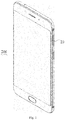
Fig. 1 illustrates a perspective view of a terminal according to an embodiment of the present disclosure. -
Fig. 2 illustrates a perspective view of an inserting device according to an embodiment of the present disclosure. -
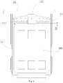
Fig. 3 illustrates a plan view of a card holder in a state where a data card is not installed according to an embodiment of the present disclosure. -
Fig. 4 illustrates a plan view of a card holder in a state where a data card is installed according to an embodiment of the present disclosure. -
Fig. 5 illustrates a perspective exploded view of a card holder according to an embodiment of the present disclosure. -
Fig. 6 illustrates a perspective exploded view of a card holder according to an embodiment of the present disclosure. -
Inserting device 100,card socket 10,accommodating space 12,card holder 20,card tray 21,card slot 211,upper card slot 2111,lower card slot 2112,sliding groove 212,first side wall 213,second side wall 214,third side wall 215,end portion 2152,middle portion 2154,fourth side wall 216,upper surface 217,lower surface 218,fixing groove 219,first wall 2191,second wall 2192,partition plate 21a, slidingblock 22, abuttingsurface 222,elastic element 23,handle 24,terminal 200,metal contact 30,data card 300. - Embodiments of the present disclosure will be further described with reference to accompanying drawings. The same or similar elements and the elements having same or similar functions are denoted by like reference numerals throughout the description.
- In addition, the embodiments described herein with reference to the drawings are explanatory, which aim to illustrate the embodiments of the present disclosure, but shall not be construed to limit the present disclosure.
- In the present disclosure, unless specified or limited otherwise, a structure in which a first feature is "on" or "below" a second feature may include an embodiment in which the first feature is in direct contact with the second feature, and may also include an embodiment in which the first feature and the second feature are not in direct contact with each other, but are contacted via an additional feature formed therebetween. Furthermore, a first feature "on," "above," or "on top of' a second feature may include an embodiment in which the first feature is right or obliquely "on," "above," or "on top of' the second feature, or just means that the first feature is at a height higher than that of the second feature; while a first feature "below," "under," or "on bottom of' a second feature may include an embodiment in which the first feature is right or obliquely "below," "under," or "on bottom of' the second feature, or just means that the first feature is at a height lower than that of the second feature.
- Reference throughout this specification to "some embodiments," "one embodiment," "some embodiments," "an example," "a specific example" or "some examples" means that a particular feature, structure, material, or characteristic described in connection with the embodiment or example is included in at least one embodiment or example of the present disclosure. Thus, the appearances of the above phrases in various places throughout this specification are not necessarily referring to the same embodiment or example of the present disclosure. Furthermore, the particular features, structures, materials, or characteristics may be combined in any suitable manner in one or more embodiments or examples. Moreover, those skilled in the art can combine different embodiments or examples described in this specification as well as features of different embodiments or examples on the premise of no mutual contradictions.
- Referring to
Figs. 1 to 4 , acard holder 20 according to embodiments of the present disclosure is configured to install adata card 300, and includes acard tray 21, asliding block 22 and anelastic element 23. Thedata card 300 can be a SIM card, a TF card, a SD card or the like. Aninserting device 100 according to embodiments of the present disclosure includes thecard holder 20 and acard socket 10, thecard socket 10 defines anaccommodating space 12, and thecard holder 20 can be movably inserted into or drawn out of theaccommodating space 12. Specifically, thecard holder 20 can be completely or partially drawn out of thecard socket 10, and after thedata card 300 is installed in thecard holder 20, thecard holder 20 is then pushed into thecard socket 10. Further, thecard socket 10 also includes a contact terminal (not illustrated), and when thedata card 300 is installed in thecard holder 20 and pushed into theaccommodating space 12, the contact terminal makes contact with ametal contact 30 of thedata card 300 so that the contact terminal can read data from or write data into thedata card 300. - A
terminal 200 according to embodiments of the present disclosure includes thecard holder 20. Further, theterminal 200 also includes thecard socket 10. Theterminal 200 may be various devices that can acquire data from thedata card 300 and process the data, or that can import data into thedata card 300, and for example, theterminal 200 can be a mobile phone, a tablet computer, a computing device, an information display device, or the like. - Referring to
Fig. 5 andFig. 6 together, thecard tray 21 defines acard slot 211 and asliding groove 212. Thecard slot 211 is configured to receive thedata card 300, and thecard slot 211 is in communication with thesliding groove 212. Specifically, thecard tray 21 exhibits a rectangular parallelepiped shape overall, and thecard slot 211 is defined by four side walls coupled end to end, the side walls including afirst side wall 213, asecond side wall 214, athird side wall 215 and afourth side wall 216. When thecard holder 20 needs to be pushed into thecard socket 10, thethird side wall 215 is first inserted into theaccommodating space 12, and then thecard holder 20 is pushed into thecard socket 10 along a first direction. Thefirst side wall 213 and thethird side wall 215 are opposite and extend along a second direction; thesecond side wall 214 and thefourth side wall 216 are opposite and extend along the first direction; thethird side wall 215 is the side wall inserted deepest when thecard holder 20 is inserted into theaccommodating space 12, while thefirst side wall 213 is the side wall inserted most shallowly when thecard holder 20 is inserted into theaccommodating space 12; thesecond side wall 214 couples a first end of thefirst side wall 213 and a first end of thethird side wall 215, while thefourth side wall 216 couples a second end of thefirst side wall 213 and a second end of thethird side wall 215. The first direction refers to a direction in which thecard holder 20 is inserted into thecard socket 10, the second direction is intersected with the first direction, and specifically the second direction is perpendicular to the first direction. - Respective thicknesses of the
first side wall 213, thesecond side wall 214 and thefourth side wall 216 can be equal, so as to allow thecard holder 20 to be inserted into thecard socket 10 easily. Thethird side wall 215 includes twoend portions 2152 coupled to thesecond side wall 214 and thefourth side wall 216 correspondingly, and amiddle portion 2154 coupling the twoend portions 2152. A height of eachend portion 2152 is equal to a height of thesecond side wall 214 and a height of thefourth side wall 216 correspondingly, so as to make it convenient for the twoend portions 2152 to abut against thedata card 300 to assist in fixing thedata card 300. A height of themiddle portion 2154 is lower than the height of eachend portion 2152, such that the contact terminal can conveniently extend into thecard slot 211 from themiddle portion 2154 and make contact with themetal contact 30. Further, a side of themiddle portion 2154 away from thecard slot 211 defines a chamfer, so as to facilitate insertion of the contact terminal from themiddle portion 2154 into thecard slot 211. - Referring to
Fig. 3 andFig. 4 together, thesliding block 22 is able to slide along thesliding groove 212 and abut against thedata card 300 when thedata card 300 is received in thecard slot 211. Specifically, thesliding groove 212 extends along the first direction, and thesliding block 22 can slide in thesliding groove 212 along the first direction. The slidingblock 22 includes anabutting surface 222, and abuts against thedata card 300 by means of theabutting surface 222. When thedata card 300 is not received in thecard slot 211, the slidingblock 22 is inserted into thecard slot 211 by a first depth D1 along the first direction; when thedata card 300 is received in thecard slot 211, the slidingblock 22 is inserted into thecard slot 211 by a second depth D2 along the first direction, and the first depth D1 is greater than the second depth D2. Certainly, the second depth D2 may vary asdifferent data cards 300 have different sizes. Further, the abuttingsurface 222 defines a limiting groove (not illustrated) in a position corresponding to thedata card 300, and when thedata card 300 is to be installed, a first side of thedata card 300 is aligned with the limiting groove and thedata card 300 is installed in thecard slot 211, such that the limiting groove further limits the position of thedata card 300, thereby avoiding slippage of thedata card 300 on theabutting surface 222. - The
elastic element 23 is coupled to the slidingblock 22, and configured to press the slidingblock 22 in a deformation state so that the slidingblock 22 abuts against thedata card 300. Specifically, theelastic element 23 and the slidingblock 22 can be integrally formed or separately formed, respective materials of theelastic element 23 and the slidingblock 22 can be consistent or inconsistent, and theelastic element 23 can be fixedly or movably coupled to the slidingblock 22. It could be understood that theelastic element 23 can be transformed between a natural state and a deformation state, and when thecard slot 211 hasn't received thedata card 300, theelastic element 23 is in the natural state and does not press the slidingblock 22, and thus the slidingblock 22 is inserted into thecard slot 211 by the first depth D1 along the first direction. When thedata card 300 needs to be installed in thecard slot 211, the first side of thedata card 300 abuts against the abuttingsurface 222 and urges the slidingblock 22 to slide in the slidinggroove 212 to reach the second depth D2 by which the slidingblock 22 is inserted into thecard slot 211 along the first direction, and a second side of thedata card 300 abuts against the twoend portions 2152 of thethird side wall 215, such that thedata card 300 is received in thecard slot 211, theelastic element 23 is in the deformation state and presses the slidingblock 22 along the first direction, and thedata card 300 is firmly installed in thecard slot 211 under the abutting action of the slidingblock 22 and theend portions 2152. - In the
card holder 20, the insertingdevice 100 and the terminal 200 mentioned above, theelastic element 23 can press the slidingblock 22 in the deformation state, such that the slidingblock 22 can abut against thedata card 300 when thedata card 300 is received in thecard slot 211, and hence thedata card 300 can be firmly installed on thecard holder 20 and will not be detached from thecard holder 20 when thecard holder 20 is flipped over. - The
card tray 21 further includes an upper surface 217 (as an example of the first surface) and a lower surface 218 (as an example of the second surface), and thelower surface 218 is opposite theupper surface 217. Specifically, theupper surface 217 can be parallel to thelower surface 218 to push thecard holder 20 into thecard socket 10 easily. When thecard holder 20 needs to be installed in thecard socket 10, thecard holder 20 is usually rotated to a state where theupper surface 217 faces upwards and thelower surface 218 faces downwards, and then thecard holder 20 is further pushed into thecard socket 10. - In some embodiments, one
card slot 211 is provided. Thecard slot 211 and the slidinggroove 212 are each defined in theupper surface 217, and neither thecard slot 211 nor the slidinggroove 212 passes through thelower surface 218, such that thedata card 300 will not fall off when theupper surface 217 faces upwards, and meanwhile thedata card 300 can be installed in thecard slot 211 easily, the state of the slidingblock 22 can be observed easily, and the slidingblock 22 can be assembled and disassembled easily. - In some embodiments, two
card slots 211 are provided and include an upper card slot 2111 (as an example of the first card slot) and a lower card slot 2112 (as an example of the second card slot), and theupper card slot 2111 is defined in theupper surface 217 while thelower card slot 2112 is defined in thelower surface 218. The slidinggroove 212 is defined in theupper surface 217, the slidinggroove 212 passes through theupper card slot 2111 and partially penetrates into thelower card slot 2112 in a depth direction, and the slidingblock 22 can abut against thedata card 300 when thedata card 300 is received in theupper card slot 2111 or when thedata card 300 is received in thesecond card slot 2112, or when thedate card 300 is received in each of thefirst card slot 2111 and thesecond card slot 2112. As a result, thecard holder 20 can receive twodata cards 300 at the same time, which expands the function of the terminal 200 and makes the structure of thecard holder 20 compact. Specifically, depending on specific use requirements, thedata card 300 can be installed in each of theupper card slot 2111 and thelower card slot 2112, or thedata card 300 can be installed in theupper card slot 2111 instead of thelower card slot 2112, or thedata card 300 can be installed in thelower card slot 2112 instead of theupper card slot 2111. The position of theupper card slot 2111 can be corresponding to that of thelower card slot 2112, and an opening depth of theupper card slot 2111 and that of thelower card slot 2112 can be the same or can be different. The slidinggroove 212 passes through theupper card slot 2111 and partially penetrates into thelower card slot 2112 in the depth direction, that is, the slidinggroove 212 runs through theupper surface 217 and a bottom of theupper card slot 2111, and partially penetrates into thelower card slot 2112, and the slidinggroove 212 is spaced apart from thelower surface 218. - Accordingly, in some embodiments, the
card tray 21 further includes apartition plate 21a, and thepartition plate 21a is disposed between theupper card slot 2111 and thelower card slot 2112 and configured to separate thedata card 300 received in theupper card slot 2111 from thedata card 300 received in thelower card slot 2112. Thus, thepartition plate 21a can separate twodata cards 300, such that when onedata card 300 is installed or uninstalled, theother data card 300 will not be affected. Additionally, thepartition plate 21a can hold thedata card 300 and prevent thedata card 300 from falling off in a direction perpendicular to theupper surface 217 and thelower surface 218. Specifically, twopartition plates 21a are provided and extend into thecard slot 211 correspondingly from thesecond side wall 214 and thefourth side wall 216. - In some embodiments, the
card tray 21 further includes a fixinggroove 219, the fixinggroove 219 is defined in theupper surface 217 and communicated with the slidinggroove 212, and theelastic element 23 is received in the fixinggroove 219. The fixinggroove 219 includes afirst wall 2191 adjacent to thecard slot 211 and asecond wall 2192 opposite thefirst wall 2191, and thesecond wall 2192 gradually extends away from thecard slot 211 along a direction from two ends of the fixinggroove 219 to a middle position of the fixinggroove 219. - Therefore, the state of the
elastic element 23 can be easily observed, and theelastic element 23 can be assembled or disassembled easily. Meanwhile, thesecond wall 2192 gradually extends away from thecard slot 211 along the direction from two ends of the fixinggroove 219 to the middle position of the fixinggroove 219, that is, a width of the fixinggroove 219 is gradually increased in the direction from two ends of the fixinggroove 219 to the middle position of the fixinggroove 219. As a result, when theelastic element 23 is deformed, friction between theelastic element 23 and thesecond wall 2192 is reduced, thereby prolonging the service life of theelastic element 23. Specifically, the fixinggroove 219 extends along the second direction overall, and thefirst wall 2191 extends along the second direction. In one embodiment, two ends of theelastic element 23 are fixed at two ends of the fixinggroove 219, specifically by means of gluing. In another embodiment, theelastic element 23 can abut against an inner wall of the fixinggroove 219, and when theelastic element 23 is deformed, theelastic element 23 abuts against the inner wall of the fixinggroove 219 and is fixed in the fixinggroove 219 by means of a frictional force provided by the fixinggroove 219. - In some embodiments, the sliding
block 22 slides in the slidinggroove 212 along a direction perpendicular to a length direction of theelastic element 23, and theelastic element 23 penetrates the slidingblock 22 or theelastic element 23 extends outwardly from two sides of the slidingblock 22. Thus, theelastic element 23 exerts a relatively large pressing action on the slidingblock 22 when deformed. Specifically, when theelastic element 23 penetrates the slidingblock 22, theelastic element 23 is in interference fit with the slidingblock 22, such that theelastic element 23 and the slidingblock 22 can be fitted tightly. Theelastic element 23 can have a columnar or spiral shape. - In some embodiments, the sliding
block 22 is located in a middle position in the length direction of theelastic element 23, and a sliding direction of the slidingblock 22 within the slidinggroove 212 is aligned with a middle position of thecard slot 211. Thus, the two sides of the slidingblock 22 are under relatively balanced pressing forces from theelastic element 23, thereby preventing the slidingblock 22 from coming out of the slidinggroove 212 due to unbalanced stress; the sliding direction of the slidingblock 22 is aligned with the middle position of thecard slot 211, thereby preventing thedata card 300 from coming out of thecard slot 211 when abutted by the slidingblock 22. - In some embodiments, the
card holder 20 further includes ahandle 24, thehandle 24 is coupled to an end of thecard tray 21, and the slidinggroove 212 is located between thecard slot 211 and thehandle 24. Specifically, thehandle 24 is coupled to thefirst side wall 213 of thecard slot 211, and thehandle 24 is substantially perpendicular to thecard tray 21, such that the user pushes thecard tray 21 into theaccommodating space 12 by pushing thehandle 24, and meanwhile thehandle 24 can be stuck outside thecard socket 10 to prevent thewhole card holder 20 from being inserted into theaccommodating space 12, which otherwise will make it difficult for thecard holder 20 to be taken out of theaccommodating space 12. - Reference throughout this specification to "certain embodiments," "one embodiment," "some embodiments," "an example," "a specific example" or "some examples" means that a particular feature, structure, material, or characteristic described in connection with the embodiment or example is included in at least one embodiment or example of the present disclosure. Thus, the appearances of the above phrases in various places throughout this specification are not necessarily referring to the same embodiment or example of the present disclosure. Furthermore, the particular features, structures, materials, or characteristics may be combined in any suitable manner in one or more embodiments or examples.
- In addition, terms such as "first" and "second" are used herein for purposes of description and are not intended to indicate or imply relative importance or significance or to imply the number of indicated technical features. Thus, the feature defined with "first" and "second" may comprise one or more of this feature. In the description of the present invention, "a plurality of' means two or more than two, unless specified otherwise.
- Although embodiments of the present disclosure have been illustrated and described, it would be appreciated by those skilled in the art that the embodiments are explanatory and cannot be construed to limit the present disclosure, and changes, modifications, alternatives and variations can be made in the embodiments without departing from the scope of the present disclosure. The scope of the present disclosure is defined by the claims and the like.
Claims (15)
- A card holder (20), configured to install a data card (300), comprising:a card tray (21) defining a card slot (211) and a sliding groove (212) in communication with the card slot (211), the card slot (211) being configured to receive the data card (300);a sliding block (22) capable of sliding along the sliding groove (212); andan elastic element (23) coupled to the sliding block (22), fixed to the card tray (21), and configured to press the sliding block (22) to make the sliding block (22) capable of abutting against the data card (300) when the elastic element (23) is in a deformation state.
- The card holder (20) according to claim 1, wherein the card tray (21) further comprises a first surface (217) and a second surface (218) opposite the first surface (217), the card slot (211) is defined in the first surface (217) and the sliding groove (212) is defined in the first surface (217).
- The card holder (20) according to claim 1, wherein the card tray (21) further comprises a first surface (217) and a second surface (218) opposite the first surface (217); the card slot (211) comprises a first card slot (2111) defined in the first surface (217) and a second card slot (2112) defined in the second surface (218); the sliding groove (212) is defined in the first surface (217), and passes through the first card slot (2111) and partially penetrates into the second card slot (2112) in a depth direction; the sliding block (22) is able to abut against the data card (300) when the data card (300) is received in the first card slot (2111), or when the data card (300) is received in the second card slot (2112), or when the date card (300) is received in each of the first card slot (2111) and the second card slot (2112).
- The card holder (20) according to claim 3, wherein the card tray (21) further comprises a partition plate (21a) provided between the first card slot (2111) and the second card slot (2112), and the partition plate (21a) is configured to separate the data card (300) received in the first card slot (2111) from the data card (300) received in the second card slot (2112).
- The card holder (20) according to any one of claims 2 to 4, wherein the card tray (21) further comprises a fixing groove (219) defined in the first surface (217), the fixing groove (219) is in communication with the sliding groove (212), and the elastic element (23) is received in the fixing groove (219); the fixing groove (219) comprises a first wall (2191) adjacent to the card slot (211) and a second wall (2192) opposite the first wall (2191), and the second wall (2192) gradually extends away from the card slot (211) along a direction from two ends of the fixing groove (219) to a middle position of the fixing groove (219).
- The card holder (20) according to claim 5, wherein two ends of the elastic element (23) are fixed at the two ends of the fixing groove (219).
- The card holder (20) according to claim 5, wherein the elastic element (23) is able to abut against an inner wall of the fixing groove (219).
- The card holder (20) according to any one of claims 1 to 7, wherein the sliding block (22) slides in the sliding groove (212) along a direction perpendicular to a length direction of the elastic element (23), and the elastic element (23) penetrates the sliding block (22) or extends outwardly from two sides of the sliding block (22).
- The card holder (20) according to claim 8, wherein the sliding block (22) is located in a middle position in the length direction of the elastic element (23), and a sliding direction of the sliding block (22) within the sliding groove (212) is aligned with a middle position of the card slot (211).
- The card holder (20) according to any one of claims 1 to 9, further comprising a handle (24) coupled to an end of the card tray (21), the sliding groove (212) being located between the card slot (211) and the handle (24).
- The card holder (20) according to any one of claims 1 to 10, wherein the card tray (21) exhibits a rectangular parallelepiped shape overall, and the card slot (211) is defined by four side walls coupled end to end, the side walls comprising a first side wall (213), a second side wall (214), a third side wall (215) and a fourth side wall (216).
- The card holder (20) according to claim 11, wherein the first side wall (213) and the third side wall (215) are opposite and extend along a second direction; the second side wall (214) and the fourth side wall (216) are opposite and extend along a first direction; the second side wall (214) couples a first end of the first side wall (213) and a first end of the third side wall (215), while the fourth side wall (216) couples a second end of the first side wall (213) and a second end of the third side wall (215).
- The card holder (20) according to claim 11 or 12, wherein when the data card (300) is not received in the card slot (211), the sliding block (22) is inserted into the card slot (211) by a first depth (D1) along the first direction; when the data card (300) is received in the card slot (211), the sliding block (22) is inserted into the card slot (211) by a second depth (D2) along the first direction, and the first depth (D1) is greater than the second depth (D2).
- An inserting device (100), comprising:a card socket (10) defining an accommodating space (12); anda card holder (20) according to any one of claims 1 to 13, capable of being movably inserted into or drawn out of the accommodating space (12).
- A terminal (200), comprising a card holder (20) according to any one of claims 1 to 13.
Applications Claiming Priority (2)
| Application Number | Priority Date | Filing Date | Title |
|---|---|---|---|
| CN201720416076.1U CN206743227U (en) | 2017-04-19 | 2017-04-19 | Trays, Sockets and Terminations |
| CN201710258883.XA CN106953653B (en) | 2017-04-19 | 2017-04-19 | Card holder, plug-in device and terminal |
Publications (2)
| Publication Number | Publication Date |
|---|---|
| EP3393048A1 true EP3393048A1 (en) | 2018-10-24 |
| EP3393048B1 EP3393048B1 (en) | 2019-05-15 |
Family
ID=60972006
Family Applications (1)
| Application Number | Title | Priority Date | Filing Date |
|---|---|---|---|
| EP18150569.4A Active EP3393048B1 (en) | 2017-04-19 | 2018-01-08 | Card holder, inserting device and terminal |
Country Status (8)
| Country | Link |
|---|---|
| US (1) | US10483691B2 (en) |
| EP (1) | EP3393048B1 (en) |
| JP (1) | JP6999678B2 (en) |
| AU (1) | AU2018253657B9 (en) |
| ES (1) | ES2730812T3 (en) |
| SG (1) | SG11201906144UA (en) |
| TW (1) | TWI635659B (en) |
| WO (1) | WO2018192275A1 (en) |
Cited By (2)
| Publication number | Priority date | Publication date | Assignee | Title |
|---|---|---|---|---|
| CN115207698A (en) * | 2022-07-20 | 2022-10-18 | 维沃移动通信有限公司 | Electronic device |
| CN116193785A (en) * | 2023-03-23 | 2023-05-30 | 维沃移动通信有限公司 | Card receiving device and electronic equipment |
Families Citing this family (3)
| Publication number | Priority date | Publication date | Assignee | Title |
|---|---|---|---|---|
| JP7025994B2 (en) * | 2018-05-22 | 2022-02-25 | 日本航空電子工業株式会社 | tray |
| CN112821911B (en) * | 2020-12-30 | 2023-04-07 | 维沃移动通信有限公司 | Card holder module and electronic equipment |
| JP2025112060A (en) * | 2024-01-18 | 2025-07-31 | Necパーソナルコンピュータ株式会社 | Card tray and electronic device |
Citations (3)
| Publication number | Priority date | Publication date | Assignee | Title |
|---|---|---|---|---|
| JP2013222653A (en) * | 2012-04-18 | 2013-10-28 | Smk Corp | Card connector |
| US20140016275A1 (en) * | 2011-12-27 | 2014-01-16 | Molex Incorporated | Card Tray And Tray Connector |
| EP2821939A1 (en) * | 2013-07-02 | 2015-01-07 | Japan Aviation Electronics Industry Limited | SIM card connector |
Family Cites Families (14)
| Publication number | Priority date | Publication date | Assignee | Title |
|---|---|---|---|---|
| US8237252B2 (en) * | 2009-07-22 | 2012-08-07 | Stats Chippac, Ltd. | Semiconductor device and method of embedding thermally conductive layer in interconnect structure for heat dissipation |
| US8597058B2 (en) | 2012-03-22 | 2013-12-03 | Proconn Technology Co., Ltd. | Card holder |
| TWI511382B (en) * | 2012-08-21 | 2015-12-01 | Chiun Mai Comm Systems Inc | Chip card holder and electronic device using the same |
| TWM469642U (en) * | 2013-03-28 | 2014-01-01 | Molex Inc | Electrical card connector |
| CN104241925A (en) * | 2013-06-11 | 2014-12-24 | 深圳富泰宏精密工业有限公司 | Chip card installing and taking structure |
| CN104300305B (en) | 2013-07-18 | 2018-08-28 | 美国莫列斯股份有限公司 | Electronic card tray, electronic card connecting device and electronic device |
| CN203617483U (en) * | 2013-11-27 | 2014-05-28 | 昆山龙梦电子科技有限公司 | PIN bracket for preventing damages |
| TWM483573U (en) * | 2014-01-28 | 2014-08-01 | Molex Inc | Electronic card connector |
| JP2016062854A (en) * | 2014-09-22 | 2016-04-25 | Smk株式会社 | Card connector |
| CN204720601U (en) | 2015-05-13 | 2015-10-21 | 中兴通讯股份有限公司 | Location Kato and mobile communication terminal |
| CN106450881B (en) | 2016-09-27 | 2019-10-29 | 北京小米移动软件有限公司 | A kind of Kato |
| CN206148756U (en) | 2016-09-27 | 2017-05-03 | 北京小米移动软件有限公司 | a Cato |
| CN106953653B (en) | 2017-04-19 | 2022-07-12 | Oppo广东移动通信有限公司 | Card holder, plug-in device and terminal |
| CN206743227U (en) | 2017-04-19 | 2017-12-12 | 广东欧珀移动通信有限公司 | Trays, Sockets and Terminations |
-
2017
- 2017-12-13 TW TW106143761A patent/TWI635659B/en active
- 2017-12-22 US US15/852,286 patent/US10483691B2/en active Active
-
2018
- 2018-01-04 SG SG11201906144UA patent/SG11201906144UA/en unknown
- 2018-01-04 AU AU2018253657A patent/AU2018253657B9/en not_active Ceased
- 2018-01-04 JP JP2019537209A patent/JP6999678B2/en not_active Expired - Fee Related
- 2018-01-04 WO PCT/CN2018/071378 patent/WO2018192275A1/en not_active Ceased
- 2018-01-08 ES ES18150569T patent/ES2730812T3/en active Active
- 2018-01-08 EP EP18150569.4A patent/EP3393048B1/en active Active
Patent Citations (3)
| Publication number | Priority date | Publication date | Assignee | Title |
|---|---|---|---|---|
| US20140016275A1 (en) * | 2011-12-27 | 2014-01-16 | Molex Incorporated | Card Tray And Tray Connector |
| JP2013222653A (en) * | 2012-04-18 | 2013-10-28 | Smk Corp | Card connector |
| EP2821939A1 (en) * | 2013-07-02 | 2015-01-07 | Japan Aviation Electronics Industry Limited | SIM card connector |
Cited By (2)
| Publication number | Priority date | Publication date | Assignee | Title |
|---|---|---|---|---|
| CN115207698A (en) * | 2022-07-20 | 2022-10-18 | 维沃移动通信有限公司 | Electronic device |
| CN116193785A (en) * | 2023-03-23 | 2023-05-30 | 维沃移动通信有限公司 | Card receiving device and electronic equipment |
Also Published As
| Publication number | Publication date |
|---|---|
| TW201840063A (en) | 2018-11-01 |
| JP2020505682A (en) | 2020-02-20 |
| AU2018253657B2 (en) | 2020-05-21 |
| JP6999678B2 (en) | 2022-01-18 |
| US20180309234A1 (en) | 2018-10-25 |
| AU2018253657A1 (en) | 2019-07-25 |
| SG11201906144UA (en) | 2019-08-27 |
| TWI635659B (en) | 2018-09-11 |
| WO2018192275A1 (en) | 2018-10-25 |
| US10483691B2 (en) | 2019-11-19 |
| ES2730812T3 (en) | 2019-11-12 |
| AU2018253657B9 (en) | 2020-06-18 |
| EP3393048B1 (en) | 2019-05-15 |
Similar Documents
| Publication | Publication Date | Title |
|---|---|---|
| EP3393048A1 (en) | Card holder, inserting device and terminal | |
| CN106953653B (en) | Card holder, plug-in device and terminal | |
| US8614897B2 (en) | Chip card holding mechanism and portable electronic device using the same | |
| US8226179B2 (en) | Housing with hook configuration | |
| US20110267787A1 (en) | Chip card holder for portable electronic device | |
| CN102208722B (en) | Electronic device capable of replacing electronic card | |
| JP5527558B2 (en) | Card connector | |
| EP2757702A1 (en) | Sim card socket and terminal device including the same | |
| US7473122B2 (en) | Electrical connector having an improved protecting mechanism | |
| CN108551013B (en) | Deck component and electronic equipment | |
| CN105449437B (en) | Plug-in device and terminal | |
| CN101931671A (en) | Electronic equipment | |
| TW201524315A (en) | Securing device for data-storage device | |
| US20120244741A1 (en) | Connector | |
| US8434206B2 (en) | Clutching jig | |
| CN109309298B (en) | Stack type two-in-one card holder and electronic equipment | |
| CN206743227U (en) | Trays, Sockets and Terminations | |
| US7618273B1 (en) | Memory card connector | |
| US8783797B2 (en) | Electronic device having card holder | |
| CN102694319A (en) | Connector and electronic device | |
| CN205264914U (en) | Plug -in card device and terminal | |
| US20080254658A1 (en) | Memory card connector | |
| CN222896842U (en) | Card Connectors | |
| HK1236289B (en) | Card holder, docking device and terminal | |
| HK1236289A1 (en) | Card holder, docking device and terminal |
Legal Events
| Date | Code | Title | Description |
|---|---|---|---|
| PUAI | Public reference made under article 153(3) epc to a published international application that has entered the european phase |
Free format text: ORIGINAL CODE: 0009012 |
|
| STAA | Information on the status of an ep patent application or granted ep patent |
Free format text: STATUS: REQUEST FOR EXAMINATION WAS MADE |
|
| 17P | Request for examination filed |
Effective date: 20180810 |
|
| AK | Designated contracting states |
Kind code of ref document: A1 Designated state(s): AL AT BE BG CH CY CZ DE DK EE ES FI FR GB GR HR HU IE IS IT LI LT LU LV MC MK MT NL NO PL PT RO RS SE SI SK SM TR |
|
| AX | Request for extension of the european patent |
Extension state: BA ME |
|
| GRAP | Despatch of communication of intention to grant a patent |
Free format text: ORIGINAL CODE: EPIDOSNIGR1 |
|
| STAA | Information on the status of an ep patent application or granted ep patent |
Free format text: STATUS: GRANT OF PATENT IS INTENDED |
|
| INTG | Intention to grant announced |
Effective date: 20181211 |
|
| GRAS | Grant fee paid |
Free format text: ORIGINAL CODE: EPIDOSNIGR3 |
|
| GRAA | (expected) grant |
Free format text: ORIGINAL CODE: 0009210 |
|
| STAA | Information on the status of an ep patent application or granted ep patent |
Free format text: STATUS: THE PATENT HAS BEEN GRANTED |
|
| AK | Designated contracting states |
Kind code of ref document: B1 Designated state(s): AL AT BE BG CH CY CZ DE DK EE ES FI FR GB GR HR HU IE IS IT LI LT LU LV MC MK MT NL NO PL PT RO RS SE SI SK SM TR |
|
| REG | Reference to a national code |
Ref country code: CH Ref legal event code: EP |
|
| REG | Reference to a national code |
Ref country code: DE Ref legal event code: R096 Ref document number: 602018000059 Country of ref document: DE |
|
| REG | Reference to a national code |
Ref country code: IE Ref legal event code: FG4D |
|
| REG | Reference to a national code |
Ref country code: NL Ref legal event code: FP |
|
| REG | Reference to a national code |
Ref country code: LT Ref legal event code: MG4D |
|
| PG25 | Lapsed in a contracting state [announced via postgrant information from national office to epo] |
Ref country code: AL Free format text: LAPSE BECAUSE OF FAILURE TO SUBMIT A TRANSLATION OF THE DESCRIPTION OR TO PAY THE FEE WITHIN THE PRESCRIBED TIME-LIMIT Effective date: 20190515 Ref country code: NO Free format text: LAPSE BECAUSE OF FAILURE TO SUBMIT A TRANSLATION OF THE DESCRIPTION OR TO PAY THE FEE WITHIN THE PRESCRIBED TIME-LIMIT Effective date: 20190815 Ref country code: PT Free format text: LAPSE BECAUSE OF FAILURE TO SUBMIT A TRANSLATION OF THE DESCRIPTION OR TO PAY THE FEE WITHIN THE PRESCRIBED TIME-LIMIT Effective date: 20190915 Ref country code: SE Free format text: LAPSE BECAUSE OF FAILURE TO SUBMIT A TRANSLATION OF THE DESCRIPTION OR TO PAY THE FEE WITHIN THE PRESCRIBED TIME-LIMIT Effective date: 20190515 Ref country code: FI Free format text: LAPSE BECAUSE OF FAILURE TO SUBMIT A TRANSLATION OF THE DESCRIPTION OR TO PAY THE FEE WITHIN THE PRESCRIBED TIME-LIMIT Effective date: 20190515 Ref country code: LT Free format text: LAPSE BECAUSE OF FAILURE TO SUBMIT A TRANSLATION OF THE DESCRIPTION OR TO PAY THE FEE WITHIN THE PRESCRIBED TIME-LIMIT Effective date: 20190515 Ref country code: HR Free format text: LAPSE BECAUSE OF FAILURE TO SUBMIT A TRANSLATION OF THE DESCRIPTION OR TO PAY THE FEE WITHIN THE PRESCRIBED TIME-LIMIT Effective date: 20190515 |
|
| REG | Reference to a national code |
Ref country code: ES Ref legal event code: FG2A Ref document number: 2730812 Country of ref document: ES Kind code of ref document: T3 Effective date: 20191112 |
|
| PG25 | Lapsed in a contracting state [announced via postgrant information from national office to epo] |
Ref country code: RS Free format text: LAPSE BECAUSE OF FAILURE TO SUBMIT A TRANSLATION OF THE DESCRIPTION OR TO PAY THE FEE WITHIN THE PRESCRIBED TIME-LIMIT Effective date: 20190515 Ref country code: LV Free format text: LAPSE BECAUSE OF FAILURE TO SUBMIT A TRANSLATION OF THE DESCRIPTION OR TO PAY THE FEE WITHIN THE PRESCRIBED TIME-LIMIT Effective date: 20190515 Ref country code: BG Free format text: LAPSE BECAUSE OF FAILURE TO SUBMIT A TRANSLATION OF THE DESCRIPTION OR TO PAY THE FEE WITHIN THE PRESCRIBED TIME-LIMIT Effective date: 20190815 Ref country code: GR Free format text: LAPSE BECAUSE OF FAILURE TO SUBMIT A TRANSLATION OF THE DESCRIPTION OR TO PAY THE FEE WITHIN THE PRESCRIBED TIME-LIMIT Effective date: 20190816 |
|
| RAP2 | Party data changed (patent owner data changed or rights of a patent transferred) |
Owner name: GUANGDONG OPPO MOBILE TELECOMMUNICATIONS CORP., LT |
|
| REG | Reference to a national code |
Ref country code: AT Ref legal event code: MK05 Ref document number: 1134630 Country of ref document: AT Kind code of ref document: T Effective date: 20190515 |
|
| PG25 | Lapsed in a contracting state [announced via postgrant information from national office to epo] |
Ref country code: EE Free format text: LAPSE BECAUSE OF FAILURE TO SUBMIT A TRANSLATION OF THE DESCRIPTION OR TO PAY THE FEE WITHIN THE PRESCRIBED TIME-LIMIT Effective date: 20190515 Ref country code: AT Free format text: LAPSE BECAUSE OF FAILURE TO SUBMIT A TRANSLATION OF THE DESCRIPTION OR TO PAY THE FEE WITHIN THE PRESCRIBED TIME-LIMIT Effective date: 20190515 Ref country code: DK Free format text: LAPSE BECAUSE OF FAILURE TO SUBMIT A TRANSLATION OF THE DESCRIPTION OR TO PAY THE FEE WITHIN THE PRESCRIBED TIME-LIMIT Effective date: 20190515 Ref country code: SK Free format text: LAPSE BECAUSE OF FAILURE TO SUBMIT A TRANSLATION OF THE DESCRIPTION OR TO PAY THE FEE WITHIN THE PRESCRIBED TIME-LIMIT Effective date: 20190515 Ref country code: CZ Free format text: LAPSE BECAUSE OF FAILURE TO SUBMIT A TRANSLATION OF THE DESCRIPTION OR TO PAY THE FEE WITHIN THE PRESCRIBED TIME-LIMIT Effective date: 20190515 |
|
| REG | Reference to a national code |
Ref country code: DE Ref legal event code: R097 Ref document number: 602018000059 Country of ref document: DE |
|
| PG25 | Lapsed in a contracting state [announced via postgrant information from national office to epo] |
Ref country code: SM Free format text: LAPSE BECAUSE OF FAILURE TO SUBMIT A TRANSLATION OF THE DESCRIPTION OR TO PAY THE FEE WITHIN THE PRESCRIBED TIME-LIMIT Effective date: 20190515 |
|
| PLBE | No opposition filed within time limit |
Free format text: ORIGINAL CODE: 0009261 |
|
| STAA | Information on the status of an ep patent application or granted ep patent |
Free format text: STATUS: NO OPPOSITION FILED WITHIN TIME LIMIT |
|
| PG25 | Lapsed in a contracting state [announced via postgrant information from national office to epo] |
Ref country code: TR Free format text: LAPSE BECAUSE OF FAILURE TO SUBMIT A TRANSLATION OF THE DESCRIPTION OR TO PAY THE FEE WITHIN THE PRESCRIBED TIME-LIMIT Effective date: 20190515 |
|
| 26N | No opposition filed |
Effective date: 20200218 |
|
| PG25 | Lapsed in a contracting state [announced via postgrant information from national office to epo] |
Ref country code: PL Free format text: LAPSE BECAUSE OF FAILURE TO SUBMIT A TRANSLATION OF THE DESCRIPTION OR TO PAY THE FEE WITHIN THE PRESCRIBED TIME-LIMIT Effective date: 20190515 |
|
| PG25 | Lapsed in a contracting state [announced via postgrant information from national office to epo] |
Ref country code: MC Free format text: LAPSE BECAUSE OF FAILURE TO SUBMIT A TRANSLATION OF THE DESCRIPTION OR TO PAY THE FEE WITHIN THE PRESCRIBED TIME-LIMIT Effective date: 20190515 |
|
| REG | Reference to a national code |
Ref country code: BE Ref legal event code: MM Effective date: 20200131 |
|
| PG25 | Lapsed in a contracting state [announced via postgrant information from national office to epo] |
Ref country code: LU Free format text: LAPSE BECAUSE OF NON-PAYMENT OF DUE FEES Effective date: 20200108 |
|
| PG25 | Lapsed in a contracting state [announced via postgrant information from national office to epo] |
Ref country code: BE Free format text: LAPSE BECAUSE OF NON-PAYMENT OF DUE FEES Effective date: 20200131 |
|
| PG25 | Lapsed in a contracting state [announced via postgrant information from national office to epo] |
Ref country code: IE Free format text: LAPSE BECAUSE OF NON-PAYMENT OF DUE FEES Effective date: 20200108 |
|
| REG | Reference to a national code |
Ref country code: CH Ref legal event code: PL |
|
| PG25 | Lapsed in a contracting state [announced via postgrant information from national office to epo] |
Ref country code: CH Free format text: LAPSE BECAUSE OF NON-PAYMENT OF DUE FEES Effective date: 20210131 Ref country code: LI Free format text: LAPSE BECAUSE OF NON-PAYMENT OF DUE FEES Effective date: 20210131 |
|
| PG25 | Lapsed in a contracting state [announced via postgrant information from national office to epo] |
Ref country code: MT Free format text: LAPSE BECAUSE OF FAILURE TO SUBMIT A TRANSLATION OF THE DESCRIPTION OR TO PAY THE FEE WITHIN THE PRESCRIBED TIME-LIMIT Effective date: 20190515 Ref country code: CY Free format text: LAPSE BECAUSE OF FAILURE TO SUBMIT A TRANSLATION OF THE DESCRIPTION OR TO PAY THE FEE WITHIN THE PRESCRIBED TIME-LIMIT Effective date: 20190515 |
|
| PG25 | Lapsed in a contracting state [announced via postgrant information from national office to epo] |
Ref country code: RO Free format text: LAPSE BECAUSE OF FAILURE TO SUBMIT A TRANSLATION OF THE DESCRIPTION OR TO PAY THE FEE WITHIN THE PRESCRIBED TIME-LIMIT Effective date: 20190515 Ref country code: MK Free format text: LAPSE BECAUSE OF FAILURE TO SUBMIT A TRANSLATION OF THE DESCRIPTION OR TO PAY THE FEE WITHIN THE PRESCRIBED TIME-LIMIT Effective date: 20190515 Ref country code: IS Free format text: LAPSE BECAUSE OF FAILURE TO SUBMIT A TRANSLATION OF THE DESCRIPTION OR TO PAY THE FEE WITHIN THE PRESCRIBED TIME-LIMIT Effective date: 20190915 |
|
| PGFP | Annual fee paid to national office [announced via postgrant information from national office to epo] |
Ref country code: NL Payment date: 20221222 Year of fee payment: 6 |
|
| PGFP | Annual fee paid to national office [announced via postgrant information from national office to epo] |
Ref country code: FR Payment date: 20230125 Year of fee payment: 6 Ref country code: ES Payment date: 20230206 Year of fee payment: 6 |
|
| PGFP | Annual fee paid to national office [announced via postgrant information from national office to epo] |
Ref country code: IT Payment date: 20230111 Year of fee payment: 6 Ref country code: GB Payment date: 20230123 Year of fee payment: 6 Ref country code: DE Payment date: 20230112 Year of fee payment: 6 |
|
| P01 | Opt-out of the competence of the unified patent court (upc) registered |
Effective date: 20230412 |
|
| PG25 | Lapsed in a contracting state [announced via postgrant information from national office to epo] |
Ref country code: SI Free format text: LAPSE BECAUSE OF FAILURE TO SUBMIT A TRANSLATION OF THE DESCRIPTION OR TO PAY THE FEE WITHIN THE PRESCRIBED TIME-LIMIT Effective date: 20190515 |
|
| REG | Reference to a national code |
Ref country code: DE Ref legal event code: R119 Ref document number: 602018000059 Country of ref document: DE |
|
| REG | Reference to a national code |
Ref country code: NL Ref legal event code: MM Effective date: 20240201 |
|
| GBPC | Gb: european patent ceased through non-payment of renewal fee |
Effective date: 20240108 |
|
| PG25 | Lapsed in a contracting state [announced via postgrant information from national office to epo] |
Ref country code: DE Free format text: LAPSE BECAUSE OF NON-PAYMENT OF DUE FEES Effective date: 20240801 |
|
| PG25 | Lapsed in a contracting state [announced via postgrant information from national office to epo] |
Ref country code: GB Free format text: LAPSE BECAUSE OF NON-PAYMENT OF DUE FEES Effective date: 20240108 |
|
| PG25 | Lapsed in a contracting state [announced via postgrant information from national office to epo] |
Ref country code: FR Free format text: LAPSE BECAUSE OF NON-PAYMENT OF DUE FEES Effective date: 20240131 |
|
| PG25 | Lapsed in a contracting state [announced via postgrant information from national office to epo] |
Ref country code: NL Free format text: LAPSE BECAUSE OF NON-PAYMENT OF DUE FEES Effective date: 20240201 |
|
| PG25 | Lapsed in a contracting state [announced via postgrant information from national office to epo] |
Ref country code: NL Free format text: LAPSE BECAUSE OF NON-PAYMENT OF DUE FEES Effective date: 20240201 Ref country code: GB Free format text: LAPSE BECAUSE OF NON-PAYMENT OF DUE FEES Effective date: 20240108 Ref country code: FR Free format text: LAPSE BECAUSE OF NON-PAYMENT OF DUE FEES Effective date: 20240131 Ref country code: DE Free format text: LAPSE BECAUSE OF NON-PAYMENT OF DUE FEES Effective date: 20240801 |
|
| PG25 | Lapsed in a contracting state [announced via postgrant information from national office to epo] |
Ref country code: IT Free format text: LAPSE BECAUSE OF NON-PAYMENT OF DUE FEES Effective date: 20240108 |
|
| REG | Reference to a national code |
Ref country code: ES Ref legal event code: FD2A Effective date: 20250226 |
|
| PG25 | Lapsed in a contracting state [announced via postgrant information from national office to epo] |
Ref country code: ES Free format text: LAPSE BECAUSE OF NON-PAYMENT OF DUE FEES Effective date: 20240109 |